US6166787A - Optical display device having prismatic film for enhanced viewing - Google Patents
Optical display device having prismatic film for enhanced viewing Download PDFInfo
- Publication number
- US6166787A US6166787A US09/040,047 US4004798A US6166787A US 6166787 A US6166787 A US 6166787A US 4004798 A US4004798 A US 4004798A US 6166787 A US6166787 A US 6166787A
- Authority
- US
- United States
- Prior art keywords
- cell
- prismatic
- optical
- display device
- optical display
- Prior art date
- Legal status (The legal status is an assumption and is not a legal conclusion. Google has not performed a legal analysis and makes no representation as to the accuracy of the status listed.)
- Expired - Lifetime
Links
Images


Classifications
-
- G—PHYSICS
- G02—OPTICS
- G02F—OPTICAL DEVICES OR ARRANGEMENTS FOR THE CONTROL OF LIGHT BY MODIFICATION OF THE OPTICAL PROPERTIES OF THE MEDIA OF THE ELEMENTS INVOLVED THEREIN; NON-LINEAR OPTICS; FREQUENCY-CHANGING OF LIGHT; OPTICAL LOGIC ELEMENTS; OPTICAL ANALOGUE/DIGITAL CONVERTERS
- G02F1/00—Devices or arrangements for the control of the intensity, colour, phase, polarisation or direction of light arriving from an independent light source, e.g. switching, gating or modulating; Non-linear optics
- G02F1/01—Devices or arrangements for the control of the intensity, colour, phase, polarisation or direction of light arriving from an independent light source, e.g. switching, gating or modulating; Non-linear optics for the control of the intensity, phase, polarisation or colour
- G02F1/13—Devices or arrangements for the control of the intensity, colour, phase, polarisation or direction of light arriving from an independent light source, e.g. switching, gating or modulating; Non-linear optics for the control of the intensity, phase, polarisation or colour based on liquid crystals, e.g. single liquid crystal display cells
- G02F1/133—Constructional arrangements; Operation of liquid crystal cells; Circuit arrangements
- G02F1/1333—Constructional arrangements; Manufacturing methods
- G02F1/1335—Structural association of cells with optical devices, e.g. polarisers or reflectors
- G02F1/133526—Lenses, e.g. microlenses or Fresnel lenses
-
- G—PHYSICS
- G02—OPTICS
- G02B—OPTICAL ELEMENTS, SYSTEMS OR APPARATUS
- G02B1/00—Optical elements characterised by the material of which they are made; Optical coatings for optical elements
- G02B1/10—Optical coatings produced by application to, or surface treatment of, optical elements
- G02B1/11—Anti-reflection coatings
-
- G—PHYSICS
- G02—OPTICS
- G02B—OPTICAL ELEMENTS, SYSTEMS OR APPARATUS
- G02B5/00—Optical elements other than lenses
- G02B5/04—Prisms
- G02B5/045—Prism arrays
-
- G—PHYSICS
- G02—OPTICS
- G02F—OPTICAL DEVICES OR ARRANGEMENTS FOR THE CONTROL OF LIGHT BY MODIFICATION OF THE OPTICAL PROPERTIES OF THE MEDIA OF THE ELEMENTS INVOLVED THEREIN; NON-LINEAR OPTICS; FREQUENCY-CHANGING OF LIGHT; OPTICAL LOGIC ELEMENTS; OPTICAL ANALOGUE/DIGITAL CONVERTERS
- G02F1/00—Devices or arrangements for the control of the intensity, colour, phase, polarisation or direction of light arriving from an independent light source, e.g. switching, gating or modulating; Non-linear optics
- G02F1/01—Devices or arrangements for the control of the intensity, colour, phase, polarisation or direction of light arriving from an independent light source, e.g. switching, gating or modulating; Non-linear optics for the control of the intensity, phase, polarisation or colour
- G02F1/13—Devices or arrangements for the control of the intensity, colour, phase, polarisation or direction of light arriving from an independent light source, e.g. switching, gating or modulating; Non-linear optics for the control of the intensity, phase, polarisation or colour based on liquid crystals, e.g. single liquid crystal display cells
- G02F1/133—Constructional arrangements; Operation of liquid crystal cells; Circuit arrangements
- G02F1/1333—Constructional arrangements; Manufacturing methods
- G02F1/1335—Structural association of cells with optical devices, e.g. polarisers or reflectors
- G02F1/133504—Diffusing, scattering, diffracting elements
-
- G—PHYSICS
- G02—OPTICS
- G02F—OPTICAL DEVICES OR ARRANGEMENTS FOR THE CONTROL OF LIGHT BY MODIFICATION OF THE OPTICAL PROPERTIES OF THE MEDIA OF THE ELEMENTS INVOLVED THEREIN; NON-LINEAR OPTICS; FREQUENCY-CHANGING OF LIGHT; OPTICAL LOGIC ELEMENTS; OPTICAL ANALOGUE/DIGITAL CONVERTERS
- G02F1/00—Devices or arrangements for the control of the intensity, colour, phase, polarisation or direction of light arriving from an independent light source, e.g. switching, gating or modulating; Non-linear optics
- G02F1/01—Devices or arrangements for the control of the intensity, colour, phase, polarisation or direction of light arriving from an independent light source, e.g. switching, gating or modulating; Non-linear optics for the control of the intensity, phase, polarisation or colour
- G02F1/13—Devices or arrangements for the control of the intensity, colour, phase, polarisation or direction of light arriving from an independent light source, e.g. switching, gating or modulating; Non-linear optics for the control of the intensity, phase, polarisation or colour based on liquid crystals, e.g. single liquid crystal display cells
- G02F1/133—Constructional arrangements; Operation of liquid crystal cells; Circuit arrangements
- G02F1/1333—Constructional arrangements; Manufacturing methods
- G02F1/1335—Structural association of cells with optical devices, e.g. polarisers or reflectors
- G02F1/133502—Antiglare, refractive index matching layers
-
- G—PHYSICS
- G02—OPTICS
- G02F—OPTICAL DEVICES OR ARRANGEMENTS FOR THE CONTROL OF LIGHT BY MODIFICATION OF THE OPTICAL PROPERTIES OF THE MEDIA OF THE ELEMENTS INVOLVED THEREIN; NON-LINEAR OPTICS; FREQUENCY-CHANGING OF LIGHT; OPTICAL LOGIC ELEMENTS; OPTICAL ANALOGUE/DIGITAL CONVERTERS
- G02F2203/00—Function characteristic
- G02F2203/22—Function characteristic diffractive
Definitions
- the present invention relates generally to an optical display device. More particularly, the present invention relates to a reflective, optical display device having a prismatic film to enhance a viewer's perceived brightness of the display in a preferred viewing cone.
- Prior-art optical displays include back-lighted liquid crystal displays and reflective liquid crystal displays.
- Back-lighted displays consume more power than reflective displays do.
- back-lighted displays are larger and heavier than reflective displays.
- back-lighted displays have significant disadvantages for use in portable electronic products.
- Reflective displays rely on ambient light to illuminate the pixels, symbols, or characters of the displays. Reflective displays are susceptible to the negative influence of glare that is typically attendant with the ambient light illuminating the display. As used herein, glare or glare light rays refer to an unwanted reflection of incident ambient light off any interface associated with the display device. The glare light rays produce a reflection which has no utility for viewing purposes. Conventional reflectors within displays frequently reflect light such that the direction of maximum brightness of the display is at substantially the same angle as the glare light rays. Consequently, the glare light rays in reflective displays often coincide with a viewer's preferential viewing angle of the display device. The glare greatly reduces the effectiveness of the display by reducing the contrast between inactive and active pixels. Annoyed viewers may need to reorient their viewing angle to view displays away from glare and away from the maximum brightness of the displays.
- ambient light may illuminate a physical viewing interface (i.e. lens) and contribute to the glare perceived by a viewer.
- the physical viewing interface is preferably coincident with an imaginary viewing plane.
- the ambient light passes through the viewing plane at one or more incident angles.
- the incident angles are determined by the propagational direction of the ambient ambient light relative to the viewing plane.
- the magnitude of the incident angles and the refractive index of the viewing interface determine the extent that ambient light is either transmitted through the viewing plane into the display, or reflected at the viewing plane and potentially perceived as glare by a viewer.
- the reflective display may have internal refractive interfaces, such as the refractive interfaces associated with the transparent metal electrodes of a twisted nematic display. Such refractive interfaces can reflect some incident light toward the viewing plane and the viewer, reducing the effectiveness of the display.
- Holographic reflectors have been placed in reflective liquid crystal displays (LCD's) to ameliorate the affects of glare. While holographic reflectors tend to place the viewing angle in a different direction than the glare, single-layer holographic reflectors tend to act like narrow band filters; hence, appear colored to the user. Multiple-layer holographic filters may be achromatic, but the thickness and additional cost over single layer holographic filters have limited commercial use of the multiple-layer holographic filters.
- LCD liquid crystal displays
- the present invention relates to an optical display device that includes an optical cell, such as a liquid crystal cell.
- the optical cell includes a cell front and a cell back.
- the optical cell has a cell region which is capable of an optically transmissive mode and a nontransmissive mode.
- the cell contains an optically active material, such as an optically anisotropic material or a liquid crystal material.
- the optically active material is responsive to an applied electric field such that the optical properties of the material are controllably changeable.
- a reflective means for reflecting light incident upon the reflective means is associated with the optical cell.
- a prismatic film preferably has a prismatic surface optically coupled to the optical cell.
- the refractive index of the prismatic film, relative to adjoining regions of the display, and the facial geometry of the prismatic surface are selected such that light entering the display at a nonglancing incident angle is emitted from the display at an exiting angle distinct from the incident angle.
- the exiting angle and the incident angle are preferably measured relative to an axis normal to a viewing plane that is substantially parallel to the cell front.
- the prismatic surface comprises a series of prisms.
- Each of the prisms preferably has a first face and a second face intersecting the first face.
- the first face is oriented to refract light that obliquely intercepts the first face such that the primary exiting light exiting the display falls within a preferential viewing cone about the axis normal to the viewing plane.
- the second face is oriented to minimize refractive, reflective, and optical interactions such that secondary exiting light exiting the display has minimal side lobes with respect to the preferential viewing cone.
- the prismatic film may be separated from the optical cell by an adjoining region, such as a substantially transparent adhesive or at least one air space.
- the prismatic film has a first refractive index which is different from a second refractive index of the adjoining region (i.e. transparent adhesive).
- the second refractive index is preferably lower than the first refractive index such that light is refracted appropriately into the preferential viewing cone.
- the preferential viewing cone is primarily a function of the first refractive index, the second refractive index, and a first slope or a first prismatic angle of the first face with respect to a plane parallel to the viewing plane.
- the prismatic film refracts light traveling to and from the optical cell to reduce glare.
- Incident light enters the display cell at a nonglancing incident angle and primary exiting light leaves the display cell at an exiting angle, which is different in magnitude from the incident angle.
- the magnitude of the incident angle and the exiting angle are preferably measured with respect to a normal axis that is perpendicular to the viewing plane.
- the nonglancing incident angle is an oblique angle relative to the viewing plane.
- the nonglancing incident angle results in no substantial reflections relative to the viewing plane or a lens in accordance with Snells' law.
- the nonglancing incident angle may be assumed to predominately fall within a range of approximately twenty-five to forty-five degrees from the normal axis of the viewing plane.
- the assumed range of the nonglancing incident angles is selected based upon a user's tendency to orient the display relative to indoor, overhead lighting and perceived glare. Based upon the assumed range of incident angles, the primary exiting angle typically is closer to the normal than the incident angle because of the refractive activity of the prismatic film.
- the difference in the incident angle with respect to the primary exiting angle improves visibility of the display by steering exiting light into a preferential viewing cone or preferred viewing angle.
- the preferential viewing cone or angle contains the primary exiting light at the exiting angle.
- the preferential viewing cone is defined by a conical region about the normal axis.
- the preferential viewing cone optimally encompasses the conical region from approximately zero to ten degrees relative to the normal axis. Therefore, the prismatic film may reduce the glare and increase the legibility of the display, which is illuminated by ambient light.
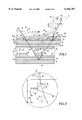
- FIG. 1 is a cross-sectional view of a first embodiment of an optical display device
- FIG. 2 is an enlarged view of the circular region labeled 2 in FIG. 1;
- FIG. 3 is an enlarged view of the circular region labeled 3 in FIG. 1;
- FIG. 4 is a plot depicting a simplified, illustrative light path of the optical display device.
- FIG. 5 is a plot depicting the relationship between illumination angle or first angle of the incident light and a preferred viewing angle of the optical display device
- FIG. 6 is a cross-sectional view of a second embodiment of the optical display device.
- FIG. 7 is a perspective view of a first embodiment of a prismatic film for use in the optical display device.
- FIG. 8 is a cross-sectional view of the prismatic film as viewed along reference line 8--8 in FIG. 7 in the direction of the arrows.
- FIG. 9 is a perspective view of a secondary embodiment of the prismatic film, which has concave first faces.
- FIG. 10 is a cross-sectional view of the prismatic film as viewed along reference line 10--10 in FIG. 9.
- FIG. 11 is a cross-sectional view of a third embodiment of the prismatic film, which has convex first faces.
- FIG. 12 is a perspective view of a fourth embodiment of prismatic film, which has convex first faces distinct from FIG. 11.
- FIG. 13 is a perspective view of a fifth embodiment of the prismatic film which has convexly and concavely sloped first faces.
- optically coupled refers to elements in optical communication with each other that permit the bi-directional transmission of light in at least one plane.
- the viewing plane 26 refers to an imaginary flat surface defined by a mathematical plane substantially parallel to the cell front 56. In practice, the viewing plane 26 may be coincident with a lens of the display. The viewer views the display by looking toward or into the viewing plane 26.
- light shall refer to a group of light rays represented by a representative ray.
- the representative ray represents the general direction of propagation of an illustrative group of light rays.
- the direction of propagation of incident light 42 may be represented by a representative ray.
- the representative ray is divided into a first section 100, a second section 101, a third section 102, a fourth section 103, a fifth section 104, and a sixth section 105.
- the first section 100 of the representative ray is called incident light 42 and the sixth section 105 of the representative ray is called primary exiting light 43.
- the representative ray shown is merely an illustrative example of one possible path of the light interacting with the optical display; other paths are possible. In practice, multiple light rays with different paths typically interact with the optical display.
- the incident light 42 is a portion of ambient light which enters the display through a viewing plane 26 of the display. Such incident light 42 is sometimes called irradiance or illuminance.
- Nonglancing incident light is a light ray that enters the display at an nonglancing angle distinct from the critical angle defined by Snell's law so that no substantial reflection of the light occurs relative to a physical viewing interface 22 of the display coincident with the viewing plane 26.
- Ambient light sources include those sources found in a well-lit room or outdoors. Several ambient sources may irradiate the optical display device 10 from one or more directions and with varying intensity. The ambient light coming from multiple sources and multiple directions may cooperate in illuminating the display for viewing.
- the optically transmissive mode allows sufficient transmission of light through the optical cell 14 to permit a viewer to distinguish the transmissive mode from the nontransmissive mode.
- the optically transmissive mode permits the transmission of light through a particular cell region between the cell front 56 and the cell back 58 such that the light transmitted through the cell is perceptible to a viewer.
- the attenuation of the cell in the transmissive mode is minimized to keep an adequate intensity differential between to the transmissive mode and the nontransmissive mode, yielding a sufficiently contrasted, viewable display for a viewer.
- the optically nontransmissive mode either attenuates or reflects light by an amount sufficient to significantly reduce the intensity of the light traversing the entire cell region. The reduction of intensity of the nontransmissive mode is maximized to keep an adequate intensity differential between the transmissive mode and the nontransmissive mode.
- FIG. 1 depicts an optical display device 10 that comprises a prismatic film 12, optical cell 14, and a reflector 16.
- the display device 10 preferably requires illumination by ambient light through a viewing plane 26 and is viewed through the viewing plane 26.
- the viewing plane 26 may be coincident with a physical viewing interface 22, such as a lens or a planar transparent member.
- the prismatic film 12 includes a prismatic surface 28 and an opposite surface 24 opposite the prismatic surface 28.
- the opposite surface 24 is preferably substantially planar and smooth.
- the viewing plane 26 of the optical display device 10 may coincide with the opposite surface 24 of the prismatic film 12 as best illustrated in FIG. 1. Because the opposite surface 24 is substantially planar, the opposite surface 24 is readily cleaned, dusted, or polished by virtue of its smooth finish so long as the opposite surface 24 is exposed as the physical viewing interface 22 upon an exterior of the display.
- the prismatic surface 28 preferably faces the optical cell 14 as illustrated in FIG. 1, in alternate embodiments the prismatic surface may face away from the optical cell 14 to refract light into the preferential viewing cone 30.
- the prismatic surface 28 comprises a series of prisms or prismatic elements. Each of the prisms has a first face 70 and a second face 72 intersecting the first face 70.
- the first faces 70 are oriented to refract light obliquely intercepting the first faces 70 such that the primary exiting light 43 exiting the display is directed into a preferential viewing cone 30 about an axis normal to the viewing plane 26.
- the light predominately interacts with the first face 70 at oblique angles based upon the nonglancing incident angle of the incident light 42 passing through the viewing plane 26 into the display.
- the first faces 70 are preferably oriented to maximize the refractive interactions of light propagating to and from the optical cell 14 such that an incident angle of incident light 42 relative to the viewing plane 26 is distinct from the magnitude and direction of an exiting angle of the primary exiting light 43.
- the second faces 72 are oriented to minimize refractive, reflective and optical interactions of the light with the second faces 72 so that side lobes of secondary exiting light are minimized.
- the secondary exiting light falls outside the preferential viewing cone 30 and the secondary exiting light rays are called side lobes.
- each prismatic element has a generally triangular cross-section characterized by a base 66 and a height 68.
- Each prism has a longitudinal axis 122 that is oriented perpendicularly to the triangular cross-section and its cross-sectional axis 120.
- the first face 70 has a first slope defining a first prismatic angle 80 with respect to a plane substantially parallel to the opposite surface 24 or the viewing plane 26.
- the first prismatic angle 80 may range from 10 degrees to 60 degrees.
- the prismatic angle 80 optimally has a range from approximately 15 to 25 degrees to refract light interacting with the first face 70 into a preferential viewing cone 30.
- the second face 72 has a second slope defining a second prismatic angle 82 with a plane substantially parallel to the opposite surface 24 or the viewing plane 26.
- the first prismatic angle 80 may be less than or equal to 90 degrees.
- the prismatic angle 80 preferably ranges from 45 degrees to 90 degrees.
- first prismatic angle and the second prismatic angle may have different magnitudes than previously described herein.
- the prismatic film 12 has a maximum thickness 74 defined by the distance between the peak of a prism and the opposite surface 24.
- the prisms have a peak-to-peak spacing between adjacent peaks which is called the pitch 118 of the prismatic surface 28.
- the ratio of the maximum thickness 74 to the pitch 118 is maximized to maximize refractive steering of the incident light 42 into the preferential viewing cone 30.
- the pitch is preferably limited to less than or equal to the pixel size if the prismatic film 12 is located between the viewing interface 22 and the optical cell 14 as shown in FIG. 1.
- the pitch 118 may exceed the pixel size to maximize refractive steering; especially in alternate embodiments where the prismatic film is located behind the optical cell, or between the optical cell and a reflector.
- An illustrative example of the prismatic film 12, which may be used to practice the present invention, has a triangular cross-section defined by a typical base 66 dimension of 200 microns, a typical height 68 of 75 microns, a typical maximum thickness 74 of 150 microns, a front slope angle 80 of approximately 20 degrees, and a rear slope angle 82 of approximately 90 degrees.
- the prismatic film 12 preferably has a height 68 within a range from approximately 60 to 100 microns.
- the prismatic elements optimally adjoin one another in the illustrative example. If magnified sufficiently, the prismatic elements preferably are arranged to give the prismatic surface 28 a jagged profile which resembles the profile of lapped siding on a house.
- the prismatic film 12 has a first refractive index that optimally exceeds 1.4.
- the actual first refractive index depends upon the particular material used to make the prismatic film 12; typically ranges from 1.5 to 1.6 for transparent polymers and polycarbonates. In comparison, air has an index of refraction of approximately 1.
- a transparent adhesive 50 preferably attaches the prismatic film 12 to the optical cell 14.
- the transparent adhesive 50 fills the voids or air-space bounded by the prismatic film 12 and the optical cell 14.
- the transparent adhesive 50 may be made from acrylic resin, acrylate, silicone, epoxy, polyester resin, vinyl ester resin, polycarbonate resin, a plastic, or a polymer. In a preferred embodiment, acrylic resin or acrylate is used for the transparent adhesive 50.
- the transparent adhesive 50 for affixing the prismatic film 12 to the display device 10 has a second refractive index which is different from the first refractive index of the prismatic film 12.
- the first refractive index typically differs from the second refractive index of the transparent adhesive 50 within a range between 0.2 and 0.3, based upon common, commercially available transparent adhesives. More preferably, the first refractive index and the second refractive index differ from one another by greater than 0.3. In the preferred embodiment, the second refractive index is lower than the first refractive index. However, in alternate embodiments the second refractive index may be higher than the first refractive index.
- the optical cell 14 may comprise a liquid crystal cell, a twisted nematic (TN) liquid crystal cell, a super-twisted nematic (STN) liquid crystal cell, a thermally addressable cell, a dynamic-scattering liquid crystal cell, a guest-host effect dichroic dye cell, a chiral nematic display, or the like.
- TN twisted nematic
- STN super-twisted nematic
- the optical cell 14 comprises a twisted nematic effect liquid crystal cell, commonly referred to as a TN or an STN cell.
- the optical cell 14 optimally includes front polarizer 18, front electrode 44, liquid crystal material 38, at least one back electrode 46, and back polarizer 20.
- the front polarizer 18 is optically coupled to the prismatic film 12 and to a cell front 56 of the optical cell 14.
- the front polarizer 18 may comprise a dichroic polarizing film.
- the optical cell 14 has a cell front 56 and a cell back 58.
- the optical cell 14 contains an optically active material, an optically anisotropic material, a liquid crystal material, or the like.
- a liquid crystal material 38 is confined between the cell front 56 and the cell back 58.
- the cell back 58 and the cell front 56 may be made from glass or another transparent material.
- the liquid crystal material may be disposed between sheets of a transparent polymer.
- Liquid crystal material 38 typically is composed of anisometric, organic molecules which tend to have elongated, rod-like shapes. Liquid crystal materials may have nematic or smectic properties, depending upon the arrangement of the molecules of the liquid crystal material. Nematic liquid crystals are commonly used in twisted nematic liquid crystal displays.
- the cell front 56 and the cell back 58 support a front electrode 44 and one or more back electrodes 46, respectively.
- the front electrode 44 and the back electrodes 46 are adjacent to liquid crystal material 38.
- the back electrodes 46 are affixed to inner surface 52 of liquid crystal panel 38.
- the front electrode 44 and the back electrodes 46 are made from substantially transparent conductive materials or metals.
- the front electrode 44 and the back electrodes 46 are preferably made of a transparent indium-tin oxide material. Those of ordinary skill in the art will appreciate that alternate embodiments of the present invention may use reflective, opaque back electrodes.
- the front electrode 44 and the back electrodes 46 may have any shape or size.
- the front electrode 44 and the back electrode 46 may have different shapes.
- the front electrode 44, the back electrodes 46, or both the front electrode 44 and the back electrode 46 are generally shaped as pixels, symbols, characters, or portions of characters to be displayed.
- the front electrode 44 and back electrodes 46 are connected to an external power supply, not shown.
- an alternating current or less preferably a direct current, is applied to the front electrode 44 and at least one back electrode 46 the properties of the liquid crystal change with regards to the liquid crystal material's 38 affect on the propagation of light.
- the back polarizer 20 is optically coupled to the cell back 58 and to reflective means or a reflector 16.
- the reflector 16 preferably comprises a diffuse reflector, a specular reflector, or a transflector.
- Reflector 16 is optically coupled to liquid crystal cell 14, and is effective to receive light emitted from liquid crystal cell 14, and to redirect light back toward cell 14.
- reflector 16 is a metallic gain reflector.
- the surface properties of reflector 16 can be altered in a predetermined manner to effect the amount of diffusion imparted to the ambient light, and in this manner effect the angular distribution of light redirected from the illuminated regions of reflector 16. In this manner, reflector 16 can be a diffuse reflector.
- reflective means signifies more than a merely conventional reflector such as the reflector 16.
- the reflective means may comprise a conventional reflector or transflector coupled to the back of a cell, an optically active material (i.e. liquid crystal material) in a substantially reflective state, or a reflective back electrode.
- the viewing plane 26 of the liquid crystal display device 10 is illuminated by ambient light. Approximately four percent of the incident ambient light is reflected at a glare angle 54, a glancing angle, or range of glare angles. The remaining incident light 42 enters the opposite surface 24 and emerges from the prismatic surface 28 of the prismatic film 12. The prismatic film 12 effectively refracts the ambient light at an angle that is different from the angle that the light would follow without the prismatic film 12.
- front polarizer 18 polarizes the ambient light and transmits linearly polarized light having a first axis of polarization.
- the linearly polarized light from front polarizer 18 is received by liquid crystal cell 14.
- the liquid crystal material 38 may or may not change the polarization state.
- the polarization state is dependent upon the electrical potential applied by front electrode 44 and back electrode 46 to a region of the liquid crystal material 38.
- Back polarizer 20 receives the light from liquid crystal cell 14 and may pass linearly polarized light.
- the linearly polarized light may pass to reflector 16 which redirects the light back towards the back polarizer 20.
- Reflector 16 may redirect the light in a specular manner as a mirror or it may diffuse the light into a preferential diffusion pattern.
- the reflected light passes through back polarizer 20 and is transmitted to cell 14 and subsequently through front polarizer 18.
- Front polarizer 18 emits light that is linearly polarized.
- the linearly polarized light then encounters back face 28 of the prismatic film 12, and emerges through the opposite surface 24, having been steered through a preferential exiting angle 34 falling within a preferential viewing cone 30.
- the prismatic film 12 provides glare avoidance, it is important that the beam steering of the light on the way out of the display does not undo the effect of beam steering of the light on the way into the display.
- the incident light 42 traverses the prismatic film 12 it is refracted. If the net effect of the refractions through the prismatic film 12 does not adequately divert the light from the glare angle 54, the preferential viewing cone 30 will be aligned with the glare, thereby diminishing the effective brightness of the display. Consequently, the beam diversion or offset must be enough to eliminate the deleterious effects of glare.
- the incident light 42 is refracted within the optical display device 10 so that the primary exiting angle has a different magnitude than the incident angle. That is, light entering the optical device at a first angle 31, or the incident angle, has a different magnitude than a tenth angle 78, or the primary exiting angle.
- the angles are preferably measured with respect to normal reference lines or a main axis 90 which is substantially perpendicular to the viewing plane 26. For example, a first reference normal line is associated with the first angle 31 and a second angle 32.
- the direction of the refraction for the light passing through the prismatic film 12 is primarily determined by Snell's law.
- a critical angle i.e. ⁇ crit
- the angle of incidence is greater than the critical angle, the light does not enter the display, but is reflected as glare relative to the viewing plane 26.
- FIG. 1 through FIG. 3 represent typical refractive paths of a representative ray wherein the first index of refraction for the prismatic material is approximately 1.5 and wherein the second index of refraction for an adjoining material is approximately 0.5 less than the first index of refraction.
- the adjoining material is preferably air or a gas-filled volume with a second index of refraction of approximately 1.
- the second index of refraction for the adjoining region the first face 70 may have a lower bound range from 1 to 1.3 depending upon the material used. For a solid adjoining material, the lower practical limit of the second index of refraction is about 1.3
- the refractive paths of the representative ray may differ because of different relative refractive indexes, among other factors.
- the first section 100 makes a first angle 31 (i.e. ⁇ 1) with respect to a first normal reference line 40, which is perpendicular to the opposite surface 24.
- the first section 100 is refracted at an interface between the air and the opposite surface 24 so that the second section 101 makes a second angle 32 (i.e. ⁇ 2) with respect to the first normal reference line 40.
- the second section 101 makes a third angle 33 (i.e. ⁇ 3) with a second normal reference line 41, which is perpendicular to the front slope 70 of a prismatic structure on the prismatic surface 28.
- the second section 101 is refracted at a boundary between the front slope 70 and the transparent adhesive 50.
- the refraction results in a third section 102 making a fourth angle 34 (i.e. ⁇ 4) with respect the second normal reference line 41.
- the third section 102 travels through the optical cell 14 and strikes the reflector 16. As the third section 102 travels through the optical cell 14, the light undergoes a first series of refractive bends (not shown) at various intermediate, parallel refractive interfaces within the display.
- the reflector 16 reflects the third section 102.
- the reflection of the third section 102 from the reflector 16 is designated the fourth section 103.
- the third section 102 makes a fifth angle 35 with respect to a third normal reference line 84, which is substantially perpendicular to a reflecting surface of the reflector 16.
- the fourth section 103 makes a sixth angle 60 with the third normal reference line 84.
- the fifth angle 35 and the sixth angle 60 are preferably substantially equal. In alternate embodiments, diffuse or nonspecular reflectors may yield a fifth angle which has a peak magnitude at a different angle from the sixth angle 60.
- the fourth section 103 As the fourth section 103 travels through the optical cell 14, the light undergoes a second series of refractive bends (not shown) at various intermediate, parallel refractive interfaces within the display. The net affect on the representative ray is that the second series of refractive bends cancels out the first series of refractive bends.
- the fourth section 103 travels through the optical cell 14 and strikes the boundary between the prismatic surface 28 and the transparent adhesive 50.
- the fourth section 103 makes a seventh angle 62 (i.e. ⁇ 7) with a fourth normal reference line 86, which is perpendicular to the effected front slope 70 of the prismatic film 12.
- the fourth section 103 is refracted at the boundary between the prismatic surface 28 and the transparent adhesive 50.
- the refraction results in a fifth section 104 making an eighth angle 64 (i.e. ⁇ 8) with respect to the fourth normal reference line 86.
- the fifth section 104 travels through the prismatic film 12 and strikes the interface between the prismatic surface 28 and the air.
- the fifth section 104 makes a ninth angle 76 (i.e. ⁇ 9) with respect to a fifth normal reference line 88, which is perpendicular to the opposite surface 24.
- the fifth section 104 is refracted at the boundary between the opposite surface 24 and the air.
- the refraction results in a sixth section 105 making a tenth angle 78 (i.e. ⁇ 10)with respect to the fifth normal reference line 88.
- FIG. 4 simplifies the light path 112 through the optical device that was previously illustrated in FIG. 1 through FIG. 3.
- the prismatic film 12, the cell 14 and the reflector 16 optically cooperate to form an illustrative light path 112 for incident light 116 illuminating the opposite surface 24 at an incident angle 114 relative to a main axis 90 or an axis parallel to the main axis 90. If the details of the refractions at the interfaces of the prismatic film 12 are ignored for explanatory purposes, the light path 112 may simplified into a primary segment 92, a secondary segment 94, and a tertiary segment 96.
- the primary segment 92 propagates from the prismatic film 12 toward the reflector 16 at a primary angular measure 106 relative to the main axis 90.
- the primary angular measure 106 is related to the incident angle 114 by a sinusoidal function, based upon Snell's law.
- the secondary segment 94 propagates from the reflector 16 toward the prismatic film 12 at a secondary angular measure 108 approximately equal in magnitude and opposite in direction with respect to the primary angular measure 106.
- the tertiary segment 96 propagates away from the opposite surface 24 at a tertiary angular measure 110 relative to the main axis 90.
- the tertiary angular measure 110 tends to be distinct or is distinct from the incident angle 114 to contribute to the reduction of glare.
- FIG. 5 shows an illustrative plot of incident angles of incident light 42 versus the primary exiting angle of the primary exiting light 43 for various constant values of front slope angles of the prismatic film 12.
- the incident angles or illumination angles are shown on the horizontal axis 400 in degrees measured with respect to the first normal reference line 40.
- the primary exiting angles are shown on the vertical axis 402 in degrees measured with respect to the fifth normal reference line 88.
- the primary exiting angle may be referred to as a viewing angle falling within a viewing angle range.
- the front slope angles are shown as a series of curves 404 with constant front slope angle values ranging from negative ten to negative forty degrees and from positive ten to positive forty degrees.
- the preferential viewing cone 30 is assumed to be a constant value regardless of the incident angle and exiting angle.
- the preferential viewing cone 30 is assumed to be from approximately zero degrees to eight degrees, with zero degrees being substantially perpendicular to the plane of the opposite surface 24.
- the rectangular region in FIG. 5 surrounds an illustrative, preferred operating point 405 for the prismatic film 12 incorporated into the optical device.
- the exiting angle is approximately five degrees at a preferred operating point 405.
- the exiting angle falls within the preferential viewing cone 30.
- the range of exiting angles is commensurate with the range of the preferential viewing cone 30 to provide maximum perceived brightness of the display by a user.
- FIG. 6 shows a cross-sectional view of a second embodiment of the optical display device 210.
- the second embodiment of FIG. 6 is similar to the first embodiment in FIG. 1 through FIG. 3, except the second embodiment has spacers 152 extending from the prismatic surface 128.
- the spacers 152 may comprise stand-offs that cooperate with the optical cell 14 to provide a gap 150 between the prismatic film 212 and the optical cell 14.
- the gap 150 is preferably filled with a gas or a mixture of gases, such as air. Consequently, the transparent adhesive 50 of the first embodiment may be eliminated if the prismatic surface 128 is equipped with appropriate spacers 152 or supports embossed into the prismatic film 212.
- the spacers 152 must provide sufficient rigidity to prevent any damage or permanent deformation of the prismatic film 212.
- the spacers 152 allow the gap 150 or space to bound the prismatic surface 128.
- the gap 150 contains a gas or a mixture of gases with a suitable refractive index with respect to the first refractive index to practice the present invention.
- the gap 150 preferably contains air if the first refractive index equals or exceeds 1.4.
- the spacers 152 are optimally implemented by including first prisms on the prismatic film 212, which have greater heights the remaining second prisms on the prismatic film. While the spacers 152 are integrated into the prismatic film 212, in alternate embodiments the spacers may be separate or distinct from the prismatic film.
- the prismatic film may be supported by placing the peaks of the prisms in contact with the optical cell such that air spaces only adjoin discontinuous regions of the prismatic film, rather the entire prismatic surface.
- FIG. 7 and FIG. 8 illustrate the first embodiment of the prismatic film 12 for the optical display.
- the first face 70 is substantially rectilinearly sloped.
- the flat or rectilinear shape produces a generally preferential conical viewing cone 30 with a generally circular cross section, which is usually parallel to the viewing plane 26.
- the first face may be convexly or concavely curved or sloped along the cross-sectional axis 120 of the prisms to manipulate the shape and scope of the preferential viewing cone as desired for improved visibility of the display.
- the preferential viewing cone may be manipulated to change the circular cross section of the preferential viewing cone to an elliptical cross section, which is usually parallel to the viewing plane 26.
- the elliptical cross section has a major and a minor axis, which are perpendicular to one another.
- the minor axis represents a diminished viewing breadth of the preferential viewing cone, while the major axis represents an enhanced viewing breadth of the preferential viewing cone.
- FIGS. 9 and 10 illustrate a secondary embodiment of the prismatic film 312 in which the prismatic film 312 has first faces 370 that are concavely curved to produce a semi-conical viewing cone with a generally elliptical cross section.
- the first face 370 of each prism is concavely curved along the cross-sectional axis 120 of the prisms. If the first slope of the first face 370 is concavely curved, the viewing cone may be vertically compressed, so long as the cross-sectional axis 120 of the prisms is parallel with or coincident with the vertical axis of the viewing plane 26.
- the vertical axis is vertical relative to a viewer's perspective, if the display is oriented appropriately for viewing.
- FIG. 11 shows a third embodiment of the prismatic film 412 in which the first face 470 is convexly sloped along the cross-sectional axis of the prisms 120. If the cross-sectional axis 120 of the third embodiment of the prismatic film 412 is parallel to or coincident with the horizontal axis of the viewing plane, the preferential viewing cone may be horizontally expanded.
- FIG. 12 illustrates a fourth embodiment of the prismatic film 512 in which the first face 570 is convexly sloped along the longitudinal axis 122 of the prisms.
- the viewing cone may be horizontally expanded, so long as the longitudinal axis 122 is parallel to or coincident with the horizontal axis of the viewing plane 26.
- the horizontal axis is horizontal relative to a viewer's perspective.
- FIG. 13 illustrates a fifth embodiment of the prismatic film 612 in which the first face 670 is both concavely and convexly sloped.
- the second face is concave and has an undercut appearance (i.e.
- the prismatic film may be equipped with prismatic surfaces on two opposing sides to increase the refractive properties of the prismatic film. Any of the foregoing embodiments of the prismatic film may be substituted for the first embodiment of the prismatic film 12 illustrated in FIG. 1, taking care to mount the prismatic film appropriately relative to the intended orientation of the display for viewing purposes.
- the prismatic film may be incorporated into a polymer dispersed liquid crystal cell, commonly referred to as a PDLC cell.
- the prismatic film may be optically coupled to a polymer dispersed liquid crystal cell.
- the PDLC differs from a TN display in that no polarizers are required if dichroic dye is introduced into the liquid crystal material. In the absence of an electric field of a predetermined strength, the liquid crystal material and dichroic dye contained in the droplets are randomly aligned from one droplet to another, and are effective to absorb most incident light.
- the reflective means of a PDLC is preferably a colored gain reflector.
- the colored gain reflector is a frequency selective reflector, which may only reflect light of a particular color.
- the prismatic film may be incorporated into a heterogeneously aligned liquid crystal display, commonly referred to as a reflective optically compensated bend cell.
- the prismatic film may be optically coupled to the optically compensated bend cell between the cell and its viewing interface.
- a display is described in detail by "A Bright Reflective LCD Using Optically Compensated Bend Cell with Gray Scale Capability and Fast Response Speed", Uchida, T., Ishinabe, T., Suzuki, M., SID '96 Digest, Vol 27, pg 31-34), which is incorporated herein by reference.
- the heterogeneously aligned liquid crystal display includes only a front polarizer and has a reflective back electrode. While a front electrode is formed of a transparent indium-tin oxide material, a back electrode is formed of a metallic film, such as copper, nickel, chrome or aluminum. Consequently, back electrode functions both as a reflector and an electrode for applying an electric field to the liquid crystal material.
- the prismatic film may be incorporated into a cholesteric liquid crystal display.
- the prismatic film may be optically coupled to the cholesteric liquid crystal cell between its viewing interface and the cell.
- Commercially available cholesteric displays are sold under the trade names Cholesteric Liquid Crystal Display or ChLCD, Polymer Stabilized Cholesteric Texture Display or PSCT, and Polymer Free Cholesteric Texture Display or PFCT by KDS Company (Kent Ohio) or under the trade name Fast-Response Multistable Liquid Crystal Display or FMLCD by ADS Co. (Richardson, Tex.).
- Cholesteric displays differ from twisted nematic displays in that the liquid crystal layer in a cholesteric display may be used to selectively reflect a portion of the ambient light of a predetermined color band, and transmit the remaining light, or to transmit all light.
- the cholesteric liquid crystal cell may have a chiral nematic phase effective to reflect light.
- a predetermined amount of diffusion is added to the reflected ambient light by the liquid crystal layer.
- liquid crystal layer functions as a colored gain reflector and diffuser.
- a backing layer is effective to absorb a portion of the light transmitted through liquid crystal layer.
- the prismatic film may be optically coupled to a light modulating cell, such as a guest-host device, as described in "Guest-host devices using anisotropic dyes" Scheffer, T. J., Philosophical Transactions of the Royal Society of London, Vol 309, pg 189-201, 1983, which is incorporated herein by reference.
- the prismatic film may be optically coupled to a light modulating cell, which is an electrically controlled birefringence cell (ECB).
- ECB electrically controlled birefringence cell
- Such a device is available from Varitronix under the trade name "Color-Coded STN", from Seiko Instruments under the trade name “ECB Color LCD”, or from Optrex under the trade name "Super Reflector Color (SRC)".
- reflective light modulating cells serve to illustrate possible reflective light modulating cells.
- Those skilled in the art will appreciate that other reflective light modulating cells can be employed with the present device. Many of these cells are described in "Reflective LCDs for Low Power Systems", Uchida, T., SID '96 Digest, Vol 27, pg 31-34, which is incorporated herein by reference.
- Such reflective light modulating cells include, but are not limited to other nematic liquid crystal cells such as pi cells, other non-nematic liquid crystal cells such as surface-stabilized ferroelectric liquid crystal cells, anti-ferroelectric liquid crystal cells, and other non-liquid crystal cells such as electrochromic cells, electrophoretic cells, suspended particle cells, and thermally addressable cells.
- the present invention provides a liquid crystal display device that uses ambient light for device illumination and utilizes no back light. Consequently, the device consumes less power than a device illuminated by a back light. Further, the apparent brightness of the display device is greatly increased from the offsetting of the exiting angle from the incident angle. In addition, the apparent contrast of the display may be improved by offsetting the exiting angle from the incident angle. This offset is accomplished by the use of a prismatic film, which refracts light entering the display device at an incident angle; and eventually results in light exiting the display device at an exiting angle. The incident angle is different from the exiting angle. In this manner, the brightest output angle of the display is offset from the glare angle, thereby potentially providing an enhanced contrast and brighter display device.
Abstract
Description
Claims (37)
Priority Applications (1)
| Application Number | Priority Date | Filing Date | Title |
|---|---|---|---|
| US09/040,047 US6166787A (en) | 1998-03-17 | 1998-03-17 | Optical display device having prismatic film for enhanced viewing |
Applications Claiming Priority (1)
| Application Number | Priority Date | Filing Date | Title |
|---|---|---|---|
| US09/040,047 US6166787A (en) | 1998-03-17 | 1998-03-17 | Optical display device having prismatic film for enhanced viewing |
Publications (1)
| Publication Number | Publication Date |
|---|---|
| US6166787A true US6166787A (en) | 2000-12-26 |
Family
ID=21908801
Family Applications (1)
| Application Number | Title | Priority Date | Filing Date |
|---|---|---|---|
| US09/040,047 Expired - Lifetime US6166787A (en) | 1998-03-17 | 1998-03-17 | Optical display device having prismatic film for enhanced viewing |
Country Status (1)
| Country | Link |
|---|---|
| US (1) | US6166787A (en) |
Cited By (42)
| Publication number | Priority date | Publication date | Assignee | Title |
|---|---|---|---|---|
| US20020021827A1 (en) * | 2000-08-18 | 2002-02-21 | Cross Match Technologies, Inc. | Fingerprint scanner auto-capture system and method |
| WO2002088878A2 (en) * | 2001-04-26 | 2002-11-07 | Cross Match Technologies, Inc. | Silicone rubber surfaces for biometric print tir prisms |
| US20030038755A1 (en) * | 2001-08-16 | 2003-02-27 | E Ink Corporation | Light modulation by frustration of total internal reflection |
| WO2003023505A2 (en) * | 2001-09-11 | 2003-03-20 | Microsharp Corporation Limited | Anti-reflective visual display arrangement |
| US6636285B2 (en) * | 2001-11-01 | 2003-10-21 | Motorola, Inc. | Reflective liquid crystal display with improved contrast |
| US20030223216A1 (en) * | 2002-05-28 | 2003-12-04 | Emmons Robert M. | Multifunctional optical assembly |
| US6678019B2 (en) * | 2000-09-27 | 2004-01-13 | Sharp Kabushiki Kaisha | LCD including light divergent element at front of display panel |
| US6801276B1 (en) * | 1998-04-24 | 2004-10-05 | 3M Innovative Properties Company | Optical component with a structured element |
| US20050088403A1 (en) * | 1998-09-03 | 2005-04-28 | Semiconductor Energy Laboratory Co., Ltd. | Electronic device with liquid crystal display |
| US20050122559A1 (en) * | 2003-12-09 | 2005-06-09 | Reboa Paul F. | Light modulator |
| US20050243300A1 (en) * | 2004-04-29 | 2005-11-03 | Pate Michael A | Reflective optical assembly |
| US20050271348A1 (en) * | 2004-06-02 | 2005-12-08 | Hsin-Hsin Huang Hsu | Prism sheet for a backlight module |
| US20060170906A1 (en) * | 2002-01-17 | 2006-08-03 | Cross Match Technologies, Inc. | Systems and methods for illuminating a platen in a print scanner |
| US20060238679A1 (en) * | 2005-04-26 | 2006-10-26 | Samsung Electronics Co., Ltd. | Display device |
| US20070024781A1 (en) * | 2005-07-30 | 2007-02-01 | Samsung Electronics Co., Ltd. | Polarization compensation film, display panel assembly and display device having the same |
| US20070109622A1 (en) * | 2003-09-30 | 2007-05-17 | Canon Kabushiki Kaisha | Display apparatus |
| US20070189038A1 (en) * | 2002-05-28 | 2007-08-16 | 3M Innovative Properties Company | Multifunctional optical assembly |
| US20080007677A1 (en) * | 2004-06-15 | 2008-01-10 | Masashi Enomoto | Optical Film, Liquid Crystal Panel, And Liquid Crystal Display Apparatus |
| DE102007011560A1 (en) * | 2007-03-02 | 2008-09-04 | Seereal Technologies S.A. | Device for minimizing the bending dispersion in light modulators comprises a refractive optical element assigned to a light modulator |
| US20090201570A1 (en) * | 2008-02-08 | 2009-08-13 | Raytheon Company | Electrophoretic Light Modulator |
| US20090231245A1 (en) * | 2008-03-11 | 2009-09-17 | Craig Lin | Luminance enhancement structure for reflective display devices |
| US20100109988A1 (en) * | 2008-10-31 | 2010-05-06 | Au Optronics Corporation | Display Apparatus |
| US20100141573A1 (en) * | 2008-12-05 | 2010-06-10 | Craig Lin | Luminance enhancement structure with moire reducing design |
| US20100177396A1 (en) * | 2009-01-13 | 2010-07-15 | Craig Lin | Asymmetrical luminance enhancement structure for reflective display devices |
| US20100182351A1 (en) * | 2009-01-22 | 2010-07-22 | Craig Lin | Luminance enhancement structure with varying pitches |
| US20100220381A1 (en) * | 2009-02-27 | 2010-09-02 | Raytheon Company | Multilayer Light Modulator |
| US20100271407A1 (en) * | 2009-04-22 | 2010-10-28 | Andrew Ho | Reflective display devices with luminance enhancement film |
| US20110057927A1 (en) * | 2008-03-11 | 2011-03-10 | Craig Lin | Luminance enhancement structure for reflective display devices |
| US8073209B2 (en) | 2002-01-17 | 2011-12-06 | Cross Match Technologies, Inc | Biometric imaging system and method |
| US20120087012A1 (en) * | 2009-07-28 | 2012-04-12 | Sharp Kabushiki Kaisha | Optical Film, Method For Producing Same, And Method For Controlling Optical Characteristics Of Same |
| US20120307178A1 (en) * | 2011-05-02 | 2012-12-06 | University Of Central Florida | Display device |
| US8456589B1 (en) | 2009-07-27 | 2013-06-04 | Sipix Imaging, Inc. | Display device assembly |
| US8797633B1 (en) | 2009-07-23 | 2014-08-05 | Sipix Imaging, Inc. | Display device assembly and manufacture thereof |
| US8905613B2 (en) | 2012-06-26 | 2014-12-09 | Au Optronics Corporation | Display device and display system combined thereof |
| US20170052301A1 (en) * | 2015-08-18 | 2017-02-23 | Apple Inc. | Display Backlight with an Optical Film |
| US9593824B2 (en) | 2012-06-26 | 2017-03-14 | Au Optronics Corporation | Display device and display system combined thereof |
| US9904107B2 (en) * | 2016-05-31 | 2018-02-27 | Hon Hai Precision Industry Co., Ltd. | Optical film and display device with narrow frame |
| CN107942512A (en) * | 2016-10-13 | 2018-04-20 | 成都理想境界科技有限公司 | A kind of smooth adjustment unit, light regulator part and head-wearing display device |
| US20190079333A1 (en) * | 2017-09-11 | 2019-03-14 | Visteon Global Technologies, Inc. | Electronic display with an improved dead-front presentation |
| US10823368B2 (en) * | 2011-10-27 | 2020-11-03 | Sw Technology Innovations, Inc. | Light directing structures |
| JP2021530751A (en) * | 2018-07-27 | 2021-11-11 | エルジー・ケム・リミテッド | A method for manufacturing a viewing angle compensating film, a method for manufacturing a polarizing plate, a viewing angle compensating film, a polarizing plate and a display device including the same. |
| WO2023208035A1 (en) * | 2022-04-28 | 2023-11-02 | 瑞仪(广州)光电子器件有限公司 | Backlight module and display device |
Citations (37)
| Publication number | Priority date | Publication date | Assignee | Title |
|---|---|---|---|---|
| US3752974A (en) * | 1971-12-13 | 1973-08-14 | Coastal Dynamics Corp | Uniform illumination with edge lighting |
| US4011001A (en) * | 1974-03-15 | 1977-03-08 | Kabushiki Kaisha Daini Seikosha | Liquid crystal device |
| US4017155A (en) * | 1973-09-07 | 1977-04-12 | Kabushiki Kaisha Daini Seikosha | Liquid crystal display device |
| US4252416A (en) * | 1978-10-23 | 1981-02-24 | Societe Suisse Pour L'industrie Horlogere Management Services S.A. | Optical instrument for gathering and distribution of light |
| US4282560A (en) * | 1979-01-15 | 1981-08-04 | A.C.A. Products, Inc. | Light distributor |
| US4573766A (en) * | 1983-12-19 | 1986-03-04 | Cordis Corporation | LED Staggered back lighting panel for LCD module |
| US4726662A (en) * | 1985-09-24 | 1988-02-23 | Talig Corporation | Display including a prismatic lens system or a prismatic reflective system |
| US4737896A (en) * | 1985-07-23 | 1988-04-12 | Canon Kabushiki Kaisha | Illumination device |
| US4799137A (en) * | 1987-03-24 | 1989-01-17 | Minnesota Mining And Manufacturing Company | Reflective film |
| US4798448A (en) * | 1988-02-16 | 1989-01-17 | General Electric Company | High efficiency illumination system for display devices |
| US4822145A (en) * | 1986-05-14 | 1989-04-18 | Massachusetts Institute Of Technology | Method and apparatus utilizing waveguide and polarized light for display of dynamic images |
| US4874228A (en) * | 1987-03-24 | 1989-10-17 | Minnesota Mining And Manufacturing Company | Back-lit display |
| US4896953A (en) * | 1988-08-08 | 1990-01-30 | Minnesota Mining And Manufacturing Company | Anamorphic wide angle safety lens |
| US4929062A (en) * | 1988-11-02 | 1990-05-29 | Motorola, Inc. | Light guide for LCD |
| US4975808A (en) * | 1989-10-02 | 1990-12-04 | Motorola, Inc. | Backlighting apparatus |
| US4989125A (en) * | 1988-05-10 | 1991-01-29 | Minnesota Mining And Manufacturing Company | Reflector using fresnel-type structures having a plurality of active faces |
| US5005108A (en) * | 1989-02-10 | 1991-04-02 | Lumitex, Inc. | Thin panel illuminator |
| US5029060A (en) * | 1990-07-17 | 1991-07-02 | Minnesota Mining And Manufacturing Company | Uniform intensity profile catadioptric lens |
| US5040878A (en) * | 1990-01-26 | 1991-08-20 | Dimension Technologies, Inc. | Illumination for transmissive displays |
| US5040883A (en) * | 1989-10-30 | 1991-08-20 | Minnesota Mining And Manufacturing Company | Light fixture with beam shaping lens |
| US5070431A (en) * | 1989-08-03 | 1991-12-03 | Pioneer Electronic Corporation | Display board illuminating device for passive displays |
| US5126882A (en) * | 1987-11-12 | 1992-06-30 | Mitsubishi Rayon Co., Ltd. | Plane light source unit |
| US5136479A (en) * | 1990-06-19 | 1992-08-04 | E-Systems, Inc. | Device and method for creating an areal light source |
| US5190370A (en) * | 1991-08-21 | 1993-03-02 | Minnesota Mining And Manufacturing Company | High aspect ratio lighting element |
| US5477239A (en) * | 1993-11-12 | 1995-12-19 | Dell Usa, L.P. | Front lighting system for liquid crystal display |
| US5557433A (en) * | 1994-02-28 | 1996-09-17 | Nec Corporation | Transmissive liquid crystal display having prism lens film for light illumination and wave lens film for light diffusion |
| US5600456A (en) * | 1994-09-01 | 1997-02-04 | Nec Corporation | Transmission liquid crystal display with a reduced dependency of a display quality upon a visual angle |
| US5608550A (en) * | 1994-06-24 | 1997-03-04 | Minnesota Mining And Manufacturing Company | Front-lit liquid crystal display having brightness enhancing film with microridges which directs light through the display to a reflector |
| US5629784A (en) * | 1994-04-12 | 1997-05-13 | Ois Optical Imaging Systems, Inc. | Liquid crystal display with holographic diffuser and prism sheet on viewer side |
| US5671028A (en) * | 1994-05-11 | 1997-09-23 | Sharp Kabushiki Kaisha | Liquid crystal display including a control member for providing a transparent visual range within a predetermined viewing angle and an opaque visual range outside the predetermined viewing angle |
| US5706066A (en) * | 1995-10-16 | 1998-01-06 | Sharp Kabushiki Kaisha | Deflecting device and projection-type display unit using same |
| US5724111A (en) * | 1995-06-13 | 1998-03-03 | Nec Corporation | Reflective LCD having a light scattering means formed on an electrode side surface of a counter substrate |
| US5797668A (en) * | 1996-04-04 | 1998-08-25 | Dai Nippon Printing Co., Ltd. | Surface illumination device suitable for a backlit display |
| US5914759A (en) * | 1996-02-07 | 1999-06-22 | Nitto Jushi Kogyo Kabushiki Kaisha | Surface light source device, liquid crystal display and asymmetric prism sheet |
| US5917664A (en) * | 1996-02-05 | 1999-06-29 | 3M Innovative Properties Company | Brightness enhancement film with soft cutoff |
| US5940152A (en) * | 1997-05-01 | 1999-08-17 | Wilson; Stephen S. | Dual-fresnel field lens for a single-panel LCD projection system |
| US5949506A (en) * | 1998-04-01 | 1999-09-07 | Ois Optical Imaging Systems, Inc. | LCD with diffuser having diffusing particles therein located between polarizers |
-
1998
- 1998-03-17 US US09/040,047 patent/US6166787A/en not_active Expired - Lifetime
Patent Citations (37)
| Publication number | Priority date | Publication date | Assignee | Title |
|---|---|---|---|---|
| US3752974A (en) * | 1971-12-13 | 1973-08-14 | Coastal Dynamics Corp | Uniform illumination with edge lighting |
| US4017155A (en) * | 1973-09-07 | 1977-04-12 | Kabushiki Kaisha Daini Seikosha | Liquid crystal display device |
| US4011001A (en) * | 1974-03-15 | 1977-03-08 | Kabushiki Kaisha Daini Seikosha | Liquid crystal device |
| US4252416A (en) * | 1978-10-23 | 1981-02-24 | Societe Suisse Pour L'industrie Horlogere Management Services S.A. | Optical instrument for gathering and distribution of light |
| US4282560A (en) * | 1979-01-15 | 1981-08-04 | A.C.A. Products, Inc. | Light distributor |
| US4573766A (en) * | 1983-12-19 | 1986-03-04 | Cordis Corporation | LED Staggered back lighting panel for LCD module |
| US4737896A (en) * | 1985-07-23 | 1988-04-12 | Canon Kabushiki Kaisha | Illumination device |
| US4726662A (en) * | 1985-09-24 | 1988-02-23 | Talig Corporation | Display including a prismatic lens system or a prismatic reflective system |
| US4822145A (en) * | 1986-05-14 | 1989-04-18 | Massachusetts Institute Of Technology | Method and apparatus utilizing waveguide and polarized light for display of dynamic images |
| US4874228A (en) * | 1987-03-24 | 1989-10-17 | Minnesota Mining And Manufacturing Company | Back-lit display |
| US4799137A (en) * | 1987-03-24 | 1989-01-17 | Minnesota Mining And Manufacturing Company | Reflective film |
| US5126882A (en) * | 1987-11-12 | 1992-06-30 | Mitsubishi Rayon Co., Ltd. | Plane light source unit |
| US4798448A (en) * | 1988-02-16 | 1989-01-17 | General Electric Company | High efficiency illumination system for display devices |
| US4989125A (en) * | 1988-05-10 | 1991-01-29 | Minnesota Mining And Manufacturing Company | Reflector using fresnel-type structures having a plurality of active faces |
| US4896953A (en) * | 1988-08-08 | 1990-01-30 | Minnesota Mining And Manufacturing Company | Anamorphic wide angle safety lens |
| US4929062A (en) * | 1988-11-02 | 1990-05-29 | Motorola, Inc. | Light guide for LCD |
| US5005108A (en) * | 1989-02-10 | 1991-04-02 | Lumitex, Inc. | Thin panel illuminator |
| US5070431A (en) * | 1989-08-03 | 1991-12-03 | Pioneer Electronic Corporation | Display board illuminating device for passive displays |
| US4975808A (en) * | 1989-10-02 | 1990-12-04 | Motorola, Inc. | Backlighting apparatus |
| US5040883A (en) * | 1989-10-30 | 1991-08-20 | Minnesota Mining And Manufacturing Company | Light fixture with beam shaping lens |
| US5040878A (en) * | 1990-01-26 | 1991-08-20 | Dimension Technologies, Inc. | Illumination for transmissive displays |
| US5136479A (en) * | 1990-06-19 | 1992-08-04 | E-Systems, Inc. | Device and method for creating an areal light source |
| US5029060A (en) * | 1990-07-17 | 1991-07-02 | Minnesota Mining And Manufacturing Company | Uniform intensity profile catadioptric lens |
| US5190370A (en) * | 1991-08-21 | 1993-03-02 | Minnesota Mining And Manufacturing Company | High aspect ratio lighting element |
| US5477239A (en) * | 1993-11-12 | 1995-12-19 | Dell Usa, L.P. | Front lighting system for liquid crystal display |
| US5557433A (en) * | 1994-02-28 | 1996-09-17 | Nec Corporation | Transmissive liquid crystal display having prism lens film for light illumination and wave lens film for light diffusion |
| US5629784A (en) * | 1994-04-12 | 1997-05-13 | Ois Optical Imaging Systems, Inc. | Liquid crystal display with holographic diffuser and prism sheet on viewer side |
| US5671028A (en) * | 1994-05-11 | 1997-09-23 | Sharp Kabushiki Kaisha | Liquid crystal display including a control member for providing a transparent visual range within a predetermined viewing angle and an opaque visual range outside the predetermined viewing angle |
| US5608550A (en) * | 1994-06-24 | 1997-03-04 | Minnesota Mining And Manufacturing Company | Front-lit liquid crystal display having brightness enhancing film with microridges which directs light through the display to a reflector |
| US5600456A (en) * | 1994-09-01 | 1997-02-04 | Nec Corporation | Transmission liquid crystal display with a reduced dependency of a display quality upon a visual angle |
| US5724111A (en) * | 1995-06-13 | 1998-03-03 | Nec Corporation | Reflective LCD having a light scattering means formed on an electrode side surface of a counter substrate |
| US5706066A (en) * | 1995-10-16 | 1998-01-06 | Sharp Kabushiki Kaisha | Deflecting device and projection-type display unit using same |
| US5917664A (en) * | 1996-02-05 | 1999-06-29 | 3M Innovative Properties Company | Brightness enhancement film with soft cutoff |
| US5914759A (en) * | 1996-02-07 | 1999-06-22 | Nitto Jushi Kogyo Kabushiki Kaisha | Surface light source device, liquid crystal display and asymmetric prism sheet |
| US5797668A (en) * | 1996-04-04 | 1998-08-25 | Dai Nippon Printing Co., Ltd. | Surface illumination device suitable for a backlit display |
| US5940152A (en) * | 1997-05-01 | 1999-08-17 | Wilson; Stephen S. | Dual-fresnel field lens for a single-panel LCD projection system |
| US5949506A (en) * | 1998-04-01 | 1999-09-07 | Ois Optical Imaging Systems, Inc. | LCD with diffuser having diffusing particles therein located between polarizers |
Non-Patent Citations (2)
| Title |
|---|
| Hiyama, et al., "P-45: High-Performance Reflective STN-LCD with a Blazed Reflector", SID 97 Digest, pp. 655-658. |
| Hiyama, et al., P 45: High Performance Reflective STN LCD with a Blazed Reflector , SID 97 Digest, pp. 655 658. * |
Cited By (80)
| Publication number | Priority date | Publication date | Assignee | Title |
|---|---|---|---|---|
| US6801276B1 (en) * | 1998-04-24 | 2004-10-05 | 3M Innovative Properties Company | Optical component with a structured element |
| US20090046218A1 (en) * | 1998-09-03 | 2009-02-19 | Semiconductor Energy Laboratory Co., Ltd. | Electronic device with liquid crystal display |
| US7916130B2 (en) | 1998-09-03 | 2011-03-29 | Semiconductor Energy Laboratory Co., Ltd. | Electronic device with liquid crystal display |
| US20050088403A1 (en) * | 1998-09-03 | 2005-04-28 | Semiconductor Energy Laboratory Co., Ltd. | Electronic device with liquid crystal display |
| US8368845B2 (en) | 1998-09-03 | 2013-02-05 | Semiconductor Energy Laboratory Co., Ltd. | Electronic device with liquid crystal display |
| US20090058795A1 (en) * | 1998-09-03 | 2009-03-05 | Semiconductor Energy Laboratory Co., Ltd. | Electronic device with liquid crystal display |
| US8547322B2 (en) | 1998-09-03 | 2013-10-01 | Semiconductor Energy Laboratory Co., Ltd. | Electronic device with liquid crystal display |
| US7262754B1 (en) * | 1998-09-03 | 2007-08-28 | Semiconductor Energy Laboratory Co., Ltd. | Electronic device with liquid crystal display |
| US7657067B2 (en) | 2000-08-18 | 2010-02-02 | Cross Match Technologies, Inc. | Fingerprint scanner auto-capture system and method |
| US20020021827A1 (en) * | 2000-08-18 | 2002-02-21 | Cross Match Technologies, Inc. | Fingerprint scanner auto-capture system and method |
| US6678019B2 (en) * | 2000-09-27 | 2004-01-13 | Sharp Kabushiki Kaisha | LCD including light divergent element at front of display panel |
| WO2002088878A3 (en) * | 2001-04-26 | 2003-07-10 | Cross Match Technologies Inc | Silicone rubber surfaces for biometric print tir prisms |
| WO2002088878A2 (en) * | 2001-04-26 | 2002-11-07 | Cross Match Technologies, Inc. | Silicone rubber surfaces for biometric print tir prisms |
| US6819471B2 (en) | 2001-08-16 | 2004-11-16 | E Ink Corporation | Light modulation by frustration of total internal reflection |
| US20030038755A1 (en) * | 2001-08-16 | 2003-02-27 | E Ink Corporation | Light modulation by frustration of total internal reflection |
| WO2003023505A3 (en) * | 2001-09-11 | 2003-05-30 | Microsharp Corp Ltd | Anti-reflective visual display arrangement |
| WO2003023505A2 (en) * | 2001-09-11 | 2003-03-20 | Microsharp Corporation Limited | Anti-reflective visual display arrangement |
| US6636285B2 (en) * | 2001-11-01 | 2003-10-21 | Motorola, Inc. | Reflective liquid crystal display with improved contrast |
| US20060170906A1 (en) * | 2002-01-17 | 2006-08-03 | Cross Match Technologies, Inc. | Systems and methods for illuminating a platen in a print scanner |
| US8073209B2 (en) | 2002-01-17 | 2011-12-06 | Cross Match Technologies, Inc | Biometric imaging system and method |
| US20060083478A1 (en) * | 2002-05-28 | 2006-04-20 | 3M Innovative Properties Company | Multifunctional optical assembly |
| US7010212B2 (en) | 2002-05-28 | 2006-03-07 | 3M Innovative Properties Company | Multifunctional optical assembly |
| SG144748A1 (en) * | 2002-05-28 | 2008-08-28 | 3M Innovative Properties Co | Multifunctional optical assembly |
| US7095943B2 (en) | 2002-05-28 | 2006-08-22 | 3M Innovative Properties Company | Multifunctional optical assembly |
| US20060285816A1 (en) * | 2002-05-28 | 2006-12-21 | 3M Innovative Properties Company | Multifunctional Optical Assembly |
| WO2003102642A3 (en) * | 2002-05-28 | 2004-07-22 | 3M Innovative Properties Co | Multifunctional optical assembly |
| US7218831B2 (en) | 2002-05-28 | 2007-05-15 | 3M Innovative Properties Company | Multifunctional optical assembly |
| WO2003102642A2 (en) * | 2002-05-28 | 2003-12-11 | 3M Innovative Properties Company | Multifunctional optical assembly |
| US20070189038A1 (en) * | 2002-05-28 | 2007-08-16 | 3M Innovative Properties Company | Multifunctional optical assembly |
| US20030223216A1 (en) * | 2002-05-28 | 2003-12-04 | Emmons Robert M. | Multifunctional optical assembly |
| SG144747A1 (en) * | 2002-05-28 | 2008-08-28 | 3M Innovative Properties Co | Multifunctional optical assembly |
| US7663799B2 (en) * | 2003-09-30 | 2010-02-16 | Canon Kabushiki Kaisha | Display apparatus |
| US20070109622A1 (en) * | 2003-09-30 | 2007-05-17 | Canon Kabushiki Kaisha | Display apparatus |
| US20050122559A1 (en) * | 2003-12-09 | 2005-06-09 | Reboa Paul F. | Light modulator |
| US6917456B2 (en) | 2003-12-09 | 2005-07-12 | Hewlett-Packard Development Company, L.P. | Light modulator |
| US7055969B2 (en) | 2004-04-29 | 2006-06-06 | Hewlett-Packard Development Company, L.P. | Reflective optical assembly |
| US20050243300A1 (en) * | 2004-04-29 | 2005-11-03 | Pate Michael A | Reflective optical assembly |
| US20050271348A1 (en) * | 2004-06-02 | 2005-12-08 | Hsin-Hsin Huang Hsu | Prism sheet for a backlight module |
| US20080007677A1 (en) * | 2004-06-15 | 2008-01-10 | Masashi Enomoto | Optical Film, Liquid Crystal Panel, And Liquid Crystal Display Apparatus |
| US20060238679A1 (en) * | 2005-04-26 | 2006-10-26 | Samsung Electronics Co., Ltd. | Display device |
| US7502085B2 (en) * | 2005-04-26 | 2009-03-10 | Samsung Electronics Co., Ltd. | Display device having functional transparent plate in prismatic structure on retarder provided on polarizer above display panel assembly |
| US20070024781A1 (en) * | 2005-07-30 | 2007-02-01 | Samsung Electronics Co., Ltd. | Polarization compensation film, display panel assembly and display device having the same |
| DE102007011560A1 (en) * | 2007-03-02 | 2008-09-04 | Seereal Technologies S.A. | Device for minimizing the bending dispersion in light modulators comprises a refractive optical element assigned to a light modulator |
| US20090201570A1 (en) * | 2008-02-08 | 2009-08-13 | Raytheon Company | Electrophoretic Light Modulator |
| US8130441B2 (en) | 2008-02-08 | 2012-03-06 | Raytheon Company | Electrophoretic light modulator |
| US20090231245A1 (en) * | 2008-03-11 | 2009-09-17 | Craig Lin | Luminance enhancement structure for reflective display devices |
| US8395836B2 (en) | 2008-03-11 | 2013-03-12 | Sipix Imaging, Inc. | Luminance enhancement structure for reflective display devices |
| US20110057927A1 (en) * | 2008-03-11 | 2011-03-10 | Craig Lin | Luminance enhancement structure for reflective display devices |
| US8437069B2 (en) | 2008-03-11 | 2013-05-07 | Sipix Imaging, Inc. | Luminance enhancement structure for reflective display devices |
| US20100109988A1 (en) * | 2008-10-31 | 2010-05-06 | Au Optronics Corporation | Display Apparatus |
| US8378940B2 (en) | 2008-10-31 | 2013-02-19 | Au Optronics Corporation | Display apparatus |
| US20100141573A1 (en) * | 2008-12-05 | 2010-06-10 | Craig Lin | Luminance enhancement structure with moire reducing design |
| US8441414B2 (en) | 2008-12-05 | 2013-05-14 | Sipix Imaging, Inc. | Luminance enhancement structure with Moiré reducing design |
| TWI427331B (en) * | 2009-01-13 | 2014-02-21 | Sipix Imaging Inc | Asymmetrical luminance enhancement structure for reflective display devices |
| US20100177396A1 (en) * | 2009-01-13 | 2010-07-15 | Craig Lin | Asymmetrical luminance enhancement structure for reflective display devices |
| US20100182351A1 (en) * | 2009-01-22 | 2010-07-22 | Craig Lin | Luminance enhancement structure with varying pitches |
| US9025234B2 (en) | 2009-01-22 | 2015-05-05 | E Ink California, Llc | Luminance enhancement structure with varying pitches |
| US20100220381A1 (en) * | 2009-02-27 | 2010-09-02 | Raytheon Company | Multilayer Light Modulator |
| US8004747B2 (en) | 2009-02-27 | 2011-08-23 | Raytheon Company | Multilayer light modulator |
| US20110134507A1 (en) * | 2009-02-27 | 2011-06-09 | Raytheon Company | Multilayer Light Modulator |
| US7894123B2 (en) | 2009-02-27 | 2011-02-22 | Raytheon Company | Multilayer light modulator |
| US20100271407A1 (en) * | 2009-04-22 | 2010-10-28 | Andrew Ho | Reflective display devices with luminance enhancement film |
| US8714780B2 (en) | 2009-04-22 | 2014-05-06 | Sipix Imaging, Inc. | Display devices with grooved luminance enhancement film |
| US8797633B1 (en) | 2009-07-23 | 2014-08-05 | Sipix Imaging, Inc. | Display device assembly and manufacture thereof |
| US8456589B1 (en) | 2009-07-27 | 2013-06-04 | Sipix Imaging, Inc. | Display device assembly |
| US20120087012A1 (en) * | 2009-07-28 | 2012-04-12 | Sharp Kabushiki Kaisha | Optical Film, Method For Producing Same, And Method For Controlling Optical Characteristics Of Same |
| US9389340B2 (en) * | 2009-07-28 | 2016-07-12 | Sharp Kabushiki Kaisha | Optical film, method for producing same, and method for controlling optical characteristics of same |
| US8804067B2 (en) * | 2011-05-02 | 2014-08-12 | Au Optronics Corporation | Display device |
| US20120307178A1 (en) * | 2011-05-02 | 2012-12-06 | University Of Central Florida | Display device |
| US10823368B2 (en) * | 2011-10-27 | 2020-11-03 | Sw Technology Innovations, Inc. | Light directing structures |
| US11149919B2 (en) | 2011-10-27 | 2021-10-19 | S.V.V. Technology Innovations, Inc. | Light directing structures |
| US8905613B2 (en) | 2012-06-26 | 2014-12-09 | Au Optronics Corporation | Display device and display system combined thereof |
| US9593824B2 (en) | 2012-06-26 | 2017-03-14 | Au Optronics Corporation | Display device and display system combined thereof |
| US20170052301A1 (en) * | 2015-08-18 | 2017-02-23 | Apple Inc. | Display Backlight with an Optical Film |
| US10571618B2 (en) * | 2015-08-18 | 2020-02-25 | Apple Inc. | Display backlight with an optical film |
| US9904107B2 (en) * | 2016-05-31 | 2018-02-27 | Hon Hai Precision Industry Co., Ltd. | Optical film and display device with narrow frame |
| CN107942512A (en) * | 2016-10-13 | 2018-04-20 | 成都理想境界科技有限公司 | A kind of smooth adjustment unit, light regulator part and head-wearing display device |
| US20190079333A1 (en) * | 2017-09-11 | 2019-03-14 | Visteon Global Technologies, Inc. | Electronic display with an improved dead-front presentation |
| JP2021530751A (en) * | 2018-07-27 | 2021-11-11 | エルジー・ケム・リミテッド | A method for manufacturing a viewing angle compensating film, a method for manufacturing a polarizing plate, a viewing angle compensating film, a polarizing plate and a display device including the same. |
| WO2023208035A1 (en) * | 2022-04-28 | 2023-11-02 | 瑞仪(广州)光电子器件有限公司 | Backlight module and display device |
Similar Documents
| Publication | Publication Date | Title |
|---|---|---|
| US6166787A (en) | Optical display device having prismatic film for enhanced viewing | |
| US5339179A (en) | Edge-lit transflective non-emissive display with angled interface means on both sides of light conducting panel | |
| US5629784A (en) | Liquid crystal display with holographic diffuser and prism sheet on viewer side | |
| CN101075040B (en) | Light source device, display device, terminal device, and transparent/scattering state switching element | |
| JP3460588B2 (en) | Display device and electronic device using the same | |
| USRE44063E1 (en) | Light source device, display device, and terminal device | |
| KR100272875B1 (en) | Diffusion optical guide plate, and backlight source and liquid crystal display apparatus using the same | |
| US6744480B2 (en) | Liquid crystal display device | |
| KR100802761B1 (en) | Liquid-crystal display apparatus | |
| EP1073918B1 (en) | Optical components with self-adhering diffuser | |
| US6144430A (en) | Reflective-type liquid crystal display with single polarizer and an inner metallic reflector | |
| JP3394460B2 (en) | Reflective liquid crystal display | |
| US20010024561A1 (en) | Display device | |
| EP1279064A1 (en) | Transflective display with non-inverting image | |
| WO2005008322A1 (en) | Liquid crystal display unit | |
| JP2001093321A (en) | Lighting device and display using it | |
| KR20110068210A (en) | Transparent display device | |
| KR20000006520A (en) | Liquid crystal display device | |
| JP3381133B2 (en) | Liquid crystal display | |
| JP2651088B2 (en) | LCD panel | |
| US20050206811A1 (en) | Novel optical configurations in high contrast chiral nematic liquid crystal displays | |
| CN100405157C (en) | Spread illuminating apparatus adapted to allow light to exit out from both surfaces of light conductive plate | |
| WO1998032047A1 (en) | Ambient illuminated electro-optic display device | |
| JP2003005181A (en) | Liquid crystal display device | |
| US6674505B1 (en) | Light-modulating cell |
Legal Events
| Date | Code | Title | Description |
|---|---|---|---|
| STCF | Information on status: patent grant |
Free format text: PATENTED CASE |
|
| CC | Certificate of correction | ||
| FPAY | Fee payment |
Year of fee payment: 4 |
|
| FPAY | Fee payment |
Year of fee payment: 8 |
|
| AS | Assignment |
Owner name: MOTOROLA MOBILITY, INC, ILLINOIS Free format text: ASSIGNMENT OF ASSIGNORS INTEREST;ASSIGNOR:MOTOROLA, INC;REEL/FRAME:025673/0558 Effective date: 20100731 |
|
| FPAY | Fee payment |
Year of fee payment: 12 |
|
| AS | Assignment |
Owner name: MOTOROLA MOBILITY LLC, ILLINOIS Free format text: CHANGE OF NAME;ASSIGNOR:MOTOROLA MOBILITY, INC.;REEL/FRAME:029216/0282 Effective date: 20120622 |
|
| AS | Assignment |
Owner name: GOOGLE TECHNOLOGY HOLDINGS LLC, CALIFORNIA Free format text: ASSIGNMENT OF ASSIGNORS INTEREST;ASSIGNOR:MOTOROLA MOBILITY LLC;REEL/FRAME:035377/0001 Effective date: 20141028 |