US6170118B1 - Collection apparatus for use with blower/vacuum units - Google Patents
Collection apparatus for use with blower/vacuum units Download PDFInfo
- Publication number
- US6170118B1 US6170118B1 US08/953,847 US95384797A US6170118B1 US 6170118 B1 US6170118 B1 US 6170118B1 US 95384797 A US95384797 A US 95384797A US 6170118 B1 US6170118 B1 US 6170118B1
- Authority
- US
- United States
- Prior art keywords
- lid
- container
- collection apparatus
- debris
- power unit
- Prior art date
- Legal status (The legal status is an assumption and is not a legal conclusion. Google has not performed a legal analysis and makes no representation as to the accuracy of the status listed.)
- Expired - Lifetime
Links
Images


Classifications
-
- A—HUMAN NECESSITIES
- A47—FURNITURE; DOMESTIC ARTICLES OR APPLIANCES; COFFEE MILLS; SPICE MILLS; SUCTION CLEANERS IN GENERAL
- A47L—DOMESTIC WASHING OR CLEANING; SUCTION CLEANERS IN GENERAL
- A47L9/00—Details or accessories of suction cleaners, e.g. mechanical means for controlling the suction or for effecting pulsating action; Storing devices specially adapted to suction cleaners or parts thereof; Carrying-vehicles specially adapted for suction cleaners
- A47L9/10—Filters; Dust separators; Dust removal; Automatic exchange of filters
- A47L9/14—Bags or the like; Rigid filtering receptacles; Attachment of, or closures for, bags or receptacles
- A47L9/1418—Impermeable dust collecting bags
-
- A—HUMAN NECESSITIES
- A47—FURNITURE; DOMESTIC ARTICLES OR APPLIANCES; COFFEE MILLS; SPICE MILLS; SUCTION CLEANERS IN GENERAL
- A47L—DOMESTIC WASHING OR CLEANING; SUCTION CLEANERS IN GENERAL
- A47L5/00—Structural features of suction cleaners
- A47L5/12—Structural features of suction cleaners with power-driven air-pumps or air-compressors, e.g. driven by motor vehicle engine vacuum
- A47L5/22—Structural features of suction cleaners with power-driven air-pumps or air-compressors, e.g. driven by motor vehicle engine vacuum with rotary fans
- A47L5/36—Suction cleaners with hose between nozzle and casing; Suction cleaners for fixing on staircases; Suction cleaners for carrying on the back
- A47L5/365—Suction cleaners with hose between nozzle and casing; Suction cleaners for fixing on staircases; Suction cleaners for carrying on the back of the vertical type, e.g. tank or bucket type
-
- A—HUMAN NECESSITIES
- A47—FURNITURE; DOMESTIC ARTICLES OR APPLIANCES; COFFEE MILLS; SPICE MILLS; SUCTION CLEANERS IN GENERAL
- A47L—DOMESTIC WASHING OR CLEANING; SUCTION CLEANERS IN GENERAL
- A47L9/00—Details or accessories of suction cleaners, e.g. mechanical means for controlling the suction or for effecting pulsating action; Storing devices specially adapted to suction cleaners or parts thereof; Carrying-vehicles specially adapted for suction cleaners
- A47L9/009—Carrying-vehicles; Arrangements of trollies or wheels; Means for avoiding mechanical obstacles
-
- Y—GENERAL TAGGING OF NEW TECHNOLOGICAL DEVELOPMENTS; GENERAL TAGGING OF CROSS-SECTIONAL TECHNOLOGIES SPANNING OVER SEVERAL SECTIONS OF THE IPC; TECHNICAL SUBJECTS COVERED BY FORMER USPC CROSS-REFERENCE ART COLLECTIONS [XRACs] AND DIGESTS
- Y10—TECHNICAL SUBJECTS COVERED BY FORMER USPC
- Y10S—TECHNICAL SUBJECTS COVERED BY FORMER USPC CROSS-REFERENCE ART COLLECTIONS [XRACs] AND DIGESTS
- Y10S55/00—Gas separation
- Y10S55/03—Vacuum cleaner
Definitions
- the subject invention is generally related to devices for collecting and storing material and debris in an industrial, commercial or residential setting and is specifically directed to a mobile collection system for use with vacuum and blower units for quickly and easily collecting and storing large volumes of bulk material and debris as it is collected.
- Typical industrial vacuum cleaners which include an upright metal canister connected to a vacuum pump are disclosed in U.S. Pat. Nos. 4,723,971 and 4,467,494.
- One disadvantage of this type of industrial vacuum cleaner is its large, bulky design. Vacuum cleaners of such a design are comparatively heavy due to the metal cylinder which forms the receptacle for the debris. Due to their bulk and weight, vacuum machines of such design may also be difficult to maneuver over large areas such as factory floors, worksites and amusement parks. Further, vacuum machines of this type use suction (water-lift) to clean, typically have only 60-80 CFM of air flow, and typically utilize a maximum two inch diameter intake hose which limits the size of bulk debris collected. Also, there is a loss of power when the vacuum intake is extended beyond a few feet of the unit.
- UPKEEPER VOYAGER TURBO TRANSFORMER (R) vacuum machine As shown in U.S. Pat. No. 5,722,110, manufactured by Upkeeper Corporation, the assignee of the subject application.
- the turbo fan technology used in the Upkeeper vacuum machine generates 500 CFM of air flow to clean debris with ease and the air flow works, even at distances of 20-25 feet overhead.
- the Upkeeper vacuum has greatly advanced the art relating to industrial vacuums, it is designed to include a debris receptacle or collection bag which may not be readily suitable for storing extra large volumes of debris. When the bag is full, the operator must turn off the vacuum power and empty the bag before continuing to collect debris. Thus, the clean up process is slowed. While there are prior art vacuum machines designed to provide large receptacles for storing large volumes of debris as it is collected, the prior art machines are awkward, heavy and require a large space for storage of the machine.
- prior art vacuums using 60-80 inches of water lift must have a storage receptacle constructed of a sturdy heavy material such as metal, which require large areas for storage. Without such a sturdy, heavy material, the storage receptacle would implode (collapse) with the 60-80 inches of water lift generated.
- prior art storage receptacles have not been constructed from lightweight materials.
- these prior art vacuums must be constructed so as to maintain a virtual airtight seal since they rely heavily on the 60-80 inches of water for cleaning.
- the prior art vacuum machines are not capable of collecting large bulk debris, such as cans, cups, large scraps of cloth, leather, canvas, plastic, pine cones, leaves and the like.
- the subject invention is directed to a mobile, lightweight, universal collection apparatus or drum kit for use with blower/vacuum units for quickly and easily collecting and storing large amounts of bulky debris, leaves or other lightweight items, yet is readily disassembled for conveniently storing and shipping the apparatus.
- the collection apparatus is specifically designed to include a universal attachment accessory to permit easy and secure attachment of either a blower/vacuum unit and intake hose attachments with large diameter intake capacity for picking up large debris or other items while providing a large mobile receptacle for storage of the debris as it is collected by the unit.
- the subject invention provides a system which utilizes a blower/vacuum unit to clean up large volumes of bulky debris while simultaneously depositing the debris into a large, lightweight, storage container.
- the system is versatile and may utilize a collapsible, transparent, storage container or a standard 55-gallon drum.
- the subject invention provides a quick, easy and economical collection system which eliminates the hassle of frequently removing and emptying the vacuum collection bag when large amounts of debris are collected and eliminates the need for moving debris from a small container to a larger container.
- the collection apparatus includes a large transparent container or receptacle for debris, a transparent, removable lid, a transparent, disposable liner, an intake hose attachment and a base with rollers or wheels for movably supporting the container.
- the removable lid includes an integral filter and may be designed to fit the open top of most containers selected by the user, preferably one having a large storage capacity.
- the lid also includes a power unit connection which may be universally adaptable to different blower/vacuum units for removably mounting such unit on the lid.
- the lid includes an inlet connection which is universally adaptable to fit different accessories for removably attaching a variety of intake hose attachments, having a large diameter intake capability, to the lid.
- debris is drawn into the inlet connection of the container through the intake hose attachment by the blower/vacuum unit and deposited into the internal liner within the container.
- the inclusion of the inlet connection in the lid for collecting material and debris permits the material and debris to be drawn directly into the container thus bypassing the blower/vacuum unit.
- debris does not enter or travel through the impeller of the unit.
- the blower/vacuum unit operates more quietly, saves wear and tear on the impeller and does not shred or disintegrate the debris and materials collected, such as, cloth, leather, packaging materials, styrofoam, foam rubber, plastics, aluminum beverage cans and plastic balls, which may then be further processed, reused or recycled.
- the operator may easily roll the container to desired locations for picking up debris. Because the subject invention provides a large collection receptacle, large amounts of debris may be collected and stored therein without the need for frequent interruptions to empty the container. When the container is full, the removable lid is simply removed and the liner containing the debris is easily lifted from the container and disposed by the operator.
- the debris receptacle or container is uniquely comprised of one or more substantially flat, transparent sheets or panels which may be readily assembled and disassembled.
- the panels are formed of a sturdy, lightweight, semi-flexible plastic or metal sheets and designed to be secured to one another and assembled to form a cylindrical-shaped container including an open top and an open bottom which is supported and closed by the base.
- the plastic panels and liner are transparent for permitting the operator to easily monitor the remaining capacity of the container or collapsible barrel while it is in use and the barrel is being filled with debris.
- the cylindrically formed container is approximately the size of a 55 gallon barrel.
- the panels of the collapsible barrel are formed or molded transparent plastic sheets which interlock with one another using no hardware to form the cylindrical container.
- the panels are assembled into the collapsible barrel using pop rivets, washers, screws, nuts and/or push-through fasteners which penetrate the panel edges and secure the panels together to form a cylindrically shaped container.
- the panels may be assembled into a collapsible barrel by attaching a plastic or metal connector strip to the panel edges.
- the collapsible barrel may also employ a top and bottom sponge or rubber type air seal, which is fitted onto the rim of each end.
- the container is designed to accommodate large volumes of debris while being readily disassembled into flat panels for convenient storage and shipment of the container.
- vacuum units utilize collapsible or cardboard containers.
- a collapsible container is not suitable for a typical vacuum unit because typical vacuum units utilize suction (water-lift) and operate with high static pressure which will typically collapse a lightweight, thin-walled, multi-piece barrel.
- suction water-lift
- a more substantial, non-collapsible barrel has been previously required for use with such vacuum units.
- a vacuum unit which operates under low static pressure, and further described below, is utilized for eliminating the risk that the multi-piece container will collapse.
- the preferred liner is disposable and includes a plurality of through holes near the top, open end of the bag to prevent the bag from collapsing while the vacuum unit is in use.
- the liner is designed to work with the multi-piece barrel construction of the preferred embodiment which includes an open bottom end (the bottom of the barrel is defined by the movable base) and thus, does not provide an airtight container.
- the panels of the barrel do not join with a virtual airtight seal and allow for small air passageways between the joining sections of the barrel. While the presence of these air passageways accounts for a slight air flow loss through the intake hose on the inlet connection, there is not an appreciable amount of air flow loss to the extent that it diminishes the effectiveness of the unit's ability to collect debris.
- liner is designed to include a plurality of through or vent holes near the top, open end of the liner allow the bag to “breathe”.
- the vent holes provide an air path through which air entering through the air passageways can escape.
- the liner is a thin, transparent plastic disposable bag which is utilized under low static pressure and a high CFM condition.
- the vent holes are located in the top one-third of the bag while the bottom two-thirds of the bag is sealed for preventing leakage or spills as the bag is lifted and emptied.
- the preferred container is collapsible, multi-piece drum, any large container may be used with the subject invention, including, but not limited to, a standard 55 gallon drum, a cardboard or plastic container and the like.
- the lid is universally adaptable to securely fit the open top of most containers and preferably, the unique, collapsible container described and shown herein.
- the lid is molded of a transparent, lightweight, durable material, such as by way of example, a resilient plastic, and includes a top side and a bottom underside.
- the top side includes a raised portion and a power unit connection near the center of the raised portion.
- the power unit connection includes a coupling or attachment component which is universally adapted to be attached to different power units, such as a blower/vacuum unit, for picking up debris.
- the top side also includes an inlet connection designed to include a unique inlet adapter universally adapted to fit different intake hose accessories having a variety of hose sizes for carrying debris into the container.
- the bottom side of the lid includes an integral filter in the indented portion or depression formed in the underside of the lid by the raised portion on the top side.
- the filter is removably attached to the underside of the lid, such as with VELCRO (R), for easily and quickly removing and cleaning the filter and reattaching the same.
- the filter is positioned on the underside of the lid between the power unit connection and the interior of the container for filtering air drawn through the power unit connection by the blower/vacuum unit attached thereto.
- the filter serves as an air-cleansing medium to contain small air borne dust and dirt particulates from discharging freely into the atmosphere.
- the filter can be cleaned simply by detaching it from the Velcro (R) strips, without requiring the use of tools, and shaking it vigorously, using a compressed air hose or by rinsing it.
- a second collection bag such as the universal collection bag which accompanies the Voyager Turbo (R) vacuum unit and most state of the art vacuum/blowers, can be fitted to the discharge chute for secondary filtration.
- the lid of the preferred embodiment may also include a foam stripping along the interior of the rim to provide an air seal between the lid and the container which increases air intake and cleaning efficiency at the collection point of the cleaning accessories.
- a sponge or rubber type air seal member may be fitted onto the top and bottom rims of the container to provide an air seal.
- the lid is designed such that an existing electrically powered vacuum unit or a cordless, fuel powered unit, such as a leaf blower, may be mounted to the lid and utilized with the subject invention.
- an existing electrically powered vacuum unit or a cordless, fuel powered unit such as a leaf blower
- the subject invention has a wide variety of applications, such as, it may be used by a homeowner with an existing leaf blower to quickly and easily collect and store leaves or in an industrial setting for cleaning up debris and depositing the debris into large storage containers as it is collected.
- Other applications for the subject invention are in commercial, retail and entertainment establishments which generate high volumes of pedestrian traffic resulting in the accumulation of gum, candy and food wrappings and cigarette packages.
- the subject invention may also be used in industrial settings which generate lightweight, bulk debris, as well as air borne debris, which accumulates on pipes, air ducts, lights, and overhead fixtures. Additional examples of settings in which the subject invention may be utilized are in wood shops for sawdust and wood turning and shavings, and in patios, walkways, decks, garages, hobby shops, dance halls, skating rinks, movie theaters, restaurants, nightclubs, bars and the like.
- the preferred embodiment of the subject invention utilizes a vacuum unit which operates under low static pressure and high CFM, as shown in U.S. Pat. No. 5 , 722 , 110 incorporated by reference herein.
- the blower/vacuum unit is used to pick up large volumes of materials or debris which are deposited directly into the container.
- the vacuum unit includes an impeller housing, an impeller disposed within the impeller housing, a motor housing attached to the impeller housing and a motor disposed within the motor housing.
- the vacuum unit features optional 4 inch and 2 1 ⁇ 2 inch hose attachments and accessories to accommodate a wide variety of debris collected from various locations such as around and under stationary objects, tables, chairs, machinery and the like.
- the various 2 1 ⁇ 2 inch wand and hose attachments can accommodate cleaning overhead, such as, by way of example, rafters, pipes, light fixtures, gutters and the like up to twenty-five feet overhead.
- the vacuum unit includes a powerful one horsepower motor which creates 500 cubic feet of airflow, not static pressure, for cleaning around lights without pulling bulbs from their sockets. Optional voltages of 100, 115, 230 are available for the vacuum unit.
- the vacuum unit is versatile and may be used on the drum lid assembly of the subject invention or can be easily transformed to a portable cleaner which is mounted as a shoulder carried or a backpack unit or can be easily mounted to a wheel base for mobility.
- the impact resistant impeller of the vacuum unit withstands contact with lightweight metal objects, such as screws, nuts, aluminum beverage cans and the like.
- the vacuum unit includes a universal collection bag and a discharge chute. When the vacuum unit is mounted to the lid and utilized with the subject invention, the universal collection bag can be fitted to the discharge chute to provide secondary filtration.
- the collection receptacle can be constructed of a relatively thin wall, light weight, transparent material which can be maneuvered easily.
- the transparent construction compliments this invention with the ability to provide the operator with a visual determination of the amount of debris or material collected while still operating the equipment.
- Prior art vacuums require the operator to switch off the equipment and manually open the metal canister to determine if the collection receptacle is full.
- the thin walled, lightweight, transparent receptacle need not be constructed so as to maintain a virtual airtight seal. Therefore, it can be constructed with flat panel sections to facilitate shipping and storage when not in use.
- the inlet adapter of the inlet connection is uniquely designed to receive a complementary coupling or attachment component which is connected to one end of a selected intake hose for securely attaching the intake hose to the lid.
- the mechanism for securely attaching the attachment component to the inlet adapter of the blower/vacuum unit may also be included in the attachment between the removable drum lid and accompanying attachment components.
- the blower/vacuum unit may include a safety switch which must be activated to power the vacuum unit so as to prevent accidental operation prior to the attachment of an intake hose to the inlet connection.
- the inlet adapter includes means for providing limited access to the safety switch to prevent accidental activation or deactivation of the switch.
- the attachment component In order to activate the safety switch, the attachment component must be correctly inserted into the inlet adapter and rotatably snapped into place. When the attachment component is removed, the safety switch breaks the motor controlled circuit and disables the motor.
- the inlet adapter is a substantially cylindrical member with a hollow interior for receiving the attachment component.
- the inlet adapter includes ridges or blocks extending outward from either side of the member. When connected to the blower/vacuum unit, one of the blocks accepts a cover for the safety switch. A horizontal slot in the side of the block and extending partially into the block allows for limited access to the safety switch for activating the same.
- the block opposite from the safety switch includes a locking pin for securing the attachment component in place.
- the locking pin includes a biasing element, such as a spring, for normally urging the locking pin into contact with the attachment component for locking it into place.
- the attachment component is adapted to be inserted into the inlet adapter for rotatable movement between a disengaged position and an engaging position which snaps the component into place and activates the safety switch and a disengaged position.
- the attachment component includes a rigid tab which is designed to be inserted into the slot for activating the safety switch.
- the operator grasps the locking pin and pulls it outward from the inlet adapter. With the locking pin pulled out, the attachment component is inserted into the inlet adapter and rotated so that the tab slides into the side of the block through the horizontal slot. When the tab is inserted into the slot, the tab engages the safety switch to activate it and the component snaps into place. The locking pin is then released so that the pin engages the attachment component and secures it in place.
- the inlet adapter is attached to the inlet connection and has a 4 inch diameter intake for large intake capacity and may be adapted to fit 2 1 ⁇ 2 inch diameter cleaning accessories.
- the collection system of the subject invention may also include an assortment of tools and hose arrangements for allowing a thorough means of vacuuming large industrial areas in a three dimensional fashion.
- the assortment of tools and hose arrangements may include clear extensions tubes and flexible hoses in 2 1 ⁇ 2 and 4 inch diameters and in different lengths, such as 5, 10 and 25 feet.
- a standard accessory kit may include a 2 1 ⁇ 2 inch to 4 inch adapter fitting, 5 extension wands each 20 inches long, an elbow, an elbow dusting brush, a debris tool, a crevice tool, a heavy duty wall/floor tool (14 inches long) and a fabric took caddy.
- the subject invention may also include a means for further securing the lid to the container.
- the invention may include at least three strap ring assemblies on either side of the lid and at least three bungee-type cords with hooks, extending from either the bottom of the base or walls of the container and hooked to the strap rings on the lid for helping to secure the lid to the container and prevent accidental removal of the lid during use.
- the base of the subject invention supports the bottom of the container and includes a plurality of wheels for easily maneuvering the container and moving it over a large area as debris is collected.
- the base is sized to fit the bottom of the container and may be a round dolly, such as, by way of example, a RUBBERMAID (R) dolly.
- the base may be a rotational, molded, plastic component or constructed of tubular and/or sheet metal and may employ a handle for ease of maneuverability.
- the base may be a lightweight, plastic dolly, carriage or buggy to snuggly contain the sectional, clear plastic barrel of the preferred embodiment or a standard 55-gallon drum.
- the base or dolly may also be designed to include a handle and slots or holes for storing spare bags and the various attachments when not in use, and to employ a platform to accommodate a gasoline or propane powered generator.
- It is a further object and feature of the subject invention to provide a collection system for use with a vacuum unit which includes a removable transparent lid having an integral reusable filter and a power unit connection and inlet connection for attaching a vacuum unit and intake hose attachments, an intake hose, a transparent, collapsible container, a transparent, disposable liner and mobile base.
- FIG. 1 is a perspective view of the collection apparatus for use with vacuum units showing the apparatus in use collecting debris and utilizing a low static pressure vacuum unit.
- FIG. 2 is an exploded view showing the pieces of the collection apparatus including a removable lid with a reusable filter, a large container, a liner, an intake hose, a base with wheels and a strap ring assembly and corresponding cords for securing the lid in place.
- FIG. 3 is a perspective view of the removable lid having a first and second inlet and a vacuum unit and intake hose attached to the inlets, respectively.
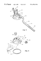
- FIG. 4 is an exploded view showing the elements of the lid including a coupling for attachment to the power unit connection and an inlet adapter for attachment to the inlet connection, and a removable filter and foam stripping for attachment to the underside of the lid.
- FIG. 5 is a top view of the lid showing the raised portion and the location of the power unit connection power unit connection and inlet connection.
- FIG. 6 is a bottom view of the lid showing the through holes and depression for placement of the removable filter.
- FIG. 7 is a perspective view of the transparent collapsible container of the collection apparatus showing the panels assembled together using hardware.
- FIG. 8 is a view of one of the disassembled, flat panels which form the container of the collection apparatus.
- FIG. 9 is a perspective view of the transparent collapsible container of the collection apparatus with interlocking panels assembled together to form a cylindrical container.
- FIG. 10 is an enlarged top view of the interlocking members of the panels forming the container.
- FIG. 11 is a perspective view of the transparent collapsible container of the collection apparatus showing the panels assembled together using a connector strip.
- FIG. 12 is an enlarged top view of a connector strip member to be attached to the panels for securing the panels together to form the container.
- FIG. 12A is an enlarged top view of the container showing the panel formed into the cylindrical container and secured with a C-shaped connector strip.
- FIG. 13 is a perspective view of a second filter to provide the collection apparatus with a double filtration feature.
- FIG. 14 is a side view of a base to accommodate the collapsible container, storage of spare bags and various attachments and shows a platform for placement of a gasoline or propane powered generator.
- FIG. 15 is a top view of the base illustrated in FIG. 14 .
- the collection apparatus or drum kit of the subject invention for use with blower/vacuum units for easily and quickly collecting and storing large amounts of bulky debris is generally designated by the numeral 20 .
- the collection apparatus 20 includes a large drum or container 22 having an open top 23 , a removable lid 24 , a disposable and reusable liner 26 and a base 28 for moveably supporting the container 22 .
- the collection apparatus 20 of the subject invention utilizes a blower/vacuum unit, such as vacuum unit 32 and a variety of intake hose attachments, such as intake hose attachment 34 , having a large diameter capacity to quickly and easily clean up large volumes of bulky debris while simultaneously depositing the debris into the container 22 .
- the removable lid 24 of the subject invention includes a top outer side 36 having a raised portion 38 and a bottom underside 40 having a depression 42 formed by the raised portion 38 .
- the lid 24 includes a rim 44 extending downward from the top outer side 36 around the perimeter of the lid 24 for securing the lid to the barrel or container 22 .
- the lid is molded of a lightweight, transparent, durable material, such as by way of example, a resilient plastic material and is sized to fit over the open top 23 of the container 22 .
- the top outer side 36 includes a first inlet or power unit connection 46 near the center of the raised portion 38 which is adapted to be attached to a blower/vacuum unit, such as vacuum unit 32 .
- the top outer side 36 also includes a second inlet or inlet connection 48 , separate from the power unit connection 46 , which is adapted for attaching a large diameter intake hose attachment, such as intake hose attachment 34 , to the lid 24 .
- the inlet connection 48 comprises a raised inlet port 50 which extends above the top outer side 36 of the lid 24 .
- FIG. 6 illustrates the bottom underside 40 of the lid 24 and shows the power unit connection and inlet connection 46 , 48 extending through the lid 24 and forming first and second through holes 52 , 54 in the bottom underside 40 of the lid 24 .
- the inclusion of the inlet connection 48 on the lid 24 permits the debris to be drawn directly into the container 22 without passing through the power unit connection 46 on which the vacuum unit is mounted. Thus, the debris bypasses the vacuum unit 32 and does not enter the impeller and is deposited directly into the container 22 .
- the raised inlet port 50 of the inlet connection 48 is designed to include an inlet adapter 56 which is universally adapted to fit different intake hose accessories having a variety of hose sizes for carrying debris into the container 22 .
- universal couplings or attachment components 58 may be included for quickly and easily securing a blower/vacuum unit to the power unit connection 46 and for quickly and easily securing a variety of intake hose attachments to the inlet connection 48 .
- the attachment component 58 is adapted to be received by the inlet adapter 56 and may be connected to one end of the intake hose attachment 34 for securely attaching the intake hose attachment 34 to the lid 24 .
- the attachment component 58 may be connected to the power unit connection 46 and is adapted to be attached to the vacuum unit 32 for mounting the vacuum unit to the lid 24 .
- the inlet adapter 56 of the preferred embodiment has a 4 inch diameter intake for large intake capacity and may be adapted to fit 2 1 ⁇ 2 inch diameter cleaning accessories.
- the collection apparatus 20 of the subject invention may also include an assortment of tools and hose arrangements for allowing a thorough means of vacuuming large industrial areas in a three dimensional fashion.
- the assortment of tools and hose arrangements may include clear extensions tubes and flexible hoses in 2 1 ⁇ 2 and 4 inch diameters and in different lengths, such as 5, 10 and 25 feet.
- a standard accessory kit may include a 2 1 ⁇ 2 inch to 4 inch adapter fitting, extension wands each 20 inches long, an elbow, an elbow dusting brush, a debris tool, a crevice tool, a heavy duty wall/floor tool (14 inches long) and a fabric took caddy.
- the intake hose attachment 34 may be a flexible hose 60 which is attached to an intake chute 62 having a handle 64 with a foam grip 66 .
- the intake chute 62 is attached to the flexible hose using a pair of couplings 68 , a swivel 70 and a collar 72 .
- the removable lid 24 includes an integral filter 25 which serves as an air-cleansing medium to contain small air borne dust and dirt particulates from discharging freely into the atmosphere.
- the integral filter 25 is located in the indented portion or depression 42 so that it is positioned between the power unit connection 46 and the interior of the container 22 for filtering air drawn through the first inlet by the blower/vacuum unit attached to the power unit connection 46 .
- the filter 25 is removably attached to the underside of the lid and includes a hook and loop type fastener 27 with complementary mated fastener strips 29 , such as with VELCRO (R), for easily and quickly removing the filter 25 and reattaching the same.
- the filter 25 can be cleaned simply by detaching it from the Velcro (R) strips 29 , without requiring the use of tools, and shaking it vigorously, using a compressed air hose or by rinsing it.
- the lid 24 of the preferred embodiment may also include a foam or rubber stripping 33 along the interior of the rim 44 for securing the lid to the container 22 (see FIG. 2 ).
- the foam stripping 33 provides an air seal between the lid and the container which increases air intake and cleaning efficiency at the collection point of the cleaning accessories.
- the subject invention utilizes a vacuum unit 32 which operates under low static pressure and high CFM, as shown in U.S. Pat. No. 5,722,110 incorporated by reference herein.
- the preferred vacuum unit 32 includes an impeller housing, an impeller disposed within the impeller housing, a motor housing attached to the impeller housing, a motor disposed within the motor housing and a discharge chute 74 .
- the vacuum unit includes a powerful one horsepower motor which creates 500 cubic feet of airflow, not any appreciable static pressure, and optional voltages of 100, 115, 230 are available for the vacuum unit.
- the vacuum unit is versatile and may be mounted on the removable lid 24 of the subject invention or can be easily transformed to a portable cleaner which is mounted as a shoulder or a backpack unit or can be easily mounted to a wheel base for mobility as shown in U.S. Pat. No. 5,722,110.
- a second collection bag 76 such as the universal collection bag shown therein and available with most state of the art vacuum/blowers, can be fitted to the discharge chute 74 to provide secondary filtration (see FIG. 13 ). While the preferred vacuum unit 32 is illustrated herein, it will be understood that a variety of electrically or fuel powered vacuum and blower units may be used in connection with the subject invention.
- a standard drum such as by way of example, a 55 gallon drum or another large receptacle or container having an open top
- the removable lid 24 may be custom molded to securely fit and cover the open top of the selected container.
- the container 22 is a collapsible, lightweight, transparent container comprised of one or more substantially flat sheets or panels 35 which may be readily assembled to form the container having a hollow interior 37 , open top 23 and open bottom 39 and may be readily disassembled to conveniently store and ship the container. Referring to FIGS.
- the collection apparatus 20 of the subject invention includes three embodiments of the preferred collapsible container 22 each having a different means for connecting the panels to one another to form the collapsible container 22 . While three embodiments are shown, it will be understood that the invention is directed to the use of multiple panels to form a collapsible, transparent, lightweight container for use with blower/vacuum units and any suitable means for connecting the panels together to form the collapsible container may be utilized.
- the panels 35 have opposite side ends 41 , 43 and are a sturdy, lightweight, semi-flexible or resilient plastic material. The preferred panels 35 are transparent for permitting the operator to easily monitor the remaining capacity of the collapsible container 22 while it is in use.
- the clear, plastic panels 35 comprising the container 22 are approximately 0.100 inches thick and approximately 28′′ ⁇ 34′′ so as to form a 24′′ internal diameter when joined and forming the cylindrical container 22 . While two panels 35 are illustrated, it will be understood that one or more panels may be utilized as desired to form the collapsible container 22 .
- the panels include top and bottom ends 100 , 102 each having a rim 104 and may include a top and bottom sponge or rubber type air seal member 106 adapted to be fitted onto the top and bottom rims of the cylindrical container (See FIG. 11 ).
- the panels 35 are assembled into the collapsible container 22 using hardware to secure the panels together to for the cylindrically shaped container 22 .
- the panel sides 41 , 43 include panel edges 45 , 47 with one panel side 41 having a double layer of material at the panel edge 45 to form a pocket for receiving the panel edge 47 of the adjacent panel 35 (see FIG. 8 ).
- the panel edges 45 , 47 are then secured to each other utilizing washers 49 , screws 51 , nuts 53 and/or push-through fasteners which penetrate the panel edges 45 , 47 and secure the panels 35 together to form the cylindrically shaped barrel or container 22 .
- FIG. 7 In the second embodiment shown in FIG.
- the panels 35 of the collapsible barrel are custom molded to interlock with one another using no hardware to form the cylindrical container 35 .
- the panel edges 45 , 47 of the second embodiment include a hook-shaped end for hooking onto the adjacent panel edge 45 or 47 and securing the panels 35 to form the cylindrically shaped container 22 .
- the panels 35 have flat edges 45 , 47 and are assembled into the collapsible barrel 22 by attaching a plastic or metal connector strip 55 between the panel edges 45 , 47 of two adjacent panels 35 (see FIG. 11 ). As shown in FIG.
- the connector strip 55 includes an “H” shaped member 57 having opposite sides 59 , 61 and a holder 63 extending from each side 59 , 61 of the member 57 having a slot 65 which is adapted to receive the panel edges 45 , 47 of two adjacent panels 35 .
- the panel edges 45 , 47 are approximately 1 ⁇ 8 inch thick and fit snugly within the slot 65 .
- Each holder 63 includes a taper in the slot 65 for securely holding the panel edges 45 , 47 therein.
- the container is constructed using a single panel having C-shaped end. The C-shaped ends engage a connector strip 108 having opposite ends 110 , 112 . As shown in FIG.
- the connector strip 108 fits over the C-shaped panel edges 45 , 47 to secure the panel in the shape of a cylindrical container. While the preferred container is a collapsible, multi-piece drum, it will be understood that most large containers may be used with the subject invention, including, but not limited to, a standard 55 gallon drum, a cardboard or plastic container and the like.
- the collapsible container 22 includes the transparent disposable bag or liner 26 having an open top end 15 , side walls 17 and a closed bottom end for receiving and storing the debris deposited into the container 22 .
- the preferred liner 26 includes a plurality of through or vent holes 21 near the open top end 15 to provide an air path through which air entering the container may escape for preventing the liner 26 from collapsing.
- the vent holes 21 are located in the top one third of the liner 26 while the bottom two-thirds of the bag is sealed for preventing leaking or spills as the bag is lifted and removed from the container 22 .
- the liner 26 is an internal plastic disposable bag which is utilized under the low static pressure and high CFM condition.
- the subject invention may also include a means for further securing the lid 24 to the container.
- the invention includes at least three strap ring assemblies 78 spaced along and secured to the rim 44 of the lid 24 and at least three bungee-type cords 80 having opposite ends 82 , 84 with one end 82 secured to the base 28 or the wall of the container and the other end 84 including a hook 86 (see FIGS. 1 - 2 ).
- the cords 80 extend upward from the base or wall of the container and the hook 86 is hooked to the strap rings 78 on the lid 24 for helping to secure the lid to the container 22 and prevent accidental removal of the lid 24 during use.
- the base 28 of the subject invention supports the bottom of the container 22 and includes a plurality of wheels 88 for easily maneuvering the container.
- the base 28 includes a closed bottom 90 and an upstanding sidewall 92 and is sized to fit and forms the bottom of the collapsible container 22 .
- the base 28 is sized to fit the bottom of the container and may be a round dolly, such as, by way of example, a RUBBERMAID 55 gallon drum dolly or the like, and is designed to snuggly contain the sectional, clear plastic barrel or container 22 of the preferred embodiment or a standard 55-gallon drum.
- the base may also be a rotational molded plastic component 93 or constructed of tubular and/or sheet metal and may employ a handle 94 for pushing the container and for ease of maneuverability. As shown in FIGS. 14 and 15, it may also be designed so as to included slots or holes or a storage bag 96 for storing spare bags and the various attachments when not in use and employ a platform 98 to accommodate a gasoline or propane powered generator.
Abstract
Description
Claims (40)
Priority Applications (3)
| Application Number | Priority Date | Filing Date | Title |
|---|---|---|---|
| US08/953,847 US6170118B1 (en) | 1997-10-15 | 1997-10-15 | Collection apparatus for use with blower/vacuum units |
| PCT/US1998/021756 WO1999019703A2 (en) | 1997-10-15 | 1998-10-15 | Collection apparatus for use with blower/vacuum units |
| GB0009274A GB2348357A (en) | 1997-10-15 | 1998-10-15 | Collection apparatus for use with blower/vacuum units |
Applications Claiming Priority (1)
| Application Number | Priority Date | Filing Date | Title |
|---|---|---|---|
| US08/953,847 US6170118B1 (en) | 1997-10-15 | 1997-10-15 | Collection apparatus for use with blower/vacuum units |
Publications (1)
| Publication Number | Publication Date |
|---|---|
| US6170118B1 true US6170118B1 (en) | 2001-01-09 |
Family
ID=25494609
Family Applications (1)
| Application Number | Title | Priority Date | Filing Date |
|---|---|---|---|
| US08/953,847 Expired - Lifetime US6170118B1 (en) | 1997-10-15 | 1997-10-15 | Collection apparatus for use with blower/vacuum units |
Country Status (3)
| Country | Link |
|---|---|
| US (1) | US6170118B1 (en) |
| GB (1) | GB2348357A (en) |
| WO (1) | WO1999019703A2 (en) |
Cited By (41)
| Publication number | Priority date | Publication date | Assignee | Title |
|---|---|---|---|---|
| US20030126697A1 (en) * | 2000-02-25 | 2003-07-10 | Mtd Products, Inc. | Adjustable vacuum nozzle |
| US20040197031A1 (en) * | 2003-04-07 | 2004-10-07 | Rhett Torick | Apertured leaf bag |
| US20050193701A1 (en) * | 2004-02-18 | 2005-09-08 | Schiller-Pfeiffer, Inc. | Apparatus for processing of organic material |
| US20050194062A1 (en) * | 2004-03-05 | 2005-09-08 | Anderson Keith A. | Collapsible apparatus for recovering and dispensing lightweight objects |
| US20060069224A1 (en) * | 2004-09-14 | 2006-03-30 | Wolfgang Pritschins | Copolymers, preparation thereof and use as wetting agents and dispersants |
| US7179062B1 (en) * | 2005-10-21 | 2007-02-20 | Drevitson Kyle C | Integrated shop vacuum and air compressor system |
| US20070089262A1 (en) * | 2005-10-21 | 2007-04-26 | Drevitson Kyle C | Integrated shop vacuum and air compressor system |
| US20070113528A1 (en) * | 2005-10-18 | 2007-05-24 | Knuth Steven L | Vacuum bag mounting and viewing features |
| US20070186371A1 (en) * | 2002-04-04 | 2007-08-16 | Moore Glen E | Cleaning assembly |
| WO2007109348A2 (en) * | 2006-03-21 | 2007-09-27 | Mcintyre Paul C | Gutter cleaning vacuum system including a novel hinged vacuum manifold assembly |
| US20080000045A1 (en) * | 2006-06-28 | 2008-01-03 | Kuo-Chin Cho | Vacuum dust-collecting barrel loaded on a movable loading frame |
| US20080295280A1 (en) * | 2007-06-01 | 2008-12-04 | Goodger William H | Bagger attachment for leaf blower |
| US20090271943A1 (en) * | 2008-04-24 | 2009-11-05 | Williamson Susan J | Portable cleaning assembly with waste container and anti tip-over protection |
| US20090308254A1 (en) * | 2006-07-18 | 2009-12-17 | Dyson Technology Limited | Handheld cleaning appliance |
| US20100058553A1 (en) * | 2003-07-10 | 2010-03-11 | Black & Decker Inc. | Utility Vacuum |
| US20100107579A1 (en) * | 2008-11-04 | 2010-05-06 | Meyer Gretchen A | Apparatus for collecting lightweight packing particulates |
| US20100122428A1 (en) * | 2008-10-14 | 2010-05-20 | Williamson Susan J | Portable cleaning assembly with vacuum unit disposed within cavity of waste container |
| US20100230920A1 (en) * | 2008-06-09 | 2010-09-16 | Thibault Richard R | Wheeled container platform for a single bucket |
| US20110000037A1 (en) * | 2009-07-01 | 2011-01-06 | Racine Industries, Inc. | Combination of Carpet-Cleaning Machine and Platform for Transporting the Machine |
| WO2011009197A1 (en) * | 2009-07-21 | 2011-01-27 | Northman Holdings Inc. | Collapsible wet/dry vacuum |
| US20110062091A1 (en) * | 2009-09-15 | 2011-03-17 | Exair Corporation | Liquid Vacuuming And Filtering Device And Method |
| US7962996B1 (en) | 2010-03-04 | 2011-06-21 | Jack Mondello | Mobile yard vacuum cart for use with hand-held leaf blowers |
| US7987548B1 (en) * | 2006-03-06 | 2011-08-02 | Hays John N | Leaf and lawn vacuum bagger |
| USD666369S1 (en) | 2010-11-12 | 2012-08-28 | Emerson Electric Co. | Combined wet/dry vacuum cleaner with integrated tool storage |
| US20130031740A1 (en) * | 2011-08-04 | 2013-02-07 | Laliberte William | Leaves collection system for use with a portable blower/vacuum and a lid allowing the rejection and the retention of debris in a bag |
| US8448570B1 (en) | 2012-10-19 | 2013-05-28 | John A. Turner | Portable electric can crusher |
| US20130180070A1 (en) * | 2012-01-12 | 2013-07-18 | William Laliberté | Lid with a curved edge for use with a leaves collection system with a portable blower/vacuum allowing the rejection and retention of debris in a bag |
| US20130333138A1 (en) * | 2012-06-15 | 2013-12-19 | William Laliberté | Lid with a curved edge and domed air outlets for the collection of leaves with a blower/vacuum and the rejection of debris into a bag |
| US20140075706A1 (en) * | 2012-09-17 | 2014-03-20 | William Laliberté | Lid with curved edge and domed air outlets and fastening method for the connecting pipe for collecting leaves with a blower/vacuum and the discharge of debris into a bag |
| US20140173848A1 (en) * | 2011-06-13 | 2014-06-26 | Jake Tyler | Vacuum cleaner comprising a dust - bag - housing made of paper |
| US20140283330A1 (en) * | 2013-03-21 | 2014-09-25 | Leo Tardif | Platform for attaching a portable vacuum unit on a container |
| US20140345078A1 (en) * | 2013-05-24 | 2014-11-27 | EVO Development, LLC | Thermoforming trim removal systems and methods |
| US8914939B1 (en) * | 2012-04-30 | 2014-12-23 | Steve Anthony Aragona | Vacuum cleaner |
| US20150040948A1 (en) * | 2013-08-07 | 2015-02-12 | Perry Sickler | Vacuum Plate and Vacuum System |
| US20150074936A1 (en) * | 2012-03-27 | 2015-03-19 | Black & Decker Inc. | Vacuum |
| US9004989B1 (en) * | 2013-11-27 | 2015-04-14 | Mark A. Ogier | Vacuum apparatus and product recovery method |
| US9668625B2 (en) * | 2015-09-10 | 2017-06-06 | Emerson Electric Co. | Vacuum having a metal drum and a polymer base |
| US20180078104A1 (en) * | 2016-09-19 | 2018-03-22 | Tti (Macao Commercial Offshore) Limited | Vacuum cleaner |
| US10377401B2 (en) | 2016-05-12 | 2019-08-13 | Richard Thibault | Interchangeable and modular carts |
| US10485172B2 (en) * | 2016-10-13 | 2019-11-26 | Terry Todd Cooper | Device and method of use for pecan picking |
| US20200397200A1 (en) * | 2018-03-02 | 2020-12-24 | Techtronic Floor Care Technology Limited | Vacuum cleaner |
Families Citing this family (3)
| Publication number | Priority date | Publication date | Assignee | Title |
|---|---|---|---|---|
| ITPI20090056A1 (en) * | 2009-05-08 | 2010-11-09 | Gartec S R L | CONTAINER STRUCTURE FOR LIQUIDS |
| WO2020121576A1 (en) * | 2018-12-12 | 2020-06-18 | 株式会社アルバック | Vacuum gauge and pressure measurement system comprising vacuum gauge |
| DE202019101989U1 (en) | 2019-04-05 | 2019-04-11 | Ralph Bischoff | Cleaning device for coffee machines and semi-automatic machines and the surrounding work surface |
Citations (28)
| Publication number | Priority date | Publication date | Assignee | Title |
|---|---|---|---|---|
| US1328458A (en) | 1917-08-10 | 1920-01-20 | Schiek Louis | Bucket |
| US3082465A (en) | 1961-03-06 | 1963-03-26 | Multi Clean Products Inc | Vacuum cleaning apparatus |
| US3193847A (en) | 1962-12-31 | 1965-07-13 | John J Mashura | Collapsible swimming pool |
| US3570222A (en) | 1969-05-13 | 1971-03-16 | Singer Co | Wet or dry shop vacuum cleaner |
| US3740933A (en) * | 1971-06-07 | 1973-06-26 | J Hollowell | Vacuum trash collector |
| US3957327A (en) | 1974-11-04 | 1976-05-18 | Parrish's Cake Decorating Supplies, Inc. | Protective cover for wedding cakes, or other display items |
| US4072483A (en) | 1976-05-20 | 1978-02-07 | Doyle Vacuum Cleaner Company | Vacuum cleaners |
| US4105420A (en) | 1977-05-23 | 1978-08-08 | Bayfront Carpet And Vacuum, Inc. | Canister vacuum cleaner with transparent lid |
| US4222753A (en) | 1978-06-02 | 1980-09-16 | Mills Robert G | Suction cleaner |
| US4467494A (en) | 1982-04-19 | 1984-08-28 | Jones Judson O | Industrial vacuum cleaner |
| US4569100A (en) | 1984-09-11 | 1986-02-11 | The Scott & Fetzer Company | Vacuum device |
| US4654926A (en) * | 1985-04-08 | 1987-04-07 | Central Quality Industries, Inc. | Vacuum cleaner |
| US4715872A (en) | 1986-09-19 | 1987-12-29 | Shopsmith, Inc. | Portable dust collector |
| US4799699A (en) | 1987-05-06 | 1989-01-24 | Shop-Vac Corporation | Dolly frame |
| US4888849A (en) | 1988-09-12 | 1989-12-26 | Emerson Electric Co. | Wheeled hand cart for wet/dry utility vacuum cleaner |
| US4894881A (en) | 1989-03-03 | 1990-01-23 | Hako Minuteman, Inc. | Wet/dry vacuum machine |
| US4993107A (en) | 1988-05-20 | 1991-02-19 | Dulevo S.P.A. | Filtering and collecting device of solid and powder refuse for industrial and civil suction apparatus |
| US5052570A (en) | 1989-07-31 | 1991-10-01 | Roderic Johansen | Composting bin apparatus with U-shaped connecting members |
| US5069696A (en) | 1990-11-28 | 1991-12-03 | Bruno Iii Anthony R | Shop vac having external exhaust filter |
| US5209367A (en) | 1989-05-03 | 1993-05-11 | Musscher Ronald F Van | Sleeve for a container |
| US5242588A (en) | 1991-09-26 | 1993-09-07 | Reese Ronald K | Filter unit assembly |
| US5259087A (en) | 1991-12-27 | 1993-11-09 | Loveless Michael L | Ash vacuum |
| US5404614A (en) * | 1994-01-06 | 1995-04-11 | Royal Appliance Mfg. Co. | Latch assembly for blower of wet/dry vacuum cleaner |
| US5455983A (en) | 1993-01-15 | 1995-10-10 | The Hoover Company | Wet/dry utility vacuum cleaner |
| US5515573A (en) * | 1994-04-08 | 1996-05-14 | Hmi Industries Inc. | Vacuum cleaner canister base connector |
| US5528794A (en) | 1994-09-09 | 1996-06-25 | Emerson Electric Co. | Utility vacuum cleaner tool caddy and wheel mount |
| US5564155A (en) | 1995-08-10 | 1996-10-15 | Monesson; Joel | Removable liner for canister-type vacuum cleaner |
| US5606769A (en) | 1994-10-31 | 1997-03-04 | Emerson Electric Co. | Wet/dry utility vacuum cleaner with detachable blower |
-
1997
- 1997-10-15 US US08/953,847 patent/US6170118B1/en not_active Expired - Lifetime
-
1998
- 1998-10-15 WO PCT/US1998/021756 patent/WO1999019703A2/en active Application Filing
- 1998-10-15 GB GB0009274A patent/GB2348357A/en not_active Withdrawn
Patent Citations (28)
| Publication number | Priority date | Publication date | Assignee | Title |
|---|---|---|---|---|
| US1328458A (en) | 1917-08-10 | 1920-01-20 | Schiek Louis | Bucket |
| US3082465A (en) | 1961-03-06 | 1963-03-26 | Multi Clean Products Inc | Vacuum cleaning apparatus |
| US3193847A (en) | 1962-12-31 | 1965-07-13 | John J Mashura | Collapsible swimming pool |
| US3570222A (en) | 1969-05-13 | 1971-03-16 | Singer Co | Wet or dry shop vacuum cleaner |
| US3740933A (en) * | 1971-06-07 | 1973-06-26 | J Hollowell | Vacuum trash collector |
| US3957327A (en) | 1974-11-04 | 1976-05-18 | Parrish's Cake Decorating Supplies, Inc. | Protective cover for wedding cakes, or other display items |
| US4072483A (en) | 1976-05-20 | 1978-02-07 | Doyle Vacuum Cleaner Company | Vacuum cleaners |
| US4105420A (en) | 1977-05-23 | 1978-08-08 | Bayfront Carpet And Vacuum, Inc. | Canister vacuum cleaner with transparent lid |
| US4222753A (en) | 1978-06-02 | 1980-09-16 | Mills Robert G | Suction cleaner |
| US4467494A (en) | 1982-04-19 | 1984-08-28 | Jones Judson O | Industrial vacuum cleaner |
| US4569100A (en) | 1984-09-11 | 1986-02-11 | The Scott & Fetzer Company | Vacuum device |
| US4654926A (en) * | 1985-04-08 | 1987-04-07 | Central Quality Industries, Inc. | Vacuum cleaner |
| US4715872A (en) | 1986-09-19 | 1987-12-29 | Shopsmith, Inc. | Portable dust collector |
| US4799699A (en) | 1987-05-06 | 1989-01-24 | Shop-Vac Corporation | Dolly frame |
| US4993107A (en) | 1988-05-20 | 1991-02-19 | Dulevo S.P.A. | Filtering and collecting device of solid and powder refuse for industrial and civil suction apparatus |
| US4888849A (en) | 1988-09-12 | 1989-12-26 | Emerson Electric Co. | Wheeled hand cart for wet/dry utility vacuum cleaner |
| US4894881A (en) | 1989-03-03 | 1990-01-23 | Hako Minuteman, Inc. | Wet/dry vacuum machine |
| US5209367A (en) | 1989-05-03 | 1993-05-11 | Musscher Ronald F Van | Sleeve for a container |
| US5052570A (en) | 1989-07-31 | 1991-10-01 | Roderic Johansen | Composting bin apparatus with U-shaped connecting members |
| US5069696A (en) | 1990-11-28 | 1991-12-03 | Bruno Iii Anthony R | Shop vac having external exhaust filter |
| US5242588A (en) | 1991-09-26 | 1993-09-07 | Reese Ronald K | Filter unit assembly |
| US5259087A (en) | 1991-12-27 | 1993-11-09 | Loveless Michael L | Ash vacuum |
| US5455983A (en) | 1993-01-15 | 1995-10-10 | The Hoover Company | Wet/dry utility vacuum cleaner |
| US5404614A (en) * | 1994-01-06 | 1995-04-11 | Royal Appliance Mfg. Co. | Latch assembly for blower of wet/dry vacuum cleaner |
| US5515573A (en) * | 1994-04-08 | 1996-05-14 | Hmi Industries Inc. | Vacuum cleaner canister base connector |
| US5528794A (en) | 1994-09-09 | 1996-06-25 | Emerson Electric Co. | Utility vacuum cleaner tool caddy and wheel mount |
| US5606769A (en) | 1994-10-31 | 1997-03-04 | Emerson Electric Co. | Wet/dry utility vacuum cleaner with detachable blower |
| US5564155A (en) | 1995-08-10 | 1996-10-15 | Monesson; Joel | Removable liner for canister-type vacuum cleaner |
Non-Patent Citations (1)
| Title |
|---|
| PCT International Search Report mailed Jun. 3, 1999 in PCT/US98/21756. |
Cited By (71)
| Publication number | Priority date | Publication date | Assignee | Title |
|---|---|---|---|---|
| US6782582B2 (en) * | 2000-02-25 | 2004-08-31 | Mtd Products Inc | Vacuum unit with hose attachment member |
| US20030126697A1 (en) * | 2000-02-25 | 2003-07-10 | Mtd Products, Inc. | Adjustable vacuum nozzle |
| US20070186371A1 (en) * | 2002-04-04 | 2007-08-16 | Moore Glen E | Cleaning assembly |
| US20090113664A1 (en) * | 2002-04-04 | 2009-05-07 | Moore Glen E | Portable cleaning assembly with waste container |
| US7472456B2 (en) * | 2002-04-04 | 2009-01-06 | Vacbarrell Llc | Portable cleaning assembly with waste container |
| US7979954B2 (en) | 2002-04-04 | 2011-07-19 | Vacbarrel, Llc | Portable cleaning assembly with waste container |
| US20040197031A1 (en) * | 2003-04-07 | 2004-10-07 | Rhett Torick | Apertured leaf bag |
| US20100058553A1 (en) * | 2003-07-10 | 2010-03-11 | Black & Decker Inc. | Utility Vacuum |
| US8250703B2 (en) * | 2003-07-10 | 2012-08-28 | Black & Decker Inc. | Utility vacuum |
| US20050193701A1 (en) * | 2004-02-18 | 2005-09-08 | Schiller-Pfeiffer, Inc. | Apparatus for processing of organic material |
| US20050194062A1 (en) * | 2004-03-05 | 2005-09-08 | Anderson Keith A. | Collapsible apparatus for recovering and dispensing lightweight objects |
| US6973944B2 (en) | 2004-03-05 | 2005-12-13 | Industrial Components Technology, Inc. | Collapsible apparatus for recovering and dispensing lightweight objects |
| US20060069224A1 (en) * | 2004-09-14 | 2006-03-30 | Wolfgang Pritschins | Copolymers, preparation thereof and use as wetting agents and dispersants |
| US20070113528A1 (en) * | 2005-10-18 | 2007-05-24 | Knuth Steven L | Vacuum bag mounting and viewing features |
| US7662200B2 (en) | 2005-10-18 | 2010-02-16 | Electrolux Home Care Products, Inc. | Vacuum bag mounting and viewing features |
| US20070119016A1 (en) * | 2005-10-21 | 2007-05-31 | Drevitson Kyle C | Integrated shop vacuum and air compressor system |
| US20070089262A1 (en) * | 2005-10-21 | 2007-04-26 | Drevitson Kyle C | Integrated shop vacuum and air compressor system |
| US7179062B1 (en) * | 2005-10-21 | 2007-02-20 | Drevitson Kyle C | Integrated shop vacuum and air compressor system |
| US7987548B1 (en) * | 2006-03-06 | 2011-08-02 | Hays John N | Leaf and lawn vacuum bagger |
| US7917992B2 (en) | 2006-03-21 | 2011-04-05 | Mcintyre Paul Curtis | Gutter cleaning vacuum system including a novel hinged vacuum manifold assembly |
| WO2007109348A2 (en) * | 2006-03-21 | 2007-09-27 | Mcintyre Paul C | Gutter cleaning vacuum system including a novel hinged vacuum manifold assembly |
| US20070226945A1 (en) * | 2006-03-21 | 2007-10-04 | Mcintyre Paul C | Gutter cleaning vacuum system including a novel hinged vacuum manifold assembly |
| WO2007109348A3 (en) * | 2006-03-21 | 2008-01-03 | Paul C Mcintyre | Gutter cleaning vacuum system including a novel hinged vacuum manifold assembly |
| US20080000045A1 (en) * | 2006-06-28 | 2008-01-03 | Kuo-Chin Cho | Vacuum dust-collecting barrel loaded on a movable loading frame |
| US20090308254A1 (en) * | 2006-07-18 | 2009-12-17 | Dyson Technology Limited | Handheld cleaning appliance |
| US7931716B2 (en) * | 2006-07-18 | 2011-04-26 | Dyson Technology Limited | Handheld cleaning appliance |
| US20080295280A1 (en) * | 2007-06-01 | 2008-12-04 | Goodger William H | Bagger attachment for leaf blower |
| US7752706B2 (en) * | 2007-06-01 | 2010-07-13 | Goodger William H | Bagger attachment for leaf blower |
| US20090271943A1 (en) * | 2008-04-24 | 2009-11-05 | Williamson Susan J | Portable cleaning assembly with waste container and anti tip-over protection |
| US20100230920A1 (en) * | 2008-06-09 | 2010-09-16 | Thibault Richard R | Wheeled container platform for a single bucket |
| US8376376B2 (en) * | 2008-06-09 | 2013-02-19 | Richard R. Thibault | Wheeled container platform for a single bucket |
| US20100122428A1 (en) * | 2008-10-14 | 2010-05-20 | Williamson Susan J | Portable cleaning assembly with vacuum unit disposed within cavity of waste container |
| US20100107579A1 (en) * | 2008-11-04 | 2010-05-06 | Meyer Gretchen A | Apparatus for collecting lightweight packing particulates |
| US7979957B2 (en) | 2008-11-04 | 2011-07-19 | Meyer Gretchen A | Apparatus for collecting lightweight packing particulates |
| US20110000037A1 (en) * | 2009-07-01 | 2011-01-06 | Racine Industries, Inc. | Combination of Carpet-Cleaning Machine and Platform for Transporting the Machine |
| US8607411B2 (en) | 2009-07-01 | 2013-12-17 | Racine Industries, Inc. | Combination of carpet-cleaning machine and platform for transporting the machine |
| WO2011009197A1 (en) * | 2009-07-21 | 2011-01-27 | Northman Holdings Inc. | Collapsible wet/dry vacuum |
| US8268179B2 (en) | 2009-09-15 | 2012-09-18 | Exair Corporation | Liquid vacuuming and filtering device and method |
| US8153001B2 (en) * | 2009-09-15 | 2012-04-10 | Exair Corporation | Liquid vacuuming and filtering device and method |
| US20110062091A1 (en) * | 2009-09-15 | 2011-03-17 | Exair Corporation | Liquid Vacuuming And Filtering Device And Method |
| US7962996B1 (en) | 2010-03-04 | 2011-06-21 | Jack Mondello | Mobile yard vacuum cart for use with hand-held leaf blowers |
| USD666369S1 (en) | 2010-11-12 | 2012-08-28 | Emerson Electric Co. | Combined wet/dry vacuum cleaner with integrated tool storage |
| US9060660B2 (en) * | 2011-06-13 | 2015-06-23 | Techtronic Floor Care Technology Limited | Vacuum cleaner comprising a dust-bag-housing made of paper |
| US20140173848A1 (en) * | 2011-06-13 | 2014-06-26 | Jake Tyler | Vacuum cleaner comprising a dust - bag - housing made of paper |
| US20130031740A1 (en) * | 2011-08-04 | 2013-02-07 | Laliberte William | Leaves collection system for use with a portable blower/vacuum and a lid allowing the rejection and the retention of debris in a bag |
| US8732892B2 (en) * | 2011-08-04 | 2014-05-27 | William Laliberté | Leaves collection system for use with a portable blower/vacuum and a lid allowing the rejection and the retention of debris in a bag |
| US20130180070A1 (en) * | 2012-01-12 | 2013-07-18 | William Laliberté | Lid with a curved edge for use with a leaves collection system with a portable blower/vacuum allowing the rejection and retention of debris in a bag |
| US8739360B2 (en) * | 2012-01-12 | 2014-06-03 | William Laliberté | Lid with a curved edge for use with a leaves collection system with a portable blower/vacuum allowing the rejection and retention of debris in a bag |
| US9408509B2 (en) * | 2012-03-27 | 2016-08-09 | Black & Decker Inc. | Vacuum |
| US20160331198A1 (en) * | 2012-03-27 | 2016-11-17 | Black & Decker Inc. | Vacuum |
| US20150074936A1 (en) * | 2012-03-27 | 2015-03-19 | Black & Decker Inc. | Vacuum |
| US9844309B2 (en) * | 2012-03-27 | 2017-12-19 | Black & Decker Inc. | Vacuum |
| US8914939B1 (en) * | 2012-04-30 | 2014-12-23 | Steve Anthony Aragona | Vacuum cleaner |
| US8769768B2 (en) * | 2012-06-15 | 2014-07-08 | William Laliberté | Lid with a curved edge and domed air outlets for the collection of leaves with a blower/vacuum and the rejection of debris into a bag |
| US20130333138A1 (en) * | 2012-06-15 | 2013-12-19 | William Laliberté | Lid with a curved edge and domed air outlets for the collection of leaves with a blower/vacuum and the rejection of debris into a bag |
| US20140075706A1 (en) * | 2012-09-17 | 2014-03-20 | William Laliberté | Lid with curved edge and domed air outlets and fastening method for the connecting pipe for collecting leaves with a blower/vacuum and the discharge of debris into a bag |
| US8966705B2 (en) * | 2012-09-17 | 2015-03-03 | William Laliberté | Lid for leaves collection with a blower/vacuum and the discharge of debris into a bag |
| US8448570B1 (en) | 2012-10-19 | 2013-05-28 | John A. Turner | Portable electric can crusher |
| US20140283330A1 (en) * | 2013-03-21 | 2014-09-25 | Leo Tardif | Platform for attaching a portable vacuum unit on a container |
| US20140345078A1 (en) * | 2013-05-24 | 2014-11-27 | EVO Development, LLC | Thermoforming trim removal systems and methods |
| US9457508B2 (en) * | 2013-05-24 | 2016-10-04 | EVO Development, LLC | Thermoforming trim removal systems and methods |
| US20150040948A1 (en) * | 2013-08-07 | 2015-02-12 | Perry Sickler | Vacuum Plate and Vacuum System |
| US10582819B2 (en) * | 2013-08-07 | 2020-03-10 | Perry Sickler | Vacuum plate and vacuum system |
| US9004989B1 (en) * | 2013-11-27 | 2015-04-14 | Mark A. Ogier | Vacuum apparatus and product recovery method |
| US9668625B2 (en) * | 2015-09-10 | 2017-06-06 | Emerson Electric Co. | Vacuum having a metal drum and a polymer base |
| US10052001B2 (en) | 2015-09-10 | 2018-08-21 | Emerson Electric Co. | Vacuum having a metal drum and a polymer base |
| US10377401B2 (en) | 2016-05-12 | 2019-08-13 | Richard Thibault | Interchangeable and modular carts |
| US10723375B2 (en) | 2016-05-12 | 2020-07-28 | Richard Thibault | Interchangeable and modular carts |
| US20180078104A1 (en) * | 2016-09-19 | 2018-03-22 | Tti (Macao Commercial Offshore) Limited | Vacuum cleaner |
| US10485172B2 (en) * | 2016-10-13 | 2019-11-26 | Terry Todd Cooper | Device and method of use for pecan picking |
| US20200397200A1 (en) * | 2018-03-02 | 2020-12-24 | Techtronic Floor Care Technology Limited | Vacuum cleaner |
Also Published As
| Publication number | Publication date |
|---|---|
| WO1999019703A2 (en) | 1999-04-22 |
| GB0009274D0 (en) | 2000-05-31 |
| WO1999019703A3 (en) | 1999-08-05 |
| GB2348357A (en) | 2000-10-04 |
Similar Documents
| Publication | Publication Date | Title |
|---|---|---|
| US6170118B1 (en) | Collection apparatus for use with blower/vacuum units | |
| US10555657B2 (en) | Floor treatment apparatus | |
| US6732403B2 (en) | Portable cleaning assembly | |
| US7917992B2 (en) | Gutter cleaning vacuum system including a novel hinged vacuum manifold assembly | |
| KR101230294B1 (en) | A domestic appliance | |
| US9510721B2 (en) | Floor cleaning apparatus | |
| US3310828A (en) | Vacuum cleaner | |
| US4845793A (en) | Dual vacuum cleaner | |
| US6122796A (en) | Suction cleaning apparatus | |
| CA2406265C (en) | Upright vacuum cleaner with cyclonic airflow pathway | |
| US5379483A (en) | Vacuum cleaner having a tool attached to the nozzle | |
| US20070163075A1 (en) | Stair cleaning vacuum cleaner | |
| US7210193B2 (en) | Portable cleaning assembly | |
| US6374453B1 (en) | Convertible vacuum cleaner | |
| US5337443A (en) | Vacuum cleaner | |
| US7272869B1 (en) | Ergonomic multi-functional cleaning machine | |
| US20090007367A1 (en) | Attachment device | |
| US20070209141A1 (en) | Vacuum attachment for a floor buffer | |
| US10863878B2 (en) | System and method for improved recirculating vacuum with removable nozzle | |
| US4961246A (en) | Vacuum cleaning device | |
| WO2007084543A2 (en) | Stair cleaning vacuum cleaner | |
| JPH0424010A (en) | Suction cleaner | |
| CA1189259A (en) | Cordless vacuum cleaner bowl and filter systems | |
| WO2011009197A1 (en) | Collapsible wet/dry vacuum | |
| AU2006200417A1 (en) | Bin attachment device |
Legal Events
| Date | Code | Title | Description |
|---|---|---|---|
| AS | Assignment |
Owner name: MCINTYRE, PAUL CURTIS, NORTH CAROLINA Free format text: ASSIGNMENT OF ASSIGNORS INTEREST;ASSIGNOR:ROBINSON, MICHAEL A.;REEL/FRAME:009552/0331 Effective date: 19981009 |
|
| FEPP | Fee payment procedure |
Free format text: PAYOR NUMBER ASSIGNED (ORIGINAL EVENT CODE: ASPN); ENTITY STATUS OF PATENT OWNER: SMALL ENTITY |
|
| REMI | Maintenance fee reminder mailed | ||
| FEPP | Fee payment procedure |
Free format text: PETITION RELATED TO MAINTENANCE FEES FILED (ORIGINAL EVENT CODE: PMFP); ENTITY STATUS OF PATENT OWNER: SMALL ENTITY |
|
| FEPP | Fee payment procedure |
Free format text: PETITION RELATED TO MAINTENANCE FEES GRANTED (ORIGINAL EVENT CODE: PMFG); ENTITY STATUS OF PATENT OWNER: SMALL ENTITY |
|
| REIN | Reinstatement after maintenance fee payment confirmed | ||
| FP | Lapsed due to failure to pay maintenance fee |
Effective date: 20050109 |
|
| FPAY | Fee payment |
Year of fee payment: 4 |
|
| PRDP | Patent reinstated due to the acceptance of a late maintenance fee |
Effective date: 20050927 |
|
| REMI | Maintenance fee reminder mailed | ||
| FEPP | Fee payment procedure |
Free format text: PETITION RELATED TO MAINTENANCE FEES FILED (ORIGINAL EVENT CODE: PMFP); ENTITY STATUS OF PATENT OWNER: SMALL ENTITY Free format text: PETITION RELATED TO MAINTENANCE FEES GRANTED (ORIGINAL EVENT CODE: PMFG); ENTITY STATUS OF PATENT OWNER: SMALL ENTITY |
|
| REIN | Reinstatement after maintenance fee payment confirmed | ||
| FP | Lapsed due to failure to pay maintenance fee |
Effective date: 20090109 |
|
| PRDP | Patent reinstated due to the acceptance of a late maintenance fee |
Effective date: 20090715 |
|
| FPAY | Fee payment |
Year of fee payment: 8 |
|
| STCF | Information on status: patent grant |
Free format text: PATENTED CASE |
|
| SULP | Surcharge for late payment | ||
| FPAY | Fee payment |
Year of fee payment: 12 |