US6183511B1 - Bileaflet heart valve having open channel and swivel pivots - Google Patents
Bileaflet heart valve having open channel and swivel pivots Download PDFInfo
- Publication number
- US6183511B1 US6183511B1 US09/165,442 US16544298A US6183511B1 US 6183511 B1 US6183511 B1 US 6183511B1 US 16544298 A US16544298 A US 16544298A US 6183511 B1 US6183511 B1 US 6183511B1
- Authority
- US
- United States
- Prior art keywords
- recess
- leaflet
- annular base
- leaflets
- plane
- Prior art date
- Legal status (The legal status is an assumption and is not a legal conclusion. Google has not performed a legal analysis and makes no representation as to the accuracy of the status listed.)
- Expired - Fee Related
Links
Images


Classifications
-
- A—HUMAN NECESSITIES
- A61—MEDICAL OR VETERINARY SCIENCE; HYGIENE
- A61F—FILTERS IMPLANTABLE INTO BLOOD VESSELS; PROSTHESES; DEVICES PROVIDING PATENCY TO, OR PREVENTING COLLAPSING OF, TUBULAR STRUCTURES OF THE BODY, e.g. STENTS; ORTHOPAEDIC, NURSING OR CONTRACEPTIVE DEVICES; FOMENTATION; TREATMENT OR PROTECTION OF EYES OR EARS; BANDAGES, DRESSINGS OR ABSORBENT PADS; FIRST-AID KITS
- A61F2/00—Filters implantable into blood vessels; Prostheses, i.e. artificial substitutes or replacements for parts of the body; Appliances for connecting them with the body; Devices providing patency to, or preventing collapsing of, tubular structures of the body, e.g. stents
- A61F2/02—Prostheses implantable into the body
- A61F2/24—Heart valves ; Vascular valves, e.g. venous valves; Heart implants, e.g. passive devices for improving the function of the native valve or the heart muscle; Transmyocardial revascularisation [TMR] devices; Valves implantable in the body
- A61F2/2403—Heart valves ; Vascular valves, e.g. venous valves; Heart implants, e.g. passive devices for improving the function of the native valve or the heart muscle; Transmyocardial revascularisation [TMR] devices; Valves implantable in the body with pivoting rigid closure members
Definitions
- the present invention relates generally to bileaflet hemodynamic heart valve prostheses of the type permitting translational and rotational movement of the leaflets, and particularly to a low-excursion prosthetic heart valve suitable for mitral valve replacement involving preservation of the papillary muscle and chordal structure wherein the valve may be oriented in either an anatomical or anti-anatomical configuration.
- the four combinations ranked by ascending level of risk include: (1) monoleaflet valve M with anterior orientation (FIG. 25 ); (2) bileaflet valve with anti-anatomical orientation (FIG. 26 ); (3) bileaflet valve with anatomical orientation (FIG. 27 ); and (4) monoleaflet valve M with posterior orientation (FIG. 28 ).
- the degree of risk associated with a bileaflet valve oriented in either the anatomical or anti-anatomical configuration depends upon the particular type of valve selected (particularly its range of excursions, radial exposure, and lateral exposure), the post-procedure anatomical characteristics of the annuls, and the patient's requirement for certain operational parameters associate with the valve.
- a physician may prefer to implant a bileaflet valve to obtain specific functional benefits associated with or unique to the particular bileaflet valve structure.
- the bileaflet valve has been extensively developed and refined. However, there is still room for further improvement. Problems associated with the weakening or structural failure of critical components in the valve are linked both to dynamic mechanical stresses and cavitation. It is noted that a certain amount of antegrade and retrograde leakage is generally anticipated. However, the amount of leakage is preferably maintained within acceptable limits corresponding roughly to normal anatomical valves. In addition, minimizing the physical size of the valve prosthesis, particularly the longitudinal dimensions of the annular base, produces greater excursion along the peripheral edges of the leaflets, while simultaneously increasing the difficulty in raising the heights of the pivot axis.
- U.S. Pat. No. 4,276,658 to Hanson provides a representative example of a conventional bileaflet heart valve. That valve utilizes a pair of semicircular pivot “ears” disposes on opposing sides of each leaflet received within “hourglass-shaped” slots to control the pivotal movement of the leaflets—including the angular sweep between the open and closed positions, the tiling of the valve away from its restrained pivotal axis, and the translational movement of the leaflet both parallel with its normal plane and along the linear flow path through the bore of the annular base.
- the Hanson '658 patent also describes the use of a pyrolytic carbon coating over a metallic or synthetic substrate for fabrication of the valve's components.
- U.S. Pat. No. 3,903,548 to Nakib discloses an effort to utilize the beneficial features of the monoleaflet principle in a bileaflet valve that similarly omits fixed pivotal axis, however the resulting cage structure produces an unacceptably small effective bore and correspondingly high pressure gradient across the valve.
- the leaflets may each pivot filly between the open and closed portions on the order of 80,000-120,000 times per day given a standard pulse of 60-80 beats per minute. Movement of the leaflets through a viscous aerated fluid such as blood may produce significant cavitation —the formation of partial vacuums caused by sudden movement of the flowing fluid away from the surface of the leaflets as a result of mechanical forces exerted by the leaflets. These partial vacuums produce “micro bubbles” on or near the surface of the leaflets, and when the pressure is released, vacuums change into positive pressure regions which lead to implosion of bubbles which can cause pitting of the surface of the leaflet.
- the cavitation potential is amplified greatly by the virtually instantaneous stopping and starting of the leaflets as they contact a rim along the annular base and also, in the case stopping, by the rate of speed at which the leaflet is traveling when it stops.
- Contact between the leaflet and the rim greatly increases the compressive forces on the adjacent fluid, and as the leaflet pivots away from the rim the corresponding effects of the expansions are magnified by increased negative pressures and stronger partial vacuums.
- standard cavitation produces pitting of metal surfaces due only to mechanical contact between the flowing fluid and moving object, introducing reciprocal movement and mechanical contact within the fluid cause the collapsing cavitation bubbles to strip or shear material from the leaflet surfaces at an accelerated rate. Although the surface pitting occurs at a near microscopic level, the result is surface degradation of the leaflet which can induce stress fractures and fragmentation leading to the premature failure of a leaflet.
- U.S. Pat. No. 4,078,268 to Possis discloses a substantially circular bore through the annular base, as well as a nearly complete separation between the peripheral edges of the leaflets and the annular base around the circumference of the valve. While this design obviates certain cavitation problems, it permits high levels of antegrade and retrograde leakage and places the entire load of restraining each leaflet on a pair of pivot pins received within adjustable bearing plugs. The combination of increased torque, absorbed impact forces, vibration, and normal frictional contact are believed to exert undue mechanical stresses on the relatively delicate pivot pins and bearing plugs.
- U.S. Pat. No. 5,080,669 to Tascon discloses an annular base that defines channels which intersect the pivot axis of the leaflets at various angles to direct flow of blood around enlargements in the leaflets that serve as the pivot axis, in an effort to cleanse the surfaces of the enlargements and prevent zones of thrombogenic stagnation from forming.
- the inward projections forming the channels and barriers restraining the leaflets in the Tascon '669 design create obstacles to uniform blood flow through the bore of the annular base, and define acute corners and crevices which can accelerate the formation of a thrombus.
- the enlargements continuously block a majority of the potential flow through each of the channels, thereby minimizing any cleansing effect that is realized.
- U.S. Pat. No. 4,892,540 to Vallana discloses a pair of vertical “chimneys” defined by the lobes of the annular base and communicating with the recesses in which the ears of the respective leaflets are received.
- blood flow in either the antegrade or retrograde direction passes between the pivot ears and the side wall of the annular base to cleanse the recess.
- the angled base portions forming each wedge-shaped separator body hold the pivot ears and leaflets in an elevated position proximate to the inlet from the chimney into the recess, thereby minimizing flow through the chimney.
- the pivot ears either reduce the flow rate within the recess or divert the flow away from portions of the recess where stagnation could occur, thus diminishing the effectiveness of any cleansing action.
- Tascon '669 contemplates alternating between multiple flow paths oriented at diverse angles to enhance the “scrubbing” effect
- Vallana '540 only contemplates cleansing that is substantially repetitive and reciprocal along one path for both antegrade and retrograde flow.
- Vallana '540 would produce an acceptable retrograde cleansing action due to the pressure differential created within the recess feeding into the chimney, it is at the expense of a significantly restricted non-circular bore through the annular base accounting for a substantial reduction in antegrade circulation.
- fibrin strands may be responsible for the formation of the fibrin strands, including regions of blood stagnation which provide a nidus for thrombogenic formations, or defects in the materials or structure of the valve that permit the direct attachment of blood cells. It may therefore readily be appreciated that two important goals when designing a bileaflet heart valve are maintaining optimal antegrade and retrograde circulation, and eliminating regions of reduced circulation within the valve that might foster the development of a thrombogenic mass.
- the Hanson '658 patent shows a relatively shallow semi-circular recess
- a bileaflet valve having pivot ears with a suitably shallow recess to enhance cleansing of the recess by normal antegrade and retrograde circulation.
- the commercially available embodiments of the Hanson '658 valve have recesses forming entrance angles ranging from 35° to 48° measured between the lateral wall of the bore and the tangentially adjoining surface of the recess, depending upon overall size of the valve.
- U.S. Pat. Nos. 5,246,453 to Bokros and 5,002,567 to Bona disclose alternate configurations in which the leaflets are not generally planar, and are supported by and pivot about fulcrums disposed on the lower portion of each leaflet. While these designs present an incursion both above and below the annular base, it allows the height of the annular base to be reduced somewhat relative to comparable bileaflet valves. While such a design is considered to be more responsive to reversal in the antegrade flow, it also relies upon shifting the axis of rotation relative to the leaflet's moment of inertia and therefore produces different operational characteristics than might normally be expected.
- leaflets must move through an arcuate path in response to fluid pressure applied from both the antegrade and retrograde directions, starting from differential initial orientations relative to the fluid pressure, and within an initially static versus initially dynamic environment. Consequently, valves having superior opening characteristics may be slow to close or resist complete closure, and vice versa.
- Leaflets having an angled, curved, or bicurved design to enhance the immediate responsiveness to changes in hemodynamic forces can be employed to address this problem.
- Another approach mentioned above is to increase the translational movement of the leaflet within the annular body, thereby permitting the leaflet to pivot more naturally about its inertial axis in direct response to the hemodynamic forces.
- This approach can potentially be more beneficial than merely moving the fixed axis of rotation nearer to the moment of inertia, since it also serves to reduce frictional forces and other physical impediments to proper valve operation.
- One limitation is the need to maintain proper alignment and seating of the leaflet without encumbering the flow passage with obstructions or incorporating free structures that increase the likelihood of valve failure.
- U.S. Pat. No. 4,535,484 to Marconi describes a bileaflet valve in which the leaflets are “free-floating”, thereby increasing translational movement and reducing the mechanical stresses imposed at localized pivot points and other load bearing surfaces.
- the Marconi '484 design requires a complex and fragile cage structure to restrain the leaflets, thereby producing a significant risk of damage to the valve during manufacturing or handling and increasing the potential for catastrophic failure of a valve component that would result in death or severe injury to the patient, mitigating against the use of certain materials such as pyrolytic carbon, and greatly increasing the cost and complexity of fabrication.
- U.S. Pat. No. 4,689,046 to Bokros describes a trapezoidal pivot ear having beveled edges, ideally decreasing the translational freedom, but enhancing the “sweeping” effect of the pivot ear to prevent thrombogenic formations within the recesses and distributing lateral stresses over a wider surface area.
- the faster blood flow in the center, relative to the sides, can cause additional turbulence within or downstream of the valve, or produce a pressure differential or venturi effect within the valve that can impede or retard the optimal translational or pivotal movement of the leaflets.
- the Possis '268 valve presents a larger central passage with narrower cross-sectional passages on each side, thereby reversing the fluid dynamics compared with the Hanson '658 design.
- the bileaflet heart valve prosthesis of the present invention comprises an annular base defining a substantially circular bore, and a pair of pivoting leaflets; each of the respective leaflets having first and second sides, the first side being a top side and the second side being a bottom side, the bottom sides of the respective leaflets generally facing one another when the respective leaflets are in an open position; each bottom side having an upper half and a lower half, a major portion of the upper half providing an upper surface lying generally in a first plane and a lower half providing a lower surface lying generally in a second plane, the first plane lying at an angle to the second plane; a third plane passing through a horizontal cross-section of the annular base, the first and second planes lying at angles to the third plane when the leaflets are in either the open or closed positions; wherein the first plane of each of the respective leaflets extends beyond an angle of 90° with respect to the third plane when the leaflets go from the fully closed position to the fully open position.
- the first plane can extend beyond a 90° angle with respect to the third plane when the leaflets go from the fully closed position to the fully open position without diminishing the leverage for closure of the leaflets when the leaflets are in the fully open position. This is because the lower portion of the bottom side of the leaflets remain at a suitable angle to allow for adequate leverage against the lower portion of the leaflet, to shift the leaflets within the respective recesses and pivot the leaflets to the closed position once the upper fulcrum edge comes into contact with the upper sidewall of the respective recess.
- each leaflet has a beveled bottom side which minimizes the travel angle “k′” between the open and closed positions.
- the lateral ends of each leaflet are received within “open channel” recesses where the ends are “free floating”, permitting translational and rotational movement of the leaflets within the respective recesses.
- each recess communicates with at least one groove extending around an inner peripheral surface of the annular base, and a cleansing flow is directed vertically or angularly through the recess to the groove during antegrade circulation, and from the grooves through the recess during retrograde flow and valve closure.
- the direction of this cleansing flow through the recesses varies depending upon the direction of circulation and the orientation of the leaflets, and is mostly unobstructed within the recesses by the leaflets.
- the peripheral edges of the leaflets present minimal incursion or exposure beneath the bottom of the annular base when the valve is completely open.
- the peripheral edge of each leaflet in the central region is preferably slightly spaced apart from the annular base to allow free movement of the leaflet and to avoid unsuccessful wear and/or stress.
- the peripheral edge of each leaflet in preferred embodiments only contacts the annular base adjacent the groove proximate the lateral regions of the leaflet.
- the angle at which fluid washing the surfaces of the annular base flows into the recesses is less than 35° to permit better washing dynamics.
- the preferred valve also has a dynamic pivot constructed primarily on the lateral sides of the leaflets where two fulcrum edges are created by notches in the peripheral edge. The leaflets pivot on each of the respective fulcrum edges at different points in the opening and closing cycle of the valve. This swivel pivot mechanism also permits significant translational movement of the leaflets especially in the fully open position. This mechanism is believed to provide a pivot mechanism which permits the valve to open and close more rapidly than prior art bileaflet valves.
- FIG. 1 is a perspective view of a preferred embodiment of the present invention showing the leaflets in a fully open position
- FIG. 2 is a lateral side view of the preferred bileaflet heart valve of the present invention shown in FIG. 1;
- FIG. 3 is a lateral side view of the preferred bileaflet heart valve shown in FIG. 1;
- FIG. 4 is a top plan view of the preferred bileaflet heart valve shown in FIG. 1;
- FIG. 5 is a bottom plan view of the preferred bileaflet heart valve shown in FIG. 1;
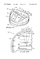
- FIG. 6 is a partially broken away elevated perspective view of the annular base of the preferred bileaflet heart valve shown in FIG. 1;
- FIG. 7 is a cross-sectional side view of the lateral side of the annular base of the preferred bileaflet heart valve shown in FIG. 1;
- FIG. 8 is a cross-sectional side view of the traverse side of the annular base of the preferred bileaflet heart valve shown in FIG. 1;
- FIG. 9A is an elevated perspective view of the bottom side of the preferred leaflet shown in FIG. 1;
- FIG. 9B is a cross-sectional perspective view of the preferred leaflet shown in FIG. 1, in a manner similar to that shown in FIG. 9A, but providing a perspective view only of a cross-section of the leaflet as seen from the line 9 B- 9 B of FIG. 9A;
- FIG. 10 is a bottom plan view of a leaflet of the preferred bileaflet heart valve shown in FIG. 1;
- FIG. 11 is a top plan view of a leaflet of the preferred bileaflet heart valve shown in FIG. 1;
- FIG. 12 is a vertical side view of a first lateral side of the leaflet of the preferred bileaflet heart valve shown in FIG. 1;
- FIG. 13 is a vertical side view of a second lateral side of the leaflet of the preferred bileaflet heart valve shown in FIG. 1;
- FIG. 14 is a horizontal side view of an upper edge, including the mating edge, of a leaflet of the preferred bileaflet heart valve shown in FIG. 1;
- FIG. 15 is a horizontal side view of the peripheral edge of the leaflet of the preferred bileaflet heart valve shown in FIG. 1;
- FIG. 16 is a diagrammatic cross-sectional view of the preferred bileaflet heart valve shown in FIG. 1 with the leaflets in a fully open position;
- FIG. 17 is a diagrammatic cross-sectional view of the preferred bileaflet heart valve shown in FIG. 1 illustrating the transition of the leaflets from a fully open position to a fully closed position;
- FIG. 18 is a partially broken away cross-sectional view of the recess as seen from the line 18 — 18 of FIG. 7;
- FIG. 19 is a partially broken away cross-sectional view of the recess as seen from the line 19 — 19 of FIG. 7;
- FIG. 20 is a partially broken away cross-sectional view of the recess similar to that shown in FIG. 19 but generally showing a lateral side portion of a leaflet within the recess when the leaflet is in a fully closed position as shown diagrammatically in FIG. 17 ;
- FIG. 21 is a partially broken away cross-sectional view similar to FIG. 20, but showing the leaflet in an open position as shown in FIG. 1;
- FIG. 22 is an elevated perspective view of the preferred bileaflet heart valve of the present invention similar to that shown in FIG. 1, except that the leaflets are in a fully closed position;
- FIG. 23 is a partially broken away bottom plan view of the preferred bileaflet heart valve shown in FIG. 22 when the leaflets are in a fully closed position;
- FIG. 24 provides a graphic representation of the quantity of blood flowing through a bileaflet heart valve during a single heart contraction cycle wherein the positive quantity indicates blood flowing in an antegrade direction and the negative quantity below the “y” axis indicates the quantity of blood flowing in the retrograde direction;
- FIG. 25 is a perspective view of a monoleaflet heart valve with anterior orientation as known to the prior art
- FIG. 26 is a perspective view of a bileaflet heart valve with anti-anatomical orientation
- FIG. 27 is a perspective view of a bileaflet heart valve with anatomical orientation
- FIG. 28 is a perspective view of a monoleaflet heart valve with posterior orientation as known to the prior art.
- FIG. 29 is a perspective view of a bileaflet heart valve of the present invention implanted in an anatomical orientation.
- the bileaflet heart valve prosthesis 110 of the present invention is preferably fabricated from a metal such a titanium, a carbon compound (or carbon with a minor percentage of silicon) such as pyrolytic carbon or the like, a metal alloy, or a suitable substrate coated with pyrolytic carbon as are well known in the art.
- a metal such as titanium, a carbon compound (or carbon with a minor percentage of silicon) such as pyrolytic carbon or the like, a metal alloy, or a suitable substrate coated with pyrolytic carbon as are well known in the art.
- a bileaflet heart valve 10 similar to the preferred heart valve prosthesis 110 of the present invention is shown diagrammatically implanted within the heart 101 of a patient, with the valve 10 sutured in place proximate to the mitral annulus 103 of the anatomical coronary valve and disposed above the papillary muscle and tendineae chordae 105 fixed to the posterior mitral annulus as described previously.
- the bileaflet valve 10 may be implanted in either the fully anatomical orientation or the fully anti-anatomical orientation as shown in FIGS.
- the preferred bileaflet heart valve 110 of the present invention shown in FIG. 1 includes an annular base 112 and first and second leaflets 114 .
- the fist and second leaflets 114 are mounted within the annular base 112 for pivotal movement between a fully open position, shown in FIGS. 1-5 and diagrammatically in FIG. 16, and in phantom in FIG. 17, and in a fully closed position shown in FIGS. 22-23 and diagrammatically in FIG. 17 .
- the annular base 112 has a top surface 124 and an inner wall 126 which defines a generally circular bore 116 passing through the annular base 112 in a direction generally parallel with a longitudinal axis 128 oriented generally in parallel with a vertical path for circulation of fluid or blood through the generally circular bore 116 .
- the top surface 124 of the annular base 112 is raised proximate opposing lateral sides 129 .
- the flat portions 130 of the lateral surfaces 133 include a pair of recesses 132 in each of the respective lateral sides 129 of the base 112 .
- Further lateral depressions 135 are centrally located in a lower portion of the inner surface 126 proximate each of the two lateral sides 129 , below and between the respective recesses 132 on each side, in the respective flat portions.
- these depressions have a curvilinear surface which would define a portion of one side of a cone.
- the recesses 132 extend into the respective flat portions 130 of the lateral surfaces 133 , thereby displacing a cylindrical bottom surface 140 of the recess 132 from the respective lateral surface 133 proximate the respective lateral side 129 .
- each of the cylindrical bottom surfaces 140 of the respective recesses 132 pass through a cylindrical radius which is “feathered out” as the cylindrical surface 140 approaches a junction with the respective lateral surface 133 .
- a line 181 shown in FIG. 19, which is tangential with a point on the cylindrical bottom surface 140 of the recess 132 just prior to a further point at which the cylindrical surface 140 is “feathered out” to form a junction with the lateral surface 133 , lies at an angle “g′” to a tangent line 184 which intersects line 181 and is tangential to the lateral surface 133 .
- a number of lines similar to line 181 which are tangential to a point on the cylindrical surface 140 must be considered. This may be an infinite number of lines.
- the entrance angle, “g′”, will be the angle between the lines 184 and 181 which will be the greatest angle that exists between the line 184 and any of the lines which can be drawn which intersect with line 184 and are tangential to a point on the cylindrical surface 140 .
- This angle “g′”, is representative of a recess entrance angle to the cylindrical recess 132 .
- the recess entrance angle is less than about 35°.
- the recess entrance angle “g′” is between about 20° and about 35°. More preferably, the recess entrance angle “g′” is from about 25° to about 34°. In even more preferred embodiments, the recess entrance angle “g′” ranges from about 28° to about 33.5°.
- the leaflets 114 have two sides, a top planar surface 142 and a beveled bottom side 143 .
- the bottom surface 143 has a peripheral bevel portion 144 proximate the peripheral edge 150 and a central portion or central bevel 145 proximate a mating edge 148 .
- the mating edge 148 has a narrow planar surface running nearly the entire width of the leaflet 114 .
- the respective leaflets are mirror images of one another in preferred embodiments so that when the respective leaflets 114 pivot to reside in the fully closed position, the mating edges 148 of the respective leaflets mate together to significantly obstruct blood flow through the very limited space between the respective mating surfaces 148 .
- the central beveled portion 145 of the beveled bottom side includes a flat planar surface 146 which is flanked on either side along the width W of the leaflets 114 , by curvilinear side surfaces 147 a and 147 b which rise up proximate lateral sides 151 of the leaflets 114 to flat side bevels 147 c and 147 d which separate the mating edges 148 from the peripheral bevel 144 on the beveled bottom side 143 proximate the respective lateral sides 151 .
- the width Wps of the flat planar surface 146 is greater than one-half of the width W of the leaflet 114 , and is therefore a major portion of the central bevel 145 .
- the phrase “a major portion” means a portion of the whole which has a width dimension which is at least as great as that of one-half of the width of the whole.
- the respective lateral sides 151 of the respective leaflets 114 each have a cylindrical surface proximate the diamond-shaped cylindrical surface 154 .
- Notches 153 , 155 are located adjacent to the diamond-shaped cylindrical surface 154 .
- the inflow notches 153 are located generally between the diamond-shaped cylindrical surface 154 and the top edge of the leaflet 114 .
- the generally V-shaped notch 153 is created and defined by an inflow flat 160 and an inflow side wall 156 of the diamond-shaped cylindrical surface 154 .
- the generally V-shaped notch 155 called the outflow notch 155 , is created and defined by an outflow flat 162 and an outflow side wall 158 of the diamond surface 154 .
- the present bileaflet heart valve 110 is designed with this in mind. All of the surfaces of the present valve 110 are actively washed at one time or another in the pumping cycle of the heart in which the valve 110 is implanted. When the valve 110 is in the fully opened position all of the surfaces of the side wall 126 are actively washed by blood flowing over the surfaces, as are the recesses 132 . The leaflets 114 are also actively washed as the blood flows in the antegrade direction through the bore 116 .
- the diamond-shaped cylindrical surface 154 also has a cylindrical radius generally consistent with the cylindrical radius of the bottom surface 140 of the recess 132 .
- the regurgitation is desirable to a certain degree, so long as the energy efficiency of the pumping activity of the heart is not compromised. The regurgitation occurs in a number of areas.
- retrograde blood flow may pass between the mating surfaces 148 of the respective leaflets 114 as demonstrated by arrows 194 , 195 and 196 in FIG. 22 .
- the bottom of the leaflets 114 also channel retrograde blood flow into the recesses 132 by directing the blood against the seats 136 created by the separation between the cylindrical bottom surface 140 and the upper edge 134 of the recesses 132 .
- An outflow side wall 158 of the diamond surface 154 may also channel retrograde blood flow to the recesses 132 and particularly to the seat 136 . This flow will then regurgitate between the leaflet 114 and the side wall 126 after it flows over the seat 136 and come out proximate the regurgitation representation arrows 191 , 192 and 193 .
- An axis 165 parallel with respective cylindrical surfaces on diamond-shaped cylindrical surfaces 154 of the respective leaflets 114 , and perpendicular the top surface 142 will lie at an angle “k” to an axis 167 , parallel with the respective cylindrical bottom surface 140 of respective recess 132 , and perpendicular with the upper edge 134 of the recess 132 , when the leaflets 114 are in the fully opened position.
- these respective axes 165 and 167 will be either superimposed upon one another, or in parallel with one another and the angle “k” will generally be about zero.
- the cylindrical surfaces 140 will be “matched” or “parallel” with the diamond-shaped surfaces 154 of the respective lateral sides 151 of the respective leaflets 114 .
- the angle “k”, shown diagrammatically in FIG. 17, is equal to the travel angle “k′”, when the leaflets 114 are in the fully open position.
- the leaflet 114 When the top side fulcrum edge 166 engages the seat 136 within the recess 132 , the leaflet 114 has already overcome any inertia it may have had when “resting” in the fully opened position. The translational movement will subsequently give way to pivotal movement of the leaflet toward the fully closed position. This pivotal movement will occur rapidly since the initial translational movement will provide some momentum which will be translated into pivotal or annular movement toward closure of the leaflets 114 .
- the initial movement of the leaflet is more likely to be followed immediately by a pivotal movement, because the cylindrical diamond-shaped surface 154 and the cylindrical recess bottom surface 140 are more closely mated as shown in FIG. 20 and the separation allowing translational movement from end to end is more limited.
- the leaflet 114 is likely to slip quickly from the upper side edge 134 toward the lower side sidewall 138 of the leaflet 114 .
- the leaflet will only begin to pivot after the bottom side fulcrum edge 164 is engaged with the lower side sidewall 138 . It will be appreciated, however, that the mechanism employed by the respective leaflets for pivoting is still a matter of inquiry and is not fully understood at this time.
- this dynamic pivot mechanism allows for faster opening and closing of the respective valves 110 .
- the leaflet 114 begins its linear motion immediately with the change in the flow direction and the linear momentum is transferred into angular momentum as soon as the top side fulcrum edge or pivot 166 contacts the seat 136 proximate the upper edge 134 of the recess 132 . This is believed to result in quicker closing than is exhibited by prior art devices.
- the preferred bileaflet heart valve prosthesis 110 of the present invention provides for a lowered thrombus potential due to the consideration given to access for washing in both the antegrade and retrograde directions.
- the dynamic pivot mechanism of the preferred leaflets 114 in cooperation with the preferred recesses 132 are believed to provide for faster opening and closing of the valve and less friction in the pivot area due to the use of a “rolling” pivot mechanism wherein the pivot activity changes focus from the top side fulcrum edge 166 to the bottom side fulcrum edge 164 .
- the preferred valve 110 also provides for a minimized travel angle “k′” between the fully opened position and the fully closed position.
- the travel angle provided in the preferred valve 110 may represent at least about 15-10° reduction in the travel angle as compared to many of the prior art devices. This reduction in the travel angle is believed to minimize angular velocity, wear, cavitation potential, and regurgitation volume, while increasing overall efficiency.
- the upper edges 134 for the preferred leaflets 114 are believed to slow the leaflet 114 just before closure due to the presence of significant amounts of fluids which may be “squeezed” or compressed against the sidewall 126 of the annular base 112 . Because the seats slow the leaflet 114 just before closure, they are believed to have a minimizing effect on the cavitation potential. It is also believed that the use of discontinuous seats, or seats which diminish prior to continuing into a seat extending from an opposite recess allows for a slight increase in regurgitation potential proximate the center portion of the leaflet where cavitation potential is generally highest due to the likelihood that this area is likely to be subjected to a greater angular velocity as it comes toward closure against the sidewall 126 .
- the seats 134 also decrease leakage or regurgitation proximate the lateral sides 129 of the annular base 112 when the leaflets 114 are in the closed position.
- the seats 134 are also believed to provide for increased antegrade flow to wash the flow channels or recesses 132 as the leaflets 114 close. As the leaflets 114 close the fluid in the recesses 132 begins to be “squeezed” or compressed within an upper portion of the recess distal to the transverse sides 131 of the annular base 112 .
- the width of the seats 134 decreases as they extend from the recess 132 to the transverse side 131 .
- the fluid “squeezed” or compressed against the seats 134 is generally believed to be released through the bore 116 after it washes at least a portion of the seat 134 . While the leaflets 114 are in the closed position, the seats 134 serve to reduce retrograde leakage or regurgitation and at least a portion of the retrograde flow is channeled around the diamond surface 154 , so as to thoroughly wash these areas when the leaflets 114 are in a closed position.
- the bottom surface of the recess 132 is in the form of a curvilinear cylindrical surface and is considered to have a generally cylindrical shape.
- cylindrical surface or cylindrical shape means a surface formed by linear translation of a curve, or a surface which has a radius similar to a portion of a surface of a cylinder.
- the diamond surface 154 at the lateral sides 151 of the leaflets 114 have a cylindrical shape which is “consistent” with or “mates” with the cylindrical recess bottom surfaces 140 of the recesses 132 . However, as shown in FIG. 20, the diamond surface 154 is consistent with and mates with the bottom surface 140 of the recess 132 only when the leaflet 114 is in the closed position.
- the flat planar surface 146 of the central bevel 145 and the peripheral bevel 144 of the bottom surface of the leaflet each lie generally in a plane respectively designated by tangent lines 172 and 174 .
- the peripheral bevel 144 and the flat planar surface 146 of the central bevel 145 lie generally in planes which lie at an angle to one another. In preferred embodiments this angle will be less than 180°, or preferably at an angle of about 161° to about 178°, more preferably about 166° to about 173°. In preferred embodiments, the angle “a” will be about 167° to about 172°.
- the angle “a” is about 169°.
- This bevel in the bottom surfaces of the leaflet 114 allows the angle of incidence for a flow of blood in the retrograde direction parallel with the longitudinal axis 128 to be a greater angle of incidence in respect to the peripheral bevel 144 than with the flat planar surface 146 of the central bevel 145 . This is believed to be advantageous for at least two reasons. First, since there is a greater angle of incidence, the force of the blood flowing in the retrograde direction will have greater impact upon the leaflet 114 and cause it to pivot toward the fully closed position more rapidly than might otherwise be expected.
- the difference between the respective bevels, and the angle of the tangent line 176 to the top planar surface 142 allow the peripheral edge 150 to have a shorter radial closing distance to travel before the leaflet 114 is in the fully closed position than might be expected for a leaflet having parallel surfaces.
- the angle of the plane in which the flat planar surface 146 of the central bevel 145 rests, to a horizontal plane 170 , which angle is consistent with the angle between tangent line 172 and the plane 170 , will be an angle “a′”.
- “a′” may range from about 84° to about 97°, preferably about 86° to about 95°, more preferably about 88° to about 94°, more preferably about 90° to about 92°, more preferably more than 90°, and in the most preferred embodiments, “a′” will be either 91°, or 91° or more.
- the angle between the plane in which the peripheral bevel 144 rests, and the horizontal plane 170 may be measured by taking the angle “b′” between the tangent line 174 and the horizontal plane 170 .
- the angle “b′” will be less than 87°, preferably less than 86°.
- “b′” will range from about 78° to about 84°, preferably about 80° to about 82°, and most preferably, it will be about 81°.
- the angle of the plane in which the top planar surface 142 of the top side of the leaflet 114 rests will lie at an angle “c′” to the horizontal plane 170 as measured between the tangent line 176 and the horizontal plane 170 when the leaflet is in the fully open position.
- “c′” is greater than about 78° and less than 90°, and preferably in a range of from about 82° to about 89°, preferably about 84° to about 88°. In the most preferred embodiment, “c′” is about 86°.
- the preferred embodiment of the bileaflet heart valve prosthesis 110 of the present invention will not have any sharp edges and that all edges will in fact be polished, smoothed or feathered so as to minimize shearing of blood as it passes over any of these edges.
- These smooth “transitions” between surfaces of all kinds will be obtained by shaving and polishing all edges so that the edges are rounded and have a smooth transition from one plane to another. Any radial surfaces of course will be polished as well.
- FIG. 24 generally provides a representation of the quantity (Q) of blood flowing through a bileaflet heart valve during a contraction cycle when the valve is in the aortic position. During systole, the quantity of blood passing through the valve in the antegrade direction (+) is fairly significant.
- the retrograde leakage (Ql) has been discussed herein and is believed to have a positive effect in respect to washing the various surfaces of the prosthetic heart valve, in that this “regurgitation” will “wash” the surfaces to reduce stagnation of blood as a measure against potential thrombus.
- the upper edge 134 blends or “feathers” into the inner wall 126 of the annular base 112 , as does the seat 136 , in preferred embodiments. It is believed that this has a very positive effect upon preservation of the integrity of the top planar surface 142 of the respective leaflets 114 by reducing cavitation potential. This is particularly true in an area approximately 15° to either side of a center line 184 bisecting a leaflet 114 , and in the areas most proximate to the peripheral edge 150 .
- the potential for negative effects of cavitation upon the top planar surface 142 is also reduced by the shortened travel angle “k′” between the location of the top planar surface 142 when the leaflet is in the fully open position, and the top planar surface 142 when the leaflet is in the fully closed position as represented by tangent line 179 of FIG. 17 . Because the preferred leaflet 114 of the present invention has a “double-beveled” bottom surface, the position of the top planar surface 142 in relation to the side wall 126 can be minimized to reduce the radial distance “k′” traveled by the top planar surface 142 in moving to the closed position.
- the angular speed of the movement of the most distal portion of the top planar surface 142 proximate the peripheral edge 150 is diminished gradually when the leaflet 114 approaches the closed position.
- Cavitation potential is also minimized because the distance is minimized by the beveled design of the leaflets 114 .
- the leaflet will continue to gain speed as it pivots through a greater radial distance. Therefore, by minimizing the radial distance between the open position and the closed position, the radial speed of the leaflet 114 can be minimized.
- the travel angle “k′” will be from about 37° to about 58°, preferably about 39° to about 56°, even more preferably about 40° to about 55°, and most preferably about 45° to about 50°.
- Cavitation potential is also reduced because the seats 136 , extending from the respective recesses 132 on the respective lateral sides of the leaflet 114 , help to slow the closure or “cushion” the closure of the leaflet against the side wall 126 because the blood between the peripheral edge 150 and the proximate portions of the top planar surface 142 must be “squeezed” out of the intervening space adjacent the respective seat 136 as the leaflet 114 is pivoting toward the fully closed position. Furthermore, a gap 171 (shown in FIG.
- a center line 184 extending from a center point 182 is shown superimposed upon a bottom surface of a leaflet 114 .
- the respective seats 136 extending from respective recesses 132 will extend only as far as the radius lines 185 and 186 which are radially equidistance from the center line 184 .
- the radial angle “i′” will equal the radial angle “h′” between the radius lines 186 , 185 and the center line 184 , respectively, and the radial angle “j′” will equal twice either of the equal angles “i′” and “h′”.
- the radial angle of “j′” will range from about 5° to about 55°, preferably about 10° to about 50°, more preferably about 15° to about 45°, even more preferably about 20° to about 40°, even more preferably about 25° to about 35°, and even more preferably about 30°.
- the reason for limiting the extension of the seats 136 entirely through the inner wall 126 proximate the transverse surface 131 is in part because of a desire to minimize the cavitation potential which is generally greatest within 15° on either side of a center line 184 bisecting the top planar surface 142 of a pivotal leaflet 114 of a bileaflet heart valve.
- the area having the greatest cavitation potential is likely to be at the most distal portion of the top planar surface 142 from the center point 182 , because it is this portion of the leaflet 114 which gains the most angular speed when the leaflet is pivoting toward closure and is most capable of generating the force required to create cavitation bubbles on the top planar surface 142 . Therefore, eliminating the seat 136 in this particular area, is expected to minimize cavitation potential by permitting more regurgitation through the gap 171 .
Abstract
Description
Claims (17)
Priority Applications (2)
| Application Number | Priority Date | Filing Date | Title |
|---|---|---|---|
| US09/165,442 US6183511B1 (en) | 1997-10-03 | 1998-10-02 | Bileaflet heart valve having open channel and swivel pivots |
| US09/286,161 US6296663B1 (en) | 1995-03-29 | 1999-04-05 | Bileaflet heart valve having open channel and swivel pivots |
Applications Claiming Priority (2)
| Application Number | Priority Date | Filing Date | Title |
|---|---|---|---|
| US6092297P | 1997-10-03 | 1997-10-03 | |
| US09/165,442 US6183511B1 (en) | 1997-10-03 | 1998-10-02 | Bileaflet heart valve having open channel and swivel pivots |
Related Parent Applications (1)
| Application Number | Title | Priority Date | Filing Date |
|---|---|---|---|
| US14366998A Continuation-In-Part | 1995-03-29 | 1998-08-31 |
Related Child Applications (1)
| Application Number | Title | Priority Date | Filing Date |
|---|---|---|---|
| US09/286,161 Continuation-In-Part US6296663B1 (en) | 1995-03-29 | 1999-04-05 | Bileaflet heart valve having open channel and swivel pivots |
Publications (1)
| Publication Number | Publication Date |
|---|---|
| US6183511B1 true US6183511B1 (en) | 2001-02-06 |
Family
ID=22032575
Family Applications (1)
| Application Number | Title | Priority Date | Filing Date |
|---|---|---|---|
| US09/165,442 Expired - Fee Related US6183511B1 (en) | 1995-03-29 | 1998-10-02 | Bileaflet heart valve having open channel and swivel pivots |
Country Status (2)
| Country | Link |
|---|---|
| US (1) | US6183511B1 (en) |
| WO (1) | WO1999017685A1 (en) |
Cited By (4)
| Publication number | Priority date | Publication date | Assignee | Title |
|---|---|---|---|---|
| US20070208417A1 (en) * | 2006-03-01 | 2007-09-06 | Cook Incorporated | Methods of reducing retrograde flow |
| US10940167B2 (en) | 2012-02-10 | 2021-03-09 | Cvdevices, Llc | Methods and uses of biological tissues for various stent and other medical applications |
| US20210369448A1 (en) * | 2020-05-26 | 2021-12-02 | Angeleno Medical, LLC | Apex Bileaflet Mechanical Valve |
| US11406495B2 (en) | 2013-02-11 | 2022-08-09 | Cook Medical Technologies Llc | Expandable support frame and medical device |
Families Citing this family (1)
| Publication number | Priority date | Publication date | Assignee | Title |
|---|---|---|---|---|
| FR3138297A1 (en) * | 2022-07-26 | 2024-02-02 | Bernard Brami | Mechanical heart valve prosthesis. |
Citations (10)
| Publication number | Priority date | Publication date | Assignee | Title |
|---|---|---|---|---|
| US4308624A (en) * | 1979-08-07 | 1982-01-05 | Hemex, Inc. | Heart valve prosthesis |
| US4451937A (en) * | 1982-02-08 | 1984-06-05 | Hemex, Inc. | Heart valve having ear guided occluders |
| US4692165A (en) * | 1984-09-24 | 1987-09-08 | Carbomedics, Inc. | Heart valve |
| US4863459A (en) * | 1988-01-06 | 1989-09-05 | Olin Christian L | Bi-leaflet heart valve |
| US4908028A (en) * | 1987-03-20 | 1990-03-13 | Jean Colon | Valve incorporating at least one rocking flap with respect to elastic pivots |
| US4995881A (en) * | 1988-08-25 | 1991-02-26 | B. Braun Melsungen Ag | Heart valve prosthesis |
| US5026391A (en) * | 1985-07-24 | 1991-06-25 | Mcqueen David M | Curved butterfly bileaflet prosthetic cardiac valve |
| US5116366A (en) * | 1989-08-11 | 1992-05-26 | Ned H. S. Hwang | Prosthetic heart valve |
| US5314467A (en) * | 1991-06-06 | 1994-05-24 | Medtronic, Inc. | Composite curvature bileaflet prosthetic heart valve with serpentine curve hinge recesses |
| US5326372A (en) * | 1992-03-26 | 1994-07-05 | Kalke Mhatre Associates | Prosthetic heart valve assembly |
-
1998
- 1998-10-02 WO PCT/US1998/020792 patent/WO1999017685A1/en active Application Filing
- 1998-10-02 US US09/165,442 patent/US6183511B1/en not_active Expired - Fee Related
Patent Citations (10)
| Publication number | Priority date | Publication date | Assignee | Title |
|---|---|---|---|---|
| US4308624A (en) * | 1979-08-07 | 1982-01-05 | Hemex, Inc. | Heart valve prosthesis |
| US4451937A (en) * | 1982-02-08 | 1984-06-05 | Hemex, Inc. | Heart valve having ear guided occluders |
| US4692165A (en) * | 1984-09-24 | 1987-09-08 | Carbomedics, Inc. | Heart valve |
| US5026391A (en) * | 1985-07-24 | 1991-06-25 | Mcqueen David M | Curved butterfly bileaflet prosthetic cardiac valve |
| US4908028A (en) * | 1987-03-20 | 1990-03-13 | Jean Colon | Valve incorporating at least one rocking flap with respect to elastic pivots |
| US4863459A (en) * | 1988-01-06 | 1989-09-05 | Olin Christian L | Bi-leaflet heart valve |
| US4995881A (en) * | 1988-08-25 | 1991-02-26 | B. Braun Melsungen Ag | Heart valve prosthesis |
| US5116366A (en) * | 1989-08-11 | 1992-05-26 | Ned H. S. Hwang | Prosthetic heart valve |
| US5314467A (en) * | 1991-06-06 | 1994-05-24 | Medtronic, Inc. | Composite curvature bileaflet prosthetic heart valve with serpentine curve hinge recesses |
| US5326372A (en) * | 1992-03-26 | 1994-07-05 | Kalke Mhatre Associates | Prosthetic heart valve assembly |
Cited By (9)
| Publication number | Priority date | Publication date | Assignee | Title |
|---|---|---|---|---|
| US20070208417A1 (en) * | 2006-03-01 | 2007-09-06 | Cook Incorporated | Methods of reducing retrograde flow |
| US7648527B2 (en) | 2006-03-01 | 2010-01-19 | Cook Incorporated | Methods of reducing retrograde flow |
| US20100131053A1 (en) * | 2006-03-01 | 2010-05-27 | Cook Incorporated | Methods of reducing retrograde flow |
| US8323332B2 (en) | 2006-03-01 | 2012-12-04 | Cook Medical Technologies Llc | Methods of reducing retrograde flow |
| US9101468B2 (en) | 2006-03-01 | 2015-08-11 | Cook Medical Technologies Llc | Methods of reducing retrograde flow |
| US10940167B2 (en) | 2012-02-10 | 2021-03-09 | Cvdevices, Llc | Methods and uses of biological tissues for various stent and other medical applications |
| US11406495B2 (en) | 2013-02-11 | 2022-08-09 | Cook Medical Technologies Llc | Expandable support frame and medical device |
| US20210369448A1 (en) * | 2020-05-26 | 2021-12-02 | Angeleno Medical, LLC | Apex Bileaflet Mechanical Valve |
| US11819402B2 (en) * | 2020-05-26 | 2023-11-21 | Angeleno Medical, LLC | Apex bileaflet mechanical valve |
Also Published As
| Publication number | Publication date |
|---|---|
| WO1999017685A1 (en) | 1999-04-15 |
Similar Documents
| Publication | Publication Date | Title |
|---|---|---|
| US5824062A (en) | Bileaflet heart valve having dynamic pivot mechanism | |
| US5919226A (en) | Mechanical heart valve prosthesis | |
| RU2475212C2 (en) | Mechanical cardiac valve | |
| US5641324A (en) | Prosthetic heart valve | |
| EP0113681B1 (en) | Heart valve with a pivoted occluder | |
| US5314467A (en) | Composite curvature bileaflet prosthetic heart valve with serpentine curve hinge recesses | |
| JP4494421B2 (en) | Heart valve | |
| JPH0588612B2 (en) | ||
| US4488318A (en) | Prosthetic heart valve | |
| JPH064081B2 (en) | Artificial heart valve | |
| US5522886A (en) | Heart valve prostheses | |
| KR20010081970A (en) | Mechanical heart valve | |
| Butany et al. | Mechanical heart valve prostheses: identification and evaluation | |
| EP0798995B1 (en) | Bileaflet mechanical heart valve with pivoting mechanism preventing stagnation | |
| US6699283B2 (en) | Heart valve with rectangular orifice | |
| US5123920A (en) | Prosthetic heart valve | |
| US6296663B1 (en) | Bileaflet heart valve having open channel and swivel pivots | |
| US6183511B1 (en) | Bileaflet heart valve having open channel and swivel pivots | |
| US5192313A (en) | Heart valve prosthesis with improved bi-leaflet pivot design | |
| US5861030A (en) | Bileaflet mechanical heart valve having arrowhead slot hinge configuration | |
| JPH0558745B2 (en) | ||
| MXPA00011791A (en) | Mechanical heart valve | |
| JPH02500648A (en) | prosthetic heart valve |
Legal Events
| Date | Code | Title | Description |
|---|---|---|---|
| AS | Assignment |
Owner name: CV DYNAMICS, INC., DBA MEDICAL INCORPORATED, MINNE Free format text: ASSIGNMENT OF ASSIGNORS INTEREST;ASSIGNORS:PATKE, NANDKISHOR G.;MIKHAIL, ADEL A.;STOBBS, GENE E.;REEL/FRAME:009842/0535 Effective date: 19990226 |
|
| REMI | Maintenance fee reminder mailed | ||
| AS | Assignment |
Owner name: PKM PROPERTIES, LLC, MINNESOTA Free format text: SECURITY INTEREST;ASSIGNOR:MEDICALCV, INC.;REEL/FRAME:016016/0663 Effective date: 20041029 |
|
| FPAY | Fee payment |
Year of fee payment: 4 |
|
| SULP | Surcharge for late payment | ||
| AS | Assignment |
Owner name: MEDICALCV, INC., MINNESOTA Free format text: RELEASE OF SECURITY INTEREST;ASSIGNOR:PKM PROPERTIES, LLC;REEL/FRAME:016105/0847 Effective date: 20050415 |
|
| AS | Assignment |
Owner name: WHITEBOX READY LTD., MINNESOTA Free format text: SECURITY AGREEMENT;ASSIGNOR:ENDOPHOTONIX, INC.;REEL/FRAME:021266/0196 Effective date: 20080709 Owner name: ENDOPHOTONIX, INC., MINNESOTA Free format text: ASSIGNMENT OF ASSIGNORS INTEREST;ASSIGNOR:MEDICALCV, INC.;REEL/FRAME:021266/0176 Effective date: 20080709 |
|
| REMI | Maintenance fee reminder mailed | ||
| LAPS | Lapse for failure to pay maintenance fees | ||
| STCH | Information on status: patent discontinuation |
Free format text: PATENT EXPIRED DUE TO NONPAYMENT OF MAINTENANCE FEES UNDER 37 CFR 1.362 |
|
| FP | Lapsed due to failure to pay maintenance fee |
Effective date: 20090206 |