US6184700B1 - Fail safe buffer capable of operating with a mixed voltage core - Google Patents
Fail safe buffer capable of operating with a mixed voltage core Download PDFInfo
- Publication number
- US6184700B1 US6184700B1 US09/318,158 US31815899A US6184700B1 US 6184700 B1 US6184700 B1 US 6184700B1 US 31815899 A US31815899 A US 31815899A US 6184700 B1 US6184700 B1 US 6184700B1
- Authority
- US
- United States
- Prior art keywords
- power supply
- core
- output
- transistor
- core logic
- Prior art date
- Legal status (The legal status is an assumption and is not a legal conclusion. Google has not performed a legal analysis and makes no representation as to the accuracy of the status listed.)
- Expired - Lifetime
Links
Images


Classifications
-
- H—ELECTRICITY
- H03—ELECTRONIC CIRCUITRY
- H03K—PULSE TECHNIQUE
- H03K19/00—Logic circuits, i.e. having at least two inputs acting on one output; Inverting circuits
- H03K19/007—Fail-safe circuits
-
- H—ELECTRICITY
- H03—ELECTRONIC CIRCUITRY
- H03K—PULSE TECHNIQUE
- H03K19/00—Logic circuits, i.e. having at least two inputs acting on one output; Inverting circuits
- H03K19/003—Modifications for increasing the reliability for protection
- H03K19/00315—Modifications for increasing the reliability for protection in field-effect transistor circuits
Definitions
- the present invention relates to an integrated circuit (IC) having a fail safe buffer that operates from a power supply different from the power supply that powers the digital core.
- IC integrated circuit
- IC chips can be divided into two groups of circuits.
- the other group of circuits, comprising the remainder of the chip (i.e., the portion of the chip not dedicated to buffers) is generally called the “core” or “core logic”.
- “Fail safe” buffers are buffers that present a high impedance to a line to which they are connected (e.g., a telephone line) even when power to the buffer, generally referred to as VDD, is not present.
- VDD voltage to rail
- many prior art fail-safe buffer designs assume that a single voltage source powers both the buffer and the core logic of the IC chip. Since many new ICs are using separate voltages for the buffers and the chip cores to save on power, it is possible that the chip core power supply may not be present while the buffer power supply is still on. This lack of power to the core logic can cause the buffer to be in a low impedance state, negating the fail-safe nature of the chip.
- FIG. 1 illustrates a prior art open collector buffer as an example of a 5 volt tolerant output buffer manufactured in 3.3 volt technology (i.e., designed to tolerate a gate-source voltage or gate-drain voltage of approximately 3.3 volts).
- the circuit of FIG. 1 includes an inverter 10 comprising transistors 12 and 14 .
- Inverter 10 also includes an input node 16 and an output node 18 . Coupled to output node 18 is a pull-down stage 20 comprising transistors 21 and 22 .
- Transistor 21 is connected to pad 30 via transistor 22 .
- the inverter 10 drives output node 18 , which in turn drives the gate of transistor 21 . Thus, when input node 16 is high, output node 18 is low and transistor 21 is off.
- An external resistor (not shown) which is connected between the pad and a power supply in a conventional manner pulls the pad 30 to a high voltage. If, however, input node 16 is low, output node 18 will be high, turning on transistor 21 and pulling pad 30 to a low voltage, since the conductance of the transistors 21 and 22 is much greater than that of the external pull up resistor.
- Transistor 22 protects the circuit of FIG. 1 against voltages that can cause reliability problems.
- the gate of transistor 22 is permanently connected to a 3.3 volt power supply, VDD.
- VDD 3.3 volt power supply
- transistor 22 acts as a source follower so that the voltage on node 24 cannot go above VDD ⁇ VTH 22 , where VTH 22 is the threshold voltage of transistor 22 (typically about 1 volt).
- VTH 22 is the threshold voltage of transistor 22 (typically about 1 volt).
- node 24 will not go above 2 volts, and therefore both transistors 22 and 21 meet the reliability criteria (i.e., they do not carry voltages that exceed the 3.3 volt limitation).
- the circuit of FIG. 1 is 5 volt tolerant as long as VDD is present. However, if VDD is not present, the full 5 volts will be applied across the gate of transistor 22 , since VDD would be zero. Thus, the circuit of FIG. 1 is not a fail-safe buffer.
- FIG. 2 illustrates a modification to the circuit of FIG. 1 which makes the circuit a fail-safe open collector output buffer.
- the circuit of FIG. 2 is identical to that of FIG. 1, with one exception. Rather than connecting the gate of transistor 22 to VDD, in the FIG. 2 configuration, the gate of transistor 22 is connected to a reference voltage 26 .
- Both the circuit of FIG. 2 and specific details regarding a reference voltage generator utilized to generate reference voltage 26 are the subject of commonly assigned co-pending patent application Ser. Nos. 09/069,049 and 09/067,818, both of which are incorporated herein by reference.
- the circuit of FIG. 2 operates as follows. When VDD is present, the voltage at reference voltage node 26 is equal to VDD. However, if VDD is not present, and a high voltage is applied to the pad 30 , the reference voltage 26 is dropped to approximately half of the voltage applied to pad 30 . Thus, if 5 volts is applied to the pad 30 , reference voltage 26 will be 2.5 volts. Therefore, the voltage across the gate of transistor 22 will also be 2.5 volts and the source-drain voltage of transistor 22 will be approximately 3.5 volts, even when VDD is not present.
- a buffer portion of an IC chip operates from a power supply different from the power supply that powers the core logic; however, the buffer remains in a high impendence state, regardless of whether or not power is supplied to the core logic.
- an integrated circuit having a buffer receiving power from a first power supply and core logic receiving power from a second power supply, and including in the IC a core-voltage blocking circuit coupled to the second power supply, wherein the output of the IC is in a high impedance state when the second power supply is not applied to the core logic.
- FIG. 1 illustrates a 5-volt-tolerant collector output buffer in accordance with the prior art
- FIG. 2 illustrates a known improvement to the circuit of FIG. 1
- FIG. 3 illustrates a fail-safe buffer in accordance with the present invention
- FIG. 4 is a circuit diagram of a core voltage blocking circuit in accordance with the present invention.
- FIG. 5 illustrates a prior art floating well generator circuit
- FIG. 6 illustrates a prior art voltage translator circuit
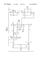
- FIG. 7 illustrates a known tri-statable output buffer
- FIG. 8 illustrates an improvement over the circuit of FIG. 7, in accordance with the present invention.
- the term “high impedance state” is defined as a state in which a device (i.e., a buffer) has a high enough impedance presented to the line so that it does not draw more than a very small current. Ideally, it will not draw any current, but a current of 10 to 20 micro amps being drawn is still considered a “high impedance state.”
- the term “low impedance state” is defined herein would ideally be zero ohms, but would also include an impedance of up to 100 ohms.
- the term “normal state” or “normal operation” is defined as the state in which there is no high voltage applied externally to the circuit's output, and it is driving output voltages between 0 (low state) and VDD (high state).
- FIG. 3 illustrates a fail-safe buffer circuit in accordance with the present invention.
- an inverter 110 comprises transistors 112 and 114 having an input node 116 and driving an output node 118 .
- Output node 118 is connected to a first input 152 of a core voltage blocking circuit 150 .
- a second input node 154 of core voltage blocking circuit 150 receives a core voltage VCORE from a core voltage power supply (not shown) via node 144 .
- An output 156 of core voltage blocking circuit 150 drives node 142 , which is connected to the gate of transistor 121 of the pull-down stage 120 .
- This circuit is essentially identical to the circuit of FIG. 2, except for the insertion of core voltage block circuit 150 between inverter 110 and pull-down stage 120 .
- FIG. 4 is circuit diagram of an example of a core voltage blocking circuit 150 of FIG. 3 in accordance with the present invention.
- An inverter 158 comprises transistor 160 connected as a diode in series with transistors 164 and 166 .
- An output node 168 of inverter 158 is connected to the gate of transistor 172 and also to the gate of transistor 174 .
- Transistors 174 and 178 are connected to form a transmission gate (“T-gate”).
- the back gate of transistor 174 terminates at output node 176 , which, utilizing a known floating-well generator circuit 179 illustrated in FIG. 5 (described in more detail below), automatically sets output node 176 equal to the greater of VDD and the core power supply voltage VCORE.
- P-channel transistors 180 and 182 are connected such that the common node between them, output node 176 , is the value of the greater of VDD and the core power supply voltage.
- transistor 182 will be on and transistor 180 will be off. This connects node 176 to VCORE.
- node 176 will always be at the most positive potential, ensuring that the parasitic diode of transistor 174 will not turn on.
- FIG. 6 A standard circuit that is used to translate low voltages to higher voltages in fast data paths is shown in FIG. 6 .
- two data inputs, A and its complement AN are the inputs from the low voltage core, e.g., VCORE of FIG. 5 . Since they are connected only to N-channel transistors 610 and 612 as shown, their voltage values in the high state are not a problem.
- transistor 610 When A is high and AN is low, transistor 610 is on and transistor 612 is off. This pulls node 614 low, turning on transistor 618 , which in turn pulls node 616 high, ensuring that transistor 620 remains off.
- the output Z will be high since node 614 is low. If A is low and AN is high, transistor 612 is on and transistor 614 is off. This pulls node 616 low, turning on transistor 620 which pulls node 614 high. The output Z is thus low.
- FIG. 6 The circuit of FIG. 6 has been found to work well, but it has a potential flaw with regard to fail-safe operation. If the core voltage VCORE fails during circuit operation while VDD is still present, both signals A and AN of FIG. 6 will be low. This turns off both transistors 610 and 612 , causing the output Z to be latched into whatever state it was in when VCORE failed. Slight differences in leakage of the various transistors could change this state from one to the other, so it is impossible to tell what the final output would be. If the enable signal to a tri-statable fail-safe output buffer is latched in the wrong state, the buffer will be on when the system expects it to be in tri-state. This results in the buffer being in a low impedance state when the system was expecting a high impedance state. This could cause the system to crash, and possibly damage the chip due to very high currents.
- FIG. 7 illustrates a prior art tri-statable output buffer that is fail-safe when VDD is not present, or when VDD is present and the tri-state enable signal EN is high.
- This circuit is disclosed and described in detail in previously-mentioned commonly assigned U.S. patent application Ser. No. 09/069,149.
- VDD voltage
- the tri-state enable signal EN is high
- node STN is low.
- nodes D and C will also be low, since transistors 738 and 736 will be turned on. This ensures that transistor 740 is on.
- the transmission gate formed by transistors 754 and 730 is also on, since node PGATE will be low as long as VDD is present.
- the NAND and NOR gates 748 and 746 control the output state of the circuit. As long as the tri-state enable signal EN is high, node H will be low and node G will be high, turning off both transistors 732 and 747 , and thus putting the output into tri-state.
- a contention situation is one where one buffer connected to a bus line pulls the bus line high while another buffer on the same bus line pulls it low. This condition results in very high currents which can severely degrade the reliability of the system.
- FIG. 8 illustrates how the use of a core voltage blocking circuit in accordance with the present invention results in an improvement over the circuit of FIG. 7 .
- a core voltage blocking circuit 800 such as that illustrated in FIG. 4 is added to the enable lead path in such a way that if VCORE fails, node H of FIG. 8 will be low and node G high, regardless of the latched state (high or low) of node EN i.e., this ensures that the FIG. 8 circuit is in tri-state. It is not necessary to add a core voltage blocking circuit to node A, since the latched state of node A does not affect the fail-safe aspect of the circuit.
Abstract
Description
Claims (12)
Priority Applications (1)
| Application Number | Priority Date | Filing Date | Title |
|---|---|---|---|
| US09/318,158 US6184700B1 (en) | 1999-05-25 | 1999-05-25 | Fail safe buffer capable of operating with a mixed voltage core |
Applications Claiming Priority (1)
| Application Number | Priority Date | Filing Date | Title |
|---|---|---|---|
| US09/318,158 US6184700B1 (en) | 1999-05-25 | 1999-05-25 | Fail safe buffer capable of operating with a mixed voltage core |
Publications (1)
| Publication Number | Publication Date |
|---|---|
| US6184700B1 true US6184700B1 (en) | 2001-02-06 |
Family
ID=23236919
Family Applications (1)
| Application Number | Title | Priority Date | Filing Date |
|---|---|---|---|
| US09/318,158 Expired - Lifetime US6184700B1 (en) | 1999-05-25 | 1999-05-25 | Fail safe buffer capable of operating with a mixed voltage core |
Country Status (1)
| Country | Link |
|---|---|
| US (1) | US6184700B1 (en) |
Cited By (16)
| Publication number | Priority date | Publication date | Assignee | Title |
|---|---|---|---|---|
| US6320406B1 (en) * | 1999-10-04 | 2001-11-20 | Texas Instruments Incorporated | Methods and apparatus for a terminated fail-safe circuit |
| US6396315B1 (en) * | 1999-05-03 | 2002-05-28 | Agere Systems Guardian Corp. | Voltage clamp for a failsafe buffer |
| US6507218B1 (en) * | 2000-03-31 | 2003-01-14 | Intel Corporation | Method and apparatus for reducing back-to-back voltage glitch on high speed data bus |
| US6650149B1 (en) | 2002-08-15 | 2003-11-18 | Pericom Semiconductor Corp. | Latched active fail-safe circuit for protecting a differential receiver |
| US20070008007A1 (en) * | 2005-07-01 | 2007-01-11 | Takatoshi Yasui | Input/output circuit device |
| US20070075748A1 (en) * | 2005-09-30 | 2007-04-05 | Dipankar Bhattacharya | Floating well circuit having enhanced latch-up performance |
| US20080036490A1 (en) * | 2006-08-11 | 2008-02-14 | Dae Gyu Kim | Semiconductor integrated circuit device with a fail-safe IO circuit and electronic device including the same |
| US7408751B1 (en) * | 2005-09-15 | 2008-08-05 | Integrated Device Technology, Inc. | Self-biased electrostatic discharge protection method and circuit |
| US20090058517A1 (en) * | 2007-09-05 | 2009-03-05 | Chia-Hui Chen | High Voltage Tolerant Input Buffer |
| US7642818B1 (en) * | 2008-10-14 | 2010-01-05 | Winbond Electronics Corp. | High voltage tolerant input circuit capable of operating at extremely low IO supply voltage |
| US20110181343A1 (en) * | 2007-11-14 | 2011-07-28 | Arm Limited | Power controlling integrated circuit and retention switching circuit |
| US8030964B1 (en) * | 2008-05-15 | 2011-10-04 | Altera Corporation | Techniques for level shifting signals |
| CN101409551B (en) * | 2008-11-21 | 2012-06-27 | 华邦电子股份有限公司 | Input circuit |
| US20140340118A1 (en) * | 2011-12-13 | 2014-11-20 | Soitec | Tristate gate |
| US10644701B1 (en) | 2019-05-21 | 2020-05-05 | Faraday Technology Corp. | Input and output circuit and self-biased circuit thereof |
| US20220239290A1 (en) * | 2021-01-28 | 2022-07-28 | Mediatek Inc. | Pad-tracking circuit design to prevent leakage current during power ramp up or ramp down of output buffer |
Citations (5)
| Publication number | Priority date | Publication date | Assignee | Title |
|---|---|---|---|---|
| US5160855A (en) | 1991-06-28 | 1992-11-03 | Digital Equipment Corporation | Floating-well CMOS output driver |
| US5446300A (en) | 1992-11-04 | 1995-08-29 | North American Philips Corporation | Semiconductor device configuration with multiple HV-LDMOS transistors and a floating well circuit |
| US5576635A (en) | 1995-02-14 | 1996-11-19 | Advanced Micro Devices, Inc. | Output buffer with improved tolerance to overvoltage |
| US5952866A (en) * | 1998-04-28 | 1999-09-14 | Lucent Technologies, Inc. | CMOS output buffer protection circuit |
| US5963083A (en) * | 1998-04-28 | 1999-10-05 | Lucent Technologies, Inc. | CMOS reference voltage generator |
-
1999
- 1999-05-25 US US09/318,158 patent/US6184700B1/en not_active Expired - Lifetime
Patent Citations (5)
| Publication number | Priority date | Publication date | Assignee | Title |
|---|---|---|---|---|
| US5160855A (en) | 1991-06-28 | 1992-11-03 | Digital Equipment Corporation | Floating-well CMOS output driver |
| US5446300A (en) | 1992-11-04 | 1995-08-29 | North American Philips Corporation | Semiconductor device configuration with multiple HV-LDMOS transistors and a floating well circuit |
| US5576635A (en) | 1995-02-14 | 1996-11-19 | Advanced Micro Devices, Inc. | Output buffer with improved tolerance to overvoltage |
| US5952866A (en) * | 1998-04-28 | 1999-09-14 | Lucent Technologies, Inc. | CMOS output buffer protection circuit |
| US5963083A (en) * | 1998-04-28 | 1999-10-05 | Lucent Technologies, Inc. | CMOS reference voltage generator |
Cited By (24)
| Publication number | Priority date | Publication date | Assignee | Title |
|---|---|---|---|---|
| US6396315B1 (en) * | 1999-05-03 | 2002-05-28 | Agere Systems Guardian Corp. | Voltage clamp for a failsafe buffer |
| US6320406B1 (en) * | 1999-10-04 | 2001-11-20 | Texas Instruments Incorporated | Methods and apparatus for a terminated fail-safe circuit |
| US6507218B1 (en) * | 2000-03-31 | 2003-01-14 | Intel Corporation | Method and apparatus for reducing back-to-back voltage glitch on high speed data bus |
| US6650149B1 (en) | 2002-08-15 | 2003-11-18 | Pericom Semiconductor Corp. | Latched active fail-safe circuit for protecting a differential receiver |
| US7388401B2 (en) * | 2005-07-01 | 2008-06-17 | Matsushita Electric Industrial Co., Ltd. | Input/output circuit device |
| US20070008007A1 (en) * | 2005-07-01 | 2007-01-11 | Takatoshi Yasui | Input/output circuit device |
| US7408751B1 (en) * | 2005-09-15 | 2008-08-05 | Integrated Device Technology, Inc. | Self-biased electrostatic discharge protection method and circuit |
| US7276957B2 (en) * | 2005-09-30 | 2007-10-02 | Agere Systems Inc. | Floating well circuit having enhanced latch-up performance |
| US20070075748A1 (en) * | 2005-09-30 | 2007-04-05 | Dipankar Bhattacharya | Floating well circuit having enhanced latch-up performance |
| US20080036490A1 (en) * | 2006-08-11 | 2008-02-14 | Dae Gyu Kim | Semiconductor integrated circuit device with a fail-safe IO circuit and electronic device including the same |
| US7656185B2 (en) * | 2006-08-11 | 2010-02-02 | Samsung Electronics Co., Ltd. | Semiconductor integrated circuit device with a fail-safe IO circuit and electronic device including the same |
| US20090058517A1 (en) * | 2007-09-05 | 2009-03-05 | Chia-Hui Chen | High Voltage Tolerant Input Buffer |
| US7564287B2 (en) * | 2007-09-05 | 2009-07-21 | Taiwan Semiconductor Manufacturing Co., Ltd. | High voltage tolerant input buffer |
| US8922247B2 (en) * | 2007-11-14 | 2014-12-30 | Arm Limited | Power controlling integrated circuit and retention switching circuit |
| US20110181343A1 (en) * | 2007-11-14 | 2011-07-28 | Arm Limited | Power controlling integrated circuit and retention switching circuit |
| US8030964B1 (en) * | 2008-05-15 | 2011-10-04 | Altera Corporation | Techniques for level shifting signals |
| US7642818B1 (en) * | 2008-10-14 | 2010-01-05 | Winbond Electronics Corp. | High voltage tolerant input circuit capable of operating at extremely low IO supply voltage |
| CN101409551B (en) * | 2008-11-21 | 2012-06-27 | 华邦电子股份有限公司 | Input circuit |
| US20140340118A1 (en) * | 2011-12-13 | 2014-11-20 | Soitec | Tristate gate |
| US9479174B2 (en) * | 2011-12-13 | 2016-10-25 | Soitec | Tristate gate |
| CN104040894B (en) * | 2011-12-13 | 2019-04-23 | 索泰克公司 | Tri-state gate, circuit and semiconductor structure including tri-state gate |
| US10644701B1 (en) | 2019-05-21 | 2020-05-05 | Faraday Technology Corp. | Input and output circuit and self-biased circuit thereof |
| US20220239290A1 (en) * | 2021-01-28 | 2022-07-28 | Mediatek Inc. | Pad-tracking circuit design to prevent leakage current during power ramp up or ramp down of output buffer |
| US11652476B2 (en) * | 2021-01-28 | 2023-05-16 | Mediatek Inc. | Pad-tracking circuit design to prevent leakage current during power ramp up or ramp down of output buffer |
Similar Documents
| Publication | Publication Date | Title |
|---|---|---|
| US6184700B1 (en) | Fail safe buffer capable of operating with a mixed voltage core | |
| US5206544A (en) | CMOS off-chip driver with reduced signal swing and reduced power supply disturbance | |
| US5629634A (en) | Low-power, tristate, off-chip driver circuit | |
| JP3796034B2 (en) | Level conversion circuit and semiconductor integrated circuit device | |
| US10305474B2 (en) | High voltage output driver with low voltage devices | |
| US6487687B1 (en) | Voltage level shifter with testable cascode devices | |
| US5828262A (en) | Ultra low power pumped n-channel output buffer with self-bootstrap | |
| US6060906A (en) | Bidirectional buffer with active pull-up/latch circuit for mixed-voltage applications | |
| JPH07212213A (en) | Low-power output buffer | |
| US6144221A (en) | Voltage tolerant interface circuit | |
| US5914844A (en) | Overvoltage-tolerant input-output buffers having a switch configured to isolate a pull up transistor from a voltage supply | |
| US5723987A (en) | Level shifting output buffer with p channel pulldown transistors which are bypassed | |
| JPH088719A (en) | Mixed voltage output buffer circuit | |
| US6803789B1 (en) | High voltage tolerant output buffer | |
| US5966035A (en) | High voltage tolerable input buffer | |
| US6313672B1 (en) | Over-voltage tolerant integrated circuit I/O buffer | |
| US7355447B2 (en) | Level shifter circuit | |
| US6265931B1 (en) | Voltage reference source for an overvoltage-tolerant bus interface | |
| KR100211758B1 (en) | Multi-power data buffer | |
| JP3566773B2 (en) | Output buffer circuit with power down function | |
| JP2001313560A (en) | Protection circuit for dual power supply circuit | |
| US6496054B1 (en) | Control signal generator for an overvoltage-tolerant interface circuit on a low voltage process | |
| US6201428B1 (en) | 5-volt tolerant 3-volt drive push-pull buffer/driver | |
| US7123053B1 (en) | Circuitry for providing overvoltage backdrive protection | |
| US5966044A (en) | Pull-up circuit and semiconductor device using the same |
Legal Events
| Date | Code | Title | Description |
|---|---|---|---|
| AS | Assignment |
Owner name: LUCENT TECHNOLOGIES, INC., NEW JERSEY Free format text: ASSIGNMENT OF ASSIGNORS INTEREST;ASSIGNOR:MORRIS, BERNARD L.;REEL/FRAME:009993/0983 Effective date: 19990524 |
|
| STCF | Information on status: patent grant |
Free format text: PATENTED CASE |
|
| FPAY | Fee payment |
Year of fee payment: 4 |
|
| AS | Assignment |
Owner name: AGERE SYSTEMS INC., PENNSYLVANIA Free format text: ASSIGNMENT OF ASSIGNORS INTEREST;ASSIGNOR:LUCENT TECHNOLOGIES INC.;REEL/FRAME:019419/0954 Effective date: 20010130 |
|
| FPAY | Fee payment |
Year of fee payment: 8 |
|
| FPAY | Fee payment |
Year of fee payment: 12 |
|
| AS | Assignment |
Owner name: DEUTSCHE BANK AG NEW YORK BRANCH, AS COLLATERAL AG Free format text: PATENT SECURITY AGREEMENT;ASSIGNORS:LSI CORPORATION;AGERE SYSTEMS LLC;REEL/FRAME:032856/0031 Effective date: 20140506 |
|
| AS | Assignment |
Owner name: LSI CORPORATION, CALIFORNIA Free format text: TERMINATION AND RELEASE OF SECURITY INTEREST IN PATENT RIGHTS (RELEASES RF 032856-0031);ASSIGNOR:DEUTSCHE BANK AG NEW YORK BRANCH, AS COLLATERAL AGENT;REEL/FRAME:037684/0039 Effective date: 20160201 Owner name: AGERE SYSTEMS LLC, PENNSYLVANIA Free format text: TERMINATION AND RELEASE OF SECURITY INTEREST IN PATENT RIGHTS (RELEASES RF 032856-0031);ASSIGNOR:DEUTSCHE BANK AG NEW YORK BRANCH, AS COLLATERAL AGENT;REEL/FRAME:037684/0039 Effective date: 20160201 |
|
| AS | Assignment |
Owner name: BANK OF AMERICA, N.A., AS COLLATERAL AGENT, NORTH CAROLINA Free format text: PATENT SECURITY AGREEMENT;ASSIGNOR:AVAGO TECHNOLOGIES GENERAL IP (SINGAPORE) PTE. LTD.;REEL/FRAME:037808/0001 Effective date: 20160201 Owner name: BANK OF AMERICA, N.A., AS COLLATERAL AGENT, NORTH Free format text: PATENT SECURITY AGREEMENT;ASSIGNOR:AVAGO TECHNOLOGIES GENERAL IP (SINGAPORE) PTE. LTD.;REEL/FRAME:037808/0001 Effective date: 20160201 |
|
| AS | Assignment |
Owner name: AVAGO TECHNOLOGIES GENERAL IP (SINGAPORE) PTE. LTD., SINGAPORE Free format text: TERMINATION AND RELEASE OF SECURITY INTEREST IN PATENTS;ASSIGNOR:BANK OF AMERICA, N.A., AS COLLATERAL AGENT;REEL/FRAME:041710/0001 Effective date: 20170119 Owner name: AVAGO TECHNOLOGIES GENERAL IP (SINGAPORE) PTE. LTD Free format text: TERMINATION AND RELEASE OF SECURITY INTEREST IN PATENTS;ASSIGNOR:BANK OF AMERICA, N.A., AS COLLATERAL AGENT;REEL/FRAME:041710/0001 Effective date: 20170119 |
|
| AS | Assignment |
Owner name: AVAGO TECHNOLOGIES INTERNATIONAL SALES PTE. LIMITE Free format text: ASSIGNMENT OF ASSIGNORS INTEREST;ASSIGNOR:AVAGO TECHNOLOGIES GENERAL IP (SINGAPORE) PTE. LTD.;REEL/FRAME:047022/0620 Effective date: 20180509 |
|
| AS | Assignment |
Owner name: AVAGO TECHNOLOGIES INTERNATIONAL SALES PTE. LIMITE Free format text: CORRECTIVE ASSIGNMENT TO CORRECT THE NATURE OF CONVEYANCE AND EFFECTIVE DATE PREVIOUSLY RECORDED ON REEL 047022 FRAME 0620. ASSIGNOR(S) HEREBY CONFIRMS THE MERGER;ASSIGNOR:AVAGO TECHNOLOGIES GENERAL IP (SINGAPORE) PTE. LTD.;REEL/FRAME:047185/0643 Effective date: 20180509 |
|
| AS | Assignment |
Owner name: AVAGO TECHNOLOGIES INTERNATIONAL SALES PTE. LIMITE Free format text: CORRECTIVE ASSIGNMENT TO CORRECT THE EFFECTIVE DATE PREVIOUSLY RECORDED ON REEL 047185 FRAME 0643. ASSIGNOR(S) HEREBY CONFIRMS THE MERGER;ASSIGNOR:AVAGO TECHNOLOGIES GENERAL IP (SINGAPORE) PTE. LTD.;REEL/FRAME:047476/0845 Effective date: 20180905 |
|
| AS | Assignment |
Owner name: AVAGO TECHNOLOGIES INTERNATIONAL SALES PTE. LIMITE Free format text: CORRECTIVE ASSIGNMENT TO CORRECT THE EFFECTIVE DATE OF MERGER PREVIOUSLY RECORDED AT REEL: 047185 FRAME: 0643. ASSIGNOR(S) HEREBY CONFIRMS THE CORRECTIVE MERGER;ASSIGNOR:AVAGO TECHNOLOGIES GENERAL IP (SINGAPORE) PTE. LTD.;REEL/FRAME:047959/0296 Effective date: 20180905 |