US6196827B1 - Swing arm stabilizing cage - Google Patents
Swing arm stabilizing cage Download PDFInfo
- Publication number
- US6196827B1 US6196827B1 US09/208,731 US20873198A US6196827B1 US 6196827 B1 US6196827 B1 US 6196827B1 US 20873198 A US20873198 A US 20873198A US 6196827 B1 US6196827 B1 US 6196827B1
- Authority
- US
- United States
- Prior art keywords
- tube
- extrusion
- frame
- pivot
- swing arm
- Prior art date
- Legal status (The legal status is an assumption and is not a legal conclusion. Google has not performed a legal analysis and makes no representation as to the accuracy of the status listed.)
- Expired - Lifetime
Links
Images


Classifications
-
- B—PERFORMING OPERATIONS; TRANSPORTING
- B29—WORKING OF PLASTICS; WORKING OF SUBSTANCES IN A PLASTIC STATE IN GENERAL
- B29C—SHAPING OR JOINING OF PLASTICS; SHAPING OF MATERIAL IN A PLASTIC STATE, NOT OTHERWISE PROVIDED FOR; AFTER-TREATMENT OF THE SHAPED PRODUCTS, e.g. REPAIRING
- B29C48/00—Extrusion moulding, i.e. expressing the moulding material through a die or nozzle which imparts the desired form; Apparatus therefor
- B29C48/25—Component parts, details or accessories; Auxiliary operations
- B29C48/88—Thermal treatment of the stream of extruded material, e.g. cooling
- B29C48/90—Thermal treatment of the stream of extruded material, e.g. cooling with calibration or sizing, i.e. combined with fixing or setting of the final dimensions of the extruded article
- B29C48/907—Thermal treatment of the stream of extruded material, e.g. cooling with calibration or sizing, i.e. combined with fixing or setting of the final dimensions of the extruded article using adjustable calibrators, e.g. the dimensions of the calibrator being changeable
-
- B—PERFORMING OPERATIONS; TRANSPORTING
- B29—WORKING OF PLASTICS; WORKING OF SUBSTANCES IN A PLASTIC STATE IN GENERAL
- B29C—SHAPING OR JOINING OF PLASTICS; SHAPING OF MATERIAL IN A PLASTIC STATE, NOT OTHERWISE PROVIDED FOR; AFTER-TREATMENT OF THE SHAPED PRODUCTS, e.g. REPAIRING
- B29C48/00—Extrusion moulding, i.e. expressing the moulding material through a die or nozzle which imparts the desired form; Apparatus therefor
- B29C48/03—Extrusion moulding, i.e. expressing the moulding material through a die or nozzle which imparts the desired form; Apparatus therefor characterised by the shape of the extruded material at extrusion
- B29C48/06—Rod-shaped
-
- B—PERFORMING OPERATIONS; TRANSPORTING
- B29—WORKING OF PLASTICS; WORKING OF SUBSTANCES IN A PLASTIC STATE IN GENERAL
- B29C—SHAPING OR JOINING OF PLASTICS; SHAPING OF MATERIAL IN A PLASTIC STATE, NOT OTHERWISE PROVIDED FOR; AFTER-TREATMENT OF THE SHAPED PRODUCTS, e.g. REPAIRING
- B29C48/00—Extrusion moulding, i.e. expressing the moulding material through a die or nozzle which imparts the desired form; Apparatus therefor
- B29C48/03—Extrusion moulding, i.e. expressing the moulding material through a die or nozzle which imparts the desired form; Apparatus therefor characterised by the shape of the extruded material at extrusion
- B29C48/07—Flat, e.g. panels
- B29C48/08—Flat, e.g. panels flexible, e.g. films
-
- B—PERFORMING OPERATIONS; TRANSPORTING
- B29—WORKING OF PLASTICS; WORKING OF SUBSTANCES IN A PLASTIC STATE IN GENERAL
- B29C—SHAPING OR JOINING OF PLASTICS; SHAPING OF MATERIAL IN A PLASTIC STATE, NOT OTHERWISE PROVIDED FOR; AFTER-TREATMENT OF THE SHAPED PRODUCTS, e.g. REPAIRING
- B29C48/00—Extrusion moulding, i.e. expressing the moulding material through a die or nozzle which imparts the desired form; Apparatus therefor
- B29C48/03—Extrusion moulding, i.e. expressing the moulding material through a die or nozzle which imparts the desired form; Apparatus therefor characterised by the shape of the extruded material at extrusion
- B29C48/09—Articles with cross-sections having partially or fully enclosed cavities, e.g. pipes or channels
- B29C48/10—Articles with cross-sections having partially or fully enclosed cavities, e.g. pipes or channels flexible, e.g. blown foils
-
- B—PERFORMING OPERATIONS; TRANSPORTING
- B29—WORKING OF PLASTICS; WORKING OF SUBSTANCES IN A PLASTIC STATE IN GENERAL
- B29C—SHAPING OR JOINING OF PLASTICS; SHAPING OF MATERIAL IN A PLASTIC STATE, NOT OTHERWISE PROVIDED FOR; AFTER-TREATMENT OF THE SHAPED PRODUCTS, e.g. REPAIRING
- B29C48/00—Extrusion moulding, i.e. expressing the moulding material through a die or nozzle which imparts the desired form; Apparatus therefor
- B29C48/25—Component parts, details or accessories; Auxiliary operations
- B29C48/88—Thermal treatment of the stream of extruded material, e.g. cooling
- B29C48/90—Thermal treatment of the stream of extruded material, e.g. cooling with calibration or sizing, i.e. combined with fixing or setting of the final dimensions of the extruded article
- B29C48/901—Thermal treatment of the stream of extruded material, e.g. cooling with calibration or sizing, i.e. combined with fixing or setting of the final dimensions of the extruded article of hollow bodies
- B29C48/903—Thermal treatment of the stream of extruded material, e.g. cooling with calibration or sizing, i.e. combined with fixing or setting of the final dimensions of the extruded article of hollow bodies externally
-
- B—PERFORMING OPERATIONS; TRANSPORTING
- B29—WORKING OF PLASTICS; WORKING OF SUBSTANCES IN A PLASTIC STATE IN GENERAL
- B29C—SHAPING OR JOINING OF PLASTICS; SHAPING OF MATERIAL IN A PLASTIC STATE, NOT OTHERWISE PROVIDED FOR; AFTER-TREATMENT OF THE SHAPED PRODUCTS, e.g. REPAIRING
- B29C48/00—Extrusion moulding, i.e. expressing the moulding material through a die or nozzle which imparts the desired form; Apparatus therefor
- B29C48/25—Component parts, details or accessories; Auxiliary operations
- B29C48/88—Thermal treatment of the stream of extruded material, e.g. cooling
- B29C48/911—Cooling
- B29C48/9115—Cooling of hollow articles
- B29C48/912—Cooling of hollow articles of tubular films
- B29C48/913—Cooling of hollow articles of tubular films externally
-
- B—PERFORMING OPERATIONS; TRANSPORTING
- B29—WORKING OF PLASTICS; WORKING OF SUBSTANCES IN A PLASTIC STATE IN GENERAL
- B29C—SHAPING OR JOINING OF PLASTICS; SHAPING OF MATERIAL IN A PLASTIC STATE, NOT OTHERWISE PROVIDED FOR; AFTER-TREATMENT OF THE SHAPED PRODUCTS, e.g. REPAIRING
- B29C48/00—Extrusion moulding, i.e. expressing the moulding material through a die or nozzle which imparts the desired form; Apparatus therefor
- B29C48/25—Component parts, details or accessories; Auxiliary operations
- B29C48/88—Thermal treatment of the stream of extruded material, e.g. cooling
- B29C48/911—Cooling
- B29C48/9135—Cooling of flat articles, e.g. using specially adapted supporting means
Definitions
- the present invention relates to the fabrication and processing of plastic film, and is more specifically directed to stabilizers for maintaining a tubular extrusion of blown plastic film, that is, a bubble, on a predetermined path during the extrusion process.
- the invention is more particularly concerned with improvements to an external guide or stabilizer arrangement that permits the aperture of the stabilizer to be adjusted, and which minimizes or eliminates problems caused by friction or film distortion as the extruded thermoplastic material is drawn through the guide stabilizer or sizing cage.
- Polyethylene film or films of other thermoplastic materials are produced using a blown film process, in which molten thermoplastic material is fed to an annular extrusion die and the latter produces a tubular extrusion, i.e. bubble, of the material, which is drawn upwards and solidifies into film.
- An air jet incorporated in the die injects air into the interior of the extrusion to inflate the bubble or tube.
- the film in the extrusion is initially somewhat fluid, and inflates to a larger diameter, with a correspondingly thinner wall, cooling and solidifying when a predetermined thickness is reached. The process is controlled and adjusted so that the film has a uniform thickness, and this basic process is well known in the art.
- the tubular extrusion is drawn upwards and flattened between a pair of rollers, i.e., nip rollers, that are positioned above the die.
- a collapsing frame is provided to urge opposite sides of the tubular extrusion towards one another just before the tube reaches the nip rollers.
- the collapsing frame may consist of a pair of opposed arrays of horizontal collapsing boards of any of a number of well-known configurations, and one arrangement is discussed in U.S. Pat. No. 4,943,226, granted Jul. 24, 1990.
- the film exits the nip rollers as multiple-thicknesses of film, and the film proceeds from there to various cutting, printing, rolling, or other equipment.
- the thickness, as well as strength and other properties, of the produced film be as uniform as possible. It is also necessary to the quality of the film that it be relatively free of weak regions and tears.
- stabilizer arrangements are used to keep the tubular extrusion confined to a well-defined travel path as it proceeds from the die to the nip rollers.
- Guide cages or other external stabilizers can be positioned outside the bubble for this purpose.
- internal guide members can disposed atop the extrusion die and within the bubble, both to prevent the tubular extrusion from drifting off the axis of travel, and also to assist in the direction of air flow within the bubble from the die.
- an external stabilizer takes the form of a series of banks of bowed arms positioned at intervals around the tubular extrusion.
- each arm carries a row of rollers made of PTFE (Teflon).
- the arms are positioned just out of contact with the bubble, or else in light contact.
- the film contacts the arms and rollers on that side.
- the rollers turn, and also push the extrusion back towards the vertical axis.
- the extruded plastic is highly abrasive, so that when the bubble moves vertically past the rollers at high speed, it tends to wear the rollers flat on one side. Also, because the rollers are positioned along a curve, the adjacent rollers touch on the bubble side, but are spaced from one another on the outer side of the arms. Therefore, there is a tendency for the rollers to pinch the film as it moves past, creating snags and tears. This is especially the case where the rollers exhibit wear and so that material has eroded away. Furthermore, it is difficult and expensive to replace worn PTFE rollers, and replacement typically involves replacing all the rollers along the entire bowed arm. In addition, the materials and construction involved make the external stabilizer of this design rather expensive.
- a recognized problem in the blown film art is that blown film has different stretch and strength characteristics in the axial or machine direction from what is achieved in the transverse direction, i.e., circumferentially around the extrusion. This occurs because is has been difficult to control the expansion of the bubble in both directions at the same time.
- the strength in the machine direction, or MD should be the same as the strength in the transverse direction, or TD. Stabilizing the position of the extrusion or bubble would help in this regard. Also, controlling rotation of the bubble as it rises will affect these properties.
- film materials of different composition, and films of different thickness may require more or less rotation, so some means should be provided to change the amount of rotation that the stabilizer induces onto the extruded bubble.
- improved external stabilizer and sizing cage means are provided for plastic film blowing apparatus of the type in which a tubular extrusion die is fed with a supply of a molten thermoplastic polymer and extrudes a tube of the molten polymer.
- the die injects air to inflate the tube and expand the wall of the tube into a film of a predetermined film thickness.
- Nip roller means positioned above the die at the top of the bubble draw the tube vertically upward from the die and collapse and flatten the film.
- the improved external stabilizer arrangement is positioned on a frame surrounding the extruded tube above the die means to keep the tube aligned on a predetermined path as the tube is drawn upwards, and has a plurality of swing arms arranged on the frame to define an iris aperture. Pivot means on the frame swing the arms toward and away from the bubble axis to reduce and increase the size of the aperture.
- each such swing arm includes an elongated extrusion of a light-weight material (e.g., aluminum or aluminum alloy) having a pivot end mounted to pivot means on the frame and a free end.
- swing arms being rigid, unitary extrusions
- a portion of the unitary extrusion not axially offset from the pivot end and situated between the pivot end and the free end of the extrusion defines the iris aperture (as shown in the figures).
- This extrusion has a profile that is rounded on a side that faces the extruded tube so that the elongated extrusion has a rounded front, or film-facing surface.
- a wear resistant material is situated on the rounded front surface of the extrusion, such that the extruded tube of film slides over the wear material.
- the wear material can take the form of a low-friction plastic wear cap or cover having a profile that matches the shape of the front side of the aluminum extrusion.
- the plastic wear covers can be replaced when worn simply by snapping or sliding them off and replacing them in similar fashion with fresh wear covers.
- the metal extrusions can be provided with a low-friction, wear-resistant surface treatment rather than the plastic wear cover.
- the arms each have a straight portion at the pivot end, a bowed portion after the straight portion, and a recurve portion at the free end.
- the bowed portion has a center of curvature on the side towards said polymer tube and the recurve portion has a center of curvature on the side away from the polymer tube.
- a flow of a coolant such as water
- a coolant such as water
- the swing arm extrusion has a generally mushroom-shaped profile with a curved cap portion forming its rounded front surface, and a stem portion behind it.
- the stem portion is formed of first and second extruded tubes, and one can be connected with coolant supply piping and the other connected with coolant return piping.
- each swing arm has a pivot member in the form of a stackable segment having a body portion, a pin member on one end, and a clamp member situated on the opposite end.
- These can have index marks (e.g., at ⁇ fraction (1/32) ⁇ ′′ increments) so that the stacking segment can be aligned or offset, as desired, with respect to the one just above and the one just below.
- FIG. 1 is a perspective view of a blown film extrusion arrangement showing an external stabilizer or sizing cage of the prior art.
- FIG. 2 is a perspective view of the stabilizer according to an embodiment of the invention.
- FIG. 3 is an enlargement of a portion of FIG. 2 .
- FIG. 4 is an assembly view showing stacking segments of this embodiment.
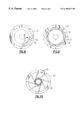
- FIG. 5 is a plan view of one of the swing arms this embodiment.
- FIG. 6 is a cross-section of the swing arm of this embodiment taken at 6 — 6 of FIG. 5 .
- FIG. 7 explains coolant flow through the swing arm.
- FIGS. 8, 9 , and 10 are plan views showing swing arm positions for various size iris apertures.
- FIG. 1 illustrates a blown film extrusion assembly that includes an external stabilizer of this invention and may also include an internal stabilizer (not shown) according to the prior art.
- an extrusion die 10 is supplied with a molten thermoplastic material, e.g. polyethylene, polypropylene, PVC, or another thermoplastic resin.
- the die 10 has a circular or annular opening, and an air injection jet is disposed within the opening.
- the die 10 produces an extruded tube 12 or bubble of the molten material, which is drawn upwards and inflates until the wall of the extrusion is expanded to a design thickness.
- the film thickness can typically be in a range from about 0.3 mils to several mils, depending on the intended end use for the plastic film.
- the die 10 is rotated during extrusion so as to avoid longitudinal weak areas and to increase the film strength in the transverse direction (TD).
- TD transverse direction
- a collapsing frame 14 is provided well above the die 10 to urge opposite sides of the tubular extrusion 12 towards one another.
- a suitable design for a collapsing frame is described in U.S. Pat. No. 4,943,226.
- a pair of nip rollers or pinch rollers 16 are disposed above the collapser to flatten the tube into a multiple thickness of film. These nip rollers also draw the extrusion or bubble upward at a controlled rate.
- the elevation of the nip rollers above the die 10 can be forty feet or more.
- An arrangement 18 of guide rollers directs the travel of the film to a subsequent processing stage, which is not shown here.
- the travel path of the tubular extrusion can drift away from the axis between the die and rollers. This drift can lead to unacceptable irregularities, e.g., weak regions, tears, or pulls in the film product.
- the blown film arrangement typically will employ means to stabilize the path of vertical travel of the extrusion 12 . This can be below the frost line where expansion occurs, as well as above the frost line.
- These means can include internal stabilizers, external stabilizers, or some combination of the two.
- an external stabilizer 20 is employed above the frost line to control or limit transverse drift. Because of the heat carried by the molten plastic, some type of heat management is needed for the external stabilizer 20 . In the absence of heat removal, the heat of the extrusion can accumulate and can actually damage the film, or can damage the equipment, including the external stabilizer.
- the external stabilizer 20 incorporates a frame 22 (See FIG. 2) comprising at least an upper ring 24 and a lower ring 26 , with a number of stabilizer stacks 28 disposed at regular intervals, here, for example intervals of 45 degrees, so that there are eight of these stacks 28 .
- Each stack is made up of two or more stack segments 30 joined end to end (See FIGS. 3 and 4 ), and each of which carries a swing arm 32 .
- Each arm has a pivot end mounted in the stack segment, a straight portion, a bowed or curved or portion that contacts the extrusion or bubble 12 , and a recurve portion at the free end that curves away from the bubble. This is discussed below in reference to FIG. 5 .
- the frame 22 can include a mechanism to rotate the stacks 28 to swing the arms 32 in or out to accommodate the size of the plastic film extrusion or bubble 12 .
- This can be an inextensible belt drive 31 surrounding the frame 22 and contacting toothed timing wheels, for example, on the respective stacks 28 .
- a gear mechanism could be employed.
- the arms 32 pivot in or out so as to define an iris aperture about the axis of the tubular extrusion. The size of this aperture is selected for the extrusion size and the polymer material.
- FIGS. 1 and 2 Also shown in FIGS. 1 and 2 is a set of rotatable vertical threaded rods 34 that pass through female threaded members or threaded openings in the frame 22 . These are rotated to elevate or lower the stabilizer 20 in respect to the extruded bubble so as to optimize the vertical positioning of the stabilizer.
- each arm 32 has a straight portion 36 extending from the pivot end (here held in stack segment 30 ) for about half the length of the arm. Then there is a curved portion 38 that is curved in the circumferential direction about the axis of the extrusion 12 , and then a short recurve portion 40 at the free end, i.e., curved away from the extrusion axis.
- the swing arm 32 can favorably have a mushroom-shaped profile. This can be extruded of aluminum or an aluminum alloy or other lightweight material. This is similar to the profile of the bow arm shown in commonly assigned co-pending U.S. patent application Ser. No. 09/192,343, now U.S. Pat. No.
- the arm 32 has a top or cap portion 44 with an arcuate cross section.
- a stem portion 46 disposed behind this has a round tubular portion 48 adjacent to the cap portion 44 and actually merged into it.
- a liquid coolant e.g., water, can flow through the round tubular portion 48 , and then return through the square portion 50 .
- FIG. 1 a liquid coolant, e.g., water
- an end cap 52 can be fitted at the free end of the swing arm 32 , so that there is a coolant path defined within the arm, with the round tube portion 48 , adjacent the cap portion 44 , serving as the main heat exchange tube and the square tube 50 serving as the return conduit.
- Piping is provided to each of the stacking segments 30 , including a supply tube 54 and a return tube 56 , as shown in FIG. 3 . These are connected by means of hoses and tubes to coolant supply and return reservoirs (not shown).
- the coolant is connected in series to the swing arms in each stack, so that return tube 56 of one stacking segment 30 feeds the supply tube 54 of the next adjacent stacking segment.
- the cap or cover portion 44 of each of the swing arms 32 is provided with a low-friction, wear resistant surface.
- a low-friction surface treatment is incorporated into the film-facing surface of this cap portion.
- Many suitable low-friction treatments are known, including hard coats, ceramic impregnations, and other similar techniques.
- a surface treatment that has been found to be highly suited for this is known as SM-24, available from Luke Engineering of Wadsworth, Ohio.
- the cap portion of the extruded swing arm can be fitted with a removable wear cover 57 , shown in ghost. This may have a profile similar to that of the arcuate cap portion 44 , and is adapted to snap in place onto the arcuate portion 44 .
- the wear cover can be extruded or molded of a low-friction, semi-rigid plastic material, one example of which is Delrin filled with a lubricant filler.
- a low-friction, semi-rigid plastic material one example of which is Delrin filled with a lubricant filler.
- suitable materials are discussed in my earlier U.S. Pat. Nos. 5,700,489 and 5,585,120.
- the segments 30 each have a central block-shaped body portion 58 with a cylindrical pin member 60 disposed at an upper end of the body portion and a sleeve fitting 62 at its lower end.
- the sleeve fitting serves as a clamp member for non-rotationally gripping the pin member of next stackable segment below it.
- the body portion 58 is marked with indicia so that the angular position of the segment relative to the next segment can be established.
- matching indicia 70 on the clamp portion 62 can be incremented, e.g., at one-degree intervals or at ⁇ fraction (1/32) ⁇ -inch intervals, and serve as scale angulation indicia for permitting adjacent stacked segments to be angularly offset from one another by a selected amount.
- the pivot end of the associated swing arm 32 is fitted into a suitably shaped opening 72 in the body of the stacking segment, on the side opposite the coolant piping 54 , 56 .
- the stackable segments 30 each include suitable cavities and pathways for linking the coolant inlet pipe 54 and a coolant outlet pipe 56 to the round and square tube portions 48 , 50 of the associated swing arm 32 .
- each swing arm 32 (only one is shown here) in each row can be pivoted outward (as in solid lines) for a large iris aperture, or can be pivoted inward (as shown in broken line) towards the bubble axis for a smaller iris aperture.
- the configuration of the swing arms at a given level can be open for a large iris aperture (FIG. 9) or can be closed in for a smaller iris aperture (FIG. 10 ). Because the stacking segments 30 in each stack 28 can be angularly offset from one another, the iris aperture can open or close gradually from one level or row to the next.
- the swing arms 32 can be angled slightly upwards from their mounts on the respective stacking segments. This orients the swing arms 32 at a predetermined non-zero helix angle, and can induce rotation of the extruded tube or bubble 12 as the same is drawn upwards past the external stabilizer 20 .
- the segments 30 can provide for adjustment of the pitch, so that the helix angle can be changed when necessary.
- coolant water is fed first to the top row of swing arms 32 , and then to each row beneath in series, proceeding in through the round tube 48 and then out through the square tube 50 .
- the intake water for the top row is at a temperature of 40 degrees F
- the discharge water from the bottom row is 140 degrees F.
- This degree of cooling of the film improves the quality of the film, and creates more consistent film, resulting in less scrap or spoilage in subsequent manufacturing steps. Cooling also reduces the coefficient of friction of the surface treatment on the film-facing surface of the swing arm 32 .
- the type of surface treatment on the swing arm, or the need to use or not to use wear covers, depends on the type of film material being processed.
- the coolant in this example is water, but another liquid coolant may be used, as may be air or another gas, as appropriate.
Abstract
Description
Claims (19)
Priority Applications (1)
| Application Number | Priority Date | Filing Date | Title |
|---|---|---|---|
| US09/208,731 US6196827B1 (en) | 1998-12-09 | 1998-12-09 | Swing arm stabilizing cage |
Applications Claiming Priority (1)
| Application Number | Priority Date | Filing Date | Title |
|---|---|---|---|
| US09/208,731 US6196827B1 (en) | 1998-12-09 | 1998-12-09 | Swing arm stabilizing cage |
Publications (1)
| Publication Number | Publication Date |
|---|---|
| US6196827B1 true US6196827B1 (en) | 2001-03-06 |
Family
ID=22775804
Family Applications (1)
| Application Number | Title | Priority Date | Filing Date |
|---|---|---|---|
| US09/208,731 Expired - Lifetime US6196827B1 (en) | 1998-12-09 | 1998-12-09 | Swing arm stabilizing cage |
Country Status (1)
| Country | Link |
|---|---|
| US (1) | US6196827B1 (en) |
Cited By (11)
| Publication number | Priority date | Publication date | Assignee | Title |
|---|---|---|---|---|
| US20020076459A1 (en) * | 2000-04-07 | 2002-06-20 | Joseph Daniel R. | Method and apparatus for automatic control of cage size in an extruded film production line |
| US20040096531A1 (en) * | 2002-11-18 | 2004-05-20 | (Pearl Technologies, Inc.) | Oscillating guide cage |
| DE102005003860A1 (en) * | 2005-01-27 | 2006-08-03 | Egeplast Werner Strumann Gmbh & Co. Kg | Calibration head for extrusion process producing plastic pipes, tubes or films has die plates with sections of non-circular arc shape in contact with extrudate |
| US20090304840A1 (en) * | 2005-12-21 | 2009-12-10 | Holger Frische | Sizing Cage Adjustment |
| CN105500682A (en) * | 2014-09-25 | 2016-04-20 | 尚宏机械工业有限公司 | Adjustment control device for blown bag width |
| US20170203474A1 (en) * | 2016-01-15 | 2017-07-20 | Addex, Inc. | High performance cooling system |
| US20170203488A1 (en) * | 2016-01-15 | 2017-07-20 | Addex, Inc. | High performance cooling system |
| US20180043601A1 (en) * | 2015-03-02 | 2018-02-15 | Syncro S.R.L. | Calibration cage for the production of blown films |
| US11104054B2 (en) | 2016-01-15 | 2021-08-31 | Addex, Inc. | High performance cooling system |
| CN114206581A (en) * | 2019-06-03 | 2022-03-18 | Kdesign有限公司 | Device for guiding a membrane tube |
| US20220286575A1 (en) * | 2019-05-31 | 2022-09-08 | Canon Kabushiki Kaisha | Sheet discharging apparatus, image reading apparatus, and image forming apparatus |
Citations (14)
| Publication number | Priority date | Publication date | Assignee | Title |
|---|---|---|---|---|
| US3749540A (en) * | 1969-10-08 | 1973-07-31 | Windmoeller & Hoelscher | Apparatus for air-cooling a tubular plastics film blown by a blowhead |
| US3980418A (en) * | 1975-09-05 | 1976-09-14 | Gloucester Engineering Co. Inc. | Guide assembly for air-expanded thermoplastic tubes |
| US4355966A (en) | 1981-05-04 | 1982-10-26 | E. B. Westlake, Jr. | Automatic control of bubble size in blown film |
| US4388061A (en) | 1981-07-17 | 1983-06-14 | Macro Engineering Company Ltd. | Guide assembly for cylindrical plastic tubes |
| US4408970A (en) | 1979-12-19 | 1983-10-11 | Mobil Oil Corporation | Stabilizing air ring apparatus |
| US4650407A (en) * | 1985-05-06 | 1987-03-17 | Tomi Machinery Manufacturing Co., Ltd. | Cooling and guiding device for thermoplastic synthetic resin films |
| US4717323A (en) | 1985-09-07 | 1988-01-05 | Karl Veit Holger | Device for cooling a foil tubing |
| US4749346A (en) * | 1986-10-30 | 1988-06-07 | Mirek Planeta | Apparatus for the production of plastic film |
| US4793790A (en) * | 1986-10-01 | 1988-12-27 | Klaus Reinhold | Apparatus for supporting tubular films of thermoplastic material |
| US4815957A (en) * | 1987-05-09 | 1989-03-28 | Reifenhauser Gmbh & Co. Maschinenfabrik | Apparatus for calibrating a tubular foil balloon |
| US4943226A (en) * | 1988-09-19 | 1990-07-24 | Pottorff Earl T | Cover for collapsing board |
| US5585120A (en) * | 1994-12-05 | 1996-12-17 | Pearl Technologies, Inc. | Extriuded metal collapsing boards with replaceable wear plates |
| US5700489A (en) | 1996-04-08 | 1997-12-23 | Pearl Technologies, Inc. | Bubble stabilizer and sizing cage with wear strips |
| US6113026A (en) * | 1998-11-16 | 2000-09-05 | Pearl Technologies, Inc. | Bow spreader bar |
-
1998
- 1998-12-09 US US09/208,731 patent/US6196827B1/en not_active Expired - Lifetime
Patent Citations (15)
| Publication number | Priority date | Publication date | Assignee | Title |
|---|---|---|---|---|
| US3749540A (en) * | 1969-10-08 | 1973-07-31 | Windmoeller & Hoelscher | Apparatus for air-cooling a tubular plastics film blown by a blowhead |
| US3980418A (en) * | 1975-09-05 | 1976-09-14 | Gloucester Engineering Co. Inc. | Guide assembly for air-expanded thermoplastic tubes |
| US4408970A (en) | 1979-12-19 | 1983-10-11 | Mobil Oil Corporation | Stabilizing air ring apparatus |
| US4355966A (en) | 1981-05-04 | 1982-10-26 | E. B. Westlake, Jr. | Automatic control of bubble size in blown film |
| US4388061A (en) | 1981-07-17 | 1983-06-14 | Macro Engineering Company Ltd. | Guide assembly for cylindrical plastic tubes |
| US4650407A (en) * | 1985-05-06 | 1987-03-17 | Tomi Machinery Manufacturing Co., Ltd. | Cooling and guiding device for thermoplastic synthetic resin films |
| US4717323A (en) | 1985-09-07 | 1988-01-05 | Karl Veit Holger | Device for cooling a foil tubing |
| US4793790A (en) * | 1986-10-01 | 1988-12-27 | Klaus Reinhold | Apparatus for supporting tubular films of thermoplastic material |
| US4749346A (en) * | 1986-10-30 | 1988-06-07 | Mirek Planeta | Apparatus for the production of plastic film |
| US4815957A (en) * | 1987-05-09 | 1989-03-28 | Reifenhauser Gmbh & Co. Maschinenfabrik | Apparatus for calibrating a tubular foil balloon |
| US4943226A (en) * | 1988-09-19 | 1990-07-24 | Pottorff Earl T | Cover for collapsing board |
| US5585120A (en) * | 1994-12-05 | 1996-12-17 | Pearl Technologies, Inc. | Extriuded metal collapsing boards with replaceable wear plates |
| US5700489A (en) | 1996-04-08 | 1997-12-23 | Pearl Technologies, Inc. | Bubble stabilizer and sizing cage with wear strips |
| US5942256A (en) * | 1996-04-08 | 1999-08-24 | Pottorff; Earl T. | Bubble stabilizer and sizing cage with wear strips |
| US6113026A (en) * | 1998-11-16 | 2000-09-05 | Pearl Technologies, Inc. | Bow spreader bar |
Cited By (20)
| Publication number | Priority date | Publication date | Assignee | Title |
|---|---|---|---|---|
| US20020076459A1 (en) * | 2000-04-07 | 2002-06-20 | Joseph Daniel R. | Method and apparatus for automatic control of cage size in an extruded film production line |
| US7922470B2 (en) * | 2000-04-07 | 2011-04-12 | Joseph Daniel R | Apparatus for automatic control of cage size in an extruded film production line |
| US20040096531A1 (en) * | 2002-11-18 | 2004-05-20 | (Pearl Technologies, Inc.) | Oscillating guide cage |
| US6875002B2 (en) | 2002-11-18 | 2005-04-05 | Pearl Technologies, Inc. | Oscillating guide cage |
| DE102005003860A1 (en) * | 2005-01-27 | 2006-08-03 | Egeplast Werner Strumann Gmbh & Co. Kg | Calibration head for extrusion process producing plastic pipes, tubes or films has die plates with sections of non-circular arc shape in contact with extrudate |
| DE102005003860B4 (en) * | 2005-01-27 | 2011-04-28 | Egeplast Werner Strumann Gmbh & Co. Kg | calibration |
| US20090304840A1 (en) * | 2005-12-21 | 2009-12-10 | Holger Frische | Sizing Cage Adjustment |
| US8210837B2 (en) * | 2005-12-21 | 2012-07-03 | Windmoeller & Hoelscher Kg | Sizing cage adjustment |
| CN105500682A (en) * | 2014-09-25 | 2016-04-20 | 尚宏机械工业有限公司 | Adjustment control device for blown bag width |
| US20180043601A1 (en) * | 2015-03-02 | 2018-02-15 | Syncro S.R.L. | Calibration cage for the production of blown films |
| US20170203488A1 (en) * | 2016-01-15 | 2017-07-20 | Addex, Inc. | High performance cooling system |
| US20170203474A1 (en) * | 2016-01-15 | 2017-07-20 | Addex, Inc. | High performance cooling system |
| US11104054B2 (en) | 2016-01-15 | 2021-08-31 | Addex, Inc. | High performance cooling system |
| US11292176B2 (en) * | 2016-01-15 | 2022-04-05 | Addex, Inc. | High performance cooling system |
| US11298865B2 (en) * | 2016-01-15 | 2022-04-12 | Addex, Inc. | High performance cooling system |
| US20220286575A1 (en) * | 2019-05-31 | 2022-09-08 | Canon Kabushiki Kaisha | Sheet discharging apparatus, image reading apparatus, and image forming apparatus |
| US11595541B2 (en) * | 2019-05-31 | 2023-02-28 | Canon Kabushiki Kaisha | Sheet discharging apparatus, image reading apparatus, and image forming apparatus |
| US11943412B2 (en) | 2019-05-31 | 2024-03-26 | Canon Kabushiki Kaisha | Sheet discharging apparatus, image reading apparatus, and image forming apparatus |
| CN114206581A (en) * | 2019-06-03 | 2022-03-18 | Kdesign有限公司 | Device for guiding a membrane tube |
| CN114206581B (en) * | 2019-06-03 | 2024-03-01 | Kdesign有限公司 | Device for guiding a membrane tube |
Similar Documents
| Publication | Publication Date | Title |
|---|---|---|
| US3980418A (en) | Guide assembly for air-expanded thermoplastic tubes | |
| US6196827B1 (en) | Swing arm stabilizing cage | |
| US4473527A (en) | Method and apparatus for forming inflation film | |
| US5942256A (en) | Bubble stabilizer and sizing cage with wear strips | |
| US4115048A (en) | Apparatus for internally cooling a plastic tubular film bubble | |
| US2697852A (en) | Method and apparatus for winding collapsible tubing | |
| JP5628041B2 (en) | Method and apparatus for lengthwise orientation of thermoplastic film materials | |
| US4408970A (en) | Stabilizing air ring apparatus | |
| US20140335213A1 (en) | Calibration device for calibrating an extruded film tube | |
| US11072103B2 (en) | Extrusion system and method for blown film with integral profiles | |
| US5614276A (en) | Extrusion of materials | |
| US4650407A (en) | Cooling and guiding device for thermoplastic synthetic resin films | |
| US6565343B1 (en) | Apparatus for producing plastic film | |
| EP0285368B1 (en) | Bubble forming and stabilising device for use in a continuous extrusion process for making a blown film | |
| CN105916653A (en) | Method and device for supporting a plastics profile | |
| US3471606A (en) | Producing thermoplastic films | |
| US6875002B2 (en) | Oscillating guide cage | |
| US20100143516A1 (en) | Device for producing blown films | |
| US4655988A (en) | Method and an apparatus for cooling and guiding thermoplastic synthetic resin films | |
| ES2548443T3 (en) | Aligning cooling plug for extruder | |
| US3993723A (en) | Cooling thermoplastic tubes | |
| US7114942B2 (en) | Apparatus for producing synthetic resin film | |
| US3291876A (en) | Method and mechanism for biaxially orienting extruded tubular film | |
| CN114589913A (en) | Crosslinked film blowing device | |
| CA2558454A1 (en) | Blown film extrusion system |
Legal Events
| Date | Code | Title | Description |
|---|---|---|---|
| AS | Assignment |
Owner name: PEARL TECHNOLOGIES, INC., NEW YORK Free format text: ASSIGNMENT OF ASSIGNORS INTEREST;ASSIGNOR:POTTORFF, EARL T.;REEL/FRAME:009664/0078 Effective date: 19981130 |
|
| STCF | Information on status: patent grant |
Free format text: PATENTED CASE |
|
| FPAY | Fee payment |
Year of fee payment: 4 |
|
| FPAY | Fee payment |
Year of fee payment: 8 |
|
| FPAY | Fee payment |
Year of fee payment: 12 |
|
| AS | Assignment |
Owner name: PNC BANK, PENNSYLVANIA Free format text: SECURITY AGREEMENT;ASSIGNORS:GLOUCESTER ENGINEERING CO., INC.;PEARL TECHNOLOGIES INC.;REEL/FRAME:029732/0555 Effective date: 20121129 |
|
| AS | Assignment |
Owner name: BYLINE BANK, ILLINOIS Free format text: SECURITY INTEREST;ASSIGNOR:PEARL TECHNOLOGIES INC.;REEL/FRAME:038879/0717 Effective date: 20160610 Owner name: PEARL TECHNOLOGIES INC., NEW YORK Free format text: RELEASE BY SECURED PARTY;ASSIGNOR:PNC BANK;REEL/FRAME:038880/0283 Effective date: 20160603 Owner name: GLOUCESTER ENGINEERING CO., INC., MASSACHUSETTS Free format text: RELEASE BY SECURED PARTY;ASSIGNOR:PNC BANK;REEL/FRAME:038880/0283 Effective date: 20160603 |
|
| AS | Assignment |
Owner name: PEARL TECHNOLOGIES, INC., NEW YORK Free format text: RELEASE BY SECURED PARTY;ASSIGNOR:BYLINE BANK;REEL/FRAME:046514/0792 Effective date: 20180731 |
|
| AS | Assignment |
Owner name: MGG INVESTMENT GROUP, LP, NEW YORK Free format text: GRANT OF SECURITY INTEREST IN PATENTS;ASSIGNOR:PEARL TECHNOLOGIES INC.;REEL/FRAME:047012/0842 Effective date: 20180904 |