US6198252B1 - Battery state monitoring circuit and battery device - Google Patents
Battery state monitoring circuit and battery device Download PDFInfo
- Publication number
- US6198252B1 US6198252B1 US09/317,581 US31758199A US6198252B1 US 6198252 B1 US6198252 B1 US 6198252B1 US 31758199 A US31758199 A US 31758199A US 6198252 B1 US6198252 B1 US 6198252B1
- Authority
- US
- United States
- Prior art keywords
- voltage
- battery
- circuit
- secondary battery
- microcomputer
- Prior art date
- Legal status (The legal status is an assumption and is not a legal conclusion. Google has not performed a legal analysis and makes no representation as to the accuracy of the status listed.)
- Expired - Lifetime
Links
Images


Classifications
-
- G—PHYSICS
- G01—MEASURING; TESTING
- G01R—MEASURING ELECTRIC VARIABLES; MEASURING MAGNETIC VARIABLES
- G01R31/00—Arrangements for testing electric properties; Arrangements for locating electric faults; Arrangements for electrical testing characterised by what is being tested not provided for elsewhere
- G01R31/36—Arrangements for testing, measuring or monitoring the electrical condition of accumulators or electric batteries, e.g. capacity or state of charge [SoC]
- G01R31/382—Arrangements for monitoring battery or accumulator variables, e.g. SoC
- G01R31/3842—Arrangements for monitoring battery or accumulator variables, e.g. SoC combining voltage and current measurements
-
- H—ELECTRICITY
- H01—ELECTRIC ELEMENTS
- H01M—PROCESSES OR MEANS, e.g. BATTERIES, FOR THE DIRECT CONVERSION OF CHEMICAL ENERGY INTO ELECTRICAL ENERGY
- H01M10/00—Secondary cells; Manufacture thereof
- H01M10/42—Methods or arrangements for servicing or maintenance of secondary cells or secondary half-cells
- H01M10/425—Structural combination with electronic components, e.g. electronic circuits integrated to the outside of the casing
-
- H—ELECTRICITY
- H01—ELECTRIC ELEMENTS
- H01M—PROCESSES OR MEANS, e.g. BATTERIES, FOR THE DIRECT CONVERSION OF CHEMICAL ENERGY INTO ELECTRICAL ENERGY
- H01M10/00—Secondary cells; Manufacture thereof
- H01M10/42—Methods or arrangements for servicing or maintenance of secondary cells or secondary half-cells
- H01M10/48—Accumulators combined with arrangements for measuring, testing or indicating the condition of cells, e.g. the level or density of the electrolyte
-
- H—ELECTRICITY
- H01—ELECTRIC ELEMENTS
- H01M—PROCESSES OR MEANS, e.g. BATTERIES, FOR THE DIRECT CONVERSION OF CHEMICAL ENERGY INTO ELECTRICAL ENERGY
- H01M50/00—Constructional details or processes of manufacture of the non-active parts of electrochemical cells other than fuel cells, e.g. hybrid cells
- H01M50/50—Current conducting connections for cells or batteries
- H01M50/569—Constructional details of current conducting connections for detecting conditions inside cells or batteries, e.g. details of voltage sensing terminals
-
- H—ELECTRICITY
- H01—ELECTRIC ELEMENTS
- H01M—PROCESSES OR MEANS, e.g. BATTERIES, FOR THE DIRECT CONVERSION OF CHEMICAL ENERGY INTO ELECTRICAL ENERGY
- H01M10/00—Secondary cells; Manufacture thereof
- H01M10/42—Methods or arrangements for servicing or maintenance of secondary cells or secondary half-cells
- H01M10/425—Structural combination with electronic components, e.g. electronic circuits integrated to the outside of the casing
- H01M2010/4271—Battery management systems including electronic circuits, e.g. control of current or voltage to keep battery in healthy state, cell balancing
-
- Y—GENERAL TAGGING OF NEW TECHNOLOGICAL DEVELOPMENTS; GENERAL TAGGING OF CROSS-SECTIONAL TECHNOLOGIES SPANNING OVER SEVERAL SECTIONS OF THE IPC; TECHNICAL SUBJECTS COVERED BY FORMER USPC CROSS-REFERENCE ART COLLECTIONS [XRACs] AND DIGESTS
- Y02—TECHNOLOGIES OR APPLICATIONS FOR MITIGATION OR ADAPTATION AGAINST CLIMATE CHANGE
- Y02E—REDUCTION OF GREENHOUSE GAS [GHG] EMISSIONS, RELATED TO ENERGY GENERATION, TRANSMISSION OR DISTRIBUTION
- Y02E60/00—Enabling technologies; Technologies with a potential or indirect contribution to GHG emissions mitigation
- Y02E60/10—Energy storage using batteries
Definitions
- the present invention relates to a battery device (hereinafter, referred to as “battery pack”) including a circuit required to be monitored for a battery state such as a voltage or a charge/discharge current, a battery state monitoring circuit for monitoring the circuit, an external connection terminal outside of the battery device, a switch element, a secondary battery and a sense resistor in a battery device for a secondary battery.
- a battery pack including a circuit required to be monitored for a battery state such as a voltage or a charge/discharge current, a battery state monitoring circuit for monitoring the circuit, an external connection terminal outside of the battery device, a switch element, a secondary battery and a sense resistor in a battery device for a secondary battery.
- a battery pack 120 As a conventional battery pack, there has been known a device shown in a circuit block diagram of FIG. 2 .
- Japanese unexamined patent application publication No. H 9-312172 (1997) entitled “Battery pack, charger and charging system as well as charging method” discloses the structure of this type. This is directed to a battery pack which is commonly called a “smart battery system” or the like. That is, a battery pack 120 is structured by a battery state monitoring circuit 18 A, a switch element 102 a and 102 b , a sense resistor 10 , a cut out circuit 19 and secondary batteries 6 to 8 .
- the battery state monitoring circuit 18 A is structured by a microcomputer 4 A, a battery voltage monitoring circuit 20 A and an amplifier 3 , and has a function of monitoring a voltage and the charge/discharge current of the secondary battery.
- a battery pack 120 can conduct communication with a charger 17 , external equipment such as a microcomputer 5 , or with a load 16 .
- the battery pack 120 thus structured, it is possible to recognize a battery state by communication with the charger 17 , the microcomputer 5 within a personal computer, a load 16 or the like.
- the use of this information allows an indication of the residual amount of the battery, a suspension of battery charge, etc., to be conducted accurately.
- the lithium ion battery is provided with some circuit for detection of a battery voltage and a switch element 102 a and 102 b for suspending charging operation from outside.
- a microcomputer 4 A is used in the battery pack structured as shown in FIG. 2, a microcomputer 4 A is used.
- the battery pack is also equipped with an amplifier for monitoring the voltage of the secondary batteries 6 to 8 and a sense resistor 10 and an amplifier 3 for monitoring a charge/discharge current.
- the microcomputer 4 A is supplied with electric signals from a battery voltage monitor circuit 20 A and an amplifier. Since the microcomputer 4 A has a calculating function and an A/D converter it can calculate the voltage and the capacity of the secondary battery from the above-described signals, and it can monitor a battery state.
- microcomputer 4 A This makes it possible for the microcomputer 4 A to control the on/off state of the switch element 102 a and 102 b , and therefore the microcomputer 4 A adds safety with respect to over-charging in the battery pack 9 A in which lithium ion batteries 6 to 8 maybe used.
- a constant voltage is supplied as a power supply of the microcomputer 4 A which is a structurally important part.
- a voltage of 3.3 V or 5.0 V is a normal value. It the supply voltage applied to the microcomputer 4 A is unstable, the detection accuracy of the battery voltage, etc., is degraded. In the worst case, there generally occurs a phenomenon called “runaway” of the microcomputer 4 A. This is an environment in which the microcomputer 4 A is not controlled at all, with the result that the safety of the battery pack 120 is not assured at all.
- the voltage is varied according to the state of the battery. In the case where the battery pack 120 is discharged to the load 16 , the supply voltage becomes low, whereas in the case where the battery pack 120 is charged, the supply voltage becomes high.
- a voltage regulator is disposed within the battery pack 120 . The voltage regulator serves to maintain its output voltage constant even if the supply voltage is varied.
- the voltage regulator is disposed in this manner, the battery voltage as the power supply becomes low if the discharging continues.
- the potential of the secondary battery 6 to 8 is a supply voltage of the voltage regulator, therefore, as the supply voltage of the voltage regulator becomes lower, the output voltage naturally becomes lower. In this state, the supply voltage required for the stable operation of the microcomputer 4 A cannot be applied.
- an amplifier 3 for adjusting the voltage drop of sense resistor 10 to a level which can be read by the microcomputer 4 A is needed.
- the amplifier 3 applies a voltage to an A/D port of the microcomputer 4 A after amplifying the voltage between the sense resistor 10 terminals through which the charge/discharge current flows.
- the amplifier 3 is supplied with a high voltage so as to widen the operation voltage range.
- the amplifier 3 is not always required to output. This is because the microcomputer 4 A is not always reading the output from the amplifier 3 . Since the secondary battery 6 to 8 is used for the power supply of the amplifier 3 , if the amplifier 3 is normally operated, consumption of the secondary battery 6 to 8 is increased. To improve this, it must be configured such that the consumption current of the amplifier 3 is suppressed by the microcomputer 4 A.
- the maximum voltage of the signal output from the microcomputer 4 A is lower than the voltage of the secondary battery 6 to 8 , and is identical with the output voltage of the voltage regulator.
- a control circuit which converts a low voltage signal of the microcomputer 4 A to a high voltage signal must be equipped. The power supply of the control circuit is in high voltage level.
- the consumption current of the battery state monitoring circuit 18 A can not be suppressed; therefore, consumption current from the secondary battery 6 to 8 is increased and the life of the battery pack is shortened. Further, the signal of the amplifier 3 becomes unstable. In the above circumstances, the state monitoring of the secondary battery 6 to 8 can not be conducted accurately and the safety of the battery pack 120 is impaired.
- a circuit in which the control of the internal circuit is available by the signal from the microcomputer in the case where the output of the voltage regulator is normal, and the signal of the internal circuit is decided regardless of the signal from the microcomputer in the case where the output of the voltage regulator is floating or at GND level.
- the device is structured such that the internal control circuit is controlled by a signal of a circuit that does not use the output of the voltage regulator as a power supply in the case where the voltage is not output from the voltage regulator.
- the stability of the control signal of the internal control circuit is maintained even in the case where the voltage of the regulator is not output. Further, in the case where the output of the regulator is normal, since the control of each block by the signal from the microcomputer can be conducted, the safety of the battery pack is enhanced, and due to the suppression of the current consumption of the secondary battery, the battery state is monitored for a long period, thereby being capable of obtaining high-quality information from the battery pack.
- FIG. 1 is a block diagram showing one embodiment of a battery state monitoring circuit in accordance with the present invention and a battery pack using the same.
- FIG. 2 is a block diagram showing a conventional battery state monitoring circuit and a battery pack using the same.
- FIG. 3 is a block diagram showing another embodiment of a battery state monitoring circuit in accordance with the present invention and a battery pack using the same.
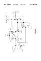
- FIG. 4 is one embodiment of a level shift circuit that is used in a battery state monitoring circuit in accordance with the present invention and a battery pack using the same.
- FIG. 5 is a timing chart of one embodiment of the battery state monitoring circuit in accordance with the present invention and a battery pack using same.
- FIG. 1 shows a battery state monitoring circuit to which the present invention is applied, and a structural example of a battery pack using the same.
- an embodiment of the present invention will be described with reference to FIG. 1 .
- the battery pack 121 is designed such that a plurality of secondary batteries (for example, cells of a lithium ion battery) are connected in series.
- secondary batteries for example, cells of a lithium ion battery
- four secondary batteries 6 , 7 , 8 and 9 are connected in series.
- a negative pole of the secondary battery 9 is connected to a sense resistor 10 .
- the sense resistor 10 is connected to minus terminal 101 or the battery pack 121 .
- a positive pole of the secondary battery 6 is connected to a switch element 12 made up of an FET and the like.
- the switch element 12 and a switch element 11 are connected in series, and the switch element 11 is connected in series to a plus terminal 100 of the battery pack 121 .
- the switch elements 11 and 12 are used as switch elements for controlling discharge from the battery pack 121 and the charging to the battery pack from a charger.
- the switch element 11 When charging of the battery pack 121 is inhibited, the switch element 11 may be turned off. Also, when discharge from the battery pack is inhibited, the switch element 12 may be turned off.
- the switch elements may alternatively be connected between the negative pole of the secondary battery 9 and a sense resistor 10 . In this case, it is necessary that the type of FETs, etc., is appropriately changed according to the structure. Likewise, the sense resistor 10 may be connected to the plus terminal 100 side of the battery pack 121 .
- a battery state monitoring circuit 18 it is necessary to control consumption current from a microcomputer 4 to an amplifier 3 , etc. Because, the consumption of the current of the secondary battery 6 to 9 per se must be suppressed as much as possible to enable use for a long time period, since a power supply of these circuits is derived from the secondary battery 6 to 9 . To enable use for a long time period, preferably a circuit can suppress the current consumption of the amplifier 3 with a signal from the microcomputer 4 .
- the supply voltage of the microcomputer 4 is applied from a voltage regulator 1 .
- the voltage regulator 1 is provided to maintain the output voltage constant even when the supply voltage changes.
- the power supply of the voltage regulator 1 is supplied from a VCC terminal 102 connected to the total voltage of the secondary batteries 6 to 9 connected is series.
- the output voltage of the voltage regulator 1 also lowers.
- a voltage detecting circuit 2 is provided to prevent runaway of the microcomputer 4 when the supply voltage of the microcomputer 4 becomes low.
- the voltage detecting circuit consists of, for example, a comparator 104 and an a reference voltage 105 , and output voltage thereof changes when an input voltage becomes a certain set voltage.
- FIG. 1 when the output voltage of the voltage regulator 1 lowers, the output of the voltage detecting circuit 2 changes.
- the microcomputer 4 can prevent malfunctions in advance by suspending its calculating function when this output change takes place. Generally, such control method is called “reset”. At this time, the supply of power is useless because the microcomputer 4 is not functioning.
- a circuit is required in which voltage regulator 1 does not consume the current to suppress the overall consumption current and also to suppress the charge consumption of the secondary battery.
- the secondary batteries 6 to 9 , the switch elements 11 , 12 , and a sense register 10 are also connected to the battery state monitoring circuit 18 , respectively.
- the battery state monitoring circuit 18 is made up of the microcomputer 4 , a battery voltage monitoring circuit 20 , the amplifier 3 , the voltage regulator 1 , and the voltage detecting circuit 2 .
- the power supply of the battery voltage monitoring circuit 20 , the voltage detecting circuit 2 , etc., is applied from the voltage regulator 1 .
- the power supply of the voltage regulator 1 , the amplifier 3 , etc. is applied the voltage from the VCC terminal 103 .
- the battery voltage monitoring circuit 20 is a circuit consisting of, for example, a multiplexer and an amplifier, which transforms the respective voltages of the secondary batteries 6 to 9 to voltages readable by the microcomputer 4 and applies them to an A/D port 106 .
- the battery voltage monitoring circuit 20 is formed of a circuit in which the respective voltages of the secondary batteries 6 to 9 are sequentially output to one signal line.
- the power supply of the battery voltage monitoring circuit 20 is applied from the voltage regulator 1 .
- the circuit is arranged in such a manner that even if the voltage of the secondary battery 6 to 9 is low, the battery voltage monitoring circuit 20 normally operates immediately after the charger 17 is connected to the battery pack 121 .
- the amplifier 3 is designed to adjust a voltage drop occurring in the sense resistor 10 to a level readable by the microcomputer 4 . Since the resistance value of the sense resistor 10 is generally small to the degree of several tens of m ⁇ , the amplifier 3 amplifies the voltage between the sense resistor 10 terminals and supplies the amplified voltage to the A/D port 107 of the microcomputer 4 .
- the microcomputer 4 has A/D conversion and calculation functions, etc., and also communicates with the outside of the battery pack 121 .
- the AD port 106 and 107 of the microcomputer 4 are supplied with signals from the amplifier 3 and the battery voltage monitoring circuit 20 .
- the microcomputer 4 controls on/off operation of the switch elements 11 and 12 in accordance with the voltage of the secondary battery 6 to 9 .
- the charge/discharge current of the secondary battery 6 to 9 can be calculated by monitoring the voltage drop across the sense resistor 10 . Since the charge/discharge current can be calculated, the capacity of the battery pack 121 can be found.
- the battery state monitoring circuit 18 since the power supply is formed of the secondary battery, it is necessary to suppress the consumption current as much as possible to elongate the operation time. It is an effective method to shut out of the current of unnecessary circuits in accordance with the decision of the microcomputer 4 to suppress the consumption current, while obtaining secondary battery information by operating necessary functions. For example, when the microcomputer 4 monitors the secondary battery voltage, the charge/discharge current can not be monitored, so that the amplifier 3 need not be operated.
- the signal from the microcomputer 4 is input to the amplifier 3 . Since the supply voltage of the microcomputer 4 is applied from the voltage regulator 1 , the voltage of the signal outputted from the microcomputer 4 is equal to the output voltage of the voltage regulator 1 . In order to obtain a circuit structure such that the amplifier 3 suppresses the consumption current with the signal of the microcomputer 4 , a control circuit 51 that converts the low voltage signal of the microcomputer 5 to the VCC terminal 103 voltage must be provided. The power supply of the control circuit 51 is the VCC terminal 103 voltage.
- FIG. 4 An embodiment of the control circuit 51 is shown in FIG. 4 .
- An input terminal 110 is shown by Vin, and an output terminal 111 is shown by Vout.
- the supply voltage of the transistors 56 to 59 are lower than the supply voltage of the transistors 60 to 63 .
- the En terminal 112 voltage (the gate voltage of the transistor 64 ) is used to explain the operation of the circuit as a GND potential. In the case where this circuit is employed, large voltage amplification can be obtained from the output even if low voltage amplification is inputted, so that a logic circuit is readily designed in the case where there are two power supplies.
- the output voltage amplification of the control circuit 51 becomes equal to the VCC terminal 103 voltage.
- the VCC terminal 103 voltage (high supply voltage) and the output of the voltage regulator 1 (low supply voltage) are used for the supply voltage of the control circuit 51 .
- the signal is inputted from the microcomputer 4 to the control circuit 51 , and the output of the control circuit 51 is connected to the amplifier 3 and the voltage regulator 1 .
- the En terminal 112 is inputted signals of the voltage detecting circuit 2 via an inverter 52 .
- the axis of abscissas represents a time
- the axis of ordinates represents a voltage
- the VCC terminal 103 voltage and the supply voltage of the microcomputer 4 are shown.
- a current is supplied to a load from a battery pack, and the VCC terminal 103 voltage drops as time elapses.
- the VCC terminal 103 voltage becomes equal to the output voltage of the voltage regulator 1 .
- the control from the microcomputer 4 to the amplifier 3 is conducted with no problem. It is because the supply voltage of the control circuit 51 is ensured.
- the output voltage of the voltage regulator 1 reaches the detection voltage of the voltage detecting circuit 2 .
- the voltage detecting circuit 2 operates to reset the microcomputer 4 .
- the microcomputer 4 since the microcomputer 4 has already suspended the function, it is unnecessary to supply the power supply.
- the output voltage of the voltage regulator 1 becomes the GND potential.
- the output of the control circuit 51 is prevented from being unstable.
- the output of the control circuit 51 is the voltage to be applied to the En terminal 112 , in the case of FIG.
- the output from the voltage detecting circuit 2 is a signal inputted via the inverter 52 .
- the output of the control circuit 51 is stable, and even if the supply voltage of the microcomputer 4 is not inputted, the current consumption of the amplifier 3 and the voltage regulator 1 can be suppressed.
- the VCC terminal 103 voltage lowers due to the self-discharging of the secondary battery 6 to 9 .
- the current supply from the battery pack 121 to the load is suspended and the charger is connected.
- the secondary battery 6 to 9 is charged and the voltage of the charger 17 becomes higher than the output voltage set at the voltage regulator 1 .
- FIG. 3 shows another embodiment.
- the output voltage control of the voltage regulator 1 a is enabled from outside of the battery state monitoring circuit 181 .
- the output voltage of the control circuit 51 is stable even though the low supply voltage of the control circuit 51 is shut out unexpectedly and the current consumption function of the amplifier 3 operates normally. The present invention is effective even if the voltage regulator 1 a is thus controlled from the outside.
- the microcomputer 4 and the battery state monitoring circuit 18 are structured as different parts.
- the structural elements and the operation principles are entirely identical with those in the embodiment described with reference to FIG. 1 .
- the battery pack according to the present invention is effective even if all of functions are provided in one part (IC), and the same effect is obtained even if a plurality of parts are provided by mounting the microcomputer 4 , the switch elements 11 , 12 , etc., on a substrate.
- the control signal of the internal circuit is maintained stable even in the case where the voltage of the regulator is not outputted, the safety of the battery pack is enhanced such that the control to the respective blocks can be conducted from the microcomputer with the signal in the case where the output voltage of the regulator is normal, and the battery state is monitored for a long time period by suppressing charge consumption of the battery. For this, the battery state monitoring is accurately conducted, thereby obtaining information high in quality from the battery pack.
Abstract
Description
Claims (11)
Applications Claiming Priority (2)
| Application Number | Priority Date | Filing Date | Title |
|---|---|---|---|
| JP10-143394 | 1998-05-25 | ||
| JP10143394A JPH11341689A (en) | 1998-05-25 | 1998-05-25 | Battery performance monitoring circuit and battery apparatus |
Publications (1)
| Publication Number | Publication Date |
|---|---|
| US6198252B1 true US6198252B1 (en) | 2001-03-06 |
Family
ID=15337752
Family Applications (1)
| Application Number | Title | Priority Date | Filing Date |
|---|---|---|---|
| US09/317,581 Expired - Lifetime US6198252B1 (en) | 1998-05-25 | 1999-05-24 | Battery state monitoring circuit and battery device |
Country Status (6)
| Country | Link |
|---|---|
| US (1) | US6198252B1 (en) |
| JP (1) | JPH11341689A (en) |
| KR (1) | KR19990088544A (en) |
| CN (1) | CN1187859C (en) |
| HK (1) | HK1023654A1 (en) |
| TW (1) | TW431046B (en) |
Cited By (17)
| Publication number | Priority date | Publication date | Assignee | Title |
|---|---|---|---|---|
| US20030099075A1 (en) * | 2001-11-29 | 2003-05-29 | Dialog Semiconductor Gmbh | Charge/discharge protection circuit |
| CN1295811C (en) * | 2004-08-11 | 2007-01-17 | 北京中信国安盟固利新材料技术研究院有限公司 | Lithium ion cell energy pack for electric bicycle |
| US20070075684A1 (en) * | 2005-10-04 | 2007-04-05 | Shiqiang Liu | Battery charge/discharge control circuit |
| US20070075682A1 (en) * | 2005-09-30 | 2007-04-05 | Guang Huang T | Rapid charge lithium ion battery charger |
| US20070132457A1 (en) * | 2005-12-12 | 2007-06-14 | Yazaki Corporation | Voltage detector and insulator interface |
| US20070236173A1 (en) * | 2006-04-06 | 2007-10-11 | Tadao Kimura | Battery pack and electric device using the same |
| US20080238368A1 (en) * | 2007-03-27 | 2008-10-02 | Honeywell International Inc. | Voltage regulator in a battery cell |
| US20080252257A1 (en) * | 2005-04-05 | 2008-10-16 | Energy Control Systems Engineering, Inc. D/B/A Energycs | Multiplexer and Switch-Based Electrochemical Cell Monitor and Management System and Method |
| US20090174410A1 (en) * | 2006-05-04 | 2009-07-09 | Lg Chem, Ltd. | Method and apparatus for controlling battery |
| US20090179617A1 (en) * | 2007-12-06 | 2009-07-16 | Toshiyuki Koike | Battery state monitoring circuit and battery device |
| US20090261786A1 (en) * | 2008-04-16 | 2009-10-22 | Texas Instruments Incorporated | Battery charge compensation |
| US20100060237A1 (en) * | 2008-09-05 | 2010-03-11 | Fih (Hong Kong) Limited | Battery discharge circuit and discharge method thereof |
| US20110298429A1 (en) * | 2010-06-04 | 2011-12-08 | Po-Han Chiu | Power path management circuit and method |
| US20120032639A1 (en) * | 2010-08-06 | 2012-02-09 | Samsung Sdi Co., Ltd. | Battery pack, charger, and charging system |
| US20120169295A1 (en) * | 2007-06-20 | 2012-07-05 | Li Peter T | Battery pulse charging method and apparatus |
| US20120319483A1 (en) * | 2011-06-20 | 2012-12-20 | Scruggs Michael K | Apparatus for bi-directional power switching in low voltage vehicle power distribution systems |
| US20140167702A1 (en) * | 2012-12-17 | 2014-06-19 | Seiko Instruments Inc. | Charging and discharging control circuit and battery device |
Families Citing this family (9)
| Publication number | Priority date | Publication date | Assignee | Title |
|---|---|---|---|---|
| JP4555502B2 (en) * | 2001-04-24 | 2010-10-06 | セイコーインスツル株式会社 | Battery state monitoring circuit and battery device |
| JP4135366B2 (en) * | 2002-01-25 | 2008-08-20 | 三菱マテリアル株式会社 | Secondary battery |
| CN100370270C (en) * | 2003-06-24 | 2008-02-20 | 明基电通股份有限公司 | Voltage detecting method and related circuit |
| JP2006244788A (en) * | 2005-03-01 | 2006-09-14 | Sanyo Electric Co Ltd | Discharge method of battery and battery pack |
| KR101156400B1 (en) * | 2006-03-27 | 2012-06-13 | 삼성에스디아이 주식회사 | Battery pack |
| JP2009159811A (en) * | 2007-12-06 | 2009-07-16 | Seiko Instruments Inc | Battery condition monitoring circuit and battery device |
| CN101267122A (en) * | 2008-01-02 | 2008-09-17 | 何岳明 | Charging and discharging protection circuit for multiple serial lithium battery |
| JP5742593B2 (en) * | 2011-08-30 | 2015-07-01 | ミツミ電機株式会社 | Semiconductor integrated circuit, protection circuit and battery pack |
| US11811036B1 (en) * | 2022-10-14 | 2023-11-07 | Beta Air, Llc | Apparatus and method for fault detection in a battery module |
Citations (3)
| Publication number | Priority date | Publication date | Assignee | Title |
|---|---|---|---|---|
| US5764028A (en) * | 1995-12-15 | 1998-06-09 | Compaq Computer Corporation | Battery pack with single charge-inhibit/regulator transistor |
| US5796238A (en) * | 1992-10-13 | 1998-08-18 | Sony Corporation | Battery pack |
| US5890780A (en) * | 1996-10-07 | 1999-04-06 | Nec Corporation | Power supply switching apparatus with protection function for supplying power to an electronic circuit via an external power source or an internal power supply source |
-
1998
- 1998-05-25 JP JP10143394A patent/JPH11341689A/en active Pending
-
1999
- 1999-05-24 US US09/317,581 patent/US6198252B1/en not_active Expired - Lifetime
- 1999-05-24 TW TW088108470A patent/TW431046B/en not_active IP Right Cessation
- 1999-05-25 KR KR19990018894A patent/KR19990088544A/en not_active Application Discontinuation
- 1999-05-25 CN CNB991092503A patent/CN1187859C/en not_active Expired - Lifetime
-
2000
- 2000-05-05 HK HK00102737A patent/HK1023654A1/en not_active IP Right Cessation
Patent Citations (3)
| Publication number | Priority date | Publication date | Assignee | Title |
|---|---|---|---|---|
| US5796238A (en) * | 1992-10-13 | 1998-08-18 | Sony Corporation | Battery pack |
| US5764028A (en) * | 1995-12-15 | 1998-06-09 | Compaq Computer Corporation | Battery pack with single charge-inhibit/regulator transistor |
| US5890780A (en) * | 1996-10-07 | 1999-04-06 | Nec Corporation | Power supply switching apparatus with protection function for supplying power to an electronic circuit via an external power source or an internal power supply source |
Cited By (38)
| Publication number | Priority date | Publication date | Assignee | Title |
|---|---|---|---|---|
| US6791809B2 (en) * | 2001-11-29 | 2004-09-14 | Dialog Semiconductor Gmbh | Charge/discharge protection circuit |
| US20030099075A1 (en) * | 2001-11-29 | 2003-05-29 | Dialog Semiconductor Gmbh | Charge/discharge protection circuit |
| CN1295811C (en) * | 2004-08-11 | 2007-01-17 | 北京中信国安盟固利新材料技术研究院有限公司 | Lithium ion cell energy pack for electric bicycle |
| US20080252257A1 (en) * | 2005-04-05 | 2008-10-16 | Energy Control Systems Engineering, Inc. D/B/A Energycs | Multiplexer and Switch-Based Electrochemical Cell Monitor and Management System and Method |
| US20130119935A1 (en) * | 2005-04-05 | 2013-05-16 | Daniel A. Sufrin-Disler | Multiplexer and switch-based electrochemical cell monitor and management system and method |
| US7626362B2 (en) | 2005-09-30 | 2009-12-01 | International Components Corporation | Rapid charge lithium ion battery charger |
| WO2007040948A2 (en) * | 2005-09-30 | 2007-04-12 | International Components Corporation | Rapid charge lithium ion battery charger |
| US20070075682A1 (en) * | 2005-09-30 | 2007-04-05 | Guang Huang T | Rapid charge lithium ion battery charger |
| US20080012533A1 (en) * | 2005-09-30 | 2008-01-17 | Guang Huang T | Rapid charge lithium ion battery charger |
| US20080024090A1 (en) * | 2005-09-30 | 2008-01-31 | Guang Huang T | Rapid charge lithium ion battery charger |
| US7683574B2 (en) * | 2005-09-30 | 2010-03-23 | International Components Corporation | Rapid charge lithium ion battery charger |
| US7598709B2 (en) | 2005-09-30 | 2009-10-06 | International Components Corporation | Rapid charge lithium ion battery charger |
| US20100033137A1 (en) * | 2005-09-30 | 2010-02-11 | Huang Tai Guang | Rapid charge lithium ion battery charger |
| WO2007040948A3 (en) * | 2005-09-30 | 2009-04-23 | Internat Components Corp | Rapid charge lithium ion battery charger |
| US7898220B2 (en) | 2005-09-30 | 2011-03-01 | Icc-Nexergy, Inc. | Rapid charge lithium ion battery charger |
| US20070075684A1 (en) * | 2005-10-04 | 2007-04-05 | Shiqiang Liu | Battery charge/discharge control circuit |
| US7642750B2 (en) * | 2005-10-04 | 2010-01-05 | O2Micro International Limited | Battery charge/discharge control circuit |
| US20070132457A1 (en) * | 2005-12-12 | 2007-06-14 | Yazaki Corporation | Voltage detector and insulator interface |
| US7405579B2 (en) * | 2005-12-12 | 2008-07-29 | Yazaki Corporation | Voltage detector and insulator interface |
| US20070236173A1 (en) * | 2006-04-06 | 2007-10-11 | Tadao Kimura | Battery pack and electric device using the same |
| US7663339B2 (en) | 2006-04-06 | 2010-02-16 | Panasonic Corporation | Battery pack having a communicator for communicating with electric device and electric device using the same |
| US20090174410A1 (en) * | 2006-05-04 | 2009-07-09 | Lg Chem, Ltd. | Method and apparatus for controlling battery |
| US8400116B2 (en) | 2006-05-04 | 2013-03-19 | Lg Chem, Ltd. | Method and apparatus for calculating power-off duration time and state of charging of battery |
| US20080238368A1 (en) * | 2007-03-27 | 2008-10-02 | Honeywell International Inc. | Voltage regulator in a battery cell |
| US7633261B2 (en) | 2007-03-27 | 2009-12-15 | Honeywell International Inc. | Primary battery with internal voltage regulator |
| US9502918B2 (en) | 2007-06-20 | 2016-11-22 | Intel Corporation | Battery pulse charging method and apparatus |
| US20120169295A1 (en) * | 2007-06-20 | 2012-07-05 | Li Peter T | Battery pulse charging method and apparatus |
| US8917063B2 (en) * | 2007-06-20 | 2014-12-23 | Intel Corporation | Battery pulse charging method and apparatus |
| US20090179617A1 (en) * | 2007-12-06 | 2009-07-16 | Toshiyuki Koike | Battery state monitoring circuit and battery device |
| US20090261786A1 (en) * | 2008-04-16 | 2009-10-22 | Texas Instruments Incorporated | Battery charge compensation |
| US8421416B2 (en) * | 2008-04-16 | 2013-04-16 | Texas Instruments Incorporated | Battery charge compensation |
| US20100060237A1 (en) * | 2008-09-05 | 2010-03-11 | Fih (Hong Kong) Limited | Battery discharge circuit and discharge method thereof |
| US20110298429A1 (en) * | 2010-06-04 | 2011-12-08 | Po-Han Chiu | Power path management circuit and method |
| US8723479B2 (en) * | 2010-08-06 | 2014-05-13 | Samsung Sdi Co., Ltd. | Battery pack, charger, and charging system that protects rechargeable batteries against a malfunctioning protection circuit |
| US20120032639A1 (en) * | 2010-08-06 | 2012-02-09 | Samsung Sdi Co., Ltd. | Battery pack, charger, and charging system |
| US20120319483A1 (en) * | 2011-06-20 | 2012-12-20 | Scruggs Michael K | Apparatus for bi-directional power switching in low voltage vehicle power distribution systems |
| US8941264B2 (en) * | 2011-06-20 | 2015-01-27 | Bae Systems Information And Electronic Systems Integration Inc. | Apparatus for bi-directional power switching in low voltage vehicle power distribution systems |
| US20140167702A1 (en) * | 2012-12-17 | 2014-06-19 | Seiko Instruments Inc. | Charging and discharging control circuit and battery device |
Also Published As
| Publication number | Publication date |
|---|---|
| CN1187859C (en) | 2005-02-02 |
| JPH11341689A (en) | 1999-12-10 |
| TW431046B (en) | 2001-04-21 |
| HK1023654A1 (en) | 2000-09-15 |
| KR19990088544A (en) | 1999-12-27 |
| CN1239335A (en) | 1999-12-22 |
Similar Documents
| Publication | Publication Date | Title |
|---|---|---|
| US6198252B1 (en) | Battery state monitoring circuit and battery device | |
| US6489749B1 (en) | Battery state monitoring circuit having differentiating circuit | |
| US6265848B1 (en) | Battery state monitoring circuit and battery device | |
| EP0480648B1 (en) | NI-Cad battery charge rate controller | |
| TWI418109B (en) | Battery apparatus, integrated circuit for battery system and battery protection method | |
| US7830121B2 (en) | Battery pack | |
| US8581552B2 (en) | Battery state monitoring circuitry with low power consumption during a stand-by-state of a battery pack | |
| US8957638B2 (en) | Battery control circuit responsive to external signal input | |
| JP3905005B2 (en) | Portable device and semiconductor integrated circuit device | |
| KR100562877B1 (en) | Charging and discharging control circuit and charging type power supply device | |
| US7791315B2 (en) | Battery state monitoring circuit and battery device | |
| US9929590B2 (en) | Dual input RTC supply generation with replica power path and autonomous mode of operation from the system supply | |
| US20070013342A1 (en) | Battery pack | |
| KR20080011088A (en) | Constant voltage supply circuit | |
| US6060863A (en) | Charge and discharge control circuit and chargeable power supply unit | |
| KR100584324B1 (en) | Apparatus for controlling power in complex mobile terminal | |
| KR100328888B1 (en) | Charge and discharge control circuit | |
| US7701178B2 (en) | Charge control that keeps constant input voltage supplied to battery pack | |
| US6218810B1 (en) | Output circuit and battery pack | |
| JPH1012283A (en) | Battery pack and its control method | |
| KR100228518B1 (en) | Charging and discharging control circuit | |
| KR100352399B1 (en) | Charge/discharge control circuit and chargeable electric power source apparatus | |
| JP4598947B2 (en) | Differential amplifier | |
| KR20220153500A (en) | Secondary battery protection circuit, battery pack, battery system and method for protecting secondary battery | |
| KR19990083345A (en) | Battery state monitoring circuit and battery device |
Legal Events
| Date | Code | Title | Description |
|---|---|---|---|
| AS | Assignment |
Owner name: SEIKO INSTRUMENTS INC., JAPAN Free format text: ASSIGNMENT OF ASSIGNORS INTEREST;ASSIGNOR:MUKAINAKANO, HIROSHI;REEL/FRAME:011375/0570 Effective date: 20001206 |
|
| STCF | Information on status: patent grant |
Free format text: PATENTED CASE |
|
| FPAY | Fee payment |
Year of fee payment: 4 |
|
| FPAY | Fee payment |
Year of fee payment: 8 |
|
| FPAY | Fee payment |
Year of fee payment: 12 |
|
| AS | Assignment |
Owner name: SII SEMICONDUCTOR CORPORATION, JAPAN Free format text: ASSIGNMENT OF ASSIGNORS INTEREST;ASSIGNOR:SEIKO INSTRUMENTS INC.;REEL/FRAME:038058/0892 Effective date: 20160105 |
|
| AS | Assignment |
Owner name: ABLIC INC., JAPAN Free format text: CHANGE OF NAME;ASSIGNOR:SII SEMICONDUCTOR CORPORATION;REEL/FRAME:045567/0927 Effective date: 20180105 |