US6200160B1 - Protective console unit for electrical or optical connectors - Google Patents
Protective console unit for electrical or optical connectors Download PDFInfo
- Publication number
- US6200160B1 US6200160B1 US09/299,169 US29916999A US6200160B1 US 6200160 B1 US6200160 B1 US 6200160B1 US 29916999 A US29916999 A US 29916999A US 6200160 B1 US6200160 B1 US 6200160B1
- Authority
- US
- United States
- Prior art keywords
- connector
- wall
- base
- mounting portion
- faceplate
- Prior art date
- Legal status (The legal status is an assumption and is not a legal conclusion. Google has not performed a legal analysis and makes no representation as to the accuracy of the status listed.)
- Expired - Fee Related
Links
Images


Classifications
-
- G—PHYSICS
- G02—OPTICS
- G02B—OPTICAL ELEMENTS, SYSTEMS OR APPARATUS
- G02B6/00—Light guides; Structural details of arrangements comprising light guides and other optical elements, e.g. couplings
- G02B6/24—Coupling light guides
- G02B6/36—Mechanical coupling means
- G02B6/38—Mechanical coupling means having fibre to fibre mating means
- G02B6/3807—Dismountable connectors, i.e. comprising plugs
- G02B6/3897—Connectors fixed to housings, casing, frames or circuit boards
-
- H—ELECTRICITY
- H01—ELECTRIC ELEMENTS
- H01R—ELECTRICALLY-CONDUCTIVE CONNECTIONS; STRUCTURAL ASSOCIATIONS OF A PLURALITY OF MUTUALLY-INSULATED ELECTRICAL CONNECTING ELEMENTS; COUPLING DEVICES; CURRENT COLLECTORS
- H01R13/00—Details of coupling devices of the kinds covered by groups H01R12/70 or H01R24/00 - H01R33/00
- H01R13/62—Means for facilitating engagement or disengagement of coupling parts or for holding them in engagement
- H01R13/639—Additional means for holding or locking coupling parts together, after engagement, e.g. separate keylock, retainer strap
- H01R13/6395—Additional means for holding or locking coupling parts together, after engagement, e.g. separate keylock, retainer strap for wall or panel outlets
-
- H—ELECTRICITY
- H02—GENERATION; CONVERSION OR DISTRIBUTION OF ELECTRIC POWER
- H02G—INSTALLATION OF ELECTRIC CABLES OR LINES, OR OF COMBINED OPTICAL AND ELECTRIC CABLES OR LINES
- H02G3/00—Installations of electric cables or lines or protective tubing therefor in or on buildings, equivalent structures or vehicles
- H02G3/02—Details
- H02G3/08—Distribution boxes; Connection or junction boxes
- H02G3/14—Fastening of cover or lid to box
Definitions
- the connector mounting portion may be generally recessed to define an acute angle with respect to a surrounding region of the base surface, so that a connector supported in an opening in the mounting portion is accessible for connection to a mating connector aligned at the front side of the base surface at a corresponding angle with respect to the base surface.
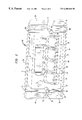
- FIG. 4 is a perspective view of the console unit mounted vertically on part of a cable raceway wall, as seen from behind the unit.
- the console unit 10 can be injection molded as a unitary, integral body from dielectric insulative materials such as, for example, a blend of polycarbonate and ABS.
- dielectric insulative materials such as, for example, a blend of polycarbonate and ABS.
- the material of which the unit 10 is formed should meet all applicable standards with respect to electrical insulation resistance and flammability, in view of the environment in which the unit is to be used.
- Each of the connector openings is formed and sized to mount a typical connector; for example, series MPS100E or series MGS200 modular communication jack connectors available from Lucent Technologies Inc.
- Other connectors whose mounting requirements can be accommodated by forming corresponding connector positions or openings in the connector mounting portion 16 , may also be used.
- the protective wall 26 also forms a top wall 50 that is joined to the base wall 14 and to the two side walls 30 , 40 .
- the top wall 50 extends generally perpendicular to the base wall 14 and to the two side walls 30 , 40 .
- the top wall 50 has an upper edge 52 that coincides with the upper edges 32 , 42 of the side walls 30 , 40 , so that the upper edge 52 is also at the height H above the base wall 14 .
- a pair of mounting holes 60 , 62 are formed through the base wall 14 for receiving and guiding mounting screws or other fasteners to secure the unit 10 on the wall 12 , or to some other mounting surface. See FIGS. 1 and 2.
- FIG. 2 is a view of the unit 10 as seen from behind the unit.
- the protective hood or wall 26 and a lower front panel 64 together form a generally rectangular bottom edge 70 .
- the bottom edge 70 is dimensioned and arranged to seat flush with a mounting surface (e.g., the wall 12 ) on which the unit 10 will be mounted.
Landscapes
- Physics & Mathematics (AREA)
- General Physics & Mathematics (AREA)
- Optics & Photonics (AREA)
- Connector Housings Or Holding Contact Members (AREA)
Abstract
Description
Claims (12)
Priority Applications (1)
| Application Number | Priority Date | Filing Date | Title |
|---|---|---|---|
| US09/299,169 US6200160B1 (en) | 1999-04-26 | 1999-04-26 | Protective console unit for electrical or optical connectors |
Applications Claiming Priority (1)
| Application Number | Priority Date | Filing Date | Title |
|---|---|---|---|
| US09/299,169 US6200160B1 (en) | 1999-04-26 | 1999-04-26 | Protective console unit for electrical or optical connectors |
Publications (1)
| Publication Number | Publication Date |
|---|---|
| US6200160B1 true US6200160B1 (en) | 2001-03-13 |
Family
ID=23153590
Family Applications (1)
| Application Number | Title | Priority Date | Filing Date |
|---|---|---|---|
| US09/299,169 Expired - Fee Related US6200160B1 (en) | 1999-04-26 | 1999-04-26 | Protective console unit for electrical or optical connectors |
Country Status (1)
| Country | Link |
|---|---|
| US (1) | US6200160B1 (en) |
Cited By (10)
| Publication number | Priority date | Publication date | Assignee | Title |
|---|---|---|---|---|
| US6422898B1 (en) * | 2000-08-31 | 2002-07-23 | Corning Cable Systems Llc | Retaining hook assembly for outlet cover |
| US6435727B1 (en) * | 1999-02-05 | 2002-08-20 | Fiber Connections, Inc. | Connector for fiber optic cable |
| US20060019533A1 (en) * | 2004-07-23 | 2006-01-26 | Yuan-Huei Peng | Bezel of modular jack |
| WO2007096922A1 (en) * | 2006-02-27 | 2007-08-30 | Bticino S.P.A. | Device for protecting electrical apparatus and a group of parts including said device |
| WO2008088035A1 (en) * | 2007-01-19 | 2008-07-24 | Sumitomo Electric Industries, Ltd. | Outlet device |
| US20100140246A1 (en) * | 2008-12-08 | 2010-06-10 | Ford Global Technologies, Llc | System and method for controlling heating in a hybrid vehicle using a power source external to the hybrid vehicle |
| US20100140244A1 (en) * | 2008-12-08 | 2010-06-10 | Ford Global Technologies, Llc | Integrated side view mirror assembly and electrical port for an automotive vehicle |
| US20150131213A1 (en) * | 2013-10-31 | 2015-05-14 | Airbus Operations Gmbh | Display device for an aircraft |
| US20150229083A1 (en) * | 2014-02-10 | 2015-08-13 | Erbe Elektromedizin Gmbh | Socket Insert For An Electrosurgical Device, Electrosurgical Device With A Socket Insert And Set With A Removal Tool |
| US11374357B2 (en) * | 2019-11-11 | 2022-06-28 | Neutrik Ag | Chassis connector |
Citations (9)
| Publication number | Priority date | Publication date | Assignee | Title |
|---|---|---|---|---|
| US3813640A (en) | 1972-05-08 | 1974-05-28 | Hubbell Inc Harvey | Weatherproof enclosure for electrical devices |
| US4603931A (en) * | 1984-12-14 | 1986-08-05 | Ruffman Samuel H | Anti-theft device for appliances with electrical AC power cords |
| US5096439A (en) | 1991-08-28 | 1992-03-17 | At&T Bell Laboratories | Wall plate having jack-release slots |
| US5302140A (en) | 1993-04-02 | 1994-04-12 | At&T Bell Laboratories | Connector with mounting collar for use in universal patch panel systems |
| US5362254A (en) | 1992-12-18 | 1994-11-08 | The Siemon Company | Electrically balanced connector assembly |
| US5419721A (en) | 1993-04-05 | 1995-05-30 | Societe Anonyme Dite: Eurocopter France | Electrical connector provided with a plurality of connection modules arranged in rows and columns |
| US5897395A (en) * | 1997-05-30 | 1999-04-27 | Lucent Technologies Inc. | Multi-position jack frame |
| US5899761A (en) * | 1997-09-11 | 1999-05-04 | Fiskars Inc. | Power strip |
| US6051786A (en) * | 1995-03-24 | 2000-04-18 | Arlington Industries, Inc. | Siding box |
-
1999
- 1999-04-26 US US09/299,169 patent/US6200160B1/en not_active Expired - Fee Related
Patent Citations (9)
| Publication number | Priority date | Publication date | Assignee | Title |
|---|---|---|---|---|
| US3813640A (en) | 1972-05-08 | 1974-05-28 | Hubbell Inc Harvey | Weatherproof enclosure for electrical devices |
| US4603931A (en) * | 1984-12-14 | 1986-08-05 | Ruffman Samuel H | Anti-theft device for appliances with electrical AC power cords |
| US5096439A (en) | 1991-08-28 | 1992-03-17 | At&T Bell Laboratories | Wall plate having jack-release slots |
| US5362254A (en) | 1992-12-18 | 1994-11-08 | The Siemon Company | Electrically balanced connector assembly |
| US5302140A (en) | 1993-04-02 | 1994-04-12 | At&T Bell Laboratories | Connector with mounting collar for use in universal patch panel systems |
| US5419721A (en) | 1993-04-05 | 1995-05-30 | Societe Anonyme Dite: Eurocopter France | Electrical connector provided with a plurality of connection modules arranged in rows and columns |
| US6051786A (en) * | 1995-03-24 | 2000-04-18 | Arlington Industries, Inc. | Siding box |
| US5897395A (en) * | 1997-05-30 | 1999-04-27 | Lucent Technologies Inc. | Multi-position jack frame |
| US5899761A (en) * | 1997-09-11 | 1999-05-04 | Fiskars Inc. | Power strip |
Non-Patent Citations (2)
| Title |
|---|
| Lucent Technologies Inc., on-line catalog SYSTIMAX Series MGS200 Series GigaSPEED Information Outlet Product Review Sheets, 2 pages. |
| Lucent Technologies Inc., on-line catalog SYSTIMAX Series MPS 100E Modular Information Outlet Product Review sheets, 2 pages. |
Cited By (17)
| Publication number | Priority date | Publication date | Assignee | Title |
|---|---|---|---|---|
| US6435727B1 (en) * | 1999-02-05 | 2002-08-20 | Fiber Connections, Inc. | Connector for fiber optic cable |
| US6422898B1 (en) * | 2000-08-31 | 2002-07-23 | Corning Cable Systems Llc | Retaining hook assembly for outlet cover |
| US20060019533A1 (en) * | 2004-07-23 | 2006-01-26 | Yuan-Huei Peng | Bezel of modular jack |
| US7131864B2 (en) * | 2004-07-23 | 2006-11-07 | Yuan-Huei Peng | Bezel of modular jack |
| CN101375476B (en) * | 2006-02-27 | 2011-07-20 | 布蒂克诺公司 | Device for protecting electrical apparatus and a group of parts including said device |
| WO2007096922A1 (en) * | 2006-02-27 | 2007-08-30 | Bticino S.P.A. | Device for protecting electrical apparatus and a group of parts including said device |
| US20090084573A1 (en) * | 2006-02-27 | 2009-04-02 | Bticino S.P.A. | Device for protecting electrical apparatus and a group of parts including said device |
| EA013458B1 (en) * | 2006-02-27 | 2010-04-30 | Бтичино С.П.А. | Device for protecting electrical apparatus and a group of parts including said device |
| WO2008088035A1 (en) * | 2007-01-19 | 2008-07-24 | Sumitomo Electric Industries, Ltd. | Outlet device |
| US20100140246A1 (en) * | 2008-12-08 | 2010-06-10 | Ford Global Technologies, Llc | System and method for controlling heating in a hybrid vehicle using a power source external to the hybrid vehicle |
| US20100140244A1 (en) * | 2008-12-08 | 2010-06-10 | Ford Global Technologies, Llc | Integrated side view mirror assembly and electrical port for an automotive vehicle |
| US10279684B2 (en) | 2008-12-08 | 2019-05-07 | Ford Global Technologies, Llc | System and method for controlling heating in a hybrid vehicle using a power source external to the hybrid vehicle |
| US20150131213A1 (en) * | 2013-10-31 | 2015-05-14 | Airbus Operations Gmbh | Display device for an aircraft |
| US9668364B2 (en) * | 2013-10-31 | 2017-05-30 | Airbus Operations Gmbh | Display device for an aircraft |
| US20150229083A1 (en) * | 2014-02-10 | 2015-08-13 | Erbe Elektromedizin Gmbh | Socket Insert For An Electrosurgical Device, Electrosurgical Device With A Socket Insert And Set With A Removal Tool |
| US9666974B2 (en) * | 2014-02-10 | 2017-05-30 | Erbe Elektromedizin Gmbh | Socket insert for an electrosurgical device, electrosurgical device with a socket insert and set with a removal tool |
| US11374357B2 (en) * | 2019-11-11 | 2022-06-28 | Neutrik Ag | Chassis connector |
Similar Documents
| Publication | Publication Date | Title |
|---|---|---|
| US4792881A (en) | Work surface with power and communication module | |
| US5122069A (en) | Access flooring module | |
| US6307736B1 (en) | Portable computer with vertically positionable keyboard | |
| US5164544A (en) | Electrified space dividing panel | |
| US5790372A (en) | Computer power supply mounting apparatus and method | |
| US7454116B2 (en) | Wall mount chassis | |
| US5804765A (en) | Cable management enclosure | |
| US6200160B1 (en) | Protective console unit for electrical or optical connectors | |
| US6245998B1 (en) | Cable management assembly for equipment racks | |
| US7207835B2 (en) | Angled patch panel assembly | |
| US4964017A (en) | Adaptable housing for embedding of computer-controlled products | |
| US5548489A (en) | Wiring cabinet having vertically aligned patch panels | |
| US5778612A (en) | Partition panel containing data processing or communications equipment | |
| US20020012242A1 (en) | Cable management apparatus and method | |
| US5807139A (en) | Surface mount multimedia outlet | |
| US20020185295A1 (en) | Movable electrical and data services module | |
| US20080181571A1 (en) | Patch Panels With Communications Connectors that are Rotatable About a Vertical Axis | |
| US7142763B2 (en) | Optical waveguide distribution cabinet | |
| US4603229A (en) | Utility module for walls | |
| US5503472A (en) | Method and apparatus for assembly of a multi-disk pack unit | |
| US6270046B1 (en) | Apparatus for mounting a switching power supply in a computer system | |
| CA2604882A1 (en) | Electrical floor access module system | |
| US7563117B2 (en) | Electrical system assembly with mounting bracket | |
| US5789702A (en) | Modular component of appliance housing | |
| US20020008965A1 (en) | Audio rack for a vehicle |
Legal Events
| Date | Code | Title | Description |
|---|---|---|---|
| AS | Assignment |
Owner name: LUCENT TECHNOLOGIES INC., NEW JERSEY Free format text: ASSIGNMENT OF ASSIGNORS INTEREST;ASSIGNORS:DREXLER, LEONARD H.;REED, DAVID L.;REEL/FRAME:009926/0351 Effective date: 19990423 |
|
| AS | Assignment |
Owner name: AVAYA TECHNOLOGY CORP., FLORIDA Free format text: ASSIGNMENT OF ASSIGNORS INTEREST;ASSIGNOR:LUCENT TECHNOLOGIES INC.;REEL/FRAME:011398/0803 Effective date: 20000929 |
|
| AS | Assignment |
Owner name: BANK OF NEW YORK, THE, NEW YORK Free format text: SECURITY AGREEMENT;ASSIGNOR:AVAYA TECHNOLOGY CORP.;REEL/FRAME:012775/0144 Effective date: 20020405 |
|
| FPAY | Fee payment |
Year of fee payment: 4 |
|
| AS | Assignment |
Owner name: AVAYA TECHNOLOGY CORPORATION, NEW JERSEY Free format text: RELEASE BY SECURED PARTY;ASSIGNOR:THE BANK OF NEW YORK;REEL/FRAME:019881/0532 Effective date: 20040101 |
|
| AS | Assignment |
Owner name: COMMSCOPE SOLUTIONS PROPERTIES, LLC, NEVADA Free format text: ASSIGNMENT OF ASSIGNORS INTEREST;ASSIGNOR:AVAYA TECHNOLOGY CORPORATION;REEL/FRAME:019984/0046 Effective date: 20040129 |
|
| AS | Assignment |
Owner name: COMMSCOPE, INC. OF NORTH CAROLINA, NORTH CAROLINA Free format text: MERGER;ASSIGNOR:COMMSCOPE SOLUTIONS PROPERTIES, LLC;REEL/FRAME:019991/0643 Effective date: 20061220 Owner name: COMMSCOPE, INC. OF NORTH CAROLINA,NORTH CAROLINA Free format text: MERGER;ASSIGNOR:COMMSCOPE SOLUTIONS PROPERTIES, LLC;REEL/FRAME:019991/0643 Effective date: 20061220 |
|
| AS | Assignment |
Owner name: BANK OF AMERICA, N.A., AS ADMINISTRATIVE AGENT, CA Free format text: SECURITY AGREEMENT;ASSIGNORS:COMMSCOPE, INC. OF NORTH CAROLINA;ALLEN TELECOM, LLC;ANDREW CORPORATION;REEL/FRAME:020362/0241 Effective date: 20071227 Owner name: BANK OF AMERICA, N.A., AS ADMINISTRATIVE AGENT,CAL Free format text: SECURITY AGREEMENT;ASSIGNORS:COMMSCOPE, INC. OF NORTH CAROLINA;ALLEN TELECOM, LLC;ANDREW CORPORATION;REEL/FRAME:020362/0241 Effective date: 20071227 |
|
| FPAY | Fee payment |
Year of fee payment: 8 |
|
| AS | Assignment |
Owner name: ANDREW LLC (F/K/A ANDREW CORPORATION), NORTH CAROL Free format text: PATENT RELEASE;ASSIGNOR:BANK OF AMERICA, N.A., AS ADMINISTRATIVE AGENT;REEL/FRAME:026039/0005 Effective date: 20110114 Owner name: ALLEN TELECOM LLC, NORTH CAROLINA Free format text: PATENT RELEASE;ASSIGNOR:BANK OF AMERICA, N.A., AS ADMINISTRATIVE AGENT;REEL/FRAME:026039/0005 Effective date: 20110114 Owner name: COMMSCOPE, INC. OF NORTH CAROLINA, NORTH CAROLINA Free format text: PATENT RELEASE;ASSIGNOR:BANK OF AMERICA, N.A., AS ADMINISTRATIVE AGENT;REEL/FRAME:026039/0005 Effective date: 20110114 |
|
| AS | Assignment |
Owner name: JPMORGAN CHASE BANK, N.A., AS COLLATERAL AGENT, NE Free format text: SECURITY AGREEMENT;ASSIGNORS:ALLEN TELECOM LLC, A DELAWARE LLC;ANDREW LLC, A DELAWARE LLC;COMMSCOPE, INC. OF NORTH CAROLINA, A NORTH CAROLINA CORPORATION;REEL/FRAME:026276/0363 Effective date: 20110114 |
|
| AS | Assignment |
Owner name: JPMORGAN CHASE BANK, N.A., AS COLLATERAL AGENT, NE Free format text: SECURITY AGREEMENT;ASSIGNORS:ALLEN TELECOM LLC, A DELAWARE LLC;ANDREW LLC, A DELAWARE LLC;COMMSCOPE, INC OF NORTH CAROLINA, A NORTH CAROLINA CORPORATION;REEL/FRAME:026272/0543 Effective date: 20110114 |
|
| REMI | Maintenance fee reminder mailed | ||
| LAPS | Lapse for failure to pay maintenance fees | ||
| STCH | Information on status: patent discontinuation |
Free format text: PATENT EXPIRED DUE TO NONPAYMENT OF MAINTENANCE FEES UNDER 37 CFR 1.362 |
|
| FP | Lapsed due to failure to pay maintenance fee |
Effective date: 20130313 |
|
| AS | Assignment |
Owner name: AVAYA INC. (FORMERLY KNOWN AS AVAYA TECHNOLOGY COR Free format text: BANKRUPTCY COURT ORDER RELEASING ALL LIENS INCLUDING THE SECURITY INTEREST RECORDED AT REEL/FRAME 012775/0144;ASSIGNOR:THE BANK OF NEW YORK;REEL/FRAME:044893/0179 Effective date: 20171128 |
|
| AS | Assignment |
Owner name: ANDREW LLC, NORTH CAROLINA Free format text: RELEASE BY SECURED PARTY;ASSIGNOR:JPMORGAN CHASE BANK, N.A.;REEL/FRAME:048840/0001 Effective date: 20190404 Owner name: ALLEN TELECOM LLC, ILLINOIS Free format text: RELEASE BY SECURED PARTY;ASSIGNOR:JPMORGAN CHASE BANK, N.A.;REEL/FRAME:048840/0001 Effective date: 20190404 Owner name: REDWOOD SYSTEMS, INC., NORTH CAROLINA Free format text: RELEASE BY SECURED PARTY;ASSIGNOR:JPMORGAN CHASE BANK, N.A.;REEL/FRAME:048840/0001 Effective date: 20190404 Owner name: COMMSCOPE TECHNOLOGIES LLC, NORTH CAROLINA Free format text: RELEASE BY SECURED PARTY;ASSIGNOR:JPMORGAN CHASE BANK, N.A.;REEL/FRAME:048840/0001 Effective date: 20190404 Owner name: COMMSCOPE, INC. OF NORTH CAROLINA, NORTH CAROLINA Free format text: RELEASE BY SECURED PARTY;ASSIGNOR:JPMORGAN CHASE BANK, N.A.;REEL/FRAME:048840/0001 Effective date: 20190404 Owner name: REDWOOD SYSTEMS, INC., NORTH CAROLINA Free format text: RELEASE BY SECURED PARTY;ASSIGNOR:JPMORGAN CHASE BANK, N.A.;REEL/FRAME:049260/0001 Effective date: 20190404 Owner name: COMMSCOPE TECHNOLOGIES LLC, NORTH CAROLINA Free format text: RELEASE BY SECURED PARTY;ASSIGNOR:JPMORGAN CHASE BANK, N.A.;REEL/FRAME:049260/0001 Effective date: 20190404 Owner name: COMMSCOPE, INC. OF NORTH CAROLINA, NORTH CAROLINA Free format text: RELEASE BY SECURED PARTY;ASSIGNOR:JPMORGAN CHASE BANK, N.A.;REEL/FRAME:049260/0001 Effective date: 20190404 Owner name: ALLEN TELECOM LLC, ILLINOIS Free format text: RELEASE BY SECURED PARTY;ASSIGNOR:JPMORGAN CHASE BANK, N.A.;REEL/FRAME:049260/0001 Effective date: 20190404 Owner name: ANDREW LLC, NORTH CAROLINA Free format text: RELEASE BY SECURED PARTY;ASSIGNOR:JPMORGAN CHASE BANK, N.A.;REEL/FRAME:049260/0001 Effective date: 20190404 |