BACKGROUND OF THE INVENTION
1. Field of the Invention.
This invention relates to a new and improved holder for dental sensors. More particularly, the invention relates to holders for sensors of the type which receive dental X-rays and which, in turn, transmit signals to a computer or other digital recorder, thereby eliminating the need for use of X-ray film.
2. Related Art
Applicant's prior U.S. Pat. Nos. 4,945,553; 5,256,982; 5,625,666; and 5,799,058 disclose holders for radiographic film packets. The present invention provides holders for X-ray sensors of various commercial types. Since such sensors differ in dimensions, a particular feature in the present invention is the adjustability of the holder to accommodate different shapes of sensors.
SUMMARY OF THE INVENTION
Sensors commercially available at the present time are not standardized as to thickness, width or length. The present invention is adjustable to accommodate such variations. More particularly, the holder grips one edge of the sensor with a fixed clamp jaw. The opposite edge of the sensor is clamped by an adjustable, movable jaw. A preferred means for holding the movable clamp jaw in place is by means of ratchet teeth.
Holders used in endodontic surgery are provided with bite blocks which prevent the patient from closing his jaws when root canal files are in position in one or more teeth. In applicant's prior patents, the sides of such bite blocks are shown parallel to each other. The sides tend to impose shadows on the X-ray images either on film or sensors. The depth of such shadows is reduced in accordance with the present invention by angling the sides rather than making them parallel. Accordingly, the X-rays do not penetrate the entire length of the sides but only portions of the lengths thereof, thereby reducing the degree of the shadows.
The features and advantages of the inventions described in applicant's hereinbefore mentioned prior U.S. Patents are present in the present invention and are not repeated.
BRIEF DESCRIPTION OF THE DRAWINGS
The accompanying drawings, which are incorporated in and form a part of this specification, illustrate embodiments of the invention and, together with the description serve to explain the principles of the invention.
FIG. 1 is a front elevational view of one type of commercially available computer sensor with which the present invention may be used.
FIG. 2 is a plan view thereof.
FIG. 3 is an exploded perspective view of one type sensor retainer and clasp.
FIG. 4 is a side elevational view of the retainer of FIG. 3 assembled.
FIG. 5 is an exploded perspective view of a modified sensor retainer and clasp.
FIG. 6 is a side elevational view of the retainer of FIG. 5 assembled.
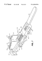
FIG. 7 is a side elevational view of another modified sensor retainer and clasp.
DETAILED DESCRIPTION OF THE PREFERRED EMBODIMENT
Reference will now be made in detail to the preferred embodiments of the invention, examples of which are illustrated in the accompanying drawings. While the invention will be described in conjunction with the preferred embodiments, it will be understood that they are not intended to limit the invention to those embodiments. On the contrary, the invention is intended to cover alternatives, modifications and equivalents, which may be included within the spirit and scope of the invention as defined by the appended claims.
It will be understood that sensors 11 with which the present invention is used are not presently standardized. One commercially available sensor is shown in FIGS. 1 and 2. One of the features of the invention is that the holders are adjustable to accommodate sensors 11 of different dimensions. The particular sensor shown in FIGS. 1 and 2 is manufactured by Schick Technologies, Inc. Model CMOS. Sensor 11 has a front 12, back 13 and side edges 14. At present such sensors 11 are connected to a computer or other electronic recorder by means of wires 16 attached to back 14. It will be understood, of course, that such wires 16 are attached at different positions and the present invention envisions the use of sensors which transmit signals to the computer by means other than wires.
Retaining device 21 shown in FIGS. 3-4 is similar in several respects to that shown in U.S. Pat. 5,256,982. Retainer 21 has a body 22 which is gripped by the teeth of the patient. Body 22 is formed with an irregularly shaped opening 23 defined by a distal end 24 formed with a first rectangular aperture 26, lingual side 27, labial side 28 and proximal end 29 which is formed with second rectangular aperture 31 aligned with aperture 26. Extending out from lingual side 27 are upper and lower projections 32 and 33. Projection 32 is formed with a slanted edge 34 which projects distally outwardly. Projection 33 is formed with a slanted edge 36 parallel to edge 34. Also projecting from the lingual side 27 are wire retaining pins 41 having staggered overhanging heads 42. Thus the wires 16 may be twined around the pins 41 and retained in position by heads 42 so that the wires do not interfere with the x-ray images.
Body 22 has a handle 46 extending proximally out between the teeth of the patient. For adjustment purposes, an arm 47 which also extends out from body 22 at right angles to handle 46 is used to properly adjust the retainer 21 in the jaws of the patient.
Clasp 51 has an elongated shank 52 which fits through the aligned apertures 26 and 27 and is engaged by a detent (not shown) within body 22 which holds the clasp 51 at the desired distance from distal end 24. At outer end 54 of shank 52 is a slanted edge 56, slanting in a direction opposite to edge 34, 36. There is also a grip 57 extending in a direction from end 54 opposite retainer 56 for adjustment of clasp 51 inwardly and outwardly relative to retainer 21.
In use, the sensor is positioned with sensor front 12 engaging shank 52. The slanted surfaces 34, 36 and 56 engage opposite ends 14 of sensor 11 and hold the same in position. Wires 16 are then twined around the pins 41. By manipulation of handle 46 and arm 47 the sensor is positioned within the teeth of the patient in the desired position.
Directing attention now to FIGS. 5-6, a bite block 61 is illustrated which is used to hold the jaws of the patient apart during endodontic surgery. Thus block 61 has a body 62 formed with a downwardly proximally slanted bottom 63. Upstanding sides 64 perpendicular to bottom 63 converge proximally for a purpose which has heretofore been explained. Knobs 66 on the top edges 67 of sides 64 and knobs 68 on the bottom edges thereof are engaged by the teeth of the patient to hold the bite block 61 in position.
Clasp 81 comprises a body 82 which is rectangular in cross-section and has distal parallel extensions 83, the surfaces of which are formed with ratchet teeth 87. At the distal ends of extensions 83 are upstanding ends 84 and at the proximal end of body 82 is an upstanding arm 86.
In use, the clasp body 82 is inserted through the opening 72 and is aligned by fitting under upper guide 73 and over lower guide 74 so that it may move inwardly and outwardly relative to bite block 61 depending on the shape of the sensor 11 used therewith. By means of arm 86 the ends 84 are drawn inwardly so that the sensor 11 is gripped between the distal end of end 71 and the proximal surfaces of ends 84. By means of handle 76 the sensor is then placed in the proper position with regard to the teeth of the patient to be x-rayed. Because the sides 64 converge the shadow cast thereby upon the x-ray sensor is reduced.
The modification shown in FIG. 7 in many respects resembles that shown in FIGS. 3-4 and the same reference numerals followed by subscript are used to designate corresponding parts. As explained in U.S. Pat. 4,945,553, during root canal therapy a bite block, generally wedge-shaped, is incorporated in the holder to hold the patient's jaws apart to provide space for files inserted in teeth during such therapy.
Thus distally downwardly slanted longitudinal member 92 extends upward from shank 32 a. At the proximal end of member 92 is transverse member 93 extending upward from distal end 24 a. A secondary longitudinal member 94 extends proximally from about the midpoint of transverse member. To assist in enabling the teeth to grip body 22 a, protrusions 96 may be formed on the top 97 of member 92 and protrusions 98 on the top 99 of member 93. One respect in which the modification of FIG. 7 differs from FIG. 3—is that there is but a single slanted edge 91 instead of slanted edges 34, 36, of FIGS. 3-4, but either construction may be used.
Preferably there are separate holders for left and right jaws, but the one is a mirror image of the other.
The foregoing descriptions of specific embodiments of the present invention have been presented for purposes of illustration and description. They are not intended to be exhaustive or to limit the invention to the precise forms disclosed, and obviously many modifications and variations are possible in light of the above teaching. The embodiments were chosen and described in order to best explain the principles of the invention and its practical application, to thereby enable others skilled in the art to best utilize the invention and various embodiments with various modifications as are suited to the particular use contemplated. It is intended that the scope of the invention be defined by the Claims appended hereto and their equivalents.