US6212283B1 - Articulation assembly for intracanal hearing devices - Google Patents
Articulation assembly for intracanal hearing devices Download PDFInfo
- Publication number
- US6212283B1 US6212283B1 US08/922,928 US92292897A US6212283B1 US 6212283 B1 US6212283 B1 US 6212283B1 US 92292897 A US92292897 A US 92292897A US 6212283 B1 US6212283 B1 US 6212283B1
- Authority
- US
- United States
- Prior art keywords
- articulation assembly
- modules
- hearing device
- articulation
- ball
- Prior art date
- Legal status (The legal status is an assumption and is not a legal conclusion. Google has not performed a legal analysis and makes no representation as to the accuracy of the status listed.)
- Expired - Fee Related
Links
Images


Classifications
-
- H—ELECTRICITY
- H04—ELECTRIC COMMUNICATION TECHNIQUE
- H04R—LOUDSPEAKERS, MICROPHONES, GRAMOPHONE PICK-UPS OR LIKE ACOUSTIC ELECTROMECHANICAL TRANSDUCERS; DEAF-AID SETS; PUBLIC ADDRESS SYSTEMS
- H04R25/00—Deaf-aid sets, i.e. electro-acoustic or electro-mechanical hearing aids; Electric tinnitus maskers providing an auditory perception
- H04R25/45—Prevention of acoustic reaction, i.e. acoustic oscillatory feedback
- H04R25/456—Prevention of acoustic reaction, i.e. acoustic oscillatory feedback mechanically
-
- H—ELECTRICITY
- H04—ELECTRIC COMMUNICATION TECHNIQUE
- H04R—LOUDSPEAKERS, MICROPHONES, GRAMOPHONE PICK-UPS OR LIKE ACOUSTIC ELECTROMECHANICAL TRANSDUCERS; DEAF-AID SETS; PUBLIC ADDRESS SYSTEMS
- H04R25/00—Deaf-aid sets, i.e. electro-acoustic or electro-mechanical hearing aids; Electric tinnitus maskers providing an auditory perception
- H04R25/65—Housing parts, e.g. shells, tips or moulds, or their manufacture
- H04R25/652—Ear tips; Ear moulds
- H04R25/656—Non-customized, universal ear tips, i.e. ear tips which are not specifically adapted to the size or shape of the ear or ear canal
-
- H—ELECTRICITY
- H04—ELECTRIC COMMUNICATION TECHNIQUE
- H04R—LOUDSPEAKERS, MICROPHONES, GRAMOPHONE PICK-UPS OR LIKE ACOUSTIC ELECTROMECHANICAL TRANSDUCERS; DEAF-AID SETS; PUBLIC ADDRESS SYSTEMS
- H04R25/00—Deaf-aid sets, i.e. electro-acoustic or electro-mechanical hearing aids; Electric tinnitus maskers providing an auditory perception
- H04R25/65—Housing parts, e.g. shells, tips or moulds, or their manufacture
- H04R25/658—Manufacture of housing parts
Definitions
- the invention relates to audio and hearing devices. More particularly, the invention relates to hearing devices that are deeply inserted into the ear canal of an individual.
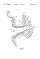
- FIGS. 1 and 2 show a cross-sectional anatomical view of the ear canal in the coronal and transverse planes of the head, respectively.
- the ear canal for the purpose of this invention, can be described as having three segments.
- the first segment represents the medial concha cavity 20 just behind the tragus 21 , which is relatively large and is surrounded by cartilaginous tissue 22 .
- the second cavity 23 medial to the aperture 24 of the external acoustic meatus 11 , is generally smaller and is also surrounded by cartilaginous tissue 22 .
- the third cavity 25 defines the final canal segment near the tympanic membrane 26 and is surrounded by dense bony tissue 27 .
- the tissue 28 lining the cartilaginous region 23 is relatively thick and has a well developed subcutaneous layer thus allowing some expansion to occur.
- the tissue 29 lining the bony region 25 is relatively thin and therefore, little or no tolerance for expansion exists in this region.
- the cartilaginous region 23 is the major area of cerumen (ear-wax) production and accumulation in the ear canal.
- the shape of a typical external ear canal unlike that shown in most artistic renderings is rarely cylindrical or conical with a gradual narrowing towards the tympanic membrane. Instead, most ear canals are non-uniform with various levels of tortuous contours. Some canals have severe restrictions in the cartilaginous area.
- the ear canal is generally “S” shaped with a first bend 30 occurring approximately at the aperture of the ear canal and a second bend 31 at the cartilaginous-bony junction.
- the cross sectional diameter of the ear canal and the orientation of various regions within the canal are known to vary considerably from one individual to another. For example, the length from the aperture 24 to the lateral edge 32 of tympanic membrane 26 ranges from about 20 mm to about 25 mm.
- the cross-sectional shape is generally oval.
- the smallest diameter is generally in the bony region 25 in the transverse plane and ranges from about 4 mm to about 7 mm.
- the largest diameter is in the medial concha region 20 in the coronal plane and ranges from about 10 mm to about 18 mm.
- the morphology of the ear canal reveals substantial deformation within the cartilaginous area 23 of the canal as a result of mandibular motion associated with talking, chewing, yawning, and biting.
- This deformation is generally caused by the asymmetric stresses from the actions of the mandibular condyle 33 on neighboring cartilaginous tissue.
- These deformations have radial components, e.g. constrictions, and axial components, i.e. inward and outward motion. These radial and axial deformations can generally be felt when one inserts a finger in the ear canal and moves the jaw.
- Inserting a receiver (speaker) deeply into the ear canal is desirable for hearing devices such as hearing aids or any earpiece for audio and communication applications. Close proximity of the receiver to the tympanic membrane improves the fidelity and efficiency of sound production. Deeper insertion also improves the external cosmetic appearance of the wearable device as it becomes less conspicuous.
- articulating a receiver module within the ear canal is highly desirable in order to improve wearing comfort as well as maintain an acoustic seal at the receiver area of the hearing device.
- the device In conventional non-articulating hearing aid designs, the device must be “tightly” and precisely fitted in the ear canal in order to prevent sound leakage from the receiver (speaker) outlet of the device into the microphone inlet. These leakages cause acoustic feedback which is manifested by an annoying “whistling” sound. This “air-conducted” feedback is a common problem with many hearing aid users.
- adequate sealing deep within the ear canal is required in order to provide fidelity and efficiency of sound production.
- Another problem with the conventional hearing aid design is the “shell conduction” feedback caused by the common “shell” containing the receiver and the microphone of the device.
- This common housing facilitates the conduction of receiver vibrations to the microphone.
- the above inventions provide a resilient connection in order to provide flexibility in the orientation of the receiver within the ear canal.
- a resilient connection by nature is unduly limited in its range of motion and has a considerable bias for a centering position.
- the electrical wiring contained within the flexible joint is likely to experience damage with use due to the stress of flexing.
- the above inventions do not teach a rigid yet articulated joint for fit and comfort while providing protection to the interconnecting electrical wiring moving within.
- 5,390,254 does not teach means for limiting the range of motion in order to prevent damage to the interconnecting electrical wiring as the ball rotates continuously in a particular direction.
- Another deficiency of U.S. Pat. No. 5,390,254 is that the ball joint assembly substantially intrudes into the hearing device as shown in FIG. 1. This considerable intrusion consumes valuable space within the ear canal, particularly for miniature canal devices that need to be deeply placed within the ear canal.
- Shennib et al. in U.S. patent application Ser. No. 08/365,913 disclose a hearing device with one or more articulated joints as shown in FIGS. 3 and 23. A ball joint articulation is shown in FIGS. 12-14, 20, 24-26.
- the articulated joint of Shennib et al. allows for free movement of the receiver module and also acts as a conduit for electrical conductors to the receiver as shown in the figures.
- the disclosed invention does not teach a space efficient ball joint design, nor does it teach a means to limit rotational movement for protection of electrical wires within.
- a hearing device with a receiver module articulately separate from a main module containing a microphone.
- These modules are articulately separate in order to maximize mechanical and acoustical isolation between the two modules.
- the articulation assembly must be highly compact and durable with rigid structures, yet free to move during insertion and removal or while within the ear canal to accommodate ear canal deformations.
- This invention provides a ball joint assembly for articulated hearing devices that is highly space efficient and reliable.
- the ball joint assembly acoustically and mechanically separates a receiver module, placed deeply within the ear canal near the tympanic membrane, from a main module, placed relatively distal to the tympanic membrane.
- the ball joint assembly allows for independent and free movement of the receiver module with respect to the main module.
- the ball joint assembly has a central axial conduit for conducting electrical wiring from the main module to the receiver module.
- the ball joint assembly has built in rotational stops to limit its rotational movement such that continuous rotation is prevented. These rotational stops prevent damage to the wiring conducted within the ball joint assembly.
- rotational stops are provided by a pair of pins on a spherical ball positioned oppositely along the major axis of an elliptical socket.
- the minor axis of the socket contains a pair of spherical races to accommodate the spherical ball and to provide a smooth and nearly friction-free movement.
- the ball and the socket are made of relatively rigid material such as metal or hard plastic, thus providing an extremely durable articulation assembly.
- the ball joint assembly of the preferred embodiment is relatively fully-contained within the wall of the main housing, thus minimizing the size of the hearing device. This also allows for deep and comfortable placement within the ear canal. Size reduction and deep insertion allow for a more inconspicuous placement of the hearing device, a major advantage in any hearing device design.
- a flexible boot covering the articulated ball joint assembly protects the ball joint from cerumen and other debris and provides a bias force for orienting the receiver module and facilitating the insertion of the device into the ear canal.
- this bias force is minimal thus allowing the articulated modules to move relatively freely with respect to each other within the ear canal.
- FIG. 1 is an anatomical view of an ear canal in the coronal plane
- FIG. 2 is an anatomical view of an ear in the transverse plane
- FIG. 3 shows a side view of an articulated hearing device in the transverse plane
- FIG. 4 shows a detailed side view of the articulation assembly in the preferred embodiment
- FIG. 5 shows the receiver module of an articulation assembly and the degrees of freedom it has to move relative to the main module.
- FIG. 6 is cross section of the articulation assembly showing stop pins for limiting the range of rotational movement
- FIG. 7 shows a cross section of an articulation assembly with integrated ball, shaft and receiver housing
- FIG. 8 shows another embodiment of the articulation joint with ball socket integrated within main housing of hearing device
- FIG. 9 shows a ball joint assembly coupled to main housing via a vibration damper ring
- FIG. 10 shows another embodiment of the articulation joint with an interiorly extended shaft and stop pin
- FIG. 11 shows an orthogonal view of the interiorly extended shaft and stop pin
- FIG. 12 shows an embodiment of articulation assembly with a receiver partially inserted in ball head
- FIG. 13 shows a tool for placing a boot on the articulation assembly
- FIG. 14 shows an intracanal hearing device with two articulation joints and a connecting shaft
- FIG. 15 shows an articulation assembly connected to an extended main housing shaft
- FIG. 16 shows an articulated intracanal earpiece
- FIG. 17 shows an intracanal transducer for hearing evaluation and hearing aid simulation.
- the invention described herein is used for coupling acoustic signals in the ear canal of an individual.
- the articulated assembly of the present invention is adapted for use with any hearing device or any audio system for the coupling of sound deeply and comfortably into the ear canal.
- the invention is particularly applicable for use in conjunction with the Articulated Hearing Device described by Shennib, et al. in U.S. patent application Ser. No. 08/365,913 filed on Dec. 29, 1994, and with the Acoustic Coupler described by Shennib, et al in U.S. patent application Ser. No. 08/902,401 filed on Jul. 29, 1997.
- the separation and articulation of hearing aid modules is desirable for many reasons including acoustic feedback control, greater ease of insertion deep into the ear canal, comfort while within the ear canal, and reduction of device size. Articulation is also desirable in order to allow parts of the hearing device to move independently in situ (within the ear canal) in response to canal deformation during various jaw movements.
- the present invention provides a highly compact and durable articulation for use with any intracanal hearing device or earpiece.
- FIG. 3 An example of an articulated hearing device with articulation assembly of the present invention is shown in FIG. 3 .
- Main module 40 articulates with receiver module 50 via articulation assembly 60 which is shown in more details in the following figures.
- Main module 40 consists of main housing 41 which contains typical hearing aid components such as a battery 42 , microphone 43 , signal processing circuit 44 , and other components such as adjustment controls or programming ports, not shown in the figure but well known in the field of hearing aid design.
- Electrical wires 52 (FIG. 4) from the main module 40 are routed through the center of articulation assembly 60 for connection to receiver terminals 77 of a receiver (speaker) 54 contained within receiver housing 51 .
- An acoustic coupler 53 (FIG. 3) provides a conforming acoustic seal for improved comfort and feedback control as disclosed in U.S. patent application Ser. No. 08/902,401 filed on Jul. 29, 1997.
- the articulation assembly 60 is covered by a flexible boot 48 which protects the articulation assembly from environmental and physiologic residue, including cerumen (earwax).
- the boot 48 is fitted to the receiver housing via a boot groove 56 formed by a lateral ring 57 and a medial ring 58 (medial and lateral with respect to the tympanic membrane 26 ).
- the boot 48 is also fitted to the main module 40 via a second boot groove 67 formed by a medial ring 68 on the ball socket and the wall of the main housing 41 .
- Articulation assembly 60 contains a ball head 61 , ball socket 62 and a connecting shaft 55 for connecting the ball head to the receiver housing 51 .
- Ball head 61 and connecting shaft 55 contain conduit 66 for routing electrical wires 52 which electrically connect signal and power to the receiver module 50 .
- the articulation assembly 60 of the present invention allows the receiver module 50 to move with respect to the main module 40 in a conic section with at least two degrees of freedom as shown in FIG. 5 .
- This articulation allows the modules of the hearing device to adapt to the unique bends of an individual's ear canal. Movements in an XYZ sphere of radius R, bounded by a conic section as shown, are referred to here collectively as “axial” movements since they affect the axial orientation of the receiver module 50 with respect to the main module 40 .
- Rotational movements represent the rotational movement of the receiver module 50 around its own axis as shown by arrow M R in FIG. 5 .
- Articulation assembly 60 of the preferred embodiment is shown in greater detail in FIGS. 6, and 7 .
- Ball head 61 is partially contained in an elliptical ball socket 62 (FIG. 6) with two spherical races 63 , one on each side of the minor axis of the elliptical ball socket 62 .
- Ball head 61 has two stop pins 65 , oppositely positioned in the relieved areas 64 of the ball socket 62 .
- Relieved areas 64 allow the stop pins 65 to rotate as far as the edges of the relieved area.
- the shape and extent of the relieved area 64 define the range of rotational movement as shown by arrow 70 in FIG. 6 .
- Axial movement is also limited by features within the articulation assembly.
- the relationship between an interiorly extended flange 74 on the ball head and the medial edge 76 of the socket 62 defines the range of axial movement as shown by arrow 75 in FIG. 7 .
- Axial movement may also be limited by features partially external to the articulation assembly such as the shaft 55 or boot rings 57 and 68 as shown in FIG. 6 .
- a short shaft 55 produces a range of axial movement limited by boot rings 57 and 68 as shown by arrow 71 in FIG. 7.
- a relatively wider range of axial movement can be achieved by a longer shaft 55 (not shown) where the range becomes limited by the shaft 55 itself and the side of the ring 68 .
- Other features for limiting range of motion are possible once the principles disclosed above are understood by persons skilled in the art.
- the articulation assembly and the associated range limiting features as shown in the figures are highly compact and can be placed essentially flush with wall 41 of main housing 40 instead of protruding within.
- a wire strain relief means 45 encapsulating the electrical wires 52 can be placed on the interior of the main module 40 , near or at the ball socket 62 as shown in FIG. 4 .
- the strain relief means 45 can also be inserted within the conduit 66 as shown in FIG. 6 .
- Wire strain relief can be achieved by soft tubing, as shown in the figures, or by injecting a non-hardening gel or gel-like material (not shown) within the conduit 66 or outside the conduit around the moving portion of electrical wiring 52 .
- the ball head 61 may be a separate part but attached to the shaft 55 as shown in FIG. 4 .
- the ball head 61 may be an integral part of the shaft 55 and the receiver housing 51 as shown in FIG. 7.
- a singular molded design is generally preferred because it leads to a more durable design and allows a more cost-effective manufacturing process.
- the ball socket 62 may be integrated within main housing 41 as shown in FIG. 8 .
- Boot grooves 67 and 56 are also molded in the main housing 41 and receiver housing 51 as shown in FIG. 8 .
- the boot 48 is preferably made of a flexible viscoelastic material in order to isolate the vibrations of the receiver module 50 from the main module 40 , thus minimizing occurrence of feedback.
- a bellows-like boot design 48 is shown in FIG. 8 to further facilitate axial movement of the receiver module.
- the flexible boot is preferably elastomeric to provide a minimal bias force to orient the receiver module 50 with respect to the main module 40 prior to device insertion into the ear canal.
- This bias force provides a proper and consistent orientation of the receiver module to facilitate insertion, particularly for persons of limited manual dexterity.
- the boot's elastomeric force is relatively weak thus allowing the articulated modules to freely assume any position according to the shape and contours within an individual's ear canal.
- the flexible boot can be color coded to differentiate right and left devices for the user. This is desirable since miniature devices often look similar leading the user to incorrectly insert a right device in left ear for example.
- the hearing aid industry had long adapted Red for Right and Blue for Left. It is therefore desirable to provide Red/Blue colored boot for Right/Left ears, respectively.
- FIG. 9 shows a placement forceps 90 with grooves 91 for holding and expanding the boot 48 prior to releasing it for placement within receiver boot groove 56 and main module boot groove 67 .
- a vibration damper ring 46 is provided between the ball socket 62 and the main housing wall 41 as shown in FIG. 10 .
- the vibration damper ring 46 is preferably made of a durable viscoelastic material such as certain types of rubber.
- a lubricant 49 coating the ball head 61 further provides mechano-acoustic isolation as well as minimizing friction between the ball head 61 and ball socket 62 .
- the lubricant material may be petroleum-based such as Chevron SRI-2 or a fluorinated grease such as Krytox 240-AC.
- FIGS. 11 and 12 Another embodiment of the articulation assembly of the present invention with range of motion limiting features partially contained within articulation assembly is shown in FIGS. 11 and 12.
- a stop pin column 65 is inserted in shaft protrusion 59 extending inwardly toward the center of the main module 40 .
- the ball socket has inwardly extended edge 76 to limit the motion of stop pin column 65 .
- the rotational articulation range is limited by the relationship of the stop pin 65 and extended edge 76 as shown in FIGS. 11 and 12.
- the ball head 61 is continuous with the receiver housing 51 , and the receiver 54 is partially housed within the ball head 61 .
- Medial and lateral receiver dampers, 84 and 85 respectively, mechano-acoustically isolate the receiver 54 from the receiver housing 51 and the ball head 61 .
- a debris guard 87 near the receiver sound port 86 , protects the receiver 54 from environmental and physiologic residue, including cerumen (earwax).
- a miniature elongated receiver such as model SD series manufactured by Knowles Electronics, Inc. of Itasca, Ill. is particularly suited for insertion into a miniature ball head of the articulation assembly of the present invention.
- Receiver housing threads 78 secure the attachment of acoustic coupler 53 .
- FIG. 14 Another embodiment of the present invention provides two articulation joints as shown in FIG. 14 .
- the first articulation assembly is embedded within the wall of the main housing 41 as discussed above.
- a second articulation assembly is at the lateral end of the receiver module 50 with a second ball head 78 and a second ball socket 79 .
- a shaft 55 connects ball heads 61 and 78 .
- the advantages of this dual articulation system include increased depth of receiver insertion into the ear canal and increased flexibility within.
- Each articulation includes stops (not shown) as discussed above for limiting the range of articulation and preserving the electromechanical integrity of the joints and wiring within.
- strain relief means 45 for protecting the electrical wiring 52 at the second articulation assembly is required, particularly near the receiver terminals 77 as shown in FIG. 14 .
- FIG. 15 Another embodiment of the present invention is a hearing device with a medially extended main housing shaft 47 as shown in FIG. 15 .
- the main housing shaft 47 comprises a ball socket 62 at its medial end which encapsulates the ball head 61 connected to a receiver housing 51 via a shaft 55 .
- range of motion stops (not shown) are contained within the ball joint assembly as disclosed above for limiting one or more degrees of motion.
- This invention is mainly concerned with providing an articulation assembly for use with any modular intracanal hearing device.
- the modules of a hearing device may be configured entirely differently from the examples described above.
- a receiver module may contain a battery in addition to a receiver.
- the main module may include or exclude other components as necessary for the operation of the hearing device.
- the configuration of the components within the articulated modules is not particularly relevant to the present invention which primarily deals with providing a highly efficient articulation assembly for use within the ear canal.
- FIG. 16 shows an articulated earpiece 80 as a part of an audio system external to the ear canal but coupled, either electrically via signal cable 82 or by other means (not shown).
- a handle 81 facilitates insertion and removal as well as providing strain relief for the cable wires 83 within the signal cable 82 .
- Other means to couple audio signals into the earpiece include a wireless link such as radio frequency (RF) or infrared (IR).
- RF radio frequency
- IR infrared
- Another application of the invented articulation assembly is for use with intracanal transducers during hearing evaluation or hearing aid simulation as shown in FIG. 17 .
- intracanal transducers during hearing evaluation or hearing aid simulation as shown in FIG. 17 .
- pure tones or any other audiologically significant signals such as speech, music or noise, are produced to assess the hearing ability or profile of an individual.
- acoustic signals representative of those produced by a hearing aid can be produced by an intracanal transducer to simulate the performance of a prescribed hearing aid.
- an intracanal transducer 90 is connected via a signal cable 82 to an audiometric module or an appropriate signal generating device external to the ear canal (not shown).
- These externally produced electrical signals are conducted via electrical wiring 52 within the intracanal transducer 90 and are then delivered via articulation assembly 60 to a receiver 54 within a receiver module 50 .
- the receiver 54 produces acoustic signals 87 (near the tympanic membrane 26 ) that are representative of audiometric signals for hearing evaluation, or representative of a simulated hearing aid.
- the acoustic signals 87 are then measured simultaneously by an intracanal probe tube 94 with its tip 98 positioned within close proximity to the tympanic membrane.
- the intracanal probe tube 94 is connected to a microphone amplifier assembly 95 which converts the measured acoustic signals 87 to electrical signals via a measuring signal cable 96 .
- the measured electrical signal is then connected to an audiometric module or to the appropriate measuring device (not shown).
- articulation assembly of the present invention is not limited to hearing aids, audio and communication earpieces, hearing evaluation or hearing aid simulation applications as mentioned in the above examples.
- Other applications for delivering acoustic signals deeply and comfortably within the ear canal should become obvious once the principles of, the present invention are disclosed and understood.
Abstract
Description
Claims (66)
Priority Applications (1)
| Application Number | Priority Date | Filing Date | Title |
|---|---|---|---|
| US08/922,928 US6212283B1 (en) | 1997-09-03 | 1997-09-03 | Articulation assembly for intracanal hearing devices |
Applications Claiming Priority (1)
| Application Number | Priority Date | Filing Date | Title |
|---|---|---|---|
| US08/922,928 US6212283B1 (en) | 1997-09-03 | 1997-09-03 | Articulation assembly for intracanal hearing devices |
Publications (1)
| Publication Number | Publication Date |
|---|---|
| US6212283B1 true US6212283B1 (en) | 2001-04-03 |
Family
ID=25447811
Family Applications (1)
| Application Number | Title | Priority Date | Filing Date |
|---|---|---|---|
| US08/922,928 Expired - Fee Related US6212283B1 (en) | 1997-09-03 | 1997-09-03 | Articulation assembly for intracanal hearing devices |
Country Status (1)
| Country | Link |
|---|---|
| US (1) | US6212283B1 (en) |
Cited By (59)
| Publication number | Priority date | Publication date | Assignee | Title |
|---|---|---|---|---|
| US6585075B1 (en) * | 2000-10-23 | 2003-07-01 | Edouard A. Gauthier | Hearing aid having hard mounted speaker and energy absorbing tip |
| US20040081328A1 (en) * | 1996-03-14 | 2004-04-29 | Sarnoff Corporation | Hearing aid |
| US20040165742A1 (en) * | 1999-04-29 | 2004-08-26 | Insound Medical, Inc. | Canal hearing device with tubular insert |
| US20050190938A1 (en) * | 2004-02-05 | 2005-09-01 | Insound Medical, Inc. | Extended wear canal device with common microphone-battery air cavity |
| US6940988B1 (en) * | 1998-11-25 | 2005-09-06 | Insound Medical, Inc. | Semi-permanent canal hearing device |
| US20050259840A1 (en) * | 1999-06-08 | 2005-11-24 | Insound Medical, Inc. | Precision micro-hole for extended life batteries |
| US20060050914A1 (en) * | 1998-11-25 | 2006-03-09 | Insound Medical, Inc. | Sealing retainer for extended wear hearing devices |
| US20070003087A1 (en) * | 2005-06-30 | 2007-01-04 | Insound Medical, Inc. | Hearing aid microphone protective barrier |
| DE102006035066A1 (en) * | 2006-07-28 | 2008-01-31 | Siemens Audiologische Technik Gmbh | Ear insertion arrangement for hearing aid system, has external region accessible in assigned condition of arrangement from outside, where flexibly ductile area i.e. joint, is provided between regions |
| US20080137891A1 (en) * | 2005-05-13 | 2008-06-12 | Cesar Guilherme Vohringer | Cic Hearing Aid |
| US20080247581A1 (en) * | 2007-04-04 | 2008-10-09 | Siemens Hearing Instruments Inc. | Construction of A Completely-In-Canal Hearing Instrument With Receiver Compartment |
| US20090034770A1 (en) * | 2007-08-03 | 2009-02-05 | Siemens Medical Intruments Pte:- Ltd. | Receiver device with manipulable sound outlet direction |
| US20090074220A1 (en) * | 2007-08-14 | 2009-03-19 | Insound Medical, Inc. | Combined microphone and receiver assembly for extended wear canal hearing devices |
| WO2009120149A1 (en) * | 2008-03-27 | 2009-10-01 | Siemens Medical Instruments Pte. Ltd. | Hearing aid |
| WO2010014136A1 (en) * | 2008-07-31 | 2010-02-04 | Medical Research Products-B, Inc. | Hearing aid system including implantable housing having ear canal mounted transducer speaker and microphone |
| EP2180723A1 (en) | 2008-10-22 | 2010-04-28 | Siemens Medical Instruments Pte. Ltd. | Hearing aid with mobile earpiece |
| US20100322452A1 (en) * | 2004-02-05 | 2010-12-23 | Insound Medical, Inc. | Contamination resistant ports for hearing devices |
| US20110058697A1 (en) * | 2009-09-10 | 2011-03-10 | iHear Medical, Inc. | Canal Hearing Device with Disposable Battery Module |
| DE102010022324A1 (en) * | 2010-06-01 | 2011-12-01 | Siemens Medical Instruments Pte. Ltd. | Hearing instrument i.e. deep-ear-canal hearing aid, for use by hearing-impaired person, has input transducer, signal processing device and generator that are arranged in housing, where housing and earpiece are connected to each other |
| US20120237065A1 (en) * | 2011-03-18 | 2012-09-20 | Starkey Laboratories, Inc. | Ball and socket connection with an acoustic seal and mounting interface for a hearing assistance device |
| WO2012130294A1 (en) | 2011-03-29 | 2012-10-04 | Phonak Ag | Cic hearing aid |
| CN103069841A (en) * | 2010-08-03 | 2013-04-24 | 峰力公司 | Receiver system for a hearing instrument |
| EP2180725A3 (en) * | 2008-10-22 | 2013-10-30 | Siemens Medical Instruments Pte. Ltd. | Hearing aid with oscillation decoupled earpiece |
| US8682016B2 (en) | 2011-11-23 | 2014-03-25 | Insound Medical, Inc. | Canal hearing devices and batteries for use with same |
| US8693719B2 (en) | 2010-10-08 | 2014-04-08 | Starkey Laboratories, Inc. | Adjustment and cleaning tool for a hearing assistance device |
| US8761423B2 (en) | 2011-11-23 | 2014-06-24 | Insound Medical, Inc. | Canal hearing devices and batteries for use with same |
| US8798301B2 (en) | 2012-05-01 | 2014-08-05 | iHear Medical, Inc. | Tool for removal of canal hearing device from ear canal |
| US8808906B2 (en) | 2011-11-23 | 2014-08-19 | Insound Medical, Inc. | Canal hearing devices and batteries for use with same |
| US8855345B2 (en) | 2012-03-19 | 2014-10-07 | iHear Medical, Inc. | Battery module for perpendicular docking into a canal hearing device |
| US8867768B2 (en) | 2012-11-30 | 2014-10-21 | iHear Medical, Inc. | Earpiece assembly with foil clip |
| US9031247B2 (en) | 2013-07-16 | 2015-05-12 | iHear Medical, Inc. | Hearing aid fitting systems and methods using sound segments representing relevant soundscape |
| US9060233B2 (en) | 2013-03-06 | 2015-06-16 | iHear Medical, Inc. | Rechargeable canal hearing device and systems |
| US9078075B2 (en) | 2012-11-30 | 2015-07-07 | iHear Medical, Inc. | Tool for insertion of canal hearing device into the ear canal |
| US9088852B2 (en) | 2013-03-06 | 2015-07-21 | iHear Medical, Inc. | Disengagement tool for a modular canal hearing device and systems including same |
| US9107016B2 (en) | 2013-07-16 | 2015-08-11 | iHear Medical, Inc. | Interactive hearing aid fitting system and methods |
| EP2930944A1 (en) * | 2014-04-07 | 2015-10-14 | Oticon A/s | Hearing aid comprising a flexible connection member |
| US9185504B2 (en) | 2012-11-30 | 2015-11-10 | iHear Medical, Inc. | Dynamic pressure vent for canal hearing devices |
| US9326706B2 (en) | 2013-07-16 | 2016-05-03 | iHear Medical, Inc. | Hearing profile test system and method |
| US9369816B2 (en) | 2009-12-31 | 2016-06-14 | Starkey Laboratories, Inc. | Omniphobic perforated barrier for hearing aid transducers |
| US9439008B2 (en) | 2013-07-16 | 2016-09-06 | iHear Medical, Inc. | Online hearing aid fitting system and methods for non-expert user |
| EP3086573A1 (en) * | 2015-04-20 | 2016-10-26 | Oticon A/s | A hearing device configured to be placed in the ear canal of a user |
| EP3099082A1 (en) * | 2015-05-27 | 2016-11-30 | Jerome C Ruzicka | Self-aligning comfort fit retention arm for a hearing assistance device |
| US9604325B2 (en) | 2011-11-23 | 2017-03-28 | Phonak, LLC | Canal hearing devices and batteries for use with same |
| US9769577B2 (en) | 2014-08-22 | 2017-09-19 | iHear Medical, Inc. | Hearing device and methods for wireless remote control of an appliance |
| US9788126B2 (en) | 2014-09-15 | 2017-10-10 | iHear Medical, Inc. | Canal hearing device with elongate frequency shaping sound channel |
| US9805590B2 (en) | 2014-08-15 | 2017-10-31 | iHear Medical, Inc. | Hearing device and methods for wireless remote control of an appliance |
| US9807524B2 (en) | 2014-08-30 | 2017-10-31 | iHear Medical, Inc. | Trenched sealing retainer for canal hearing device |
| US10045128B2 (en) | 2015-01-07 | 2018-08-07 | iHear Medical, Inc. | Hearing device test system for non-expert user at home and non-clinical settings |
| US10085678B2 (en) | 2014-12-16 | 2018-10-02 | iHear Medical, Inc. | System and method for determining WHO grading of hearing impairment |
| US10097933B2 (en) | 2014-10-06 | 2018-10-09 | iHear Medical, Inc. | Subscription-controlled charging of a hearing device |
| US10284974B2 (en) | 2013-07-10 | 2019-05-07 | Starkey Laboratories, Inc. | Acoustically transparent barrier layer to seal audio transducers |
| US10341790B2 (en) | 2015-12-04 | 2019-07-02 | iHear Medical, Inc. | Self-fitting of a hearing device |
| US10489833B2 (en) | 2015-05-29 | 2019-11-26 | iHear Medical, Inc. | Remote verification of hearing device for e-commerce transaction |
| US10629969B2 (en) | 2014-07-27 | 2020-04-21 | Sonova Ag | Batteries and battery manufacturing methods |
| EP3739905A1 (en) * | 2019-05-13 | 2020-11-18 | Sonova AG | Earpiece for the ear canal with off-axis electronic package and receiver |
| US11115519B2 (en) | 2014-11-11 | 2021-09-07 | K/S Himpp | Subscription-based wireless service for a hearing device |
| US11134352B2 (en) | 2020-01-29 | 2021-09-28 | Sonova Ag | Hearing device with wax guard interface |
| US11331008B2 (en) | 2014-09-08 | 2022-05-17 | K/S Himpp | Hearing test system for non-expert user with built-in calibration and method |
| US11638108B2 (en) | 2020-11-27 | 2023-04-25 | Sonova Ag | Canal hearing devices with sound port contaminant guards |
Citations (7)
| Publication number | Priority date | Publication date | Assignee | Title |
|---|---|---|---|---|
| US3061689A (en) | 1957-05-27 | 1962-10-30 | Beltone Hearing Aid Company | Hearing aid |
| USRE26258E (en) | 1964-04-02 | 1967-08-29 | In-the-ear hearing aid | |
| US3404685A (en) | 1967-01-30 | 1968-10-08 | S E & M Vernon Inc | Ring binder |
| US3527901A (en) | 1967-03-28 | 1970-09-08 | Dahlberg Electronics | Hearing aid having resilient housing |
| US5390254A (en) | 1991-01-17 | 1995-02-14 | Adelman; Roger A. | Hearing apparatus |
| US5701348A (en) * | 1994-12-29 | 1997-12-23 | Decibel Instruments, Inc. | Articulated hearing device |
| US5784471A (en) * | 1995-07-15 | 1998-07-21 | Sennheiser Electronic Gmbh & Co. Kg | Hearing aid with an electrodynamic acoustic transducer |
-
1997
- 1997-09-03 US US08/922,928 patent/US6212283B1/en not_active Expired - Fee Related
Patent Citations (7)
| Publication number | Priority date | Publication date | Assignee | Title |
|---|---|---|---|---|
| US3061689A (en) | 1957-05-27 | 1962-10-30 | Beltone Hearing Aid Company | Hearing aid |
| USRE26258E (en) | 1964-04-02 | 1967-08-29 | In-the-ear hearing aid | |
| US3404685A (en) | 1967-01-30 | 1968-10-08 | S E & M Vernon Inc | Ring binder |
| US3527901A (en) | 1967-03-28 | 1970-09-08 | Dahlberg Electronics | Hearing aid having resilient housing |
| US5390254A (en) | 1991-01-17 | 1995-02-14 | Adelman; Roger A. | Hearing apparatus |
| US5701348A (en) * | 1994-12-29 | 1997-12-23 | Decibel Instruments, Inc. | Articulated hearing device |
| US5784471A (en) * | 1995-07-15 | 1998-07-21 | Sennheiser Electronic Gmbh & Co. Kg | Hearing aid with an electrodynamic acoustic transducer |
Non-Patent Citations (5)
| Title |
|---|
| Gudmundsen, "Fitting CIC Hearing Aids-Some Practical Pointers," The Hearing Journal, vol. 47, No. 7, Jul. 1994. |
| Gudmundsen, "Fitting CIC Hearing Aids—Some Practical Pointers," The Hearing Journal, vol. 47, No. 7, Jul. 1994. |
| Oliveira, et al., "A Look at Ear Canal Changes with Jaw Motion," Ear and Hearing, vol. 13, No. 6, 1992. |
| Shennib et al., Patent Application Entitled "Acoustic Coupler" U.S. Serial No. 08/902,401, filed Jul. 29, 1997. |
| Shennib et al., Patent Application Entitled "Articulated Hearing Device", U.S. Serial No. 08/365,913, filed Dec. 29, 1994. |
Cited By (115)
| Publication number | Priority date | Publication date | Assignee | Title |
|---|---|---|---|---|
| US20040081328A1 (en) * | 1996-03-14 | 2004-04-29 | Sarnoff Corporation | Hearing aid |
| US7987977B2 (en) | 1996-03-14 | 2011-08-02 | Sarnoff Corporation | Hearing aid package |
| US20040240695A1 (en) * | 1996-03-14 | 2004-12-02 | Sarnoff Corporation | Hearing aid |
| US7536023B2 (en) | 1996-03-14 | 2009-05-19 | Sarnoff Corporation | Hearing aid |
| US7010137B1 (en) | 1997-03-12 | 2006-03-07 | Sarnoff Corporation | Hearing aid |
| US8538055B2 (en) | 1998-11-25 | 2013-09-17 | Insound Medical, Inc. | Semi-permanent canal hearing device and insertion method |
| US20080137892A1 (en) * | 1998-11-25 | 2008-06-12 | Insound Medical, Inc. | Semi-permanent canal hearing device and insertion method |
| US6940988B1 (en) * | 1998-11-25 | 2005-09-06 | Insound Medical, Inc. | Semi-permanent canal hearing device |
| US20060050914A1 (en) * | 1998-11-25 | 2006-03-09 | Insound Medical, Inc. | Sealing retainer for extended wear hearing devices |
| US20100098281A1 (en) * | 1998-11-25 | 2010-04-22 | Insound Medical, Inc. | Sealing retainer for extended wear hearing devices |
| US7664282B2 (en) | 1998-11-25 | 2010-02-16 | Insound Medical, Inc. | Sealing retainer for extended wear hearing devices |
| US8503707B2 (en) | 1998-11-25 | 2013-08-06 | Insound Medical, Inc. | Sealing retainer for extended wear hearing devices |
| US7424124B2 (en) | 1998-11-25 | 2008-09-09 | Insound Medical, Inc. | Semi-permanent canal hearing device |
| US20040165742A1 (en) * | 1999-04-29 | 2004-08-26 | Insound Medical, Inc. | Canal hearing device with tubular insert |
| US7424123B2 (en) * | 1999-04-29 | 2008-09-09 | Insound Medical, Inc. | Canal hearing device with tubular insert |
| US8068630B2 (en) | 1999-06-08 | 2011-11-29 | Insound Medical, Inc. | Precision micro-hole for extended life batteries |
| US8666101B2 (en) | 1999-06-08 | 2014-03-04 | Insound Medical, Inc. | Precision micro-hole for extended life batteries |
| US7379555B2 (en) | 1999-06-08 | 2008-05-27 | Insound Medical, Inc. | Precision micro-hole for extended life batteries |
| US20080069386A1 (en) * | 1999-06-08 | 2008-03-20 | Insound Medical, Inc. | Precision micro-hole for extended life batteries |
| US20050259840A1 (en) * | 1999-06-08 | 2005-11-24 | Insound Medical, Inc. | Precision micro-hole for extended life batteries |
| US6585075B1 (en) * | 2000-10-23 | 2003-07-01 | Edouard A. Gauthier | Hearing aid having hard mounted speaker and energy absorbing tip |
| US20080031482A1 (en) * | 2004-02-05 | 2008-02-07 | Insound Medical, Inc. | Extended wear canal device with common microphone-battery air cavity |
| WO2005076991A3 (en) * | 2004-02-05 | 2007-01-25 | Insound Medical Inc | Extended wear canal device with common microphone-battery air cavity |
| US20050190938A1 (en) * | 2004-02-05 | 2005-09-01 | Insound Medical, Inc. | Extended wear canal device with common microphone-battery air cavity |
| US8036407B2 (en) | 2004-02-05 | 2011-10-11 | Insound Medical, Inc. | Extended wear canal device with common microphone-battery air cavity |
| US20100322452A1 (en) * | 2004-02-05 | 2010-12-23 | Insound Medical, Inc. | Contamination resistant ports for hearing devices |
| US8457336B2 (en) | 2004-02-05 | 2013-06-04 | Insound Medical, Inc. | Contamination resistant ports for hearing devices |
| US7298857B2 (en) | 2004-02-05 | 2007-11-20 | Insound Medical, Inc. | Extended wear canal device with common microphone-battery air cavity |
| US20080137891A1 (en) * | 2005-05-13 | 2008-06-12 | Cesar Guilherme Vohringer | Cic Hearing Aid |
| US8494200B2 (en) | 2005-06-30 | 2013-07-23 | Insound Medical, Inc. | Hearing aid microphone protective barrier |
| US7876919B2 (en) | 2005-06-30 | 2011-01-25 | Insound Medical, Inc. | Hearing aid microphone protective barrier |
| US20070003087A1 (en) * | 2005-06-30 | 2007-01-04 | Insound Medical, Inc. | Hearing aid microphone protective barrier |
| US20110085688A1 (en) * | 2005-06-30 | 2011-04-14 | Insound Medical, Inc. | Hearing aid microphone protective barrier |
| DE102006035066A1 (en) * | 2006-07-28 | 2008-01-31 | Siemens Audiologische Technik Gmbh | Ear insertion arrangement for hearing aid system, has external region accessible in assigned condition of arrangement from outside, where flexibly ductile area i.e. joint, is provided between regions |
| US20080247581A1 (en) * | 2007-04-04 | 2008-10-09 | Siemens Hearing Instruments Inc. | Construction of A Completely-In-Canal Hearing Instrument With Receiver Compartment |
| US8068631B2 (en) * | 2007-04-04 | 2011-11-29 | Siemens Hearing Instruments Inc. | Construction of a completely-in-canal hearing instrument with receiver compartment |
| US20090034770A1 (en) * | 2007-08-03 | 2009-02-05 | Siemens Medical Intruments Pte:- Ltd. | Receiver device with manipulable sound outlet direction |
| US8098866B2 (en) * | 2007-08-03 | 2012-01-17 | Siemens Medical Instruments Pte. Ltd. | Receiver device with manipulable sound outlet direction |
| EP2177046A2 (en) * | 2007-08-14 | 2010-04-21 | Insound Medical, Inc | Combined microphone and receiver assembly for extended wear canal hearing devices |
| US9071914B2 (en) | 2007-08-14 | 2015-06-30 | Insound Medical, Inc. | Combined microphone and receiver assembly for extended wear canal hearing devices |
| US20090074220A1 (en) * | 2007-08-14 | 2009-03-19 | Insound Medical, Inc. | Combined microphone and receiver assembly for extended wear canal hearing devices |
| EP2177046B1 (en) | 2007-08-14 | 2017-03-15 | Insound Medical, Inc | Combined microphone and receiver assembly for extended wear canal hearing devices |
| EP2177046B2 (en) † | 2007-08-14 | 2020-05-27 | Insound Medical, Inc | Combined microphone and receiver assembly for extended wear canal hearing devices |
| WO2009023738A3 (en) * | 2007-08-14 | 2010-01-14 | Insound Medical, Inc. | Combined microphone and receiver assembly for extended wear canal hearing devices |
| EP2177046A4 (en) * | 2007-08-14 | 2014-01-08 | Insound Medical Inc | Combined microphone and receiver assembly for extended wear canal hearing devices |
| US8411890B2 (en) | 2008-03-27 | 2013-04-02 | Siemens Medical Instruments Pte. Ltd. | Hearing aid |
| US20110019850A1 (en) * | 2008-03-27 | 2011-01-27 | Siemens Medical Instruments Pte. Ltd. | Hearing aid |
| WO2009120149A1 (en) * | 2008-03-27 | 2009-10-01 | Siemens Medical Instruments Pte. Ltd. | Hearing aid |
| WO2010014136A1 (en) * | 2008-07-31 | 2010-02-04 | Medical Research Products-B, Inc. | Hearing aid system including implantable housing having ear canal mounted transducer speaker and microphone |
| EP2180725A3 (en) * | 2008-10-22 | 2013-10-30 | Siemens Medical Instruments Pte. Ltd. | Hearing aid with oscillation decoupled earpiece |
| EP2180723A1 (en) | 2008-10-22 | 2010-04-28 | Siemens Medical Instruments Pte. Ltd. | Hearing aid with mobile earpiece |
| US20110058697A1 (en) * | 2009-09-10 | 2011-03-10 | iHear Medical, Inc. | Canal Hearing Device with Disposable Battery Module |
| US8467556B2 (en) | 2009-09-10 | 2013-06-18 | iHear Medical, Inc. | Canal hearing device with disposable battery module |
| US9369816B2 (en) | 2009-12-31 | 2016-06-14 | Starkey Laboratories, Inc. | Omniphobic perforated barrier for hearing aid transducers |
| DE102010022324A1 (en) * | 2010-06-01 | 2011-12-01 | Siemens Medical Instruments Pte. Ltd. | Hearing instrument i.e. deep-ear-canal hearing aid, for use by hearing-impaired person, has input transducer, signal processing device and generator that are arranged in housing, where housing and earpiece are connected to each other |
| CN103069841A (en) * | 2010-08-03 | 2013-04-24 | 峰力公司 | Receiver system for a hearing instrument |
| US9088853B2 (en) * | 2010-08-03 | 2015-07-21 | Phonak Ag | Receiver system for a hearing instrument |
| US20130182877A1 (en) * | 2010-08-03 | 2013-07-18 | Phonak Ag | Receiver system for a hearing instrument |
| US8693719B2 (en) | 2010-10-08 | 2014-04-08 | Starkey Laboratories, Inc. | Adjustment and cleaning tool for a hearing assistance device |
| US9002049B2 (en) | 2010-10-08 | 2015-04-07 | Starkey Laboratories, Inc. | Housing for a standard fit hearing assistance device |
| US8848956B2 (en) | 2010-10-08 | 2014-09-30 | Starkey Laboratories, Inc. | Standard fit hearing assistance device with removable sleeve |
| US9071918B2 (en) * | 2011-03-18 | 2015-06-30 | Starkey Laboratories, Inc. | Ball and socket connection with an acoustic seal and mounting interface for a hearing assistance device |
| US9980065B2 (en) * | 2011-03-18 | 2018-05-22 | Starkey Laboratories, Inc. | Ball and socket connection with an acoustic seal and mounting interface for a hearing assistance device |
| US10264374B2 (en) | 2011-03-18 | 2019-04-16 | Starkey Laboratories, Inc. | Ball and socket connection with an acoustic seal and mounting interface for a hearing assistance device |
| US20120237065A1 (en) * | 2011-03-18 | 2012-09-20 | Starkey Laboratories, Inc. | Ball and socket connection with an acoustic seal and mounting interface for a hearing assistance device |
| US11076245B2 (en) | 2011-03-18 | 2021-07-27 | Starkey Laboratories, Inc. | Ball and socket connection with an acoustic seal and mounting interface for a hearing assistance device |
| US20150271611A1 (en) * | 2011-03-18 | 2015-09-24 | Starkey Laboratories, Inc. | Ball and socket connection with an acoustic seal and mounting interface for a hearing assistance device |
| WO2012130294A1 (en) | 2011-03-29 | 2012-10-04 | Phonak Ag | Cic hearing aid |
| US8682016B2 (en) | 2011-11-23 | 2014-03-25 | Insound Medical, Inc. | Canal hearing devices and batteries for use with same |
| US9604325B2 (en) | 2011-11-23 | 2017-03-28 | Phonak, LLC | Canal hearing devices and batteries for use with same |
| US9060234B2 (en) | 2011-11-23 | 2015-06-16 | Insound Medical, Inc. | Canal hearing devices and batteries for use with same |
| US8808906B2 (en) | 2011-11-23 | 2014-08-19 | Insound Medical, Inc. | Canal hearing devices and batteries for use with same |
| US10264372B2 (en) | 2011-11-23 | 2019-04-16 | Sonova Ag | Canal hearing devices and batteries for use with same |
| US8761423B2 (en) | 2011-11-23 | 2014-06-24 | Insound Medical, Inc. | Canal hearing devices and batteries for use with same |
| US8855345B2 (en) | 2012-03-19 | 2014-10-07 | iHear Medical, Inc. | Battery module for perpendicular docking into a canal hearing device |
| US8798301B2 (en) | 2012-05-01 | 2014-08-05 | iHear Medical, Inc. | Tool for removal of canal hearing device from ear canal |
| US9185504B2 (en) | 2012-11-30 | 2015-11-10 | iHear Medical, Inc. | Dynamic pressure vent for canal hearing devices |
| US8867768B2 (en) | 2012-11-30 | 2014-10-21 | iHear Medical, Inc. | Earpiece assembly with foil clip |
| US9078075B2 (en) | 2012-11-30 | 2015-07-07 | iHear Medical, Inc. | Tool for insertion of canal hearing device into the ear canal |
| US9088852B2 (en) | 2013-03-06 | 2015-07-21 | iHear Medical, Inc. | Disengagement tool for a modular canal hearing device and systems including same |
| US9060233B2 (en) | 2013-03-06 | 2015-06-16 | iHear Medical, Inc. | Rechargeable canal hearing device and systems |
| US10284974B2 (en) | 2013-07-10 | 2019-05-07 | Starkey Laboratories, Inc. | Acoustically transparent barrier layer to seal audio transducers |
| US9894450B2 (en) | 2013-07-16 | 2018-02-13 | iHear Medical, Inc. | Self-fitting of a hearing device |
| US9326706B2 (en) | 2013-07-16 | 2016-05-03 | iHear Medical, Inc. | Hearing profile test system and method |
| US9107016B2 (en) | 2013-07-16 | 2015-08-11 | iHear Medical, Inc. | Interactive hearing aid fitting system and methods |
| US9532152B2 (en) | 2013-07-16 | 2016-12-27 | iHear Medical, Inc. | Self-fitting of a hearing device |
| US9031247B2 (en) | 2013-07-16 | 2015-05-12 | iHear Medical, Inc. | Hearing aid fitting systems and methods using sound segments representing relevant soundscape |
| US9918171B2 (en) | 2013-07-16 | 2018-03-13 | iHear Medical, Inc. | Online hearing aid fitting |
| US9439008B2 (en) | 2013-07-16 | 2016-09-06 | iHear Medical, Inc. | Online hearing aid fitting system and methods for non-expert user |
| US9591415B2 (en) | 2014-04-07 | 2017-03-07 | Oticon A/S | Hearing aid comprising a flexible connection member |
| EP2930944A1 (en) * | 2014-04-07 | 2015-10-14 | Oticon A/s | Hearing aid comprising a flexible connection member |
| US9894448B2 (en) | 2014-04-07 | 2018-02-13 | Oticon A/S | Hearing aid comprising a flexible connection member |
| US10629969B2 (en) | 2014-07-27 | 2020-04-21 | Sonova Ag | Batteries and battery manufacturing methods |
| US10242565B2 (en) | 2014-08-15 | 2019-03-26 | iHear Medical, Inc. | Hearing device and methods for interactive wireless control of an external appliance |
| US9805590B2 (en) | 2014-08-15 | 2017-10-31 | iHear Medical, Inc. | Hearing device and methods for wireless remote control of an appliance |
| US11265665B2 (en) | 2014-08-22 | 2022-03-01 | K/S Himpp | Wireless hearing device interactive with medical devices |
| US11265664B2 (en) | 2014-08-22 | 2022-03-01 | K/S Himpp | Wireless hearing device for tracking activity and emergency events |
| US10587964B2 (en) | 2014-08-22 | 2020-03-10 | iHear Medical, Inc. | Interactive wireless control of appliances by a hearing device |
| US9769577B2 (en) | 2014-08-22 | 2017-09-19 | iHear Medical, Inc. | Hearing device and methods for wireless remote control of an appliance |
| US11265663B2 (en) | 2014-08-22 | 2022-03-01 | K/S Himpp | Wireless hearing device with physiologic sensors for health monitoring |
| US9807524B2 (en) | 2014-08-30 | 2017-10-31 | iHear Medical, Inc. | Trenched sealing retainer for canal hearing device |
| US11331008B2 (en) | 2014-09-08 | 2022-05-17 | K/S Himpp | Hearing test system for non-expert user with built-in calibration and method |
| US9788126B2 (en) | 2014-09-15 | 2017-10-10 | iHear Medical, Inc. | Canal hearing device with elongate frequency shaping sound channel |
| US10097933B2 (en) | 2014-10-06 | 2018-10-09 | iHear Medical, Inc. | Subscription-controlled charging of a hearing device |
| US11115519B2 (en) | 2014-11-11 | 2021-09-07 | K/S Himpp | Subscription-based wireless service for a hearing device |
| US10085678B2 (en) | 2014-12-16 | 2018-10-02 | iHear Medical, Inc. | System and method for determining WHO grading of hearing impairment |
| US10045128B2 (en) | 2015-01-07 | 2018-08-07 | iHear Medical, Inc. | Hearing device test system for non-expert user at home and non-clinical settings |
| EP3086573A1 (en) * | 2015-04-20 | 2016-10-26 | Oticon A/s | A hearing device configured to be placed in the ear canal of a user |
| US10264370B2 (en) | 2015-04-20 | 2019-04-16 | Oticon A/S | Hearing device configured to be placed in the ear canal of a user |
| EP3099082A1 (en) * | 2015-05-27 | 2016-11-30 | Jerome C Ruzicka | Self-aligning comfort fit retention arm for a hearing assistance device |
| US10489833B2 (en) | 2015-05-29 | 2019-11-26 | iHear Medical, Inc. | Remote verification of hearing device for e-commerce transaction |
| US10341790B2 (en) | 2015-12-04 | 2019-07-02 | iHear Medical, Inc. | Self-fitting of a hearing device |
| EP3739905A1 (en) * | 2019-05-13 | 2020-11-18 | Sonova AG | Earpiece for the ear canal with off-axis electronic package and receiver |
| US11134352B2 (en) | 2020-01-29 | 2021-09-28 | Sonova Ag | Hearing device with wax guard interface |
| US11638108B2 (en) | 2020-11-27 | 2023-04-25 | Sonova Ag | Canal hearing devices with sound port contaminant guards |
Similar Documents
| Publication | Publication Date | Title |
|---|---|---|
| US6212283B1 (en) | Articulation assembly for intracanal hearing devices | |
| US5701348A (en) | Articulated hearing device | |
| US6359993B2 (en) | Conformal tip for a hearing aid with integrated vent and retrieval cord | |
| AU725594B2 (en) | Acoustic coupler | |
| US7899200B2 (en) | Universal-fit hearing device | |
| JP4384360B2 (en) | Canal type hearing device that can be worn semi-permanently | |
| US7778434B2 (en) | Self forming in-the-ear hearing aid with conical stent | |
| US6382346B2 (en) | Retention and extraction device for a hearing aid | |
| US20040165742A1 (en) | Canal hearing device with tubular insert | |
| US20120257774A1 (en) | Ear plug for a hearing aid and a hearing aid | |
| JP2002502211A (en) | Eardrum peripheral hearing aid | |
| US20210076145A1 (en) | Universal adapter for hearing aids and earphones | |
| JP2020522197A (en) | Flexible earpieces for hearing aids | |
| EP1032243A2 (en) | A stereophonic earphone apparatus | |
| JP2020109950A (en) | Hearing device and manufacturing method thereof | |
| CN108235206B (en) | Hearing aid with an elongated dome | |
| WO2007028659A1 (en) | Universal-fit hearing device | |
| WO2000042815A1 (en) | Conformal tip for a hearing aid | |
| JPH0238560Y2 (en) | ||
| JP2005515736A (en) | hearing aid | |
| CA2209068C (en) | Articulated hearing device | |
| MXPA97004908A (en) | Articula hearing system |
Legal Events
| Date | Code | Title | Description |
|---|---|---|---|
| AS | Assignment |
Owner name: DECIBEL INSTRUMENTS, INC., CALIFORNIA Free format text: ASSIGNMENT OF ASSIGNORS INTEREST;ASSIGNORS:FLETCHER, HENRY;URSO, RICHARD C.;SORENSEN, JORGEN;AND OTHERS;REEL/FRAME:008793/0729;SIGNING DATES FROM 19970827 TO 19970828 |
|
| AS | Assignment |
Owner name: VECTOR LATER-STAGE EQUITY FUND II (QP), L.P., ILLI Free format text: SECURITY AGREEMENT;ASSIGNOR:DECIBEL INSTRUMENTS, INC.;REEL/FRAME:011190/0595 Effective date: 20000830 Owner name: NIKKO SYNERGY VENTURES U.S.A., CALIFORNIA Free format text: SECURITY AGREEMENT;ASSIGNOR:DECIBEL INSTRUMENTS, INC.;REEL/FRAME:011190/0595 Effective date: 20000830 Owner name: AXIOM VENTURE PARTNERS, L.P., CALIFORNIA Free format text: SECURITY AGREEMENT;ASSIGNOR:DECIBEL INSTRUMENTS, INC.;REEL/FRAME:011190/0595 Effective date: 20000830 Owner name: ST. ANDREWS PARTNERSHIP, LP, MISSOURI Free format text: SECURITY AGREEMENT;ASSIGNOR:DECIBEL INSTRUMENTS, INC.;REEL/FRAME:011190/0595 Effective date: 20000830 Owner name: HOYA HOLDINGS, INC., CALIFORNIA Free format text: SECURITY AGREEMENT;ASSIGNOR:DECIBEL INSTRUMENTS, INC.;REEL/FRAME:011190/0595 Effective date: 20000830 Owner name: RHO MANAGEMENT TRUST I, NEW YORK Free format text: SECURITY AGREEMENT;ASSIGNOR:DECIBEL INSTRUMENTS, INC.;REEL/FRAME:011190/0595 Effective date: 20000830 |
|
| AS | Assignment |
Owner name: GLENN PATENT GROUP, CALIFORNIA Free format text: MECHANICS' LIEN;ASSIGNOR:DECIBEL INSTRUMENTS, INC.;REEL/FRAME:012631/0496 Effective date: 20020207 |
|
| AS | Assignment |
Owner name: DECIBEL INSTRUMENTS, INC., CALIFORNIA Free format text: RELEASE OF MECHANICS'LIEN;ASSIGNOR:GLENN PATENT GROUP;REEL/FRAME:012631/0386 Effective date: 20020212 |
|
| AS | Assignment |
Owner name: K/S HIMPP, DENMARK Free format text: ASSIGNMENT OF ASSIGNORS INTEREST;ASSIGNOR:DECIBEL INSTRUMENTS, INC.;REEL/FRAME:013011/0082 Effective date: 20020412 |
|
| REMI | Maintenance fee reminder mailed | ||
| LAPS | Lapse for failure to pay maintenance fees | ||
| STCH | Information on status: patent discontinuation |
Free format text: PATENT EXPIRED DUE TO NONPAYMENT OF MAINTENANCE FEES UNDER 37 CFR 1.362 |
|
| FP | Lapsed due to failure to pay maintenance fee |
Effective date: 20050403 |