US6212810B1 - Pole system for displaying picture frames - Google Patents
Pole system for displaying picture frames Download PDFInfo
- Publication number
- US6212810B1 US6212810B1 US09/305,632 US30563299A US6212810B1 US 6212810 B1 US6212810 B1 US 6212810B1 US 30563299 A US30563299 A US 30563299A US 6212810 B1 US6212810 B1 US 6212810B1
- Authority
- US
- United States
- Prior art keywords
- pole
- plate
- sliding element
- picture frame
- connector
- Prior art date
- Legal status (The legal status is an assumption and is not a legal conclusion. Google has not performed a legal analysis and makes no representation as to the accuracy of the status listed.)
- Expired - Fee Related
Links
Images


Classifications
-
- G—PHYSICS
- G09—EDUCATION; CRYPTOGRAPHY; DISPLAY; ADVERTISING; SEALS
- G09F—DISPLAYING; ADVERTISING; SIGNS; LABELS OR NAME-PLATES; SEALS
- G09F15/00—Boards, hoardings, pillars, or like structures for notices, placards, posters, or the like
- G09F15/0006—Boards, hoardings, pillars, or like structures for notices, placards, posters, or the like planar structures comprising one or more panels
- G09F15/0037—Boards, hoardings, pillars, or like structures for notices, placards, posters, or the like planar structures comprising one or more panels supported by a post
-
- A—HUMAN NECESSITIES
- A47—FURNITURE; DOMESTIC ARTICLES OR APPLIANCES; COFFEE MILLS; SPICE MILLS; SUCTION CLEANERS IN GENERAL
- A47G—HOUSEHOLD OR TABLE EQUIPMENT
- A47G1/00—Mirrors; Picture frames or the like, e.g. provided with heating, lighting or ventilating means
- A47G1/16—Devices for hanging or supporting pictures, mirrors, or the like
- A47G1/1653—Devices for hanging or supporting pictures, mirrors, or the like for connecting to a surface other than a flat wall, e.g. room corner, ceiling, window
Definitions
- the present invention relates generally to the field of picture frames and the display thereof, and more particularly to the display of a plurality of picture frames along the length of a vertical pole.
- the present invention relates to a pole system for displaying picture frames along a pole coupled to but spaced apart from the vertical surface of an office furniture panel.
- Frames may be placed on a table, shelf, desk, or other horizontal surface, or frames may be hung on a vertical surface, such as a wall.
- the back of the frame is typically equipped with a wire, a circular opening on a tab or sawtooth shaped bracket, and a nail or other hanger is secured in the wall.
- the frame attachment component engages the wall component to suspend the frame at a desired location.
- a grouping of picture frames may be located on a vertical wall surface.
- One such system includes a wire rod mounted vertically on a wall, with four wire hooks fixed on the rod. each hook engages the bottom edge of a frame.
- This system is not adjustable with respect to hook or frame locations, and the rod is not supplied with any fastening means other than one which will secure the rod to a flat, vertical surface.
- Systems furniture is comprised of a plurality of reconfigurable vertical panels, which are typically arranged end to end and in perpendicular orientations to define individual workstations or cubicles.
- a system for displaying a plurality of picture frames which would be useful with systems furniture and in other home and office environments would represent a significant advance in the art.
- a primary feature of the present invention is to provide a pole system for displaying picture frames which is widely adaptable to a variety of end use applications.
- Another feature of the present invention is to provide a pole system for displaying picture frames which may be used in cubicles or work spaces of offices, including cubicles or work stations defined by panels of systems furniture.
- a different feature of the present invention is to provide a pole system for displaying picture frames in which the vertical spacing between the frames may be readily adjusted, preferably without the need for specialized tools or skills.
- a further feature of the present invention is to provide a pole system for displaying picture frames in which the pole may be easily broken down into smaller lengths for ease of packaging and shipping and which may be easily and quickly assembled without specialized tools or skills.
- a still further feature of the present invention is to provide a pole system for displaying picture frames which may be attached and/or detached easily and quickly from furniture panels without damaging the panels and without specialized tools or skills.
- the pole is preferably of the type which includes an interior elastic cord and pole sections which telescope with one another so that the pole may be compactly stored and shipped.
- the pole includes attachment members for coupling the pole in a desired orientation, usually a vertical orientation.
- the attachment members include brackets adapted to engage the top and bottom of system furniture panels. Sliding elements are provided for the pole, each of which includes a hook for receivably supporting a picture frame.
- the sliding members are elongate plates which have a circular opening on either end.
- the plates are made from spring steel or other resilient material and are bent into an arcuate position to allow both openings to slide along the pole.
- the picture frame which may include a wire tab, hole or sawtooth bracket on its rear side is then coupled to the hook of the sliding element.
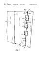
- FIG. 1 is a perspective view of a pole system for displaying picture frames according to the preferred embodiment of the present invention and shown in the environment of a systems furniture workstation or cubicle;
- FIG. 2 is a side view of the pole, sliding elements and frame components shown in FIG. 1, partially in section, the pole being a two piece telescoping pole held on a systems furniture panel by the resilient forces of an elastic inner cord acting on upper and lower mounting brackets;
- FIG. 2A is an enlarged side sectional view of the upper and lower ends of the pole system for displaying picture frames and showing the elastic cord, finial and one of the single sliding elements;
- FIG. 3 is a perspective view of a plate sliding element used in the system of FIG. 1;
- FIG. 4 is a perspective view of an alternative form of sliding element useful with the pole display system of the present invention.
- FIG. 4A is a partial schematic view of the sliding element of FIG. 4 displayed on a cylindrical pole
- FIG. 5 is a partial schematic view of the rear of a picture frame showing one type of mounting bracket.
- FIG. 6 is an alternate embodiment of the present invention in which a pole is held in a vertical orientation between the ceiling and the floor of a room and wherein a sliding element is deployed on the rod in the same manner as shown in FIG. 1 .
- the rod comprises a plurality of telescoping sections held together by the resilient forces of an elastic cord.
- the pole can be a single section and may be made in profiles other than circular in cross-section.
- the resiliency of the cord is particularly well suited for embodiments where a clamping force applied to mounting brackets may be desired, such as the top and bottom brackets used with systems furniture office panels.
- a pole may be provided with threaded openings at its upper and lower ends for receiving bolts extending from the center of bottom and top mounting plates. By suitable rotation of the plates, the distance between the plates will change and the pole can be secured in a vertical position between the floor and ceiling of a room.
- the materials of construction are also widely variable.
- Metal poles, or poles made from plastic resins are preferred, but wooden poles may also be used.
- the poles may be hollow or solid.
- sliding elements are illustrated in the following sections, flat plates and collars. Other types of sliding elements could also be employed, such as clothes pin type clips.
- the picture frame backing can also be any of those known to the art which are capable of cooperation with a hook on a the sliding element to hold the picture frame in a desired position.
- Applicant prefers to use the sawtooth brackets commonly found on the back of picture frames, but wires or tabs can also be used.
- the number of picture frames which may be provided on a single pole can vary widely and will depend in large part on the particular environment and on the size of the picture frames which will be used.
- mounting brackets are attached is not, in and of itself, part of the present invention. They may be welded or otherwise permanently attached to the rod or may be coupled thereto through openings, shoulders on the clips or rods, threaded fasteners on either side of the clip opening and the like. It will also be noted that finials are used in an illustrated embodiment, primarily for decorative purposes, and they may be of the type which include a collar which extends over the end of the pole or they may have a plug which is inserted into the end of the pole.
- an office furniture panel 10 is shown to include a top edge 12 , a bottom edge 14 , an outer edge 16 and an inner edge 18 coupled to an adjoining office panel 20 .
- the pole system for displaying picture frames 25 is shown attached to the upper edge 12 and the bottom edge 14 near the outer edge 16 and to include three picture frames 26 , 27 and 28 . Greater detail concerning the preferred embodiment is found in FIG. 2, a side view of the pole system for displaying picture frames 25 .
- a pole 30 is comprised of a first lower section 31 and a second upper section 32 , the upper end of section 31 telescoping into the lower end of section 32 .
- Picture frame 28 has been removed from this drawing for purposes of illustrating certain components.
- the pole system for displaying picture frames 26 , 27 and 28 also includes an upper mounting bracket 35 and a lower mounting bracket 37 .
- Mounting bracket 35 includes a generally U-shaped portion 40 which has one leg which extends a greater distance than the other. The width of the U-shaped portion 40 is sufficient to pass over the top edge 12 of the panel 10 .
- an outwardly extending plate 43 is provided which in turn includes an up turned bend 45 .
- a hole is provided through the plate 43 .
- the lower mounting bracket 37 is similarly shaped and includes a U-shaped portion 38 having a longer leg portion 44 , an outwardly extending plate 46 and a down turned bend 47 .
- FIG. 2 shows that the lower portion 31 of pole 30 telescopes inside of section 32 , thereby permitting the pole to be stored, packaged and shipped in one-half the length which would be required if the pole 30 were solid.
- an elastic cord 52 extends the length of pole 30 and is attached at the upper end of the pole to a elastic cord hook 54 and at the bottom of the pole to an elastic cord hook 55 .
- the cord would be relaxed when the two pole sections 31 and 32 are entirely nested and has sufficient resiliency to allow for extension of sections 31 and 32 for more than the full height of the office panel 10 .
- the upper end of lower pole section 31 is identified by reference numeral 33 .
- Finials 60 and 61 are best illustrated in the enlarged view FIG. 2A showing the upper and lower portions of the pole system for displaying picture frames 25 .
- Each of the finials 60 and 61 include a decorative ball 64 and a collar 65 which extends about the respective ends of the pole sections 31 and 32 . They may be adhered in place with an adhesive or with a set screw or the like.
- FIG. 2A also illustrates the attachment of a small hook 68 to the respective ends of the cord 52 and a post 69 to which the hook 68 is attached in a permanent manner.
- pole may be attached to an office panel 10 .
- the pole sections 31 and 32 are pulled apart so that one of the brackets 35 or 37 is placed over an edge of the panel 10 .
- the other end of the pole 30 is then pulled further away by an amount sufficient to have the U-shaped pocket of that end extend over the opposite edge, at which point the elastic cord is allowed to perform its function and draw the two brackets together to hold pole 30 in place under a tension load.
- FIG. 2 also illustrates three sliding elements 75 , 76 and 77 deployed at approximately equal distances along the length of pole 30 .
- a sliding element 75 is shown in FIG. 3 to include a generally elongate plate 80 made from a resilient material and including a first opening 81 adjacent a first end and a second opening 82 adjacent the second end. Openings 81 and 82 are just slightly larger than the size of the pole 30 with which they will be used.
- Sliding element 75 also includes a hook 85 at its approximate mid-point, the shape and orientation of the hook is best appreciated by reference to FIG. 2 A.
- Sliding element 75 is coupled to pole 30 by bending plate 80 so that a first one of hole openings 81 and 82 can be placed over the pole, followed by the second opening.
- the plate 80 will, when released, attempt to return to its original flat condition, thereby locking the sliding element 75 at the location where the bending pressure is released.
- the sliding element 75 may be easily moved along the pole 30 by grasping the two ends of plate 80 , urging them slightly toward one another in the curved configuration illustrated, sliding the element 75 to a new location and again releasing the bending forces on the plate 80 .
- the hook 85 of the respective sliding elements 75 , 76 and 77 may each be inserted into a receiving area on the back of the frames, preferably using a sawtooth bracket, which is well-known and which does not, in and of itself, form part of the present invention.
- a sawtooth bracket is illustrated in a partial drawing, FIG. 5 .
- a sawtooth bracket 90 is for purposes of illustration and a wire extending across the back of the picture frame could be placed over the hooks 85 , or if a tab with holes was provided in the back of the frame, the hole could be placed over the hook, as would be well known by those familiar with the picture frame art.
- FIG. 4 An alternate form of sliding element is shown in FIG. 4, wherein a cylindrical sliding element 93 is provided on one side with a hook 94 and with a set screw 95 on the opposite side.
- the set screw is preferably hand manipulated and extends through a threaded opening 96 in the wall of cylindrical sliding element 93 so that the cylindrical sliding element 93 may be locked in any desired location along pole 30 .
- FIG. 4A is a simplified, schematic showing a portion of pole section 32 extending through the cylindrical sliding element 93 and locked in place by the set screw 95 .
- FIG. 6 Another embodiment of the invention is shown in partial form in FIG. 6 .
- This view is provided to illustrate another way in which a pole 130 could be secured in a vertical position.
- a threaded washer is provided in each end of pole 130 , an upper washer 132 and a lower washer 134 .
- a pair of plates 135 and 137 having a diameter significantly greater than that of the pole 130 are also provided, and each includes a threaded bolt 138 extending perpendicularly from the center thereof.
- the thread configuration of the washers 132 , 134 and rods 138 are selected to allow various lengths of the bolt 138 to be threaded into the hollow interior of the pole 130 . This will allow the distance between the respective plates 135 and 137 to change.
- the plates 135 and 137 can be rotated in appropriate directions to secure pole 130 into placed under a compressive load.
- the sliding elements are not shown in FIG. 6, but they could be of either of the types described above in connection with the other illustrated embodiments, or other sliding elements which can be moved along a pole and which can be secured in place easily and quickly.
Landscapes
- Physics & Mathematics (AREA)
- General Physics & Mathematics (AREA)
- Engineering & Computer Science (AREA)
- Theoretical Computer Science (AREA)
- Mirrors, Picture Frames, Photograph Stands, And Related Fastening Devices (AREA)
Abstract
Description
Claims (17)
Priority Applications (1)
| Application Number | Priority Date | Filing Date | Title |
|---|---|---|---|
| US09/305,632 US6212810B1 (en) | 1999-05-05 | 1999-05-05 | Pole system for displaying picture frames |
Applications Claiming Priority (1)
| Application Number | Priority Date | Filing Date | Title |
|---|---|---|---|
| US09/305,632 US6212810B1 (en) | 1999-05-05 | 1999-05-05 | Pole system for displaying picture frames |
Publications (1)
| Publication Number | Publication Date |
|---|---|
| US6212810B1 true US6212810B1 (en) | 2001-04-10 |
Family
ID=23181632
Family Applications (1)
| Application Number | Title | Priority Date | Filing Date |
|---|---|---|---|
| US09/305,632 Expired - Fee Related US6212810B1 (en) | 1999-05-05 | 1999-05-05 | Pole system for displaying picture frames |
Country Status (1)
| Country | Link |
|---|---|
| US (1) | US6212810B1 (en) |
Cited By (20)
| Publication number | Priority date | Publication date | Assignee | Title |
|---|---|---|---|---|
| US20030201376A1 (en) * | 2002-04-29 | 2003-10-30 | Colin Knight | Devices and method for hanging a display board |
| US20040026593A1 (en) * | 2002-04-26 | 2004-02-12 | Fay H. Peter | Picture hanging system |
| US20040221501A1 (en) * | 2003-05-08 | 2004-11-11 | Adesso Inc. | Picture frame system with telescoping support |
| US6820853B1 (en) | 2003-03-26 | 2004-11-23 | Dubarry Suzanne | Adjustable wall display |
| US20050081472A1 (en) * | 2003-10-21 | 2005-04-21 | Moore Diane P. | Removable indoor supporting structure |
| US20050223611A1 (en) * | 2004-04-08 | 2005-10-13 | Montecito Research | Picture frame assembly |
| US20050236347A1 (en) * | 2004-04-21 | 2005-10-27 | Acco Brands, Inc. | Display system |
| US20060250347A1 (en) * | 2004-01-08 | 2006-11-09 | Bell'o International, L.L.C. | Flat panel display mounting system |
| US20070107284A1 (en) * | 2005-11-15 | 2007-05-17 | Yvan Lamothe | Message holder |
| US20080030939A1 (en) * | 2006-08-07 | 2008-02-07 | Peerless Industries, Inc. | Mounting display |
| US20080168692A1 (en) * | 2007-01-11 | 2008-07-17 | Scholl Margaret C | Chair rail picture frame |
| US20090045315A1 (en) * | 2007-08-14 | 2009-02-19 | Harralson Benjamin S | Picture hanging position finder and wall marking device |
| US20090218470A1 (en) * | 2006-12-13 | 2009-09-03 | Snap Gallery, Llc | System for displaying photographs |
| GB2464380A (en) * | 2009-10-06 | 2010-04-21 | Richard Peter Salmon | Picture frame hanging pole structure with offset |
| US20160192513A1 (en) * | 2011-10-21 | 2016-06-30 | Keith van der Walde | Suspended Segmented Display Array |
| US10334973B2 (en) * | 2017-06-08 | 2019-07-02 | Abk Innovations Llc | Adjustable and mountable gallery device |
| CN109982615A (en) * | 2016-11-22 | 2019-07-05 | 福特全球技术公司 | Multipurpose storage and fixing solution |
| US10646059B1 (en) * | 2017-01-28 | 2020-05-12 | Keith van der Walde | Suspended segmented display array with low visibility hardware |
| CN113509033A (en) * | 2021-04-26 | 2021-10-19 | 北京建院装饰工程设计有限公司 | Mounting structure of rotatable mirror |
| USD998367S1 (en) | 2017-06-08 | 2023-09-12 | Abk Innovations Llc | Gallery device |
Citations (17)
| Publication number | Priority date | Publication date | Assignee | Title |
|---|---|---|---|---|
| US1196936A (en) * | 1912-11-23 | 1916-09-05 | John Louis Elsass | Support for picture-frames. |
| US1290809A (en) * | 1917-10-25 | 1919-01-07 | Florence B Truax | Portable irrigating-stand. |
| US1423612A (en) * | 1919-05-05 | 1922-07-25 | Harold H Jewett | Camp utensil |
| US3188028A (en) * | 1962-03-20 | 1965-06-08 | Bull Dog Lock Company | Adjustable hanging bracket |
| US3285549A (en) * | 1964-12-01 | 1966-11-15 | Cook Roger Allen | Hanger for paintings and the like |
| US3317168A (en) * | 1964-09-08 | 1967-05-02 | George R Ziph | Object-supporting standard and ground anchor therefor |
| US3592289A (en) * | 1968-09-06 | 1971-07-13 | Conwed Corp | Freestanding acoustical space divider |
| US3635352A (en) * | 1969-07-11 | 1972-01-18 | Otis Brooks | Space saver drawing holder |
| US3638894A (en) * | 1970-06-22 | 1972-02-01 | Nicolas W Leutenegger | Temporary sign brackets |
| US4508300A (en) * | 1982-09-23 | 1985-04-02 | Wolff Wire Corporation | Support bracket for accessory beam |
| US4549713A (en) * | 1983-10-28 | 1985-10-29 | Magadini Charles R | Vertically adjustable hangers for pictures, and the like |
| US4561617A (en) * | 1984-07-06 | 1985-12-31 | Hafner William E | Support device for displaying objects |
| US4976409A (en) * | 1990-03-12 | 1990-12-11 | Willy Hansen | Adjustable picture hanger |
| JPH0467816A (en) * | 1990-07-06 | 1992-03-03 | Kiyoto Nishitani | Picture frame hanger |
| US5342014A (en) * | 1992-09-04 | 1994-08-30 | Wilson Malcolm A | Display system |
| US5452140A (en) * | 1994-07-14 | 1995-09-19 | Kody; Louise B. | Mirror holder |
| US5560418A (en) * | 1993-04-02 | 1996-10-01 | Advantage Office Systems, L.L.C. | Attachment bar for partition panel |
-
1999
- 1999-05-05 US US09/305,632 patent/US6212810B1/en not_active Expired - Fee Related
Patent Citations (17)
| Publication number | Priority date | Publication date | Assignee | Title |
|---|---|---|---|---|
| US1196936A (en) * | 1912-11-23 | 1916-09-05 | John Louis Elsass | Support for picture-frames. |
| US1290809A (en) * | 1917-10-25 | 1919-01-07 | Florence B Truax | Portable irrigating-stand. |
| US1423612A (en) * | 1919-05-05 | 1922-07-25 | Harold H Jewett | Camp utensil |
| US3188028A (en) * | 1962-03-20 | 1965-06-08 | Bull Dog Lock Company | Adjustable hanging bracket |
| US3317168A (en) * | 1964-09-08 | 1967-05-02 | George R Ziph | Object-supporting standard and ground anchor therefor |
| US3285549A (en) * | 1964-12-01 | 1966-11-15 | Cook Roger Allen | Hanger for paintings and the like |
| US3592289A (en) * | 1968-09-06 | 1971-07-13 | Conwed Corp | Freestanding acoustical space divider |
| US3635352A (en) * | 1969-07-11 | 1972-01-18 | Otis Brooks | Space saver drawing holder |
| US3638894A (en) * | 1970-06-22 | 1972-02-01 | Nicolas W Leutenegger | Temporary sign brackets |
| US4508300A (en) * | 1982-09-23 | 1985-04-02 | Wolff Wire Corporation | Support bracket for accessory beam |
| US4549713A (en) * | 1983-10-28 | 1985-10-29 | Magadini Charles R | Vertically adjustable hangers for pictures, and the like |
| US4561617A (en) * | 1984-07-06 | 1985-12-31 | Hafner William E | Support device for displaying objects |
| US4976409A (en) * | 1990-03-12 | 1990-12-11 | Willy Hansen | Adjustable picture hanger |
| JPH0467816A (en) * | 1990-07-06 | 1992-03-03 | Kiyoto Nishitani | Picture frame hanger |
| US5342014A (en) * | 1992-09-04 | 1994-08-30 | Wilson Malcolm A | Display system |
| US5560418A (en) * | 1993-04-02 | 1996-10-01 | Advantage Office Systems, L.L.C. | Attachment bar for partition panel |
| US5452140A (en) * | 1994-07-14 | 1995-09-19 | Kody; Louise B. | Mirror holder |
Non-Patent Citations (1)
| Title |
|---|
| Home Accents Today, Dec. 1998, p. 7 (photo display). |
Cited By (30)
| Publication number | Priority date | Publication date | Assignee | Title |
|---|---|---|---|---|
| US20040026593A1 (en) * | 2002-04-26 | 2004-02-12 | Fay H. Peter | Picture hanging system |
| US7147196B2 (en) | 2002-04-29 | 2006-12-12 | General Binding Corporation | Devices and method for hanging a display board |
| US20030201376A1 (en) * | 2002-04-29 | 2003-10-30 | Colin Knight | Devices and method for hanging a display board |
| US6820853B1 (en) | 2003-03-26 | 2004-11-23 | Dubarry Suzanne | Adjustable wall display |
| US20040221501A1 (en) * | 2003-05-08 | 2004-11-11 | Adesso Inc. | Picture frame system with telescoping support |
| US20050081472A1 (en) * | 2003-10-21 | 2005-04-21 | Moore Diane P. | Removable indoor supporting structure |
| US20060250347A1 (en) * | 2004-01-08 | 2006-11-09 | Bell'o International, L.L.C. | Flat panel display mounting system |
| US20050223611A1 (en) * | 2004-04-08 | 2005-10-13 | Montecito Research | Picture frame assembly |
| US20050236347A1 (en) * | 2004-04-21 | 2005-10-27 | Acco Brands, Inc. | Display system |
| US20070107284A1 (en) * | 2005-11-15 | 2007-05-17 | Yvan Lamothe | Message holder |
| US20080030939A1 (en) * | 2006-08-07 | 2008-02-07 | Peerless Industries, Inc. | Mounting display |
| US7934331B2 (en) | 2006-12-13 | 2011-05-03 | Snap Gallery, Llc | System for displaying photographs |
| US20090218470A1 (en) * | 2006-12-13 | 2009-09-03 | Snap Gallery, Llc | System for displaying photographs |
| US7610708B2 (en) | 2007-01-11 | 2009-11-03 | Scholl Margaret C | Chair rail picture frame |
| US20080168692A1 (en) * | 2007-01-11 | 2008-07-17 | Scholl Margaret C | Chair rail picture frame |
| US20090045315A1 (en) * | 2007-08-14 | 2009-02-19 | Harralson Benjamin S | Picture hanging position finder and wall marking device |
| US7954782B2 (en) * | 2007-08-14 | 2011-06-07 | Benjamin Simpson Harralson | Picture hanging position finder and wall marking device |
| GB2464380A (en) * | 2009-10-06 | 2010-04-21 | Richard Peter Salmon | Picture frame hanging pole structure with offset |
| GB2464380B (en) * | 2009-10-06 | 2010-09-15 | Richard Peter Salmon | Apparatus for hanging a picture frame or the like |
| US20160192513A1 (en) * | 2011-10-21 | 2016-06-30 | Keith van der Walde | Suspended Segmented Display Array |
| US9723732B2 (en) * | 2011-10-21 | 2017-08-01 | Keith van der Walde | Suspended segmented display array |
| CN109982615A (en) * | 2016-11-22 | 2019-07-05 | 福特全球技术公司 | Multipurpose storage and fixing solution |
| US20190376638A1 (en) * | 2016-11-22 | 2019-12-12 | Ford Global Technologies, Llc | Multiuse storage and holding solution |
| US11168829B2 (en) * | 2016-11-22 | 2021-11-09 | Ford Global Technologies, Llc | Multiuse storage and holding solution |
| CN109982615B (en) * | 2016-11-22 | 2022-03-08 | 福特全球技术公司 | Multipurpose storage and retention solution |
| US10646059B1 (en) * | 2017-01-28 | 2020-05-12 | Keith van der Walde | Suspended segmented display array with low visibility hardware |
| US10334973B2 (en) * | 2017-06-08 | 2019-07-02 | Abk Innovations Llc | Adjustable and mountable gallery device |
| US10869564B2 (en) | 2017-06-08 | 2020-12-22 | Abk Innovations Llc | Adjustable and mountable gallery device |
| USD998367S1 (en) | 2017-06-08 | 2023-09-12 | Abk Innovations Llc | Gallery device |
| CN113509033A (en) * | 2021-04-26 | 2021-10-19 | 北京建院装饰工程设计有限公司 | Mounting structure of rotatable mirror |
Similar Documents
| Publication | Publication Date | Title |
|---|---|---|
| US6212810B1 (en) | Pole system for displaying picture frames | |
| US4026508A (en) | Hanger bracket | |
| US6227506B1 (en) | Bracket assembly | |
| US6053468A (en) | Frame support system | |
| US6935518B2 (en) | System and apparatus for holding an item in storage | |
| US20030038222A1 (en) | Picture hanger | |
| US6443318B1 (en) | Structural support system having free-standing vertical standards | |
| EP1442683A1 (en) | Commodity display device | |
| US5186341A (en) | Support system for hanging items | |
| US20110185558A1 (en) | Systems and Methods for Displaying Backer Material | |
| US3692265A (en) | Corner mountable brackets | |
| US20050001136A1 (en) | Picture hanging system | |
| CN112690679A (en) | Suspended shelf system | |
| US6182841B1 (en) | Display system for lamp shades | |
| US4561617A (en) | Support device for displaying objects | |
| US5924246A (en) | Hanger clip system for use with suspended ceilings | |
| US9797550B1 (en) | Apparatus for suspending items from a mantel or shelf | |
| JP2005525857A (en) | Curtain hanging device and method for hanging curtain | |
| US11533996B2 (en) | Apparatus for securing accessories and leveling objects to wire shelving | |
| US20220151416A1 (en) | Hanging bracket | |
| WO1994024440A1 (en) | A connector for a shopfitting system | |
| KR101322684B1 (en) | A hanging ring using wire | |
| JP3205610U (en) | Perforated board for article suspension and article mounting structure using the same | |
| JPH0919348A (en) | Hanger rail system | |
| JPH0340200Y2 (en) |
Legal Events
| Date | Code | Title | Description |
|---|---|---|---|
| AS | Assignment |
Owner name: INTERCRAFT COMPANY, ILLINOIS Free format text: ASSIGNMENT OF ASSIGNORS INTEREST;ASSIGNOR:JONES, JOSEPH W.;REEL/FRAME:009943/0137 Effective date: 19990430 |
|
| REMI | Maintenance fee reminder mailed | ||
| LAPS | Lapse for failure to pay maintenance fees | ||
| LAPS | Lapse for failure to pay maintenance fees |
Free format text: PATENT EXPIRED FOR FAILURE TO PAY MAINTENANCE FEES (ORIGINAL EVENT CODE: EXP.); ENTITY STATUS OF PATENT OWNER: LARGE ENTITY |
|
| STCH | Information on status: patent discontinuation |
Free format text: PATENT EXPIRED DUE TO NONPAYMENT OF MAINTENANCE FEES UNDER 37 CFR 1.362 |
|
| FP | Lapsed due to failure to pay maintenance fee |
Effective date: 20050410 |
|
| AS | Assignment |
Owner name: BURNES HOME ACCENTS, LLC, TEXAS Free format text: NUNC PRO TUNC ASSIGNMENT;ASSIGNOR:INTERCRAFT COMPANY;REEL/FRAME:018590/0699 Effective date: 20061130 |
|
| AS | Assignment |
Owner name: BANK OF AMERICA, N.A.,GEORGIA Free format text: SECURITY AGREEMENT;ASSIGNOR:BURNES HOME ACCENTS, LLC;REEL/FRAME:018961/0933 Effective date: 20060602 Owner name: BANK OF AMERICA, N.A., GEORGIA Free format text: SECURITY AGREEMENT;ASSIGNOR:BURNES HOME ACCENTS, LLC;REEL/FRAME:018961/0933 Effective date: 20060602 |
|
| AS | Assignment |
Owner name: BURNES HOME ACCENTS, LLC, GEORGIA Free format text: RELEASE BY SECURED PARTY;ASSIGNOR:BANK OF AMERICA, N.A.;REEL/FRAME:020227/0723 Effective date: 20071207 Owner name: BURNES HOME ACCENTS, LLC,GEORGIA Free format text: RELEASE BY SECURED PARTY;ASSIGNOR:BANK OF AMERICA, N.A.;REEL/FRAME:020227/0723 Effective date: 20071207 |
|
| AS | Assignment |
Owner name: BANK OF AMERICA, N.A., GEORGIA Free format text: SECURITY AGREEMENT;ASSIGNOR:BURNES HOME ACCENTS, LLC;REEL/FRAME:026047/0555 Effective date: 20110329 |
|
| AS | Assignment |
Owner name: BURNES HOME ACCENTS, LLC, GEORGIA Free format text: ASSIGNMENT OF ASSIGNORS INTEREST;ASSIGNOR:BANK OF AMERICA, N.A.;REEL/FRAME:028257/0833 Effective date: 20120521 |