US6214486B1 - Fuel cell and method of controlling same - Google Patents
Fuel cell and method of controlling same Download PDFInfo
- Publication number
- US6214486B1 US6214486B1 US09/484,765 US48476500A US6214486B1 US 6214486 B1 US6214486 B1 US 6214486B1 US 48476500 A US48476500 A US 48476500A US 6214486 B1 US6214486 B1 US 6214486B1
- Authority
- US
- United States
- Prior art keywords
- cooling medium
- oxygen containing
- fuel cell
- containing gas
- hole
- Prior art date
- Legal status (The legal status is an assumption and is not a legal conclusion. Google has not performed a legal analysis and makes no representation as to the accuracy of the status listed.)
- Expired - Lifetime
Links
Images


Classifications
-
- H—ELECTRICITY
- H01—ELECTRIC ELEMENTS
- H01M—PROCESSES OR MEANS, e.g. BATTERIES, FOR THE DIRECT CONVERSION OF CHEMICAL ENERGY INTO ELECTRICAL ENERGY
- H01M8/00—Fuel cells; Manufacture thereof
- H01M8/02—Details
- H01M8/0202—Collectors; Separators, e.g. bipolar separators; Interconnectors
- H01M8/0204—Non-porous and characterised by the material
- H01M8/0223—Composites
- H01M8/0228—Composites in the form of layered or coated products
-
- H—ELECTRICITY
- H01—ELECTRIC ELEMENTS
- H01M—PROCESSES OR MEANS, e.g. BATTERIES, FOR THE DIRECT CONVERSION OF CHEMICAL ENERGY INTO ELECTRICAL ENERGY
- H01M8/00—Fuel cells; Manufacture thereof
- H01M8/02—Details
- H01M8/0202—Collectors; Separators, e.g. bipolar separators; Interconnectors
- H01M8/023—Porous and characterised by the material
- H01M8/0234—Carbonaceous material
-
- H—ELECTRICITY
- H01—ELECTRIC ELEMENTS
- H01M—PROCESSES OR MEANS, e.g. BATTERIES, FOR THE DIRECT CONVERSION OF CHEMICAL ENERGY INTO ELECTRICAL ENERGY
- H01M8/00—Fuel cells; Manufacture thereof
- H01M8/02—Details
- H01M8/0202—Collectors; Separators, e.g. bipolar separators; Interconnectors
- H01M8/023—Porous and characterised by the material
- H01M8/0241—Composites
- H01M8/0245—Composites in the form of layered or coated products
-
- H—ELECTRICITY
- H01—ELECTRIC ELEMENTS
- H01M—PROCESSES OR MEANS, e.g. BATTERIES, FOR THE DIRECT CONVERSION OF CHEMICAL ENERGY INTO ELECTRICAL ENERGY
- H01M8/00—Fuel cells; Manufacture thereof
- H01M8/02—Details
- H01M8/0202—Collectors; Separators, e.g. bipolar separators; Interconnectors
- H01M8/0258—Collectors; Separators, e.g. bipolar separators; Interconnectors characterised by the configuration of channels, e.g. by the flow field of the reactant or coolant
- H01M8/0263—Collectors; Separators, e.g. bipolar separators; Interconnectors characterised by the configuration of channels, e.g. by the flow field of the reactant or coolant having meandering or serpentine paths
-
- H—ELECTRICITY
- H01—ELECTRIC ELEMENTS
- H01M—PROCESSES OR MEANS, e.g. BATTERIES, FOR THE DIRECT CONVERSION OF CHEMICAL ENERGY INTO ELECTRICAL ENERGY
- H01M8/00—Fuel cells; Manufacture thereof
- H01M8/02—Details
- H01M8/0202—Collectors; Separators, e.g. bipolar separators; Interconnectors
- H01M8/0267—Collectors; Separators, e.g. bipolar separators; Interconnectors having heating or cooling means, e.g. heaters or coolant flow channels
-
- H—ELECTRICITY
- H01—ELECTRIC ELEMENTS
- H01M—PROCESSES OR MEANS, e.g. BATTERIES, FOR THE DIRECT CONVERSION OF CHEMICAL ENERGY INTO ELECTRICAL ENERGY
- H01M8/00—Fuel cells; Manufacture thereof
- H01M8/02—Details
- H01M8/0271—Sealing or supporting means around electrodes, matrices or membranes
- H01M8/0273—Sealing or supporting means around electrodes, matrices or membranes with sealing or supporting means in the form of a frame
-
- H—ELECTRICITY
- H01—ELECTRIC ELEMENTS
- H01M—PROCESSES OR MEANS, e.g. BATTERIES, FOR THE DIRECT CONVERSION OF CHEMICAL ENERGY INTO ELECTRICAL ENERGY
- H01M8/00—Fuel cells; Manufacture thereof
- H01M8/04—Auxiliary arrangements, e.g. for control of pressure or for circulation of fluids
- H01M8/04007—Auxiliary arrangements, e.g. for control of pressure or for circulation of fluids related to heat exchange
- H01M8/04029—Heat exchange using liquids
-
- H—ELECTRICITY
- H01—ELECTRIC ELEMENTS
- H01M—PROCESSES OR MEANS, e.g. BATTERIES, FOR THE DIRECT CONVERSION OF CHEMICAL ENERGY INTO ELECTRICAL ENERGY
- H01M8/00—Fuel cells; Manufacture thereof
- H01M8/04—Auxiliary arrangements, e.g. for control of pressure or for circulation of fluids
- H01M8/04007—Auxiliary arrangements, e.g. for control of pressure or for circulation of fluids related to heat exchange
- H01M8/04067—Heat exchange or temperature measuring elements, thermal insulation, e.g. heat pipes, heat pumps, fins
- H01M8/04074—Heat exchange unit structures specially adapted for fuel cell
-
- H—ELECTRICITY
- H01—ELECTRIC ELEMENTS
- H01M—PROCESSES OR MEANS, e.g. BATTERIES, FOR THE DIRECT CONVERSION OF CHEMICAL ENERGY INTO ELECTRICAL ENERGY
- H01M8/00—Fuel cells; Manufacture thereof
- H01M8/24—Grouping of fuel cells, e.g. stacking of fuel cells
- H01M8/241—Grouping of fuel cells, e.g. stacking of fuel cells with solid or matrix-supported electrolytes
- H01M8/242—Grouping of fuel cells, e.g. stacking of fuel cells with solid or matrix-supported electrolytes comprising framed electrodes or intermediary frame-like gaskets
-
- H—ELECTRICITY
- H01—ELECTRIC ELEMENTS
- H01M—PROCESSES OR MEANS, e.g. BATTERIES, FOR THE DIRECT CONVERSION OF CHEMICAL ENERGY INTO ELECTRICAL ENERGY
- H01M8/00—Fuel cells; Manufacture thereof
- H01M8/24—Grouping of fuel cells, e.g. stacking of fuel cells
- H01M8/2465—Details of groupings of fuel cells
- H01M8/2483—Details of groupings of fuel cells characterised by internal manifolds
-
- H—ELECTRICITY
- H01—ELECTRIC ELEMENTS
- H01M—PROCESSES OR MEANS, e.g. BATTERIES, FOR THE DIRECT CONVERSION OF CHEMICAL ENERGY INTO ELECTRICAL ENERGY
- H01M2300/00—Electrolytes
- H01M2300/0017—Non-aqueous electrolytes
- H01M2300/0065—Solid electrolytes
- H01M2300/0082—Organic polymers
-
- H—ELECTRICITY
- H01—ELECTRIC ELEMENTS
- H01M—PROCESSES OR MEANS, e.g. BATTERIES, FOR THE DIRECT CONVERSION OF CHEMICAL ENERGY INTO ELECTRICAL ENERGY
- H01M8/00—Fuel cells; Manufacture thereof
- H01M8/02—Details
- H01M8/0202—Collectors; Separators, e.g. bipolar separators; Interconnectors
- H01M8/0204—Non-porous and characterised by the material
- H01M8/0206—Metals or alloys
- H01M8/0208—Alloys
- H01M8/021—Alloys based on iron
-
- H—ELECTRICITY
- H01—ELECTRIC ELEMENTS
- H01M—PROCESSES OR MEANS, e.g. BATTERIES, FOR THE DIRECT CONVERSION OF CHEMICAL ENERGY INTO ELECTRICAL ENERGY
- H01M8/00—Fuel cells; Manufacture thereof
- H01M8/02—Details
- H01M8/0202—Collectors; Separators, e.g. bipolar separators; Interconnectors
- H01M8/0204—Non-porous and characterised by the material
- H01M8/0213—Gas-impermeable carbon-containing materials
-
- H—ELECTRICITY
- H01—ELECTRIC ELEMENTS
- H01M—PROCESSES OR MEANS, e.g. BATTERIES, FOR THE DIRECT CONVERSION OF CHEMICAL ENERGY INTO ELECTRICAL ENERGY
- H01M8/00—Fuel cells; Manufacture thereof
- H01M8/02—Details
- H01M8/0202—Collectors; Separators, e.g. bipolar separators; Interconnectors
- H01M8/0204—Non-porous and characterised by the material
- H01M8/0223—Composites
- H01M8/0226—Composites in the form of mixtures
-
- H—ELECTRICITY
- H01—ELECTRIC ELEMENTS
- H01M—PROCESSES OR MEANS, e.g. BATTERIES, FOR THE DIRECT CONVERSION OF CHEMICAL ENERGY INTO ELECTRICAL ENERGY
- H01M8/00—Fuel cells; Manufacture thereof
- H01M8/02—Details
- H01M8/0202—Collectors; Separators, e.g. bipolar separators; Interconnectors
- H01M8/023—Porous and characterised by the material
- H01M8/0232—Metals or alloys
-
- H—ELECTRICITY
- H01—ELECTRIC ELEMENTS
- H01M—PROCESSES OR MEANS, e.g. BATTERIES, FOR THE DIRECT CONVERSION OF CHEMICAL ENERGY INTO ELECTRICAL ENERGY
- H01M8/00—Fuel cells; Manufacture thereof
- H01M8/02—Details
- H01M8/0202—Collectors; Separators, e.g. bipolar separators; Interconnectors
- H01M8/023—Porous and characterised by the material
- H01M8/0241—Composites
- H01M8/0243—Composites in the form of mixtures
-
- Y—GENERAL TAGGING OF NEW TECHNOLOGICAL DEVELOPMENTS; GENERAL TAGGING OF CROSS-SECTIONAL TECHNOLOGIES SPANNING OVER SEVERAL SECTIONS OF THE IPC; TECHNICAL SUBJECTS COVERED BY FORMER USPC CROSS-REFERENCE ART COLLECTIONS [XRACs] AND DIGESTS
- Y02—TECHNOLOGIES OR APPLICATIONS FOR MITIGATION OR ADAPTATION AGAINST CLIMATE CHANGE
- Y02E—REDUCTION OF GREENHOUSE GAS [GHG] EMISSIONS, RELATED TO ENERGY GENERATION, TRANSMISSION OR DISTRIBUTION
- Y02E60/00—Enabling technologies; Technologies with a potential or indirect contribution to GHG emissions mitigation
- Y02E60/30—Hydrogen technology
- Y02E60/50—Fuel cells
Definitions
- the present invention relates to a fuel cell having a fuel cell structure including an anode electrode and a cathode electrode which sandwich an electrolyte membrane therebetween and separators which sandwich the fuel cell structure therebetween, and a method of controlling the fuel cell.
- Solid polymer electrochemical fuel cells comprise a plurality of unit cells each comprising an electrolyte membrane in the form of an ion exchange membrane and a catalytic electrode and a porous carbon electrode which are disposed one on each side of the electrolyte membrane.
- Hydrogen supplied to the anode of the fuel cell is converted into hydrogen ions on the catalytic electrode, which move through the electrolyte membrane that has been humidified to an appropriate extent toward the cathode of the fuel cell which is made of porous carbon.
- An oxygen containing gas or air is supplied to the cathode electrode to generate water through a reaction between the hydrogen ions and the oxygen on the cathode electrode. Electrons which are generated at this time are led to an external circuit for use as electric energy as a direct current.
- Such a fuel cell is disclosed in Japanese laid-open patent publication No. 6-20713.
- the disclosed fuel cell has parallel grooves defined in the separators for supplying a fuel gas and an oxygen containing gas, respectively, the grooves being directed downwardly in the direction of gravity for draining the collected water in order to enable the solid polymer electrolyte membrane to generate electric energy at a sufficiently high level.
- a fuel cell 4 has a number of fuel cell cells 2 stacked along the direction of gravity, then water droplets are collected in regions (e.g., regions 6 a or 6 b ) where the flow of a fuel gas or an oxygen containing gas that has been humidified, greatly lowering the performance of those fuel cells 2 which are positioned adjacent to the fuel cells 2 including the regions 6 a or 6 b as compared to the other fuel cells 2 .
- regions 6 a or 6 b regions where the flow of a fuel gas or an oxygen containing gas that has been humidified, greatly lowering the performance of those fuel cells 2 which are positioned adjacent to the fuel cells 2 including the regions 6 a or 6 b as compared to the other fuel cells 2 .
- the fuel cell disclosed in Japanese laid-open patent publication No. 6-20713 has such a structure that the fuel gas and the oxygen containing gas flow in directions perpendicular to the direction of gravity along the solid polymer electrolyte membrane, the anode electrode, and the cathode electrode, and cooling water flows perpendicularly to the fuel gas and the oxygen containing gas flow. While this structure is effective to alleviate shortcomings caused by unstable voltages that possibly occur due to generation and elimination of condensed water, it has been confirmed with the disclosed structure that the current density is temporarily increased owing to a temperature rise at the outlets of the fuel cells.
- FIG. 32 of the accompanying drawings when a fuel gas such as a hydrogen containing gas and an oxygen containing gas such as an oxide gas flow in a direction perpendicular to the direction of a cooling water flow with respect to a solid polymer electrolyte membrane 12 that is sandwiched between an anode electrode 8 and a cathode electrode 10 , the temperature of the fuel cell 2 is higher downstream than upstream with respect to the gas flows. Particularly, the temperature is higher at the outlet of the cooling water flow than at the inlet of the cooling water flow.
- a fuel gas such as a hydrogen containing gas and an oxygen containing gas flow in a direction perpendicular to the direction of a cooling water flow with respect to a solid polymer electrolyte membrane 12 that is sandwiched between an anode electrode 8 and a cathode electrode 10
- the temperature of the fuel cell 2 is higher downstream than upstream with respect to the gas flows. Particularly, the temperature is higher at the outlet of the cooling water flow than at the inlet of the cooling water flow.
- each fuel cell 2 suffers a temperature distribution between upstream and downstream portions of the gases, with the result that the voltage generated by the fuel cell 2 suffers a distribution. Accordingly, the output voltage produced by the fuel cell 2 is not stable, shortening the service life of the fuel cell 2 itself. If the fuel cell 4 comprising fuel cells 2 each having a temperature distribution is used as a power source for motor vehicles, then a complex control process will be required to control the running of the motor vehicle.
- a fuel cell comprising a first unit cell, a fuel gas supply means, a cooling plate, an oxygen containing gas supply means, and a second unit cell that are successively stacked in order to remove heat produced upon generation of electric energy, as disclosed in Japanese laid-open patent publication No. 5-190193.
- the cooling plate has cooling water passages defined therein, and the first and second unit cells are cooled by the fuel gas supply means and the oxygen containing gas supply means.
- the cooling efficiency of the surface of the cooling plate which is held against the fuel gas supply means is higher than the cooling efficiency of the surface of the cooling plate which is held against the oxygen containing gas supply means.
- the cooling efficiencies of the anode and cathode electrodes are set to optimum levels by positioning the cooling water passages of the cooling plate closely to the fuel gas supply means, or providing individual cooling water passages respectively in the fuel gas supply means and the oxygen containing gas supply means, or using cooling members having different thermal conductivities respectively with respect to the fuel gas supply means and the oxygen containing gas supply means, or making a fuel gas passage member thinner than an oxygen containing gas passage member.
- the fuel gas supply means, the cooling plate, and the oxygen containing gas supply means are disposed as a separator interposed between the first and second unit cells. Consequently, the separator is made up of many components, has a large thickness, and does not make the fuel cell compact as a whole. Another problem is that the fuel cell is heavy in its entirety because the separator is made up of many components.
- the above separator fails to impart tightening forces directly to the fuel cell structure for structural reasons, and hence the fuel cell needs to have a structure dedicated to produce tightening forces.
- the fuel cell is constructed of an increased number of parts, large in size, and heavy in weight.
- Another object of the present invention is to provide a fuel cell which has anode and cathode electrodes that can be set to optimum cooling efficiencies, respectively, is made up parts that are not increased in number, can be made compact and light.
- Still another object of the present invention is to provide a fuel cell which is simple in structure and can uniformize the temperature of an electric generation section easily and accurately.
- Yet still another object of the present invention is to provide a fuel cell whose electrolyte membrane can directly be humidified, to which desired tightening forces can be imparted, which is simple in structure, and which has many functions.
- a fuel gas and an oxygen containing gas are introduced in the direction of gravity into each of fuel cells, and a cooling medium such as cooling water is introduced in an opposite direction, i.e., against gravity, into separators in the fuel cell. Therefore, the heat generated in a lower portion of the fuel cell is reduced by the cooling medium while its cooling capability is high, for thereby minimizing a temperature distribution in the fuel cell between its upper and lower portions. As a result, the output voltage of each of the fuel cells is stabilized. The minimized temperature distribution is effective to increase the service life of the fuel cell.
- the separator has an anode-side element member held against an anode electrode and a cathode-side element member held against a cathode electrode, with a cooling medium passage defined directly between the anode-side element member and the cathode-side element member. Therefore, the number of components of the separator is reduced.
- the anode-side element member and the cathode-side element member have increased contact area regions on respective surfaces which define the cooling medium passage. Optimum cooling efficiencies for the anode and cathode electrodes can be established simply by changing the shape, etc. of the increased contact area regions.
- Temperature regulating medium passages are defined in a first gas passage for supplying an oxygen containing gas and/or a second gas passage for supplying a fuel gas by a partition, the temperature regulating medium passages being identical in structure to the first gas passage and the second gas passage.
- the oxygen containing gas and/or the fuel gas flows in a direction opposite to the direction in which a temperature regulating medium flows in the temperature regulating medium passages. Therefore, the oxygen containing gas flowing through the first gas passage and a cooling medium flowing through the temperature regulating medium passages flow in opposite directions to each other, so that the efficiency of heat exchange between the oxygen containing gas and the cooling medium is increased for uniformizing the temperature of an electric generation section.
- the temperature of the electric generation section can be uniformized by the fuel gas flowing through the second gas passage and the cooling medium flowing through the temperature regulating medium passages.
- first and second cooling mediums are provided independently in the separator, and desired first and second cooling mediums depending on the anode and cathode electrodes can selectively be introduced into the first and second cooling passages. Consequently, water may be used as the first cooling medium to directly humidify the anode electrode and the fuel gas, and the second cooling medium may be used to apply tightening forces to the cathode electrode. It is also possible to establish cooling efficiencies optimum for the anode and cathode electrodes.
- FIG. 1 is a schematic view illustrative of the principles of a method according to the present invention
- FIG. 2 is an exploded perspective view of a fuel cell according to a first embodiment of the present invention, with respect to which a method according to the present invention is carried out;
- FIG. 3 is a front elevational view showing a bonded state of a solid polymer electrolyte membrane and an electrode of the fuel cell according to the first embodiment
- FIG. 4 is a front elevational view of a gasket of the fuel cell according to the first embodiment
- FIG. 5 is a front elevational view of a first manifold plate of the fuel cell according to the first embodiment
- FIG. 6 is a front elevational view of a second manifold plate of the fuel cell according to the first embodiment
- FIG. 7 is a front elevational view of a surface pressure generating plate of the fuel cell according to the first embodiment
- FIG. 8 is a front elevational view of a separator body of the fuel cell according to the first embodiment
- FIG. 9 is a perspective view of a flow rectifying plate incorporated in the first and second manifold plates of the fuel cell according to the first embodiment
- FIG. 10 is a diagram illustrating that the fuel cell according to the first embodiment is free of a temperature distribution
- FIG. 11 is a perspective view of an integral structure of a manifold plate and a flow rectifying plate of a fuel cell according to a second embodiment of the present invention.
- FIG. 12 is a perspective view of a fuel cell according to a third embodiment of the present invention.
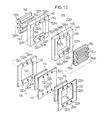
- FIG. 13 is a partial exploded perspective view of the fuel cell according to the third embodiment.
- FIG. 14 is a vertical cross-sectional view of a separator of the fuel cell according to the third embodiment.
- FIG. 15 is a cross-sectional view taken along line XV—XV of FIG. 12;
- FIG. 16 is a perspective view of a fuel cell according to a fourth embodiment of the present invention.
- FIG. 17 is a partial exploded perspective view of the fuel cell according to the fourth embodiment.
- FIG. 18 is a vertical cross-sectional view of the fuel cell according to the fourth embodiment.
- FIG. 19 is a perspective view showing a gas passage and a cooling medium passage which are defined in an oxygen containing gas flow rectifying plate of the fuel cell according to the fourth embodiment;
- FIG. 20 is a perspective view showing a gas passage and a cooling medium passage which are defined in a fuel gas flow rectifying plate of the fuel cell according to the fourth embodiment;
- FIG. 21 is a vertical cross-sectional view of a separator of the fuel cell according to the fourth embodiment.
- FIG. 22 is a perspective view of a fuel cell according to a fifth embodiment of the present invention.
- FIG. 23 is a partial exploded perspective view of the fuel cell according to the fifth embodiment.
- FIG. 24 is a cross-sectional view taken along line XXIV—XXIV of FIG. 22;
- FIG. 25 is a schematic diagram of a supply means for supplying a first cooling medium
- FIG. 26 is a schematic diagram of a pressure control means for controlling the pressure of a second cooling medium
- FIG. 27 is a schematic diagram of another pressure control means for controlling the pressure of the second cooling medium
- FIG. 28 is a cross-sectional view taken along line XXVIII—XXVIII of FIG. 22;
- FIG. 29 is a cross-sectional view taken along line XXIX—XXIX of FIG. 22;
- FIG. 30 is a cross-sectional view taken along line XXX—XXX of FIG. 22;
- FIG. 31 is a schematic diagram showing a stack of conventional fuel cells
- FIG. 32 is a perspective view showing the relationship between the layout of a conventional fuel cell and a temperature distribution thereof.
- FIG. 33 is a perspective view showing the relationship between the layout of a conventional fuel cell and a temperature distribution thereof.
- a fuel cell according to a first embodiment of the present invention basically comprises a horizontal stack of fuel cells 20 .
- Each of the fuel cells 20 includes a fuel cell structure 28 having an anode electrode 26 and a cathode electrode 24 which sandwich a solid polymer electrolyte membrane 22 therebetween.
- the fuel cell structure 28 is described in detail in International laid-open publication WO94-15377, which is incorporated herein by reference.
- the solid polymer electrolyte membrane 22 , the anode electrode 26 , and the cathode electrode 24 are separate from each other. However, they may be of an integral structure.
- the solid polymer electrolyte membrane 22 has an oblong hole 22 a for passing a fuel gas such as a hydrogen containing gas or the like in one direction, a hole 22 b for passing cooling water, and a hole 22 c for passing an oxygen containing gas, the holes 22 a , 22 b , 22 c being defined in an upper portion of the solid polymer electrolyte membrane 22 .
- the solid polymer electrolyte membrane 22 also has a hole 22 d for passing the fuel gas, a hole 22 e for passing the cooling water, and a hole 22 f for passing the oxygen containing gas, the holes 22 d , 22 e , 22 f being defined in a lower portion of the solid polymer electrolyte membrane 22 .
- a first gasket 30 and a second gasket 32 are disposed one on each side of the fuel cell structure 28 .
- the first gasket 30 has a large opening 34 for accommodating the cathode electrode 24 therein, and the second gasket 32 has an opening 36 for accommodating the anode electrode 26 .
- the first gasket 30 and the second gasket 32 have holes 30 a , 30 d and holes 32 a , 32 d , respectively, for passing the fuel gas, holes 30 b , 30 e and holes 32 b , 32 e , respectively, for passing the cooling water, and holes 30 c , 30 f and holes 32 c , 32 f , respectively, for passing the oxygen containing gas, these holes being defined respectively in upper and lower end portions of the first gasket 30 and the second gasket 32 (see FIG. 4 ). Oblong holes defined in sides of the first and second gaskets 30 , 32 serve to reduce the weight thereof.
- a separator 40 against which the first gasket 30 and the second gasket 32 are held and which has a hole for accommodating the anode electrode 26 and the cathode electrode 24 will be described below.
- the separator 40 basically comprises a first manifold plate 42 , a first surface pressure generating plate 44 held against the first manifold plate 42 , a second surface pressure generating plate 46 , a separator body 48 sandwiched between the first surface pressure generating plate 44 and the second surface pressure generating plate 46 , a second manifold plate 50 held against the second surface pressure generating plate 46 .
- the first manifold plate 42 comprises a rectangular flat plate, and has a fuel gas supply recess 42 a defined in an upper right corner thereof for supplying the fuel gas and a cooling water discharge hole 42 b defined therein adjacent to the fuel gas supply recess 42 a for discharging the cooling water.
- the first manifold plate 42 also has an oxygen containing gas supply hole 42 c defined in an upper left corner thereof for supplying the oxygen containing gas.
- the first manifold plate 42 further has a fuel gas discharge recess 42 d defined in a lower left corner thereof for discharging the fuel gas, and a cooling water supply hole 42 e defined therein adjacent to the fuel gas discharge recess 42 d for supplying the cooling water.
- the first manifold plate 42 also has an oxygen containing gas discharge hole 42 f defined in a lower right corner thereof for discharging the oxygen containing gas.
- the fuel gas supply recess 42 a and the fuel gas discharge recess 42 d are held in communication with each other through an opening 43 .
- Oblong holes defined in opposite sides of the first manifold plate 42 and extending vertically serve to reduce the weight of the first manifold plate 42 .
- Circular holes defined in the first manifold plate 42 serve to insert studs or the like therethrough when it is stacked.
- the first manifold plate 42 and the second manifold plate 50 are basically of a symmetrical structure. Therefore, details of the second manifold plate 50 will not be described below.
- the second manifold plate 50 has a fuel gas supply hole 50 a , a cooling water discharge hole 50 b , an oxygen containing gas supply recess 50 c , a fuel gas discharge hole 50 d , a cooling water supply hole 50 e , and an oxygen containing gas discharge recess 50 f .
- the oxygen containing gas supply recess 50 c and the oxygen containing gas discharge recess 50 f are held in communication with each other through an opening 52 .
- the first surface pressure generating plate 44 held against the first manifold plate 42 will be described below with reference to FIG. 7 .
- the second surface pressure generating plate 46 is substantially identical to the first surface pressure generating plate 44 and hence will not be described in detail below.
- the first surface pressure generating plate 44 comprises a flat plate made of an electrically conductive material such as carbon, metal, or the like.
- the first surface pressure generating plate 44 has a fuel gas supply communication hole 44 a defined in an upper right corner thereof and held in communication with the fuel gas supply recess 42 a in the first manifold plate 42 and a cooling water discharge communication hole 44 b defined therein adjacent to the fuel gas supply communication hole 44 a .
- the first surface pressure generating plate 44 also has an oxygen containing gas supply communication hole 44 a defined in an upper left corner thereof and held in communication with the oxygen containing gas supply hole 42 c .
- the first surface pressure generating plate 44 further has a fuel gas discharge communication hole 44 d defined in a lower left corner thereof and held in communication with the fuel gas discharge recess 42 d in the first manifold plate 42 and a cooling water supply communication hole 44 e defined therein adjacent to the fuel gas discharge communication hole 44 d .
- the first surface pressure generating plate 44 also has an oxygen containing gas discharge communication hole 44 f defined in a lower right corner thereof and held in communication with the oxygen containing gas discharge hole 42 f . Remaining oblong holes defined in the first surface pressure generating plate 44 serve to reduce the weight thereof, and circular holes defined in the first surface pressure generating plate 44 serve to insert studs or the like therethrough when the fuel cells 20 are stacked and tightened.
- FIG. 8 shows a third manifold plate, i.e., the separator body 48 .
- the separator body 48 serves to supply the cooling water to cool the fuel cell structure 28 .
- the separator body 48 which is relatively thick, is made of an electrically conductive material such as carbon, metal, or the like.
- the separator body 48 has a fuel gas supply hole 48 a defined in an upper right corner thereof and held in communication with the recess 42 a and the communication hole 44 a .
- the separator body 48 also has a cooling water discharge recess 48 b defined in a substantially central upper portion thereof adjacent to the fuel gas supply hole 48 a and held in communication with the cooling water discharge hole 42 b and the communication hole 44 b .
- the separator body 48 further has an oxygen containing gas supply hole 48 c defined in an upper left corner thereof and held in communication with the oxygen containing gas supply hole 42 c and the communication hole 44 c .
- the separator body 48 also has a hole 48 d defined in a lower left corner thereof and held in communication with the fuel gas discharge recess 42 d and the communication hole 44 d , a cooling water supply recess 48 e directly below the cooling water discharge recess 48 b in FIG. 8, and an oxygen containing gas discharge hole 48 f defined in a lower right corner thereof.
- the recesses 48 b , 48 e communicate with each other through a large opening 62 .
- Cooling water flow rectifying plates 70 , 72 are fitted and fixed in the opening 62 in the separator body 48 .
- the combined thickness of the cooling water flow rectifying plates 70 , 72 is essentially the same as the thickness of the separator body 48 .
- the cooling water flow rectifying plate 70 has a plurality of parallel grooves 70 a extending vertically in FIG. 2 .
- the cooling water flow rectifying plate 72 has a plurality of parallel grooves 72 a .
- the grooves 70 a , 72 a jointly define large cooling water flow rectifying passages which are held in communication with the recesses 48 b , 48 e.
- a fuel gas flow rectifying plate 80 is fitted in the opening 43 in the first manifold plate 42 .
- the fuel gas flow rectifying plate 80 has a flat surface and an opposite surface having a plurality of parallel grooves 80 a defined therein and extending vertically.
- the parallel grooves 80 a provide communication between the fuel gas supply recess 42 a and the fuel gas discharge recess 42 d .
- An oxygen containing gas flow rectifying plate 82 is fitted in the opening 52 in the second manifold plate 50 .
- the oxygen containing gas flow rectifying plate 82 has a flat surface and an opposite surface having a plurality of parallel grooves 82 a defined therein and extending vertically.
- the parallel grooves 82 a provide communication between the oxygen containing gas supply recess 50 c and the oxygen containing gas discharge recess 50 f .
- the first manifold plate 42 , the fuel gas flow rectifying plate 80 , the second manifold plate 50 , and the oxygen containing gas flow rectifying plate 82 have essentially the same thickness.
- the separator body 48 thus constructed is sandwiched by the first surface pressure generating plate 44 and the second surface pressure generating plate 46 , which are in turn sandwiched by the first manifold plate 42 and the second manifold plate 50 .
- the second gasket 32 is held against the first manifold plate 42
- the first gasket 30 is held against the second manifold plate 50 , with the fuel cell structure 28 sandwiched between the gaskets 30 , 32 , thus making up the fuel cell 20 .
- the fuel gas supply hole 22 a in the solid polymer electrolyte membrane 22 , the hole 30 a in the first gasket 30 , the hole 32 a in the second gasket 32 , the recess 42 a in the first manifold plate 42 , the hole 48 a in the separator body 48 , and the hole 50 a in the second manifold plate 50 are kept in communication with each other, and the fuel gas discharge hole, the cooling water discharge hole, the cooling water supply hole, the oxygen containing gas supply hole, and the oxygen containing gas discharge hole are also kept in communication with each other.
- the fuel cell according to the first embodiment which is controlled by a control method according to the present invention is constructed as described above. Operation of the fuel cell will now be described below.
- the fuel cells 20 are stacked together into the fuel cell.
- the stacked fuel cells 20 extend horizontally.
- a hydrogen containing gas preferably, passes as a fuel gas through the recess 42 a in the first manifold plate 42 , the communication hole 44 a in the first surface pressure generating plate 44 , the hole 48 a in the separator body 48 , the communication hole 46 a in the second surface pressure generating plate 46 , the hole 50 a in the second manifold plate 50 , the hole 30 a in the first gasket 30 , the hole 22 a in the solid polymer electrolyte membrane 22 , the hole 32 a in the second gasket 32 , and the recess 42 a in the next first manifold plate 42 .
- the fuel gas passes from the recess 42 a through the grooves 80 a in the flow rectifying plate 80 into the recess 42 d , during which time the fuel gas flowing through the grooves 80 a in the flow rectifying plate 80 reaches the anode electrode 26 .
- the unreacted gas in the recess 42 d passes through the recess 42 d in the first manifold plate 42 , the communication hole 44 d in the first surface pressure generating plate 44 , the hole 48 d in the separator body 48 , the communication hole 46 d in the second surface pressure generating plate 46 , the hole 50 d in the second manifold plate 50 , the hole 30 d in the first gasket 30 , the hole 22 d in the solid polymer electrolyte membrane 22 , the hole 32 d in the second gasket 32 , and the recess 42 d in the next first manifold plate 42 .
- An oxygen containing gas passes through the recess 42 c in the first manifold plate 42 , the communication hole 44 c in the first surface pressure generating plate 44 , the hole 48 c in the separator body 48 , the communication hole 46 c in the second surface pressure generating plate 46 , the hole 50 c in the second manifold plate 50 , the hole 30 c in the first gasket 30 , the hole 22 c in the solid polymer electrolyte membrane 22 , the hole 32 c in the second gasket 32 , and the recess 42 c in the next first manifold plate 42 .
- the oxygen containing gas passes from the recess 50 c through the grooves 82 a in the flow rectifying plate 82 into the recess 50 f , during which time the oxygen containing gas flowing through the grooves 82 a in the flow rectifying plate 82 reaches the cathode electrode 24 .
- the oxygen containing gas in the recess 50 f passes through the recess 42 f in the first manifold plate 42 , the communication hole 44 f in the first surface pressure generating plate 44 , the hole 48 f in the separator body 48 , the communication hole 46 f in the second surface pressure generating plate 46 , the hole 50 f in the second manifold plate 50 , the hole 30 f in the first gasket 30 , the hole 22 f in the solid polymer electrolyte membrane 22 , the hole 32 f in the second gasket 32 , and the recess 42 f in the next first manifold plate 42 .
- Cooling water is supplied in a direction opposite to the fuel gas and the oxygen containing gas. Specifically, the cooling gas having passed through the hole 42 e in the first manifold plate 42 passes through the hole 32 e in the second gasket 32 , the hole 22 e in the solid polymer electrolyte membrane 22 , the hole 30 e in the first gasket 30 , the hole 50 e in the second manifold plate 50 , the communication hole 46 e in the second surface pressure plate 46 , the recess 48 e in the separator body 48 , the communication hole 44 e in the first surface pressure plate 44 , and the hole 42 e in the first manifold plate 42 .
- the cooling water which passes upwardly through the cooling water flow rectifying passage defined between the flow rectifying plates 70 , 72 joined to each other reaches the recess 48 b in the separator body 48 .
- the cooling thus flowing upwardly into the recess 48 b flows through the communication hole 44 b in the first surface pressure plate 44 , the hole 42 b in the first manifold plate 42 , the hole 32 b in the second gasket 32 , the hole 22 b in the solid polymer electrolyte membrane 22 , the hole 30 b in the first gasket 30 , the hole 50 b in the second manifold plate 50 , and the communication hole 46 b in the second surface pressure plate 46 .
- the fuel gas and the oxygen containing gas flow downwardly along the direction of gravity, whereas the cooling water flows upwardly in the separator body 48 . Consequently, as shown in FIG. 10, based on the principles that the cooling water at the lowest temperature cools a region of the fuel cell 20 at the highest temperature, the cooling water forcibly cools the lower portion of the electrolyte membrane 22 where the temperature gradient is high, with a sufficiently high cooling capability that is achieved when the cooling water is introduced into the separator body 48 . Thus, the fuel cell 20 is operated free of a temperature distribution as a whole.
- the overall temperature in the cell plane decreases, removing the heat in the vicinity of the outlet of the cooling water compared with the inlet thereof, so that the temperature of the cell is lowered.
- the cooling water warmed by the heat in the vicinity of the gas outlet increases the temperature of the fuel cell 20 in the vicinity of the gas inlet, substantially reducing the temperature difference in the fuel cell 20 between the gas inlet and the gas outlet. Therefore, it is possible for the fuel cell 20 to operate with a reduced temperature distribution.
- FIG. 11 shows a second embodiment of the present invention with respect to which the method according to the present invention is carried out.
- the first manifold plate 42 and the flow rectifying plate 80 are separate from each other, and similarly the second manifold plate 50 and the flow rectifying plate 82 are separate from each other.
- the first manifold plate 42 and the flow rectifying plate 80 are integral with each other, and the second manifold plate 50 and the flow rectifying plate 82 are integral with each other, thus making up a manifold plate 90 with a flow rectifying mechanism. Therefore, the fuel cell according to the second embodiment can be manufactured easily and made up of a reduced number of parts.
- a fuel cell according to a third embodiment of the present invention will be described below.
- FIGS. 12 and 13 show a fuel cell 110 according to the third embodiment.
- the fuel cell 110 comprises three fuel cell structures 118 each having a cathode electrode 114 and an anode electrode 116 which face each other with a solid polymer electrolyte membrane 112 interposed therebetween, and separators 120 which sandwich the three fuel cell structures 118 .
- the fuel cell structures 118 and the separators 120 are fixedly held together by a pair of end plates 122 a , 122 b and tie rods 124 (see FIG. 12 ).
- the electrolyte membrane 112 has a fuel gas introduction hole 112 a , a cooling medium discharge hole 112 b , and an oxygen containing gas introduction hole 112 c which are defined in an upper portion thereof, and also has a fuel gas discharge hole 112 d , a cooling medium introduction hole 112 e , and an oxygen containing gas discharge hole 112 f which are defined in a lower portion thereof.
- a first gasket 130 and a second gasket 132 are disposed one on each side of the fuel cell structure 118 .
- the first gasket 130 has a large opening 134 for accommodating the cathode electrode 114 therein, and the second gasket 132 has an opening 136 for accommodating the anode electrode 116 .
- the first gasket 130 and the second gasket 132 have respective fuel gas introduction holes 130 a , 132 a , respective cooling medium discharge holes 130 b , 132 b , and respective oxygen containing gas introduction holes 130 c , 132 c which are defined in an upper portion thereof, and also have respective fuel gas discharge holes 130 d , 132 d , respective cooling medium introduction holes 130 e , 132 e , and respective oxygen containing gas discharge holes 130 f , 132 f which are defined in a lower portion thereof.
- the separator 120 has a first separator member (cathode-side element member) 140 and a second separator member (anode-side element member) 142 .
- the first separator member 140 has a first manifold plate 146 which comprises a rectangular flat plate, and has a large opening 148 defined centrally therein.
- the first manifold plate 146 has a fuel gas introduction hole 146 a , a cooling medium discharge hole 146 b , and an oxygen containing gas introduction hole 146 c which are defined in an upper portion thereof, and also has a fuel gas discharge hole 146 d , a cooling medium introduction hole 146 e , and an oxygen containing gas discharge hole 146 f which are defined in a lower portion thereof.
- the holes 146 c , 146 f communicate with the opening 148 through respective recesses 147 a , 147 b that are defined in one surface of the first manifold plate 146 which faces the cathode electrode 114 in diagonally opposite positions.
- An oxygen containing gas flow rectifying plate 150 is fitted in the opening 148 in the first manifold plate 146 .
- the oxygen containing gas flow rectifying plate 150 has a plurality of horizontal ridges 150 a disposed on one surface thereof facing the cathode electrode 114 and extending parallel to each other in staggering relationship, thus defining an oxygen containing gas passage 150 b that is tortuous in the vertical direction.
- the oxygen containing gas flow rectifying plate 150 also has a plurality of, e.g., eleven, horizontal heat exchange fins (increased contact area regions) 150 c projecting on the other surface thereof (which defines a cooling medium passage, described later on) and extending parallel to each other, for increasing an area of contact with a cooling medium.
- the second separator member 142 is identical in structure to the first separator member 140 .
- the second separator member 142 comprises a second manifold plate 152 and a fuel gas flow rectifying plate 156 fitted in an opening 154 in the second manifold plate 152 .
- the second manifold plate 152 has a fuel gas introduction hole 152 a , a cooling medium discharge hole 152 b , and an oxygen containing gas introduction hole 152 c which are defined in an upper portion thereof, and also has a fuel gas discharge hole 152 d , a cooling medium introduction hole 152 e , and an oxygen containing gas discharge hole 152 f which are defined in a lower portion thereof.
- the holes 152 a , 152 d communicate with the opening 154 through respective recesses 153 a , 153 b that are defined in one surface of the second manifold plate 152 which faces away from the first separator member 140 .
- the holes 152 b , 152 e are open into the opening 154 through respective recesses 152 g , 152 h that are defined in the other surface of the second manifold plate 152 which faces the first separator member 140 .
- the fuel gas flow rectifying plate 156 has a plurality of horizontal ridges 156 a disposed on one surface thereof and extending parallel to each other in staggering relationship, thus defining a fuel gas passage 156 b that is tortuous in the vertical direction.
- the fuel gas flow rectifying plate 156 also has a plurality of, e.g., three, heat exchange fins (increased contact area regions) 156 c projecting on the other surface thereof (which defines a cooling medium passage, described later on), for increasing an area of contact with a cooling medium.
- the oxygen containing gas flow rectifying plate 150 and the fuel gas flow rectifying plate 156 are made of corrosion-resistant, electrically conductive metal such as carbon, stainless steel, InconelTM, or the like, electrically conductive rubber, electrically conductive resin, or a combination thereof.
- a cooling medium passage 158 is defined between the oxygen containing gas flow rectifying plate 150 and the fuel gas flow rectifying plate 156 .
- the cooling medium passage 158 communicates with the holes 152 b , 152 e through the recesses 152 g , 152 h in the second manifold plate 152 (see FIG. 15 ).
- recesses may be defined in the first manifold plate 146 to provide communication between the holes 146 b , 146 e .
- recesses may be defined in both the first and second manifold plates 146 , 152 .
- a fuel gas (a hydrogen containing gas) is supplied to the fuel cell 110 , the fuel gas is introduced into the hole 146 a in the first manifold plate 146 of the first separator member 140 and the hole 152 a in the second manifold plate 152 of the second separator member 142 , and a portion of the fuel gas is supplied from the hole 152 a into the passage 156 b of the fuel gas flow rectifying plate 156 .
- a cooling medium is supplied to a lower portion of the fuel cell 110 .
- the cooling medium comprises water, methanol, a mixed solution of water and methanol, an operating gas (before or after used) for fuel cells, or a substance having a boiling point equal to or lower than the operating temperature of the fuel cell 110 .
- the cooling medium may be made of an inorganic compound such as water (100° C.), ammonia ( ⁇ 33.43° C.), carbon dioxide ( ⁇ 78.5° C.), argon ( ⁇ 185.869° C.), or nitrogen ( ⁇ 195.8° C.), or an organic compound such as an alcohol such as methanol (64.51° C.), ethanol (78.3° C.), isopropanol (82.33° C.), or the like, an aldehyde or ketone such as acetoaldehyde (20.4° C.), acetone (56.12° C.), ethyl methyl ketone (79.59° C.), formaldehyde ( ⁇ 19.1° C.), or the like, an ether such as ethyl propyl ether (63.86° C.), ethyl methyl ether (7.35° C.), diethyl ether (34.55° C.), dimethyl ether ( ⁇ 24.84°
- a cooling medium supplied to the lower portion of the fuel cell 110 is introduced through the recesses 152 e , 152 h in the second manifold plate 152 into the passage 158 defined between the fuel gas flow rectifying plate 156 and the oxygen containing gas flow rectifying plate 150 , and flows upwardly through the passage 158 .
- the cooling medium is then discharged out of the fuel cell 110 through the hole 152 b in the upper portion of the second manifold plate 152 and the hole 146 b in the first manifold plate 146 .
- the separator 120 is constructed of the first and second separator members 140 , 142 , and the cooling medium passage 158 is defined directly between the oxygen containing gas flow rectifying plate 150 which has the oxygen containing gas passage 150 b on one surface thereof and the fuel gas flow rectifying plate 156 which has the fuel gas passage 156 b on one surface thereof. Therefore, the number of parts is greatly reduced, reducing the weight of the separator 120 as a whole and making it compact, compared with a fuel cell which uses a dedicated cooling plate for passing a cooling medium.
- the fins 150 c project on the oxygen containing gas flow rectifying plate 150 into the passage 158
- the fins 156 c project on the fuel gas flow rectifying plate 156 into the passage 158 for increasing the cooling efficiencies of the cathode electrode 114 and the anode electrode 116 .
- the fins 150 c , 156 c can individually designed with respect to shape, dimensions, and number for thereby reliably selecting a cooling efficiency optimum for the cathode electrode 114 and the anode electrode 116 depending on the functions of the cathode electrode 114 and the anode electrode 116 .
- the cooling efficiency of the cathode electrode 114 is established to remove the heat generated by the cathode electrode 114 due to a reaction of the fuel cell 110 for thereby preventing the ionic conduction component in the cathode electrode 114 from being dried and also preventing the electrolyte membrane 112 on the side of the cathode electrode 114 from being dried, and also to allow water to find its way easily into the ionic conduction component in the cathode electrode 114 and the electrolyte membrane 112 on the side of the cathode electrode 114 for humidifying the oxygen containing gas.
- the cooling efficiency of the anode electrode 116 is established to allow water to find its way easily into the ionic conduction component in the anode electrode 116 and the electrolyte membrane 112 on the side of the anode electrode 116 for humidifying the fuel gas.
- the cathode electrode 114 and the anode electrode 116 often tend to have different cooling efficiencies, and the fins 150 c , 156 c are different in shape, dimensions, and number depending on the different cooling efficiencies. Consequently, the cooling efficiencies of the cathode electrode 114 and the anode electrode 116 can be set to optimum values.
- the fins 150 c of the oxygen containing gas flow rectifying plate 150 and the fins 156 c of the fuel gas flow rectifying plate 156 are held in contact with the cooling medium only, and thermal conduction between the cathode electrode 114 and the anode electrode 116 is carried out through the solid polymer electrolyte membrane 112 only. Since any thermal conduction through the separators 120 is blocked, the selective cooling efficiency is further increased.
- the increased contact area regions are not limited to the fins, but recesses or various modified surfaces may be employed insofar as they can increase an area of contact with the cooling medium.
- a fuel cell according to a fourth embodiment of the present invention will be described below.
- FIGS. 16 through 18 show a fuel cell 210 according to the fourth embodiment.
- the fuel cell 210 comprises fuel cell structures 218 each having a cathode electrode 214 and an anode electrode 216 which sandwich a solid polymer electrolyte membrane 212 therebetween, and separators 220 which sandwich the fuel cell structures 218 .
- the fuel cell structures 218 and the separators 220 are fixedly held together by a pair of end plates 222 a , 222 b and tie rods 224 .
- the electrolyte membrane 212 has a cooling medium (temperature regulating medium) discharge hole 212 a , an oxygen containing gas introduction hole 212 b , and a fuel gas introduction hole 212 c which are defined in an upper portion thereof, and also has a fuel gas discharge hole 212 d , an oxygen containing gas discharge hole 212 e , and a cooling medium introduction hole 212 f which are defined in a lower portion thereof.
- a cooling medium (temperature regulating medium) discharge hole 212 a a cooling medium (temperature regulating medium) discharge hole 212 a , an oxygen containing gas introduction hole 212 b , and a fuel gas introduction hole 212 c which are defined in an upper portion thereof, and also has a fuel gas discharge hole 212 d , an oxygen containing gas discharge hole 212 e , and a cooling medium introduction hole 212 f which are defined in a lower portion thereof.
- a first gasket 230 and a second gasket 232 are disposed one on each side of the electrolyte membrane 212 .
- the first gasket 230 has a large opening 234 for accommodating the cathode electrode 214 therein, and the second gasket 232 has an opening 236 for accommodating the anode electrode 216 .
- the first gasket 230 and the second gasket 232 have respective cooling gas discharge holes 230 a , 232 a , respective oxygen containing gas introduction holes 230 b , 232 b , and respective fuel gas introduction holes 230 c , 232 c which are defined in an upper portion thereof, and also have respective fuel gas discharge holes 230 d , 232 d , respective oxygen containing gas discharge holes 230 e , 232 e , and respective cooling medium introduction holes 230 f , 232 f which are defined in a lower portion thereof.
- the separator 220 has a first separator member 240 held against the cathode electrode 214 , a second separator member 242 held against the anode electrode 216 , and a separating plate (partition wall) 244 sandwiched between the first and second separator members 240 , 242 .
- the first separator member 240 has a first manifold plate 246 and an oxygen containing gas flow rectifying plate 250 fitted in a relatively large opening 248 defined in the first manifold plate 246 .
- the first manifold plate 246 comprises a rectangular flat plate made of dense carbon, and has a cooling medium discharge hole 246 a , an oxygen containing gas introduction hole 246 b , and a fuel gas introduction hole 246 c which are defined in an upper portion thereof, and also has a fuel gas discharge hole 246 d , an oxygen containing gas discharge hole 246 e , and a cooling medium introduction hole 246 f which are defined in a lower portion thereof.
- the holes 246 b , 246 e communicate with the opening 248 through respective recesses 247 a , 247 b that are defined in one surface of the first manifold plate 246 which faces the cathode electrode 214 .
- the holes 246 a , 246 f communicate with the opening 248 through respective recesses 247 c , 247 d that are defined in the other surface of the first manifold plate 246 (see FIGS. 17 and 19 ).
- the oxygen containing gas flow rectifying plate 250 is made of corrosion-resistant, electrically conductive metal such as carbon, stainless steel, InconelTM, or the like, electrically conductive rubber, electrically conductive resin, or a combination thereof.
- the oxygen containing gas flow rectifying plate 250 has a plurality of horizontal ridges 250 a disposed on one surface thereof and extending parallel to each other in staggering relationship, thus defining a first gas passage 250 b that is tortuous in the vertical direction (see FIG. 19 ).
- the oxygen containing gas flow rectifying plate 250 also has a plurality of similar horizontal ridges 250 c projecting on the other surface thereof and extending parallel to each other in staggering relationship, thus defining a first cooling medium passage (temperature regulating medium passage) 250 d which has the same passage structure as the first gas passage 250 b.
- the second separator member 242 has a second manifold plate 252 and a fuel gas flow rectifying plate 256 fitted in a relatively large hole 254 defined in the second manifold plate 252 .
- the second manifold plate 252 is identical in structure to the first manifold plate 246 .
- the second manifold plate 252 has a cooling medium discharge hole 252 a , an oxygen containing gas introduction hole 252 b , and a fuel gas introduction hole 252 c which are defined in an upper portion thereof, and also has a fuel gas discharge hole 252 d , an oxygen containing gas discharge hole 252 e , and a cooling medium introduction hole 252 f which are defined in a lower portion thereof.
- the holes 252 a , 252 f communicate with the opening 254 through respective recesses 258 a , 258 b that are defined in one surface of the second manifold plate 252 which faces the first separator member 240 .
- the holes 252 c , 252 d communicate with the opening 254 through respective recesses 258 c , 258 d that are defined in the other surface of the second manifold plate 252 (see FIGS. 17 and 20 ).
- the fuel gas flow rectifying plate 256 is made of water-permeable carbon.
- the fuel gas flow rectifying plate 256 has a plurality of horizontal ridges 256 a disposed on one surface thereof and extending parallel to each other in staggering relationship, thus defining a second gas passage 256 b .
- the oxygen containing gas flow rectifying plate 256 also has a plurality of similar horizontal ridges 256 c projecting on the other surface thereof and extending parallel to each other in staggering relationship, thus defining a second cooling medium passage (temperature regulating medium passage) 256 d .
- the first gas passage 256 b and the second cooling medium passage 256 d have the same passage structure as each other, and have opposite directions of flow to each other (see FIG. 20 ).
- the cross-sectional area of the first gas passage 250 b and the cross-sectional area of the first cooling medium passage 250 d are greater than the cross-sectional area of the second gas passage 256 b and the cross-sectional area of the second cooling medium passage 256 d.
- the separating plate 244 is made of dense carbon, and has a cooling medium discharge hole 244 a , an oxygen containing gas introduction hole 244 b , and a fuel gas introduction hole 244 c which are defined in an upper portion thereof, and also has a fuel gas discharge hole 244 d , an oxygen containing gas discharge hole 244 e , and a cooling medium introduction hole 244 f which are defined in a lower portion thereof.
- a fuel gas (a hydrogen containing gas)
- the fuel gas is supplied into the hole 246 c in the first manifold plate 246 of the first separator member 240 , the hole 244 c in the separating plate 244 , and the hole 252 c in the second manifold plate 252 of the second separator member 242 , and introduced from the recess 258 c communicating with the hole 252 c into the second gas passage 256 b of the fuel gas flow rectifying plate 256 (see FIG. 20 ). Therefore, the fuel gas flows in the direction of gravity tortuously along the second gas passage 256 b , and is discharged from the recess 258 d into the hole 252 d.
- a fuel gas a hydrogen containing gas
- the oxygen containing gas When an oxygen containing gas is supplied to the fuel cell 210 , the oxygen containing gas is supplied into the hole 246 b in the first manifold plate 246 , the hole 244 b in the separating plate 244 , and the hole 252 b in the second manifold plate 252 , and introduced through the recess 247 a communicating with the hole 246 b into the first gas passage 250 b of the oxygen containing gas flow rectifying plate 250 . Therefore, as shown in FIG. 19, the oxygen containing gas flows in the direction of gravity tortuously along the first gas passage 250 b , and is discharged from the hole 246 e . In this manner, the anode electrode 216 of the fuel cell structure 218 is supplied with the fuel gas, and the cathode electrode 214 thereof is supplied with the oxygen containing gas.
- a cooling medium which is supplied to the fuel cell 110 comprises water, methanol, or a mixed solution of water and methanol.
- a portion of the cooling medium introduced into the hole 242 f in the second manifold plate 252 is introduced from the recess 258 b into the second cooling medium passage 256 d of the fuel gas flow rectifying plate 256 . Therefore, as shown in FIG. 20, the cooling medium flows in a direction opposite to the direction of gravity tortuously along the second cooling medium passage 256 d of the fuel gas flow rectifying plate 256 , and is discharged into the hole 252 a in the second manifold plate 252 .
- the first gas passage 250 b for passing the oxygen containing gas in the direction of gravity is defined on one surface of the oxygen containing gas flow rectifying plate 250
- the first cooling medium passage 250 d which is identical in structure to the first gas passage 250 b for passing the cooling medium in a direction opposite to the direction of gravity is defined on the other surface of the oxygen containing gas flow rectifying plate 250 .
- the oxygen containing gas is at a highest temperature at the outlet (near the hole 246 e ) of the first gas passage 250 b as compared with the inlet (near the hole 246 b ) thereof. Therefore, when the cooling medium is introduced from the hole 246 f corresponding to the hole 246 e where the temperature of the oxygen containing gas is high, the efficiency of heat exchange between the cooling medium and the oxygen containing gas is increased, and the oxygen containing gas is reliably regulated in temperature to a condition free of temperature differences throughout from the inlet to the outlet of the first gas passage 250 b , for thereby easily uniformizing the temperature of the electric generation section.
- the fuel gas flowing in the direction of gravity along the second gas passage 256 b and the cooling medium flowing in a direction opposite to the direction of gravity along the second cooling medium passage 256 d flow in opposite directions to each other through the identical passages. Consequently, the fuel gas is free of temperature differences on its travel from the inlet to the outlet, for thereby uniformizing the temperature of the electric generation section.
- the cross-sectional areas of the first gas passage 250 b and the first cooling medium passage 250 d are greater than the cross-sectional areas of the second gas passage 256 b and the second cooling medium passage 256 d .
- the fuel gas and the oxygen containing gas comprise a combination of a modified gas of methanol and air, a hydrogen containing gas and air, or a hydrogen containing gas and an oxygen containing gas, they have different viscosities.
- the oxygen containing gas would develop a higher head pressure than the fuel gas, tending to produce an inter-electrode differential pressure to damage the solid polymer electrolyte membrane 212 or impose a large load on the source of the oxygen containing gas.
- the fuel gas and the oxygen containing gas comprise a modified gas and air, respectively. If the fuel gas and the oxygen containing gas comprise a modified gas and air, respectively, then reductions in the rates of the fuel gas and air differ from each other due to the fuel utilization ratio and the air utilization ratio, such that the reduction in the rate of air is smaller than the reduction in the rate of the fuel gas.
- the cross-sectional area of the first gas passage 250 b which is greater than the cross-sectional area of the second gas passage 256 b is effective to prevent the gas passages from being blocked by condensed water and also to prevent a pulsating flow (slug flow or the like) from being developed for thereby allowing the oxygen containing gas to flow easily for maintaining a desired gas discharge efficiency.
- the temperature regulating medium comprises a cooling medium for uniformly cooling the oxygen containing gas and the fuel gas.
- the temperature regulating medium may comprise a heating medium for heating the oxygen containing gas and the fuel gas as a whole to a uniform temperature.
- a fuel cell according to a fifth embodiment will be described below.
- FIGS. 22 through 24 show a fuel cell 310 according to the fifth embodiment.
- the fuel cell 310 comprises three fuel cell structures 318 each having a cathode electrode 314 and an anode electrode 316 which sandwich a solid polymer electrolyte membrane 312 therebetween, and separators 320 which sandwich the three fuel cell structures 318 .
- the fuel cell structures 318 and the separators 320 are fixedly held together by a pair of end plates 322 a , 322 b and tie rods 324 .
- the electrolyte membrane 312 has a fuel gas introduction hole 312 a , a cathode electrode cooling medium (second cooling medium) discharge hole 312 b , a cooling water (first cooling medium) discharge hole 312 c , and an oxygen containing gas introduction hole 312 d which are defined in an upper portion thereof, and also has a fuel gas discharge hole 312 e , a cathode electrode cooling medium introduction hole 312 f , a cooling medium introduction hole 312 g , and an oxygen containing gas discharge hole 312 h which are defined in a lower portion thereof.
- a first gasket 330 and a second gasket 332 are disposed one on each side of the fuel cell structure 318 .
- the first gasket 330 has a large opening 334 for accommodating the cathode electrode 314 therein, and the second gasket 332 has an opening 336 for accommodating the anode electrode 316 .
- the first gasket 330 and the second gasket 332 have respective fuel gas introduction holes 330 a , 332 a , respective cathode electrode cooling medium discharge holes 330 b , 332 b , respective cooling medium discharge holes 330 c , 332 c , and respective oxygen containing gas introduction holes 330 d , 332 d , which are defined in an upper portion thereof, and also have respective fuel gas discharge holes 330 e , 332 e , respective cathode electrode cooling medium introduction holes 330 f , 332 f , respective cooling medium introduction holes 330 g , 332 g , and respective oxygen containing gas discharge holes 330 h , 332 h which are defined in a lower portion thereof.
- the separator 320 has a first separator member 340 , a second separator member 342 , and a separating plate 344 sandwiched between the first and second separator members 340 , 342 .
- the first separator member 340 has a first manifold plate 346 which comprises a rectangular flat plate, and has a large opening 348 defined centrally therein.
- the first manifold plate 346 has a fuel gas introduction hole 346 a , a cathode electrode cooling medium discharge hole 346 b , a cooling water discharge hole 346 c , and an oxygen containing gas introduction hole 346 d which are defined in an upper portion thereof, and also has a fuel gas discharge hole 346 e , a cathode electrode cooling medium introduction hole 346 f , a cooling water introduction hole 346 g , and an oxygen containing gas discharge hole 346 h which are defined in a lower portion thereof.
- the holes 346 d , 346 h which are disposed in diagonally opposite positions, communicate with respective recesses 347 a , 347 b defined in the first manifold 346 closer to the cathode electrode 314 , and the recesses 347 a , 347 b communicate with each other through the opening 348 (see FIGS. 23, 24 , and 28 ).
- An oxygen containing gas flow rectifying plate (cathode-side element member) 350 is fitted in the opening 348 in the first manifold plate 346 .
- the oxygen containing gas flow rectifying plate 350 has a flat surface and an opposite surface having a passage 350 a which is tortuous in the vertical direction.
- the holes 346 d , 346 h communicate with the passage 250 a .
- the oxygen containing gas flow rectifying plate 350 is made of a dense material, specifically, corrosion-resistant, electrically conductive metal such as graphitized carbon, stainless steel, a nickel-base alloy such as Inconel (trademark), or the like, electrically conductive rubber, electrically conductive resin, or the like.
- the holes 346 b , 346 f in the first manifold plates 346 communicate with each other through the opening 348 and recesses 349 a , 349 b that are defined therein closer to the second separator member 342 (see FIGS. 23, 29 , and 30 ).
- the second separator member 342 is identical in structure to the first separator member 340 .
- the second separator member 342 comprises a second manifold plate 352 and a fuel gas flow rectifying plate (anode-side element member) 356 fitted in an opening 354 in the second manifold plate 352 .
- the second manifold plate 352 has a fuel gas introduction hole 352 a , a cathode electrode cooling medium discharge hole 352 b , a cooling water discharge hole 352 c , and an oxygen containing gas introduction hole 352 d which are defined in an upper portion thereof, and also has a fuel gas discharge hole 352 e , a cathode electrode cooling medium introduction hole 352 f , a cooling water introduction hole 352 g , and an oxygen containing gas discharge hole 352 h which are defined in a lower portion thereof.
- the holes 352 a , 352 e communicate with the opening 354 through respective recesses 358 a , 358 b (see FIGS. 23, 24 , and 28 ), and the holes 352 c , 352 g communicate with the opening 354 through respective recesses 358 c , 358 d (see FIGS. 23, 29 , and 30 ).
- the fuel gas flow rectifying plate 356 has a flat surface and an opposite surface having a passage 356 a which is tortuous in the vertical direction.
- the holes 346 d , 346 h communicate with the passage 250 a .
- the fuel gas flow rectifying plate 356 is made of an electrically conductive, water-permeable material for supplying water (first cooling medium) supplied to the flat surface thereof to the anode electrode 316 .
- the fuel gas flow rectifying plate 356 is made of a porous material such as sintered porous carbon, electrically conductive sintered porous metal, electrically conductive porous rubber, electrically conductive porous resin, or the like, or a combination thereof. If the fuel gas flow rectifying plate 356 is made of sintered porous carbon, then the porosity thereof should preferably be equal to or smaller than 70% in order to prevent water from dropping, and the pore diameter should preferably be equal to or smaller than 40 ⁇ m.
- the fuel gas flow rectifying plate 356 is preferably made of a porous material which is made water-repellent for increased durability. Specifically, the fuel gas flow rectifying plate 356 is made water-repellent by being immersed in a dispersed solution of PTFE (polytetrafluoroethylene) adjusted to a given concentration, then dried at room temperature, and baked at a temperature ranging from 300 to 350° C.
- PTFE polytetrafluoroethylene
- the separating plate 344 is made of corrosion-resistant, electrically conductive metal such as dense electrically conductive graphitized carbon, stainless steel, a nickel-base alloy, or the like, electrically conductive rubber, electrically conductive resin, or a combination thereof.
- the separating plate 344 has a fuel gas introduction hole 344 a , a cathode electrode cooling medium discharge hole 344 b , a cooling water discharge hole 344 c , and an oxygen containing gas introduction hole 344 d which are defined in an upper portion thereof, and also has a fuel gas discharge hole 344 e , a cathode electrode cooling medium introduction hole 344 f , a cooling medium introduction hole 344 g , and an oxygen containing gas discharge hole 344 h which are defined in a lower portion thereof.
- the separator 320 has a first cooling passage 360 for introducing cooling water to cool the anode electrode 316 between the fuel gas flow rectifying plate 356 and the separating plate 344 , and a second cooling passage 362 for introducing a second cooling medium to cool the cathode electrode 314 between the oxygen containing gas flow rectifying plate 350 and the separating plate 344 .
- the first and second cooling passages 360 , 362 are independent of each other, and water is supplied as the first cooling medium to the first cooling passage 360 .
- the second cooling passage 362 is supplied with the second cooling medium which is made of at least one substance having a boiling point equal to or lower than the operating temperature of the fuel cell 310 , the substance failing to react with other substances to be combined therewith or with the oxygen containing gas flow rectifying plate 350 and the separating plate 344 .
- the second cooling medium may be made of an inorganic compound such as water (100° C.), ammonia ( ⁇ 33.43° C.), carbon dioxide ( ⁇ 78.5° C.), argon ( ⁇ 185.869° C.), or nitrogen ( ⁇ 195.8° C.), or an organic compound such as an alcohol such as methanol (64.51° C.), ethanol (78.3° C.), isopropanol (82.33° C.), or the like, an aldehyde or ketone such as acetoaldehyde (20.4° C.), acetone (56.12° C.), ethyl methyl ketone (79.59° C.), formaldehyde ( ⁇ 19.1° C.), or the like, an ether such as ethyl propyl ether (63.86° C.), ethyl methyl ether (7.35° C.), diethyl ether (34.55° C.), dimethyl ether ( ⁇ 24.84
- hydrocarbon such as methane ( ⁇ 161.49° C.), ethane ( ⁇ 88.63° C.), propane ( ⁇ 42.07° C.), butane ( ⁇ 0.5° C.), pentane (36.07° C.), isopentane (27.85° C.), hexane (68.74° C.), isohexane (60.27° C.), or the like, an ester such as methyl formate (31.76° C.), ethyl formate (57° C.), ethyl acetate (77.17° C.), vinyl acetate (72.92° C.), methyl acetate (57° C.), or the like, or a cyclic compound such as cyclobutane (12.51° C.), cyclopropane ( ⁇ 32.87° C.), cyclohexane (80.74° C.), cyclopentane (49.26° C.), hexafluorobenzene
- FIG. 25 shows a water supply structure for supplying water to the first cooling passage 360 .
- the water supply structure has a water tank 370 which communicates with the fuel cell 310 through a circulation passage 372 .
- a water supply circulation pump 374 for supplying water from the water tank 370 to the fuel cell 310 .
- the fuel cell 310 has a water outlet connected to a back pressure valve 376 , a radiator 375 combined with a cooling fan 377 , and an ion exchange resin 378 .
- a pressure control means 380 shown in FIG. 26 and a pressure control means 390 shown in FIG. 27 are selectively provided for controlling a tightening pressure applied by the second cooling medium that is supplied to the second cooling passage 362 .
- the pressure control means 380 is used when the boiling point of the second cooling medium introduced into the second cooling passage 362 is close the operating temperature of the fuel cell 310 and the vapor pressure of the second cooling medium is insufficient.
- the pressure control means 380 comprises a cooling medium tank 384 communicating with the fuel cell 310 through a circulation passage 382 , and a booster pump 386 and a back pressure valve 388 which are connected to the circulation passage 382 .
- the pressure control means 390 is used when the boiling point of the second cooling medium introduced into the second cooling passage 362 is lower than the operating temperature of the fuel cell 310 and the vapor pressure of the second cooling medium is sufficient.
- the pressure control means 390 comprises a temperature regulator 394 connected to the circulation passage 382 for heating or cooling the cooling medium.
- a fuel gas hydrogen containing gas
- the fuel gas flows through the hole 346 a in the first manifold plate 346 of the first separator member 340 and the holes 330 a , 312 a , 332 a in the fuel cell structure 318 into the hole 352 a in the second manifold plate 352 of the second separator member 342 .
- the fuel gas is supplied from the hole 352 a and the recess 358 a through the passage 356 a of the fuel gas flow rectifying plate 356 to the anode electrode 316 , and then is discharged into the recess 358 b.
- an oxygen containing gas is supplied into the hole 346 d in the first manifold plate 346 , introduced from the hole 346 d and the recess 347 a into the passage 350 a of the oxygen containing gas flow rectifying plate 350 , and supplied to the cathode electrode 314 of the fuel cell structure 318 .
- An unused oxide gas is discharged out through the hole 346 h in the first manifold 346 , as shown in FIG. 24 .
- An unused oxide gas is discharged out through the hole 352 e in the second manifold plate 352 , as shown in FIG. 28 .
- water as the first cooling medium is supplied from the water tank 370 through the circulation passage 372 into the fuel cell 310 by the pump 374 .
- the water flows through the hole 346 g in the first separator member 340 and the holes 330 g , 312 g , 332 g in the fuel cell structure 318 into the hole 352 g in the second separator member 342 , is introduced from the recess 358 d communicating with the hole 352 g into the first cooling passage 360 between the separating plate 344 and the fuel gas flow rectifying plate 356 , and flows upwardly through the first cooling passage 360 .
- the fuel gas flow rectifying plate 356 is made of a water-permeable material (porous material), the water introduced into the first cooling passage 360 passes through the fuel gas flow rectifying plate 356 to directly humidify the fuel gas supplied to the passage 356 a and the anode electrode 316 .
- the second cooling medium is supplied to the fuel cell 310 by the pressure control means 380 or the pressure control means 390 . As shown in FIG. 29, the second cooling medium is supplied into the hole 346 f in the first separator member 340 , and introduced from the recess 349 b communicating with the hole 346 f upwardly into the second cooling passage 362 in the separator 320 .
- the oxygen containing gas flow rectifying plate 350 which defines the second cooling passage 362 is made of a dense material, and the second cooling passage 362 and the first cooling passage 360 are separated fully independently from each other by the separating plate 344 . Therefore, under the vapor pressure or the pressure itself of the second cooling medium introduced into the second cooling passage 362 , the oxygen containing gas flow rectifying plate 350 is pressed toward the cathode electrode 314 , developing desired tightening forces acting in the fuel cell structure 318 . The contact resistance in the fuel cell structure 318 is thus reduced, reliably preventing the voltage between the cell terminals from dropping.
- the pressing forces can freely be set to a desired level at the operating temperature by introducing a plurality of cooling mediums having different boiling points and adjusting their proportions and amounts.
- the separator 320 has the first and second separator members 340 , 342 and the separating plate 344 interposed therebetween, and the first and second cooling passages 360 , 362 are defined independently of each other with the separating plate 344 interposed therebetween. Consequently, the first and second cooling passages 360 , 362 are selectively supplied with the first and second cooling mediums corresponding to the anode electrode 316 and the cathode electrode 314 .
- the first cooling passage 360 defined by the fuel gas flow rectifying plate 356 which is made of a water-permeable material is supplied with water as the first cooling medium
- the second cooling passage 362 defined by the oxygen containing gas flow rectifying plate 350 which is made of a dense material is supplied with the second cooling medium that can generate a desired pressure. Therefore, the water introduced into the first cooling passage 360 directly humidifies the fuel gas and the anode electrode 316 , and the second cooling medium introduced into the second cooling passage 326 imparts desired tightening forces to the fuel cell structure 318 .
- the separator 320 has a function to supply the fuel gas and the oxygen containing gas separately from each other, and a function to remove the heat generated by the internal resistance of the fuel cell structure 318 , and also a function to directly humidify the anode electrode 316 supplied with the fuel gas, and a function to press the cathode electrode 314 to impart desired tightening forces.
- the separator 320 is thus of a simple structure, has multiple functions, and can make the fuel cell 310 small and light as a whole.
- a fuel cell comprising a horizontal stack of fuel cells
- a fuel gas and an oxygen containing gas flow downwardly in the vertical direction, i.e., the direction of gravity
- a cooling medium for cooling the gases flows in a direction opposite to the direction of gravity, i.e., opposite to the flow of the gases, so that the fuel cells are cooled by the cooling medium which has a sufficient cooling capability at the gas outlet of the fuel cells, and the cooling capability is reduced at the gas inlet on upper portions of the fuel cells.
- the fuel cells have a reduced temperature distribution between the gas inlet and outlet, for thereby operating the fuel cells under stable conditions and increasing the service life of the fuel cells.
- the fuel cell has an anode-side element member held against an anode electrode and a cathode-side element member held against a cathode electrode, with a cooling medium passage defined directly between the anode-side element member and the cathode-side element member.
- a cooling medium passage defined directly between the anode-side element member and the cathode-side element member.
- the fuel cell has a first gas passage for passing an oxygen containing gas and/or a temperature regulating medium passage having the same structure as a second gas passage for passing a fuel gas, and the oxygen containing gas and a temperature regulating medium flow in opposite directions to each other. Therefore, the oxygen containing gas flowing through the first gas passage and a cooling medium flowing through the temperature regulating medium passage flow in opposite directions to each other, so that the efficiency of heat exchange between the oxygen containing gas and the cooling medium is increased for uniformizing the temperature of the electric generation section. Similarly, the temperature of the electric generation section can be uniformized by the fuel gas flowing through the second gas passage and the cooling medium flowing through the temperature regulating medium passage.
- first and second cooling passages defined independently in a separator can selectively be supplied with desired first and second cooling mediums depending on the anode electrode and the cathode electrode.
Abstract
A fuel gas and an oxygen containing gas are supplied downwardly through different passages into a first manifold plate 42, a first surface pressure generating plate 44, a separator body 48, a second surface pressure generating plate 46, a second manifold plate 50, a first gasket 30, a solid polymer electrolyte membrane 22, and a second gasket 32, into which cooling water is supplied upwardly. The cooling water rises upwardly in the separator body 48 to reduce a temperature distribution in a fuel cell 20.
Description
This is a Continuation of patent application Ser. No. 08/952,953, filed on Mar. 6, 1998 now U.S. Pat. No. 6,042,955 which is a 371 of PCT/JP96/01403 filed May 24, 1996.
The present invention relates to a fuel cell having a fuel cell structure including an anode electrode and a cathode electrode which sandwich an electrolyte membrane therebetween and separators which sandwich the fuel cell structure therebetween, and a method of controlling the fuel cell.
Solid polymer electrochemical fuel cells comprise a plurality of unit cells each comprising an electrolyte membrane in the form of an ion exchange membrane and a catalytic electrode and a porous carbon electrode which are disposed one on each side of the electrolyte membrane. Hydrogen supplied to the anode of the fuel cell is converted into hydrogen ions on the catalytic electrode, which move through the electrolyte membrane that has been humidified to an appropriate extent toward the cathode of the fuel cell which is made of porous carbon. An oxygen containing gas or air is supplied to the cathode electrode to generate water through a reaction between the hydrogen ions and the oxygen on the cathode electrode. Electrons which are generated at this time are led to an external circuit for use as electric energy as a direct current. Such a fuel cell is disclosed in Japanese laid-open patent publication No. 6-20713. In view of the fact that when the water is supplied to humidify the electrolyte membrane, the water may be collected as a drain on the surfaces of the separators depending on the conditions in which the fuel cell operates, the disclosed fuel cell has parallel grooves defined in the separators for supplying a fuel gas and an oxygen containing gas, respectively, the grooves being directed downwardly in the direction of gravity for draining the collected water in order to enable the solid polymer electrolyte membrane to generate electric energy at a sufficiently high level.
Specifically, since the operating temperature of fuel cells of the type described above is relatively low, water generated by a reaction between the fuel gas and the oxygen containing gas and also water added to the fuel gas or the oxygen containing gas to humidify the electrolyte membrane tend to be condensed in the gas passages in the separators, closing the gas passages thereby to lower the performance of the fuel cells.
As shown in FIG. 31 of the accompanying drawings, if a fuel cell 4 has a number of fuel cell cells 2 stacked along the direction of gravity, then water droplets are collected in regions (e.g., regions 6 a or 6 b) where the flow of a fuel gas or an oxygen containing gas that has been humidified, greatly lowering the performance of those fuel cells 2 which are positioned adjacent to the fuel cells 2 including the regions 6 a or 6 b as compared to the other fuel cells 2.
In the other fuel cells 2, since the fuel gas and the oxygen containing gas flow in directions perpendicular to the direction of gravity, condensed water is liable to be collected in portions of the fuel cells 2, so that voltages generated by the fuel cells 2 will vary from each other. Furthermore, because the water in the gas passages is temporarily discharged, it is not possible to prevent voltages generated by the fuel cells 2 from varying from each other.
The fuel cell disclosed in Japanese laid-open patent publication No. 6-20713 has such a structure that the fuel gas and the oxygen containing gas flow in directions perpendicular to the direction of gravity along the solid polymer electrolyte membrane, the anode electrode, and the cathode electrode, and cooling water flows perpendicularly to the fuel gas and the oxygen containing gas flow. While this structure is effective to alleviate shortcomings caused by unstable voltages that possibly occur due to generation and elimination of condensed water, it has been confirmed with the disclosed structure that the current density is temporarily increased owing to a temperature rise at the outlets of the fuel cells.
More specifically, it has been confirmed that, as shown in FIG. 32 of the accompanying drawings, when a fuel gas such as a hydrogen containing gas and an oxygen containing gas such as an oxide gas flow in a direction perpendicular to the direction of a cooling water flow with respect to a solid polymer electrolyte membrane 12 that is sandwiched between an anode electrode 8 and a cathode electrode 10, the temperature of the fuel cell 2 is higher downstream than upstream with respect to the gas flows. Particularly, the temperature is higher at the outlet of the cooling water flow than at the inlet of the cooling water flow.
The same phenomenon is observed when the fuel gas and the oxygen containing gas flow parallel to the direction of the cooling water flow with respect to the solid polymer electrolyte membrane 12 as disclosed in Japanese laid-open patent publication No. 5-144451, for example. This is shown in FIG. 33 of the accompanying drawings. In the arrangement shown in FIG. 33, the temperature of a lower portion of the fuel cell 2 is higher than temperature of an upper portion thereof. The phenomenon indicates that the heat generated by a heating reaction is subjected to a heat exchange with the gases and the heat caused by a contact resistance, etc. is subjected to a heat exchange with the gases on the cathode electrode 10 and the anode electrode 8, causing the temperature of the gases to rise progressively toward the outlet of the fuel cell 2, with the gases heating the electrodes themselves. As a result, each fuel cell 2 suffers a temperature distribution between upstream and downstream portions of the gases, with the result that the voltage generated by the fuel cell 2 suffers a distribution. Accordingly, the output voltage produced by the fuel cell 2 is not stable, shortening the service life of the fuel cell 2 itself. If the fuel cell 4 comprising fuel cells 2 each having a temperature distribution is used as a power source for motor vehicles, then a complex control process will be required to control the running of the motor vehicle.
There is known a fuel cell comprising a first unit cell, a fuel gas supply means, a cooling plate, an oxygen containing gas supply means, and a second unit cell that are successively stacked in order to remove heat produced upon generation of electric energy, as disclosed in Japanese laid-open patent publication No. 5-190193. In the disclosed fuel cell, the cooling plate has cooling water passages defined therein, and the first and second unit cells are cooled by the fuel gas supply means and the oxygen containing gas supply means. The cooling efficiency of the surface of the cooling plate which is held against the fuel gas supply means is higher than the cooling efficiency of the surface of the cooling plate which is held against the oxygen containing gas supply means.
According to the above prior art, the cooling efficiencies of the anode and cathode electrodes are set to optimum levels by positioning the cooling water passages of the cooling plate closely to the fuel gas supply means, or providing individual cooling water passages respectively in the fuel gas supply means and the oxygen containing gas supply means, or using cooling members having different thermal conductivities respectively with respect to the fuel gas supply means and the oxygen containing gas supply means, or making a fuel gas passage member thinner than an oxygen containing gas passage member.
With the above prior art, the fuel gas supply means, the cooling plate, and the oxygen containing gas supply means are disposed as a separator interposed between the first and second unit cells. Consequently, the separator is made up of many components, has a large thickness, and does not make the fuel cell compact as a whole. Another problem is that the fuel cell is heavy in its entirety because the separator is made up of many components.
It has been proposed to use a porous material as a separator for directly humidifying a fuel gas and a solid polymer electrolyte membrane in order to keep the solid polymer electrolyte membrane and an ionic conduction component in a constantly wet state at all times (see Japanese laid-open patent publication No. 6-231793).
The presence of a contact resistance in a fuel cell structure increases an internal ohmic loss, thereby lowering a voltage between its terminals. It is necessary to impart desired tightening forces to the fuel cell structure for the purpose of reducing the contact resistance.
The above separator, however, fails to impart tightening forces directly to the fuel cell structure for structural reasons, and hence the fuel cell needs to have a structure dedicated to produce tightening forces. As a consequence, the fuel cell is constructed of an increased number of parts, large in size, and heavy in weight.
It is an object of the present invention to provide a method of controlling a fuel cell which comprises a number of fuel cells each employing an electrolyte membrane, stabilizes the output voltage of each of the fuel cells, increases the service life of the fuel cells, and is simple in structure and inexpensive to manufacture.
Another object of the present invention is to provide a fuel cell which has anode and cathode electrodes that can be set to optimum cooling efficiencies, respectively, is made up parts that are not increased in number, can be made compact and light.
Still another object of the present invention is to provide a fuel cell which is simple in structure and can uniformize the temperature of an electric generation section easily and accurately.
Yet still another object of the present invention is to provide a fuel cell whose electrolyte membrane can directly be humidified, to which desired tightening forces can be imparted, which is simple in structure, and which has many functions.
According to the present invention, a fuel gas and an oxygen containing gas are introduced in the direction of gravity into each of fuel cells, and a cooling medium such as cooling water is introduced in an opposite direction, i.e., against gravity, into separators in the fuel cell. Therefore, the heat generated in a lower portion of the fuel cell is reduced by the cooling medium while its cooling capability is high, for thereby minimizing a temperature distribution in the fuel cell between its upper and lower portions. As a result, the output voltage of each of the fuel cells is stabilized. The minimized temperature distribution is effective to increase the service life of the fuel cell.
The separator has an anode-side element member held against an anode electrode and a cathode-side element member held against a cathode electrode, with a cooling medium passage defined directly between the anode-side element member and the cathode-side element member. Therefore, the number of components of the separator is reduced. The anode-side element member and the cathode-side element member have increased contact area regions on respective surfaces which define the cooling medium passage. Optimum cooling efficiencies for the anode and cathode electrodes can be established simply by changing the shape, etc. of the increased contact area regions.
Temperature regulating medium passages are defined in a first gas passage for supplying an oxygen containing gas and/or a second gas passage for supplying a fuel gas by a partition, the temperature regulating medium passages being identical in structure to the first gas passage and the second gas passage. The oxygen containing gas and/or the fuel gas flows in a direction opposite to the direction in which a temperature regulating medium flows in the temperature regulating medium passages. Therefore, the oxygen containing gas flowing through the first gas passage and a cooling medium flowing through the temperature regulating medium passages flow in opposite directions to each other, so that the efficiency of heat exchange between the oxygen containing gas and the cooling medium is increased for uniformizing the temperature of an electric generation section. Similarly, the temperature of the electric generation section can be uniformized by the fuel gas flowing through the second gas passage and the cooling medium flowing through the temperature regulating medium passages.
Furthermore, first and second cooling mediums are provided independently in the separator, and desired first and second cooling mediums depending on the anode and cathode electrodes can selectively be introduced into the first and second cooling passages. Consequently, water may be used as the first cooling medium to directly humidify the anode electrode and the fuel gas, and the second cooling medium may be used to apply tightening forces to the cathode electrode. It is also possible to establish cooling efficiencies optimum for the anode and cathode electrodes.
FIG. 1 is a schematic view illustrative of the principles of a method according to the present invention;
FIG. 2 is an exploded perspective view of a fuel cell according to a first embodiment of the present invention, with respect to which a method according to the present invention is carried out;
FIG. 3 is a front elevational view showing a bonded state of a solid polymer electrolyte membrane and an electrode of the fuel cell according to the first embodiment;
FIG. 4 is a front elevational view of a gasket of the fuel cell according to the first embodiment;
FIG. 5 is a front elevational view of a first manifold plate of the fuel cell according to the first embodiment;
FIG. 6 is a front elevational view of a second manifold plate of the fuel cell according to the first embodiment;
FIG. 7 is a front elevational view of a surface pressure generating plate of the fuel cell according to the first embodiment;
FIG. 8 is a front elevational view of a separator body of the fuel cell according to the first embodiment;
FIG. 9 is a perspective view of a flow rectifying plate incorporated in the first and second manifold plates of the fuel cell according to the first embodiment;
FIG. 10 is a diagram illustrating that the fuel cell according to the first embodiment is free of a temperature distribution;
FIG. 11 is a perspective view of an integral structure of a manifold plate and a flow rectifying plate of a fuel cell according to a second embodiment of the present invention;
FIG. 12 is a perspective view of a fuel cell according to a third embodiment of the present invention;
FIG. 13 is a partial exploded perspective view of the fuel cell according to the third embodiment;
FIG. 14 is a vertical cross-sectional view of a separator of the fuel cell according to the third embodiment;
FIG. 15 is a cross-sectional view taken along line XV—XV of FIG. 12;
FIG. 16 is a perspective view of a fuel cell according to a fourth embodiment of the present invention;
FIG. 17 is a partial exploded perspective view of the fuel cell according to the fourth embodiment;
FIG. 18 is a vertical cross-sectional view of the fuel cell according to the fourth embodiment;
FIG. 19 is a perspective view showing a gas passage and a cooling medium passage which are defined in an oxygen containing gas flow rectifying plate of the fuel cell according to the fourth embodiment;
FIG. 20 is a perspective view showing a gas passage and a cooling medium passage which are defined in a fuel gas flow rectifying plate of the fuel cell according to the fourth embodiment;
FIG. 21 is a vertical cross-sectional view of a separator of the fuel cell according to the fourth embodiment;
FIG. 22 is a perspective view of a fuel cell according to a fifth embodiment of the present invention;
FIG. 23 is a partial exploded perspective view of the fuel cell according to the fifth embodiment;
FIG. 24 is a cross-sectional view taken along line XXIV—XXIV of FIG. 22;
FIG. 25 is a schematic diagram of a supply means for supplying a first cooling medium;
FIG. 26 is a schematic diagram of a pressure control means for controlling the pressure of a second cooling medium;
FIG. 27 is a schematic diagram of another pressure control means for controlling the pressure of the second cooling medium;
FIG. 28 is a cross-sectional view taken along line XXVIII—XXVIII of FIG. 22;
FIG. 29 is a cross-sectional view taken along line XXIX—XXIX of FIG. 22;
FIG. 30 is a cross-sectional view taken along line XXX—XXX of FIG. 22;
FIG. 31 is a schematic diagram showing a stack of conventional fuel cells;
FIG. 32 is a perspective view showing the relationship between the layout of a conventional fuel cell and a temperature distribution thereof; and
FIG. 33 is a perspective view showing the relationship between the layout of a conventional fuel cell and a temperature distribution thereof.
As shown in FIGS. 1 and 2, a fuel cell according to a first embodiment of the present invention basically comprises a horizontal stack of fuel cells 20. Each of the fuel cells 20 includes a fuel cell structure 28 having an anode electrode 26 and a cathode electrode 24 which sandwich a solid polymer electrolyte membrane 22 therebetween. The fuel cell structure 28 is described in detail in International laid-open publication WO94-15377, which is incorporated herein by reference. In FIG. 1, the solid polymer electrolyte membrane 22, the anode electrode 26, and the cathode electrode 24 are separate from each other. However, they may be of an integral structure.
As shown in FIG. 3, the solid polymer electrolyte membrane 22 has an oblong hole 22 a for passing a fuel gas such as a hydrogen containing gas or the like in one direction, a hole 22 b for passing cooling water, and a hole 22 c for passing an oxygen containing gas, the holes 22 a, 22 b, 22 c being defined in an upper portion of the solid polymer electrolyte membrane 22. The solid polymer electrolyte membrane 22 also has a hole 22 d for passing the fuel gas, a hole 22 e for passing the cooling water, and a hole 22 f for passing the oxygen containing gas, the holes 22 d, 22 e, 22 f being defined in a lower portion of the solid polymer electrolyte membrane 22.
A first gasket 30 and a second gasket 32 are disposed one on each side of the fuel cell structure 28. The first gasket 30 has a large opening 34 for accommodating the cathode electrode 24 therein, and the second gasket 32 has an opening 36 for accommodating the anode electrode 26. The first gasket 30 and the second gasket 32 have holes 30 a, 30 d and holes 32 a, 32 d, respectively, for passing the fuel gas, holes 30 b, 30 e and holes 32 b, 32 e, respectively, for passing the cooling water, and holes 30 c, 30 f and holes 32 c, 32 f, respectively, for passing the oxygen containing gas, these holes being defined respectively in upper and lower end portions of the first gasket 30 and the second gasket 32 (see FIG. 4). Oblong holes defined in sides of the first and second gaskets 30, 32 serve to reduce the weight thereof.
A separator 40 against which the first gasket 30 and the second gasket 32 are held and which has a hole for accommodating the anode electrode 26 and the cathode electrode 24 will be described below.
The separator 40 basically comprises a first manifold plate 42, a first surface pressure generating plate 44 held against the first manifold plate 42, a second surface pressure generating plate 46, a separator body 48 sandwiched between the first surface pressure generating plate 44 and the second surface pressure generating plate 46, a second manifold plate 50 held against the second surface pressure generating plate 46.
As shown in FIG. 5, the first manifold plate 42 comprises a rectangular flat plate, and has a fuel gas supply recess 42 a defined in an upper right corner thereof for supplying the fuel gas and a cooling water discharge hole 42 b defined therein adjacent to the fuel gas supply recess 42 a for discharging the cooling water. The first manifold plate 42 also has an oxygen containing gas supply hole 42 c defined in an upper left corner thereof for supplying the oxygen containing gas. The first manifold plate 42 further has a fuel gas discharge recess 42 d defined in a lower left corner thereof for discharging the fuel gas, and a cooling water supply hole 42 e defined therein adjacent to the fuel gas discharge recess 42 d for supplying the cooling water. The first manifold plate 42 also has an oxygen containing gas discharge hole 42 f defined in a lower right corner thereof for discharging the oxygen containing gas. The fuel gas supply recess 42 a and the fuel gas discharge recess 42 d are held in communication with each other through an opening 43. Oblong holes defined in opposite sides of the first manifold plate 42 and extending vertically serve to reduce the weight of the first manifold plate 42. Circular holes defined in the first manifold plate 42 serve to insert studs or the like therethrough when it is stacked.
As shown in FIG. 6, the first manifold plate 42 and the second manifold plate 50 are basically of a symmetrical structure. Therefore, details of the second manifold plate 50 will not be described below. The second manifold plate 50 has a fuel gas supply hole 50 a, a cooling water discharge hole 50 b, an oxygen containing gas supply recess 50 c, a fuel gas discharge hole 50 d, a cooling water supply hole 50 e, and an oxygen containing gas discharge recess 50 f. The oxygen containing gas supply recess 50 c and the oxygen containing gas discharge recess 50 f are held in communication with each other through an opening 52.
The first surface pressure generating plate 44 held against the first manifold plate 42 will be described below with reference to FIG. 7. The second surface pressure generating plate 46 is substantially identical to the first surface pressure generating plate 44 and hence will not be described in detail below.
The first surface pressure generating plate 44 comprises a flat plate made of an electrically conductive material such as carbon, metal, or the like. The first surface pressure generating plate 44 has a fuel gas supply communication hole 44 a defined in an upper right corner thereof and held in communication with the fuel gas supply recess 42 a in the first manifold plate 42 and a cooling water discharge communication hole 44 b defined therein adjacent to the fuel gas supply communication hole 44 a. The first surface pressure generating plate 44 also has an oxygen containing gas supply communication hole 44 a defined in an upper left corner thereof and held in communication with the oxygen containing gas supply hole 42 c. The first surface pressure generating plate 44 further has a fuel gas discharge communication hole 44 d defined in a lower left corner thereof and held in communication with the fuel gas discharge recess 42 d in the first manifold plate 42 and a cooling water supply communication hole 44 e defined therein adjacent to the fuel gas discharge communication hole 44 d. The first surface pressure generating plate 44 also has an oxygen containing gas discharge communication hole 44 f defined in a lower right corner thereof and held in communication with the oxygen containing gas discharge hole 42 f. Remaining oblong holes defined in the first surface pressure generating plate 44 serve to reduce the weight thereof, and circular holes defined in the first surface pressure generating plate 44 serve to insert studs or the like therethrough when the fuel cells 20 are stacked and tightened.
FIG. 8 shows a third manifold plate, i.e., the separator body 48. The separator body 48 serves to supply the cooling water to cool the fuel cell structure 28. The separator body 48, which is relatively thick, is made of an electrically conductive material such as carbon, metal, or the like. The separator body 48 has a fuel gas supply hole 48 a defined in an upper right corner thereof and held in communication with the recess 42 a and the communication hole 44 a. The separator body 48 also has a cooling water discharge recess 48 b defined in a substantially central upper portion thereof adjacent to the fuel gas supply hole 48 a and held in communication with the cooling water discharge hole 42 b and the communication hole 44 b. The separator body 48 further has an oxygen containing gas supply hole 48 c defined in an upper left corner thereof and held in communication with the oxygen containing gas supply hole 42 c and the communication hole 44 c. The separator body 48 also has a hole 48 d defined in a lower left corner thereof and held in communication with the fuel gas discharge recess 42 d and the communication hole 44 d, a cooling water supply recess 48 e directly below the cooling water discharge recess 48 b in FIG. 8, and an oxygen containing gas discharge hole 48 f defined in a lower right corner thereof. The recesses 48 b, 48 e communicate with each other through a large opening 62.
Cooling water flow rectifying plates 70, 72 are fitted and fixed in the opening 62 in the separator body 48. The combined thickness of the cooling water flow rectifying plates 70, 72 is essentially the same as the thickness of the separator body 48. The cooling water flow rectifying plate 70 has a plurality of parallel grooves 70 a extending vertically in FIG. 2. Likewise, the cooling water flow rectifying plate 72 has a plurality of parallel grooves 72 a. When the cooling water flow rectifying plates 70, 72 are combined with each other, the grooves 70 a, 72 a jointly define large cooling water flow rectifying passages which are held in communication with the recesses 48 b, 48 e.
As can be seen from FIGS. 1, 2, and 9, a fuel gas flow rectifying plate 80 is fitted in the opening 43 in the first manifold plate 42. The fuel gas flow rectifying plate 80 has a flat surface and an opposite surface having a plurality of parallel grooves 80 a defined therein and extending vertically. The parallel grooves 80 a provide communication between the fuel gas supply recess 42 a and the fuel gas discharge recess 42 d. An oxygen containing gas flow rectifying plate 82 is fitted in the opening 52 in the second manifold plate 50. The oxygen containing gas flow rectifying plate 82 has a flat surface and an opposite surface having a plurality of parallel grooves 82 a defined therein and extending vertically. The parallel grooves 82 a provide communication between the oxygen containing gas supply recess 50 c and the oxygen containing gas discharge recess 50 f. The first manifold plate 42, the fuel gas flow rectifying plate 80, the second manifold plate 50, and the oxygen containing gas flow rectifying plate 82 have essentially the same thickness.
The separator body 48 thus constructed is sandwiched by the first surface pressure generating plate 44 and the second surface pressure generating plate 46, which are in turn sandwiched by the first manifold plate 42 and the second manifold plate 50. The second gasket 32 is held against the first manifold plate 42, and the first gasket 30 is held against the second manifold plate 50, with the fuel cell structure 28 sandwiched between the gaskets 30, 32, thus making up the fuel cell 20. The fuel gas supply hole 22 a in the solid polymer electrolyte membrane 22, the hole 30 a in the first gasket 30, the hole 32 a in the second gasket 32, the recess 42 a in the first manifold plate 42, the hole 48 a in the separator body 48, and the hole 50 a in the second manifold plate 50 are kept in communication with each other, and the fuel gas discharge hole, the cooling water discharge hole, the cooling water supply hole, the oxygen containing gas supply hole, and the oxygen containing gas discharge hole are also kept in communication with each other.
The fuel cell according to the first embodiment, which is controlled by a control method according to the present invention is constructed as described above. Operation of the fuel cell will now be described below.
Basically, the fuel cells 20 are stacked together into the fuel cell. According to the first embodiment, the stacked fuel cells 20 extend horizontally. For starting to activate the fuel cell, a hydrogen containing gas, preferably, passes as a fuel gas through the recess 42 a in the first manifold plate 42, the communication hole 44 a in the first surface pressure generating plate 44, the hole 48 a in the separator body 48, the communication hole 46 a in the second surface pressure generating plate 46, the hole 50 a in the second manifold plate 50, the hole 30 a in the first gasket 30, the hole 22 a in the solid polymer electrolyte membrane 22, the hole 32 a in the second gasket 32, and the recess 42 a in the next first manifold plate 42.
At this time, in the first manifold plate 42, the fuel gas passes from the recess 42 a through the grooves 80 a in the flow rectifying plate 80 into the recess 42 d, during which time the fuel gas flowing through the grooves 80 a in the flow rectifying plate 80 reaches the anode electrode 26. The unreacted gas in the recess 42 d passes through the recess 42 d in the first manifold plate 42, the communication hole 44 d in the first surface pressure generating plate 44, the hole 48 d in the separator body 48, the communication hole 46 d in the second surface pressure generating plate 46, the hole 50 d in the second manifold plate 50, the hole 30 d in the first gasket 30, the hole 22 d in the solid polymer electrolyte membrane 22, the hole 32 d in the second gasket 32, and the recess 42 d in the next first manifold plate 42.
An oxygen containing gas passes through the recess 42 c in the first manifold plate 42, the communication hole 44 c in the first surface pressure generating plate 44, the hole 48 c in the separator body 48, the communication hole 46 c in the second surface pressure generating plate 46, the hole 50 c in the second manifold plate 50, the hole 30 c in the first gasket 30, the hole 22 c in the solid polymer electrolyte membrane 22, the hole 32 c in the second gasket 32, and the recess 42 c in the next first manifold plate 42.
At this time, in the second manifold plate 50, the oxygen containing gas passes from the recess 50 c through the grooves 82 a in the flow rectifying plate 82 into the recess 50 f, during which time the oxygen containing gas flowing through the grooves 82 a in the flow rectifying plate 82 reaches the cathode electrode 24. The oxygen containing gas in the recess 50 f passes through the recess 42 f in the first manifold plate 42, the communication hole 44 f in the first surface pressure generating plate 44, the hole 48 f in the separator body 48, the communication hole 46 f in the second surface pressure generating plate 46, the hole 50 f in the second manifold plate 50, the hole 30 f in the first gasket 30, the hole 22 f in the solid polymer electrolyte membrane 22, the hole 32 f in the second gasket 32, and the recess 42 f in the next first manifold plate 42.
Cooling water is supplied in a direction opposite to the fuel gas and the oxygen containing gas. Specifically, the cooling gas having passed through the hole 42 e in the first manifold plate 42 passes through the hole 32 e in the second gasket 32, the hole 22 e in the solid polymer electrolyte membrane 22, the hole 30 e in the first gasket 30, the hole 50 e in the second manifold plate 50, the communication hole 46 e in the second surface pressure plate 46, the recess 48 e in the separator body 48, the communication hole 44 e in the first surface pressure plate 44, and the hole 42 e in the first manifold plate 42. During this time, the cooling water which passes upwardly through the cooling water flow rectifying passage defined between the flow rectifying plates 70, 72 joined to each other reaches the recess 48 b in the separator body 48. The cooling thus flowing upwardly into the recess 48 b flows through the communication hole 44 b in the first surface pressure plate 44, the hole 42 b in the first manifold plate 42, the hole 32 b in the second gasket 32, the hole 22 b in the solid polymer electrolyte membrane 22, the hole 30 b in the first gasket 30, the hole 50 b in the second manifold plate 50, and the communication hole 46 b in the second surface pressure plate 46.
According to the first embodiment, therefore, the fuel gas and the oxygen containing gas flow downwardly along the direction of gravity, whereas the cooling water flows upwardly in the separator body 48. Consequently, as shown in FIG. 10, based on the principles that the cooling water at the lowest temperature cools a region of the fuel cell 20 at the highest temperature, the cooling water forcibly cools the lower portion of the electrolyte membrane 22 where the temperature gradient is high, with a sufficiently high cooling capability that is achieved when the cooling water is introduced into the separator body 48. Thus, the fuel cell 20 is operated free of a temperature distribution as a whole. As a result, the overall temperature in the cell plane decreases, removing the heat in the vicinity of the outlet of the cooling water compared with the inlet thereof, so that the temperature of the cell is lowered. The cooling water warmed by the heat in the vicinity of the gas outlet increases the temperature of the fuel cell 20 in the vicinity of the gas inlet, substantially reducing the temperature difference in the fuel cell 20 between the gas inlet and the gas outlet. Therefore, it is possible for the fuel cell 20 to operate with a reduced temperature distribution.
FIG. 11 shows a second embodiment of the present invention with respect to which the method according to the present invention is carried out. In the first embodiment, the first manifold plate 42 and the flow rectifying plate 80 are separate from each other, and similarly the second manifold plate 50 and the flow rectifying plate 82 are separate from each other. According to the second embodiment, however, the first manifold plate 42 and the flow rectifying plate 80 are integral with each other, and the second manifold plate 50 and the flow rectifying plate 82 are integral with each other, thus making up a manifold plate 90 with a flow rectifying mechanism. Therefore, the fuel cell according to the second embodiment can be manufactured easily and made up of a reduced number of parts.
A fuel cell according to a third embodiment of the present invention will be described below.
FIGS. 12 and 13 show a fuel cell 110 according to the third embodiment. The fuel cell 110 comprises three fuel cell structures 118 each having a cathode electrode 114 and an anode electrode 116 which face each other with a solid polymer electrolyte membrane 112 interposed therebetween, and separators 120 which sandwich the three fuel cell structures 118. The fuel cell structures 118 and the separators 120 are fixedly held together by a pair of end plates 122 a, 122 b and tie rods 124 (see FIG. 12).
As shown in FIG. 13, the electrolyte membrane 112 has a fuel gas introduction hole 112 a, a cooling medium discharge hole 112 b, and an oxygen containing gas introduction hole 112 c which are defined in an upper portion thereof, and also has a fuel gas discharge hole 112 d, a cooling medium introduction hole 112 e, and an oxygen containing gas discharge hole 112 f which are defined in a lower portion thereof.
A first gasket 130 and a second gasket 132 are disposed one on each side of the fuel cell structure 118. The first gasket 130 has a large opening 134 for accommodating the cathode electrode 114 therein, and the second gasket 132 has an opening 136 for accommodating the anode electrode 116. The first gasket 130 and the second gasket 132 have respective fuel gas introduction holes 130 a, 132 a, respective cooling medium discharge holes 130 b, 132 b, and respective oxygen containing gas introduction holes 130 c, 132 c which are defined in an upper portion thereof, and also have respective fuel gas discharge holes 130 d, 132 d, respective cooling medium introduction holes 130 e, 132 e, and respective oxygen containing gas discharge holes 130 f, 132 f which are defined in a lower portion thereof.
The separator 120 has a first separator member (cathode-side element member) 140 and a second separator member (anode-side element member) 142.
The first separator member 140 has a first manifold plate 146 which comprises a rectangular flat plate, and has a large opening 148 defined centrally therein. The first manifold plate 146 has a fuel gas introduction hole 146 a, a cooling medium discharge hole 146 b, and an oxygen containing gas introduction hole 146 c which are defined in an upper portion thereof, and also has a fuel gas discharge hole 146 d, a cooling medium introduction hole 146 e, and an oxygen containing gas discharge hole 146 f which are defined in a lower portion thereof. The holes 146 c, 146 f communicate with the opening 148 through respective recesses 147 a, 147 b that are defined in one surface of the first manifold plate 146 which faces the cathode electrode 114 in diagonally opposite positions.
An oxygen containing gas flow rectifying plate 150 is fitted in the opening 148 in the first manifold plate 146. As shown in FIGS. 13 and 14, the oxygen containing gas flow rectifying plate 150 has a plurality of horizontal ridges 150 a disposed on one surface thereof facing the cathode electrode 114 and extending parallel to each other in staggering relationship, thus defining an oxygen containing gas passage 150 b that is tortuous in the vertical direction. The oxygen containing gas flow rectifying plate 150 also has a plurality of, e.g., eleven, horizontal heat exchange fins (increased contact area regions) 150 c projecting on the other surface thereof (which defines a cooling medium passage, described later on) and extending parallel to each other, for increasing an area of contact with a cooling medium.
The second separator member 142 is identical in structure to the first separator member 140. The second separator member 142 comprises a second manifold plate 152 and a fuel gas flow rectifying plate 156 fitted in an opening 154 in the second manifold plate 152.
The second manifold plate 152 has a fuel gas introduction hole 152 a, a cooling medium discharge hole 152 b, and an oxygen containing gas introduction hole 152 c which are defined in an upper portion thereof, and also has a fuel gas discharge hole 152 d, a cooling medium introduction hole 152 e, and an oxygen containing gas discharge hole 152 f which are defined in a lower portion thereof. The holes 152 a, 152 d communicate with the opening 154 through respective recesses 153 a, 153 b that are defined in one surface of the second manifold plate 152 which faces away from the first separator member 140. The holes 152 b, 152 e are open into the opening 154 through respective recesses 152 g, 152 h that are defined in the other surface of the second manifold plate 152 which faces the first separator member 140.
As shown in FIGS. 13 and 14, the fuel gas flow rectifying plate 156 has a plurality of horizontal ridges 156 a disposed on one surface thereof and extending parallel to each other in staggering relationship, thus defining a fuel gas passage 156 b that is tortuous in the vertical direction. The fuel gas flow rectifying plate 156 also has a plurality of, e.g., three, heat exchange fins (increased contact area regions) 156 c projecting on the other surface thereof (which defines a cooling medium passage, described later on), for increasing an area of contact with a cooling medium.
The oxygen containing gas flow rectifying plate 150 and the fuel gas flow rectifying plate 156 are made of corrosion-resistant, electrically conductive metal such as carbon, stainless steel, Inconel™, or the like, electrically conductive rubber, electrically conductive resin, or a combination thereof.
As shown in FIG. 14, when the first and second separator members 140, 142 are assembled together into the separator 120, a cooling medium passage 158 is defined between the oxygen containing gas flow rectifying plate 150 and the fuel gas flow rectifying plate 156. The cooling medium passage 158 communicates with the holes 152 b, 152 e through the recesses 152 g, 152 h in the second manifold plate 152 (see FIG. 15).
Instead of defining the recesses 152 g, 152 h in the second manifold plate 152, recesses may be defined in the first manifold plate 146 to provide communication between the holes 146 b, 146 e. Alternatively, recesses may be defined in both the first and second manifold plates 146, 152.
Operation of the fuel cell 110 thus constructed will be described below.
When a fuel gas (a hydrogen containing gas) is supplied to the fuel cell 110, the fuel gas is introduced into the hole 146 a in the first manifold plate 146 of the first separator member 140 and the hole 152 a in the second manifold plate 152 of the second separator member 142, and a portion of the fuel gas is supplied from the hole 152 a into the passage 156 b of the fuel gas flow rectifying plate 156.
An oxygen containing gas (air) supplied to the fuel cell 110 is introduced into the hole 146 c in the first manifold plate 146 and the hole 152 c in the second manifold plate 152, and a portion of the oxygen containing gas is supplied from the hole 146 c into the passage 150 b of the oxygen containing gas flow rectifying plate 150. In this manner, the anode electrode 116 of the fuel cell structure 118 is supplied with the fuel gas, and the cathode electrode 114 thereof is supplied with the oxygen containing gas, for thereby enabling the fuel cell structure 118 to generate electric energy.
As shown in FIG. 15, a cooling medium is supplied to a lower portion of the fuel cell 110. The cooling medium comprises water, methanol, a mixed solution of water and methanol, an operating gas (before or after used) for fuel cells, or a substance having a boiling point equal to or lower than the operating temperature of the fuel cell 110.
Specifically, the cooling medium may be made of an inorganic compound such as water (100° C.), ammonia (−33.43° C.), carbon dioxide (−78.5° C.), argon (−185.869° C.), or nitrogen (−195.8° C.), or an organic compound such as an alcohol such as methanol (64.51° C.), ethanol (78.3° C.), isopropanol (82.33° C.), or the like, an aldehyde or ketone such as acetoaldehyde (20.4° C.), acetone (56.12° C.), ethyl methyl ketone (79.59° C.), formaldehyde (−19.1° C.), or the like, an ether such as ethyl propyl ether (63.86° C.), ethyl methyl ether (7.35° C.), diethyl ether (34.55° C.), dimethyl ether (−24.84° C.), diisopropyl ether (68.47° C.), or the like, a saturated hydrocarbon such as methane (−161.49° C.), ethane (88.63° C.), propane (−42.07° C.), butane (−0.5° C.), pentane (36.07° C.), isopentane (27.85° C.), hexane (68.74° C.), isohexane (60.27° C.), or the like, an ester such as methyl formate (31.76° C.), ethyl formate (57° C.), ethyl acetate (77.17° C.), vinyl acetate (72.92° C.), methyl acetate (57° C.), or the like, or a cyclic compound such as cyclobutane (12.51° C.), cyclopropane (−32.87° C.), cyclohexane (80.74° C.), cyclopentane (49.26° C.), hexafluorobenzene (80.26° C.), perfluorocyclohexane (52.52° C.), or the like. The numerical values in the parentheses indicate boiling points of the substances under normal pressure.
A cooling medium supplied to the lower portion of the fuel cell 110 is introduced through the recesses 152 e, 152 h in the second manifold plate 152 into the passage 158 defined between the fuel gas flow rectifying plate 156 and the oxygen containing gas flow rectifying plate 150, and flows upwardly through the passage 158. The cooling medium is then discharged out of the fuel cell 110 through the hole 152 b in the upper portion of the second manifold plate 152 and the hole 146 b in the first manifold plate 146.
In the third embodiment, the separator 120 is constructed of the first and second separator members 140, 142, and the cooling medium passage 158 is defined directly between the oxygen containing gas flow rectifying plate 150 which has the oxygen containing gas passage 150 b on one surface thereof and the fuel gas flow rectifying plate 156 which has the fuel gas passage 156 b on one surface thereof. Therefore, the number of parts is greatly reduced, reducing the weight of the separator 120 as a whole and making it compact, compared with a fuel cell which uses a dedicated cooling plate for passing a cooling medium.
In the third embodiment, furthermore, the fins 150 c project on the oxygen containing gas flow rectifying plate 150 into the passage 158, and the fins 156 c project on the fuel gas flow rectifying plate 156 into the passage 158 for increasing the cooling efficiencies of the cathode electrode 114 and the anode electrode 116.
The fins 150 c, 156 c can individually designed with respect to shape, dimensions, and number for thereby reliably selecting a cooling efficiency optimum for the cathode electrode 114 and the anode electrode 116 depending on the functions of the cathode electrode 114 and the anode electrode 116.
Specifically, the cooling efficiency of the cathode electrode 114 is established to remove the heat generated by the cathode electrode 114 due to a reaction of the fuel cell 110 for thereby preventing the ionic conduction component in the cathode electrode 114 from being dried and also preventing the electrolyte membrane 112 on the side of the cathode electrode 114 from being dried, and also to allow water to find its way easily into the ionic conduction component in the cathode electrode 114 and the electrolyte membrane 112 on the side of the cathode electrode 114 for humidifying the oxygen containing gas. The cooling efficiency of the anode electrode 116 is established to allow water to find its way easily into the ionic conduction component in the anode electrode 116 and the electrolyte membrane 112 on the side of the anode electrode 116 for humidifying the fuel gas.
Therefore, the cathode electrode 114 and the anode electrode 116 often tend to have different cooling efficiencies, and the fins 150 c, 156 c are different in shape, dimensions, and number depending on the different cooling efficiencies. Consequently, the cooling efficiencies of the cathode electrode 114 and the anode electrode 116 can be set to optimum values.
In the third embodiment, furthermore, the fins 150 c of the oxygen containing gas flow rectifying plate 150 and the fins 156 c of the fuel gas flow rectifying plate 156 are held in contact with the cooling medium only, and thermal conduction between the cathode electrode 114 and the anode electrode 116 is carried out through the solid polymer electrolyte membrane 112 only. Since any thermal conduction through the separators 120 is blocked, the selective cooling efficiency is further increased.
While the fins 150 c, 156 c are employed as increased contact area regions in the third embodiment, the increased contact area regions are not limited to the fins, but recesses or various modified surfaces may be employed insofar as they can increase an area of contact with the cooling medium.
A fuel cell according to a fourth embodiment of the present invention will be described below.
FIGS. 16 through 18 show a fuel cell 210 according to the fourth embodiment. The fuel cell 210 comprises fuel cell structures 218 each having a cathode electrode 214 and an anode electrode 216 which sandwich a solid polymer electrolyte membrane 212 therebetween, and separators 220 which sandwich the fuel cell structures 218. The fuel cell structures 218 and the separators 220 are fixedly held together by a pair of end plates 222 a, 222 b and tie rods 224.
The electrolyte membrane 212 has a cooling medium (temperature regulating medium) discharge hole 212 a, an oxygen containing gas introduction hole 212 b, and a fuel gas introduction hole 212 c which are defined in an upper portion thereof, and also has a fuel gas discharge hole 212 d, an oxygen containing gas discharge hole 212 e, and a cooling medium introduction hole 212 f which are defined in a lower portion thereof.
A first gasket 230 and a second gasket 232 are disposed one on each side of the electrolyte membrane 212. The first gasket 230 has a large opening 234 for accommodating the cathode electrode 214 therein, and the second gasket 232 has an opening 236 for accommodating the anode electrode 216. The first gasket 230 and the second gasket 232 have respective cooling gas discharge holes 230 a, 232 a, respective oxygen containing gas introduction holes 230 b, 232 b, and respective fuel gas introduction holes 230 c, 232 c which are defined in an upper portion thereof, and also have respective fuel gas discharge holes 230 d, 232 d, respective oxygen containing gas discharge holes 230 e, 232 e, and respective cooling medium introduction holes 230 f, 232 f which are defined in a lower portion thereof.
The separator 220 has a first separator member 240 held against the cathode electrode 214, a second separator member 242 held against the anode electrode 216, and a separating plate (partition wall) 244 sandwiched between the first and second separator members 240, 242.
The first separator member 240 has a first manifold plate 246 and an oxygen containing gas flow rectifying plate 250 fitted in a relatively large opening 248 defined in the first manifold plate 246.
The first manifold plate 246 comprises a rectangular flat plate made of dense carbon, and has a cooling medium discharge hole 246 a, an oxygen containing gas introduction hole 246 b, and a fuel gas introduction hole 246 c which are defined in an upper portion thereof, and also has a fuel gas discharge hole 246 d, an oxygen containing gas discharge hole 246 e, and a cooling medium introduction hole 246 f which are defined in a lower portion thereof.
The holes 246 b, 246 e communicate with the opening 248 through respective recesses 247 a, 247 b that are defined in one surface of the first manifold plate 246 which faces the cathode electrode 214. The holes 246 a, 246 f communicate with the opening 248 through respective recesses 247 c, 247 d that are defined in the other surface of the first manifold plate 246 (see FIGS. 17 and 19).
The oxygen containing gas flow rectifying plate 250 is made of corrosion-resistant, electrically conductive metal such as carbon, stainless steel, Inconel™, or the like, electrically conductive rubber, electrically conductive resin, or a combination thereof. The oxygen containing gas flow rectifying plate 250 has a plurality of horizontal ridges 250 a disposed on one surface thereof and extending parallel to each other in staggering relationship, thus defining a first gas passage 250 b that is tortuous in the vertical direction (see FIG. 19). The oxygen containing gas flow rectifying plate 250 also has a plurality of similar horizontal ridges 250 c projecting on the other surface thereof and extending parallel to each other in staggering relationship, thus defining a first cooling medium passage (temperature regulating medium passage) 250 d which has the same passage structure as the first gas passage 250 b.
The second separator member 242 has a second manifold plate 252 and a fuel gas flow rectifying plate 256 fitted in a relatively large hole 254 defined in the second manifold plate 252. The second manifold plate 252 is identical in structure to the first manifold plate 246. The second manifold plate 252 has a cooling medium discharge hole 252 a, an oxygen containing gas introduction hole 252 b, and a fuel gas introduction hole 252 c which are defined in an upper portion thereof, and also has a fuel gas discharge hole 252 d, an oxygen containing gas discharge hole 252 e, and a cooling medium introduction hole 252 f which are defined in a lower portion thereof.
The holes 252 a, 252 f communicate with the opening 254 through respective recesses 258 a, 258 b that are defined in one surface of the second manifold plate 252 which faces the first separator member 240. The holes 252 c, 252 d communicate with the opening 254 through respective recesses 258 c, 258 d that are defined in the other surface of the second manifold plate 252 (see FIGS. 17 and 20).
The fuel gas flow rectifying plate 256 is made of water-permeable carbon. The fuel gas flow rectifying plate 256 has a plurality of horizontal ridges 256 a disposed on one surface thereof and extending parallel to each other in staggering relationship, thus defining a second gas passage 256 b. The oxygen containing gas flow rectifying plate 256 also has a plurality of similar horizontal ridges 256 c projecting on the other surface thereof and extending parallel to each other in staggering relationship, thus defining a second cooling medium passage (temperature regulating medium passage) 256 d. The first gas passage 256 b and the second cooling medium passage 256 d have the same passage structure as each other, and have opposite directions of flow to each other (see FIG. 20).
As shown in FIG. 21, the cross-sectional area of the first gas passage 250 b and the cross-sectional area of the first cooling medium passage 250 d are greater than the cross-sectional area of the second gas passage 256 b and the cross-sectional area of the second cooling medium passage 256 d.
The separating plate 244 is made of dense carbon, and has a cooling medium discharge hole 244 a, an oxygen containing gas introduction hole 244 b, and a fuel gas introduction hole 244 c which are defined in an upper portion thereof, and also has a fuel gas discharge hole 244 d, an oxygen containing gas discharge hole 244 e, and a cooling medium introduction hole 244 f which are defined in a lower portion thereof.
Operation of the fuel cell 210 thus constructed will be described below.
When a fuel gas (a hydrogen containing gas) is supplied to the fuel cell 210, the fuel gas is supplied into the hole 246 c in the first manifold plate 246 of the first separator member 240, the hole 244 c in the separating plate 244, and the hole 252 c in the second manifold plate 252 of the second separator member 242, and introduced from the recess 258 c communicating with the hole 252 c into the second gas passage 256 b of the fuel gas flow rectifying plate 256 (see FIG. 20). Therefore, the fuel gas flows in the direction of gravity tortuously along the second gas passage 256 b, and is discharged from the recess 258 d into the hole 252 d.
When an oxygen containing gas is supplied to the fuel cell 210, the oxygen containing gas is supplied into the hole 246 b in the first manifold plate 246, the hole 244 b in the separating plate 244, and the hole 252 b in the second manifold plate 252, and introduced through the recess 247 a communicating with the hole 246 b into the first gas passage 250 b of the oxygen containing gas flow rectifying plate 250. Therefore, as shown in FIG. 19, the oxygen containing gas flows in the direction of gravity tortuously along the first gas passage 250 b, and is discharged from the hole 246 e. In this manner, the anode electrode 216 of the fuel cell structure 218 is supplied with the fuel gas, and the cathode electrode 214 thereof is supplied with the oxygen containing gas.
A cooling medium which is supplied to the fuel cell 110 comprises water, methanol, or a mixed solution of water and methanol. When the cooling medium is supplied into the hole 246 f in the first manifold plate 246, a portion of the cooling medium is introduced from the recess 247 d into the first cooling medium passage 250 d of the oxygen containing gas flow rectifying plate 250. Therefore, as shown in FIG. 19, the cooling medium flows in a direction opposite to the direction of gravity tortuously along the first cooling medium passage 250 d of the oxygen containing gas flow rectifying plate 250, and is discharged into the hole 246 a in the first manifold plate 246.
A portion of the cooling medium introduced into the hole 242 f in the second manifold plate 252 is introduced from the recess 258 b into the second cooling medium passage 256 d of the fuel gas flow rectifying plate 256. Therefore, as shown in FIG. 20, the cooling medium flows in a direction opposite to the direction of gravity tortuously along the second cooling medium passage 256 d of the fuel gas flow rectifying plate 256, and is discharged into the hole 252 a in the second manifold plate 252.
In the fourth embodiment, as shown in FIG. 19, the first gas passage 250 b for passing the oxygen containing gas in the direction of gravity is defined on one surface of the oxygen containing gas flow rectifying plate 250, and the first cooling medium passage 250 d which is identical in structure to the first gas passage 250 b for passing the cooling medium in a direction opposite to the direction of gravity is defined on the other surface of the oxygen containing gas flow rectifying plate 250.
Specifically, the oxygen containing gas is at a highest temperature at the outlet (near the hole 246 e) of the first gas passage 250 b as compared with the inlet (near the hole 246 b) thereof. Therefore, when the cooling medium is introduced from the hole 246 f corresponding to the hole 246 e where the temperature of the oxygen containing gas is high, the efficiency of heat exchange between the cooling medium and the oxygen containing gas is increased, and the oxygen containing gas is reliably regulated in temperature to a condition free of temperature differences throughout from the inlet to the outlet of the first gas passage 250 b, for thereby easily uniformizing the temperature of the electric generation section.
In the fuel gas flow rectifying plate 256, as shown in FIG. 20, the fuel gas flowing in the direction of gravity along the second gas passage 256 b and the cooling medium flowing in a direction opposite to the direction of gravity along the second cooling medium passage 256 d flow in opposite directions to each other through the identical passages. Consequently, the fuel gas is free of temperature differences on its travel from the inlet to the outlet, for thereby uniformizing the temperature of the electric generation section.
In the fourth embodiment, furthermore, the cross-sectional areas of the first gas passage 250 b and the first cooling medium passage 250 d are greater than the cross-sectional areas of the second gas passage 256 b and the second cooling medium passage 256 d. Specifically, since the fuel gas and the oxygen containing gas comprise a combination of a modified gas of methanol and air, a hydrogen containing gas and air, or a hydrogen containing gas and an oxygen containing gas, they have different viscosities. Therefore, if the fuel gas and the oxygen containing gas flowed at the same rate through the same cross-sectional area, then the oxygen containing gas would develop a higher head pressure than the fuel gas, tending to produce an inter-electrode differential pressure to damage the solid polymer electrolyte membrane 212 or impose a large load on the source of the oxygen containing gas.
If the fuel gas and the oxygen containing gas comprise a modified gas and air, respectively, then reductions in the rates of the fuel gas and air differ from each other due to the fuel utilization ratio and the air utilization ratio, such that the reduction in the rate of air is smaller than the reduction in the rate of the fuel gas.
As a consequence, it is necessary to make the cross-sectional area of the first gas passage 250 b for the oxygen containing gas greater than the cross-sectional area of the second gas passage 256 b for the fuel gas.
Furthermore, water produced by the reaction tends to be condensed on the wall of the oxygen containing gas flow rectifying plate 250 on the side of the cathode electrode 214. The cross-sectional area of the first gas passage 250 b which is greater than the cross-sectional area of the second gas passage 256 b is effective to prevent the gas passages from being blocked by condensed water and also to prevent a pulsating flow (slug flow or the like) from being developed for thereby allowing the oxygen containing gas to flow easily for maintaining a desired gas discharge efficiency.
In the fourth embodiment, the temperature regulating medium comprises a cooling medium for uniformly cooling the oxygen containing gas and the fuel gas. However, the temperature regulating medium may comprise a heating medium for heating the oxygen containing gas and the fuel gas as a whole to a uniform temperature.
A fuel cell according to a fifth embodiment will be described below.
FIGS. 22 through 24 show a fuel cell 310 according to the fifth embodiment. The fuel cell 310 comprises three fuel cell structures 318 each having a cathode electrode 314 and an anode electrode 316 which sandwich a solid polymer electrolyte membrane 312 therebetween, and separators 320 which sandwich the three fuel cell structures 318. The fuel cell structures 318 and the separators 320 are fixedly held together by a pair of end plates 322 a, 322 b and tie rods 324.
As shown in FIG. 23, the electrolyte membrane 312 has a fuel gas introduction hole 312 a, a cathode electrode cooling medium (second cooling medium) discharge hole 312 b, a cooling water (first cooling medium) discharge hole 312 c, and an oxygen containing gas introduction hole 312 d which are defined in an upper portion thereof, and also has a fuel gas discharge hole 312 e, a cathode electrode cooling medium introduction hole 312 f, a cooling medium introduction hole 312 g, and an oxygen containing gas discharge hole 312 h which are defined in a lower portion thereof.
A first gasket 330 and a second gasket 332 are disposed one on each side of the fuel cell structure 318. The first gasket 330 has a large opening 334 for accommodating the cathode electrode 314 therein, and the second gasket 332 has an opening 336 for accommodating the anode electrode 316. The first gasket 330 and the second gasket 332 have respective fuel gas introduction holes 330 a, 332 a, respective cathode electrode cooling medium discharge holes 330 b, 332 b, respective cooling medium discharge holes 330 c, 332 c, and respective oxygen containing gas introduction holes 330 d, 332 d, which are defined in an upper portion thereof, and also have respective fuel gas discharge holes 330 e, 332 e, respective cathode electrode cooling medium introduction holes 330 f, 332 f, respective cooling medium introduction holes 330 g, 332 g, and respective oxygen containing gas discharge holes 330 h, 332 h which are defined in a lower portion thereof.
The separator 320 has a first separator member 340, a second separator member 342, and a separating plate 344 sandwiched between the first and second separator members 340, 342.
The first separator member 340 has a first manifold plate 346 which comprises a rectangular flat plate, and has a large opening 348 defined centrally therein. The first manifold plate 346 has a fuel gas introduction hole 346 a, a cathode electrode cooling medium discharge hole 346 b, a cooling water discharge hole 346 c, and an oxygen containing gas introduction hole 346 d which are defined in an upper portion thereof, and also has a fuel gas discharge hole 346 e, a cathode electrode cooling medium introduction hole 346 f, a cooling water introduction hole 346 g, and an oxygen containing gas discharge hole 346 h which are defined in a lower portion thereof. The holes 346 d, 346 h, which are disposed in diagonally opposite positions, communicate with respective recesses 347 a, 347 b defined in the first manifold 346 closer to the cathode electrode 314, and the recesses 347 a, 347 b communicate with each other through the opening 348 (see FIGS. 23, 24, and 28).
An oxygen containing gas flow rectifying plate (cathode-side element member) 350 is fitted in the opening 348 in the first manifold plate 346. The oxygen containing gas flow rectifying plate 350 has a flat surface and an opposite surface having a passage 350 a which is tortuous in the vertical direction. The holes 346 d, 346 h communicate with the passage 250 a. The oxygen containing gas flow rectifying plate 350 is made of a dense material, specifically, corrosion-resistant, electrically conductive metal such as graphitized carbon, stainless steel, a nickel-base alloy such as Inconel (trademark), or the like, electrically conductive rubber, electrically conductive resin, or the like.
The holes 346 b, 346 f in the first manifold plates 346 communicate with each other through the opening 348 and recesses 349 a, 349 b that are defined therein closer to the second separator member 342 (see FIGS. 23, 29, and 30).
The second separator member 342 is identical in structure to the first separator member 340. The second separator member 342 comprises a second manifold plate 352 and a fuel gas flow rectifying plate (anode-side element member) 356 fitted in an opening 354 in the second manifold plate 352.
The second manifold plate 352 has a fuel gas introduction hole 352 a, a cathode electrode cooling medium discharge hole 352 b, a cooling water discharge hole 352 c, and an oxygen containing gas introduction hole 352 d which are defined in an upper portion thereof, and also has a fuel gas discharge hole 352 e, a cathode electrode cooling medium introduction hole 352 f, a cooling water introduction hole 352 g, and an oxygen containing gas discharge hole 352 h which are defined in a lower portion thereof. The holes 352 a, 352 e communicate with the opening 354 through respective recesses 358 a, 358 b (see FIGS. 23, 24, and 28), and the holes 352 c, 352 g communicate with the opening 354 through respective recesses 358 c, 358 d (see FIGS. 23, 29, and 30).
The fuel gas flow rectifying plate 356 has a flat surface and an opposite surface having a passage 356 a which is tortuous in the vertical direction. The holes 346 d, 346 h communicate with the passage 250 a. The fuel gas flow rectifying plate 356 is made of an electrically conductive, water-permeable material for supplying water (first cooling medium) supplied to the flat surface thereof to the anode electrode 316. Specifically, the fuel gas flow rectifying plate 356 is made of a porous material such as sintered porous carbon, electrically conductive sintered porous metal, electrically conductive porous rubber, electrically conductive porous resin, or the like, or a combination thereof. If the fuel gas flow rectifying plate 356 is made of sintered porous carbon, then the porosity thereof should preferably be equal to or smaller than 70% in order to prevent water from dropping, and the pore diameter should preferably be equal to or smaller than 40 μm.
The fuel gas flow rectifying plate 356 is preferably made of a porous material which is made water-repellent for increased durability. Specifically, the fuel gas flow rectifying plate 356 is made water-repellent by being immersed in a dispersed solution of PTFE (polytetrafluoroethylene) adjusted to a given concentration, then dried at room temperature, and baked at a temperature ranging from 300 to 350° C.
The separating plate 344 is made of corrosion-resistant, electrically conductive metal such as dense electrically conductive graphitized carbon, stainless steel, a nickel-base alloy, or the like, electrically conductive rubber, electrically conductive resin, or a combination thereof. The separating plate 344 has a fuel gas introduction hole 344 a, a cathode electrode cooling medium discharge hole 344 b, a cooling water discharge hole 344 c, and an oxygen containing gas introduction hole 344 d which are defined in an upper portion thereof, and also has a fuel gas discharge hole 344 e, a cathode electrode cooling medium introduction hole 344 f, a cooling medium introduction hole 344 g, and an oxygen containing gas discharge hole 344 h which are defined in a lower portion thereof.
As shown in FIG. 24, the separator 320 has a first cooling passage 360 for introducing cooling water to cool the anode electrode 316 between the fuel gas flow rectifying plate 356 and the separating plate 344, and a second cooling passage 362 for introducing a second cooling medium to cool the cathode electrode 314 between the oxygen containing gas flow rectifying plate 350 and the separating plate 344.
The first and second cooling passages 360, 362 are independent of each other, and water is supplied as the first cooling medium to the first cooling passage 360. The second cooling passage 362 is supplied with the second cooling medium which is made of at least one substance having a boiling point equal to or lower than the operating temperature of the fuel cell 310, the substance failing to react with other substances to be combined therewith or with the oxygen containing gas flow rectifying plate 350 and the separating plate 344.
Specifically, the second cooling medium may be made of an inorganic compound such as water (100° C.), ammonia (−33.43° C.), carbon dioxide (−78.5° C.), argon (−185.869° C.), or nitrogen (−195.8° C.), or an organic compound such as an alcohol such as methanol (64.51° C.), ethanol (78.3° C.), isopropanol (82.33° C.), or the like, an aldehyde or ketone such as acetoaldehyde (20.4° C.), acetone (56.12° C.), ethyl methyl ketone (79.59° C.), formaldehyde (−19.1° C.), or the like, an ether such as ethyl propyl ether (63.86° C.), ethyl methyl ether (7.35° C.), diethyl ether (34.55° C.), dimethyl ether (−24.84° C.), diisopropyl ether (68.47° C.), or the like, a saturated. hydrocarbon such as methane (−161.49° C.), ethane (−88.63° C.), propane (−42.07° C.), butane (−0.5° C.), pentane (36.07° C.), isopentane (27.85° C.), hexane (68.74° C.), isohexane (60.27° C.), or the like, an ester such as methyl formate (31.76° C.), ethyl formate (57° C.), ethyl acetate (77.17° C.), vinyl acetate (72.92° C.), methyl acetate (57° C.), or the like, or a cyclic compound such as cyclobutane (12.51° C.), cyclopropane (−32.87° C.), cyclohexane (80.74° C.), cyclopentane (49.26° C.), hexafluorobenzene (80.26° C.), perfluorocyclohexane (52.52° C.), or the like. The numerical values in the parentheses indicate boiling points of the substances under normal pressure.
FIG. 25 shows a water supply structure for supplying water to the first cooling passage 360. The water supply structure has a water tank 370 which communicates with the fuel cell 310 through a circulation passage 372. To the circulation passage 372, there is connected a water supply circulation pump 374 for supplying water from the water tank 370 to the fuel cell 310. The fuel cell 310 has a water outlet connected to a back pressure valve 376, a radiator 375 combined with a cooling fan 377, and an ion exchange resin 378.
A pressure control means 380 shown in FIG. 26 and a pressure control means 390 shown in FIG. 27 are selectively provided for controlling a tightening pressure applied by the second cooling medium that is supplied to the second cooling passage 362. The pressure control means 380 is used when the boiling point of the second cooling medium introduced into the second cooling passage 362 is close the operating temperature of the fuel cell 310 and the vapor pressure of the second cooling medium is insufficient. The pressure control means 380 comprises a cooling medium tank 384 communicating with the fuel cell 310 through a circulation passage 382, and a booster pump 386 and a back pressure valve 388 which are connected to the circulation passage 382.
The pressure control means 390 is used when the boiling point of the second cooling medium introduced into the second cooling passage 362 is lower than the operating temperature of the fuel cell 310 and the vapor pressure of the second cooling medium is sufficient. The pressure control means 390 comprises a temperature regulator 394 connected to the circulation passage 382 for heating or cooling the cooling medium.
Operation of the fuel cell 310 thus constructed will be described below.
When a fuel gas (hydrogen containing gas) is supplied to the fuel cell 310, the fuel gas flows through the hole 346 a in the first manifold plate 346 of the first separator member 340 and the holes 330 a, 312 a, 332 a in the fuel cell structure 318 into the hole 352 a in the second manifold plate 352 of the second separator member 342. The fuel gas is supplied from the hole 352 a and the recess 358 a through the passage 356 a of the fuel gas flow rectifying plate 356 to the anode electrode 316, and then is discharged into the recess 358 b.
As shown in FIG. 28, an oxygen containing gas is supplied into the hole 346 d in the first manifold plate 346, introduced from the hole 346 d and the recess 347 a into the passage 350 a of the oxygen containing gas flow rectifying plate 350, and supplied to the cathode electrode 314 of the fuel cell structure 318. An unused oxide gas is discharged out through the hole 346 h in the first manifold 346, as shown in FIG. 24. An unused oxide gas is discharged out through the hole 352 e in the second manifold plate 352, as shown in FIG. 28.
As shown in FIG. 25, water as the first cooling medium is supplied from the water tank 370 through the circulation passage 372 into the fuel cell 310 by the pump 374. As shown in FIG. 30, the water flows through the hole 346 g in the first separator member 340 and the holes 330 g, 312 g, 332 g in the fuel cell structure 318 into the hole 352 g in the second separator member 342, is introduced from the recess 358 d communicating with the hole 352 g into the first cooling passage 360 between the separating plate 344 and the fuel gas flow rectifying plate 356, and flows upwardly through the first cooling passage 360.
Since the fuel gas flow rectifying plate 356 is made of a water-permeable material (porous material), the water introduced into the first cooling passage 360 passes through the fuel gas flow rectifying plate 356 to directly humidify the fuel gas supplied to the passage 356 a and the anode electrode 316.
The second cooling medium is supplied to the fuel cell 310 by the pressure control means 380 or the pressure control means 390. As shown in FIG. 29, the second cooling medium is supplied into the hole 346 f in the first separator member 340, and introduced from the recess 349 b communicating with the hole 346 f upwardly into the second cooling passage 362 in the separator 320.
The oxygen containing gas flow rectifying plate 350 which defines the second cooling passage 362 is made of a dense material, and the second cooling passage 362 and the first cooling passage 360 are separated fully independently from each other by the separating plate 344. Therefore, under the vapor pressure or the pressure itself of the second cooling medium introduced into the second cooling passage 362, the oxygen containing gas flow rectifying plate 350 is pressed toward the cathode electrode 314, developing desired tightening forces acting in the fuel cell structure 318. The contact resistance in the fuel cell structure 318 is thus reduced, reliably preventing the voltage between the cell terminals from dropping.
The pressing forces can freely be set to a desired level at the operating temperature by introducing a plurality of cooling mediums having different boiling points and adjusting their proportions and amounts.
In the fifth embodiment, as described above, the separator 320 has the first and second separator members 340, 342 and the separating plate 344 interposed therebetween, and the first and second cooling passages 360, 362 are defined independently of each other with the separating plate 344 interposed therebetween. Consequently, the first and second cooling passages 360, 362 are selectively supplied with the first and second cooling mediums corresponding to the anode electrode 316 and the cathode electrode 314.
Particularly, the first cooling passage 360 defined by the fuel gas flow rectifying plate 356 which is made of a water-permeable material is supplied with water as the first cooling medium, and the second cooling passage 362 defined by the oxygen containing gas flow rectifying plate 350 which is made of a dense material is supplied with the second cooling medium that can generate a desired pressure. Therefore, the water introduced into the first cooling passage 360 directly humidifies the fuel gas and the anode electrode 316, and the second cooling medium introduced into the second cooling passage 326 imparts desired tightening forces to the fuel cell structure 318.
Therefore, the separator 320 has a function to supply the fuel gas and the oxygen containing gas separately from each other, and a function to remove the heat generated by the internal resistance of the fuel cell structure 318, and also a function to directly humidify the anode electrode 316 supplied with the fuel gas, and a function to press the cathode electrode 314 to impart desired tightening forces. The separator 320 is thus of a simple structure, has multiple functions, and can make the fuel cell 310 small and light as a whole.
According to the present invention, in a fuel cell comprising a horizontal stack of fuel cells, a fuel gas and an oxygen containing gas flow downwardly in the vertical direction, i.e., the direction of gravity, and a cooling medium for cooling the gases flows in a direction opposite to the direction of gravity, i.e., opposite to the flow of the gases, so that the fuel cells are cooled by the cooling medium which has a sufficient cooling capability at the gas outlet of the fuel cells, and the cooling capability is reduced at the gas inlet on upper portions of the fuel cells. As a result, the fuel cells have a reduced temperature distribution between the gas inlet and outlet, for thereby operating the fuel cells under stable conditions and increasing the service life of the fuel cells.
According to the present invention, furthermore, the fuel cell has an anode-side element member held against an anode electrode and a cathode-side element member held against a cathode electrode, with a cooling medium passage defined directly between the anode-side element member and the cathode-side element member. Thus, the number of parts of a separator is reduced with ease. The surfaces of the anode-side element member and the cathode-side element member which define the cooling medium passage have increased contact area regions. Optimum cooling efficiencies for the anode and cathode electrodes can be established simply by changing the shape, etc. of the increased contact area regions.
According to the present invention, furthermore, the fuel cell has a first gas passage for passing an oxygen containing gas and/or a temperature regulating medium passage having the same structure as a second gas passage for passing a fuel gas, and the oxygen containing gas and a temperature regulating medium flow in opposite directions to each other. Therefore, the oxygen containing gas flowing through the first gas passage and a cooling medium flowing through the temperature regulating medium passage flow in opposite directions to each other, so that the efficiency of heat exchange between the oxygen containing gas and the cooling medium is increased for uniformizing the temperature of the electric generation section. Similarly, the temperature of the electric generation section can be uniformized by the fuel gas flowing through the second gas passage and the cooling medium flowing through the temperature regulating medium passage.
According to the present invention, moreover, first and second cooling passages defined independently in a separator can selectively be supplied with desired first and second cooling mediums depending on the anode electrode and the cathode electrode. With this arrangement, various advantages can be achieved, e.g., the heat of the fuel cell structure can be removed, the fuel gas can be humidified, and tightening forces can be imparted, and the fuel cell can easily be reduced in size and weight through a simple structure.
Claims (8)
1. A method of controlling a fuel cell having a horizontal stack of fuel cells each having an anode electrode and a cathode electrode which sandwich an electrolyte membrane and which are sandwiched by separators, comprising the steps of supplying an oxygen containing a gas in a direction of gravity to the cathode electrode, and supplying a cooling medium into said separators in a direction opposite to the direction in which the oxygen containing gas flows, wherein the cooling medium minimizes a temperature distribution within the fuel cell, thereby improving operation of the fuel cell.
2. A method according to claim 1, wherein said oxygen containing gas passes tortuously in the direction of gravity to the cathode electrode.
3. A fuel cell comprising:
a fuel cell structure having an anode electrode and a cathode electrode which face each other with an electrolyte membrane interposed therebetween;
separators sandwiching said fuel cell structure, one of said separators comprising a cathode-side element member held against said cathode electrode;
a gas passage provided on a surface of said cathode-side element for supplying an oxygen containing gas in a direction of gravity to the cathode electrode; and
a cooling medium passage provided in vicinity of said gas passage for supplying a cooling medium in a direction opposite to a direction in which the oxygen containing gas flows;
wherein said gas passage has a passage structure for passing the oxygen containing gas tortuously in the direction of gravity to the cathode electrode.
4. A fuel cell according to claim 3, wherein said passage structure for the oxygen containing gas includes horizontally extending passageways parallel to said cathode electrode with adjacent passageways connected alternately at opposite ends for causing said tortuously passing of the oxygen containing gas in the direction of gravity.
5. A fuel cell according to claim 1, wherein said cooling medium passage has a cooling medium passage structure for passing the cooling medium tortuously in the direction opposite to the direction in which the oxygen containing gas passes tortuously.
6. A fuel cell according to claim 5, wherein said cooling medium passage structure for the cooling medium includes horizontally extending cooling medium passageways parallel to said cathode electrode with adjacent passageways connected alternately at opposite ends for causing said tortuously passing of the cooling medium in the direction opposite to the direction in which the oxygen containing gas passes tortuously.
7. A fuel cell according to claim 4, wherein said cooling medium passage has a cooling medium passage structure for passing the cooling medium tortuously in the direction opposite to the direction in which the oxygen containing gas passes tortuously.
8. A fuel cell according to claim 7, wherein said cooling medium passage structure for the cooling medium includes horizontally extending cooling medium passageways parallel to said cathode electrode with adjacent passageways connected alternately at opposite ends for causing said tortuously passing of the cooling medium in the direction opposite to the direction in which the oxygen containing gas passes tortuously.
Applications Claiming Priority (6)
| Application Number | Priority Date | Filing Date | Title |
|---|---|---|---|
| JP7126378A JPH08321314A (en) | 1995-05-25 | 1995-05-25 | Fuel cell |
| JP7-126378 | 1995-05-25 | ||
| JP7-145884 | 1995-06-13 | ||
| JP7145884A JPH08339814A (en) | 1995-06-13 | 1995-06-13 | Fuel cell |
| JP7-159608 | 1995-06-26 | ||
| JP7159608A JPH0917437A (en) | 1995-06-26 | 1995-06-26 | Fuel cell |
Related Parent Applications (2)
| Application Number | Title | Priority Date | Filing Date |
|---|---|---|---|
| US08/952,953 Continuation US6042955A (en) | 1995-05-25 | 1996-05-24 | Fuel cell and method of controlling same |
| PCT/JP1996/001403 Continuation WO1996037920A1 (en) | 1995-05-25 | 1996-05-24 | Fuel cell and method for its control |
Publications (1)
| Publication Number | Publication Date |
|---|---|
| US6214486B1 true US6214486B1 (en) | 2001-04-10 |
Family
ID=27315317
Family Applications (2)
| Application Number | Title | Priority Date | Filing Date |
|---|---|---|---|
| US08/952,953 Expired - Lifetime US6042955A (en) | 1995-05-25 | 1996-05-24 | Fuel cell and method of controlling same |
| US09/484,765 Expired - Lifetime US6214486B1 (en) | 1995-05-25 | 2000-01-18 | Fuel cell and method of controlling same |
Family Applications Before (1)
| Application Number | Title | Priority Date | Filing Date |
|---|---|---|---|
| US08/952,953 Expired - Lifetime US6042955A (en) | 1995-05-25 | 1996-05-24 | Fuel cell and method of controlling same |
Country Status (8)
| Country | Link |
|---|---|
| US (2) | US6042955A (en) |
| EP (1) | EP0833400B1 (en) |
| JP (1) | JP4037448B2 (en) |
| AT (1) | ATE301335T1 (en) |
| AU (1) | AU5780096A (en) |
| CA (1) | CA2222032C (en) |
| DE (1) | DE69635021T2 (en) |
| WO (1) | WO1996037920A1 (en) |
Cited By (19)
| Publication number | Priority date | Publication date | Assignee | Title |
|---|---|---|---|---|
| US20020022170A1 (en) * | 2000-08-18 | 2002-02-21 | Franklin Jerrold E. | Integrated and modular BSP/MEA/manifold plates for fuel cells |
| US20020146601A1 (en) * | 2001-03-06 | 2002-10-10 | Honda Giken Kogyo Kabushiki Kaisha | Solid polymer electrolyte fuel cell assembly, fuel cell stack, and method of supplying reaction gas in fuel cell |
| US20030008194A1 (en) * | 2001-07-09 | 2003-01-09 | Joe Cargneli | Manifold for a fuel cell system |
| US6613469B2 (en) * | 2000-12-22 | 2003-09-02 | Delphi Technologies, Inc. | Fluid distribution surface for solid oxide fuel cells |
| US20040009383A1 (en) * | 2002-07-12 | 2004-01-15 | Michels H. Harvey | High molecular weight direct antifreeze cooled fuel cell |
| US20040038103A1 (en) * | 2002-08-23 | 2004-02-26 | Honda Giken Kogyo Kabushiki Kaisha | Solid polymer electrolyte fuel cell assembly |
| US20040053099A1 (en) * | 2000-08-18 | 2004-03-18 | Franklin Jerrold E. | Integrated and modular BSP/MEA/Manifold plates and compliant contacts for fuel cells |
| US20040110057A1 (en) * | 2002-12-02 | 2004-06-10 | Sanyo Electric Co., Ltd. | Separator for fuel cell and fuel cell therewith |
| US20050026020A1 (en) * | 2003-07-30 | 2005-02-03 | Altergy Systems | Electrical contacts for fuel cells |
| US20050244692A1 (en) * | 2002-11-05 | 2005-11-03 | Hiroshi Egawa | Fuel cell coolant composition |
| US20060145120A1 (en) * | 2003-07-11 | 2006-07-06 | Hiroshi Egawa | Cooling liquid composition for fuel cell |
| US20060237686A1 (en) * | 2003-10-16 | 2006-10-26 | Hiroshi Egawa | Coolant composition |
| US20070007489A1 (en) * | 2003-12-25 | 2007-01-11 | Hiroshi Egawa | Heat transfer medium composition |
| US20070075289A1 (en) * | 2004-03-24 | 2007-04-05 | Hiroshi Egawa | Coolant composition for fuel cell |
| US20070096054A1 (en) * | 2003-10-01 | 2007-05-03 | Hiroshi Egawa | Coolant composition and methods of use thereof |
| US20080311461A1 (en) * | 2007-06-18 | 2008-12-18 | Simon Farrington | Electrochemical fuel cell stack having staggered fuel and oxidant plenums |
| US20090181273A1 (en) * | 2008-01-11 | 2009-07-16 | Coretronic Corporation | Fuel cell system |
| US20100096378A1 (en) * | 2007-05-18 | 2010-04-22 | Daimler Ag | Heating Device For Condensate Trap |
| US20100291456A1 (en) * | 2005-03-01 | 2010-11-18 | Gm Global Technology Operations, Inc. | Circulation check for fuel cell coolant |
Families Citing this family (66)
| Publication number | Priority date | Publication date | Assignee | Title |
|---|---|---|---|---|
| DE69632550T2 (en) * | 1995-12-06 | 2005-05-25 | Honda Giken Kogyo K.K. | Direct methanol fuel cell |
| US6329094B1 (en) * | 1997-05-14 | 2001-12-11 | Sanyo Electric Co., Ltd. | Polymer electrolyte fuel cell showing stable and outstanding electric-power generating characteristics |
| DE19821767C2 (en) * | 1998-05-14 | 2000-06-08 | Siemens Ag | Liquid cooling fuel cell stack and method for cooling a FC stack |
| JP4074061B2 (en) * | 1998-09-04 | 2008-04-09 | 株式会社東芝 | Polymer electrolyte fuel cell system |
| US7226688B2 (en) | 1999-09-10 | 2007-06-05 | Honda Motor Co., Ltd. | Fuel cell |
| JP4809519B2 (en) * | 1999-09-10 | 2011-11-09 | 本田技研工業株式会社 | Fuel cell |
| DE19953404B4 (en) * | 1999-11-06 | 2004-11-25 | Daimlerchrysler Ag | Electrochemical fuel cell stack |
| JP3610892B2 (en) * | 2000-07-26 | 2005-01-19 | トヨタ自動車株式会社 | Fuel cell |
| AU2001293536A1 (en) * | 2000-09-14 | 2002-03-26 | H. Power Enterprises Of Canada Inc. | Bipolar separator plate assembly for a fuel cell |
| US6946210B2 (en) * | 2000-11-27 | 2005-09-20 | Protonex Technology Corporation | Electrochemical polymer electrolyte membrane cell stacks and manufacturing methods thereof |
| JP4598287B2 (en) * | 2001-03-06 | 2010-12-15 | 本田技研工業株式会社 | FUEL CELL STACK AND METHOD OF OPERATING FUEL CELL STACK |
| JP3530834B2 (en) * | 2001-05-25 | 2004-05-24 | 新光電気工業株式会社 | Fuel cells and cells for multilayer fuel cells |
| JP4151314B2 (en) * | 2001-06-18 | 2008-09-17 | トヨタ自動車株式会社 | Fuel cell |
| US7049016B2 (en) | 2001-11-08 | 2006-05-23 | Nissan Motor Co., Ltd. | Fuel cell system and its startup control |
| JP3840956B2 (en) * | 2001-11-08 | 2006-11-01 | 日産自動車株式会社 | Fuel cell system |
| JP3818149B2 (en) * | 2001-12-21 | 2006-09-06 | 日産自動車株式会社 | Fuel cell |
| US6716549B2 (en) * | 2001-12-27 | 2004-04-06 | Avista Laboratories, Inc. | Fuel cell having metalized gas diffusion layer |
| US7087339B2 (en) | 2002-05-10 | 2006-08-08 | 3M Innovative Properties Company | Fuel cell membrane electrode assembly with sealing surfaces |
| US7217471B2 (en) | 2002-05-17 | 2007-05-15 | 3M Innovative Properties Company | Membrane electrode assembly with compression control gasket |
| US7118819B2 (en) | 2002-06-17 | 2006-10-10 | Utc Fuel Cells Llc | Coolant mixture separator assembly for use in a polymer electrolyte membrane (PEM) fuel cell power plant |
| US20040028972A1 (en) * | 2002-08-12 | 2004-02-12 | General Electric Company | Method and apparatus for fuel cell thermal management |
| US20040096715A1 (en) * | 2002-11-14 | 2004-05-20 | 3M Innovative Properties Company | Liquid cooled fuel cell stack |
| US8153316B2 (en) * | 2002-11-15 | 2012-04-10 | 3M Innovative Properties Company | Unitized fuel cell assembly and cooling apparatus |
| US7056608B2 (en) | 2003-02-14 | 2006-06-06 | Relion, Inc. | Current collector for use in a fuel cell |
| AU2003220837A1 (en) * | 2003-04-02 | 2004-11-01 | Shishiai-Kabushikigaisha | Cooling liquid composition for fuel cell |
| US6939636B2 (en) * | 2003-04-28 | 2005-09-06 | Relion, Inc. | Air cooled fuel cell module |
| US7308510B2 (en) * | 2003-05-07 | 2007-12-11 | Intel Corporation | Method and apparatus for avoiding live-lock in a multinode system |
| JP2005038845A (en) * | 2003-06-24 | 2005-02-10 | Matsushita Electric Ind Co Ltd | Polyelectrolyte fuel cell |
| CN100517831C (en) * | 2003-06-24 | 2009-07-22 | 松下电器产业株式会社 | Macromolecule electrolyte type fuel cell |
| US7381489B2 (en) * | 2003-08-04 | 2008-06-03 | Utc Power Corporation | PEM fuel cell with high porosity hydrophilic water transport plates and temperature increase before shutdown in environment which may reach subfreezing temperatures |
| JP4792213B2 (en) * | 2004-07-29 | 2011-10-12 | 東海ゴム工業株式会社 | Separator for polymer electrolyte fuel cell and cell for polymer electrolyte fuel cell using the same |
| US8278007B2 (en) * | 2004-12-28 | 2012-10-02 | Panasonic Corporation | Fuel cell and fuel cell stack comprising the same |
| US20060210855A1 (en) * | 2005-03-15 | 2006-09-21 | David Frank | Flow field plate arrangement |
| WO2006101071A1 (en) * | 2005-03-24 | 2006-09-28 | Kabushiki Kaisha Toshiba | Fuel cell |
| JP4889983B2 (en) * | 2005-09-02 | 2012-03-07 | 本田技研工業株式会社 | Fuel cell |
| US20070077474A1 (en) * | 2005-10-04 | 2007-04-05 | Goebel Steven G | Fuel cell system water mass balancing scheme |
| US7833645B2 (en) * | 2005-11-21 | 2010-11-16 | Relion, Inc. | Proton exchange membrane fuel cell and method of forming a fuel cell |
| US20080032174A1 (en) * | 2005-11-21 | 2008-02-07 | Relion, Inc. | Proton exchange membrane fuel cells and electrodes |
| US8434431B2 (en) | 2005-11-30 | 2013-05-07 | Ford Global Technologies, Llc | Control for alcohol/water/gasoline injection |
| US8132555B2 (en) | 2005-11-30 | 2012-03-13 | Ford Global Technologies, Llc | Event based engine control system and method |
| JP2007188642A (en) * | 2006-01-11 | 2007-07-26 | Hitachi Ltd | Solid polymer fuel cell |
| US7909019B2 (en) | 2006-08-11 | 2011-03-22 | Ford Global Technologies, Llc | Direct injection alcohol engine with boost and spark control |
| JP2008152979A (en) * | 2006-12-14 | 2008-07-03 | Toyota Motor Corp | Fuel battery cell and laminate |
| US20080145736A1 (en) * | 2006-12-15 | 2008-06-19 | Pratt Steven D | Fluid Distribution Device for Fuel Cell Power Systems |
| FR2911218B1 (en) * | 2007-01-09 | 2009-03-06 | Conception Dev Michelin S A | SOFT METAL-GRAPHITE DISPENSING PLATE FOR A FUEL CELL. |
| JP2008251239A (en) * | 2007-03-29 | 2008-10-16 | Mitsubishi Materials Corp | Fuel cell |
| US8026020B2 (en) | 2007-05-08 | 2011-09-27 | Relion, Inc. | Proton exchange membrane fuel cell stack and fuel cell stack module |
| US9293778B2 (en) | 2007-06-11 | 2016-03-22 | Emergent Power Inc. | Proton exchange membrane fuel cell |
| JP2009059650A (en) * | 2007-09-03 | 2009-03-19 | Toyota Motor Corp | Fuel cell stack and fuel cell system |
| US7971567B2 (en) | 2007-10-12 | 2011-07-05 | Ford Global Technologies, Llc | Directly injected internal combustion engine system |
| US8003274B2 (en) * | 2007-10-25 | 2011-08-23 | Relion, Inc. | Direct liquid fuel cell |
| US8118009B2 (en) | 2007-12-12 | 2012-02-21 | Ford Global Technologies, Llc | On-board fuel vapor separation for multi-fuel vehicle |
| US8550058B2 (en) | 2007-12-21 | 2013-10-08 | Ford Global Technologies, Llc | Fuel rail assembly including fuel separation membrane |
| US8141356B2 (en) * | 2008-01-16 | 2012-03-27 | Ford Global Technologies, Llc | Ethanol separation using air from turbo compressor |
| JP5358991B2 (en) * | 2008-03-21 | 2013-12-04 | トヨタ自動車株式会社 | FUEL CELL STACK AND FUEL CELL SYSTEM INCLUDING THE SAME |
| US8507137B2 (en) * | 2008-04-23 | 2013-08-13 | Utc Power Corporation | Separator plate configuration for a fuel cell |
| US7845315B2 (en) | 2008-05-08 | 2010-12-07 | Ford Global Technologies, Llc | On-board water addition for fuel separation system |
| JP5247290B2 (en) * | 2008-08-07 | 2013-07-24 | 株式会社チノー | Fuel cell separator |
| DE102009015619A1 (en) * | 2008-11-13 | 2010-05-27 | Tedatex Industrie Gmbh Beratung-Planung-Entwicklung | Fuel cell without bipolar plates |
| JP5435385B2 (en) * | 2009-07-29 | 2014-03-05 | Tdk株式会社 | Solid oxide fuel cell and method for producing solid oxide fuel cell |
| US9570762B2 (en) * | 2012-08-17 | 2017-02-14 | Audi Ag | Fuel cell component including a vapor permeable layer |
| USD733960S1 (en) * | 2014-02-18 | 2015-07-07 | Southpac Trust International Inc. | Light fixture lens with elevated strip features |
| JP6216283B2 (en) * | 2014-04-23 | 2017-10-18 | 本田技研工業株式会社 | Fuel cell stack |
| DE102016200903A1 (en) * | 2016-01-22 | 2017-07-27 | Bayerische Motoren Werke Aktiengesellschaft | fuel cell stack |
| KR101768128B1 (en) * | 2016-02-16 | 2017-08-16 | 한국에너지기술연구원 | High-temperature polymer electrolyte memberance fuel cell stack having independent cooling plate and method of producing thereof |
| US11929524B2 (en) * | 2020-04-14 | 2024-03-12 | Spectronik Pte. Ltd. | Separator plate for a proton-exchange membrane fuel cell |
Citations (5)
| Publication number | Priority date | Publication date | Assignee | Title |
|---|---|---|---|---|
| JPH05144451A (en) | 1991-11-20 | 1993-06-11 | Fuji Electric Co Ltd | Reaction gas/cooling medium flowing structure of fuel cell with solid highpolymer electrolyte |
| JPH05190193A (en) | 1992-01-17 | 1993-07-30 | Fuji Electric Co Ltd | Solid high polymeric electrolyte type fuel cell |
| JPH06231793A (en) | 1993-02-04 | 1994-08-19 | Mitsubishi Heavy Ind Ltd | Solid high polymer electrolytic type fuel cell |
| US5419980A (en) * | 1992-06-18 | 1995-05-30 | Honda Giken Kogyo Kabushiki Kaisha | Fuel cell stack and method of pressing together the same |
| US5736269A (en) * | 1992-06-18 | 1998-04-07 | Honda Giken Kogyo Kabushiki Kaisha | Fuel cell stack and method of pressing together the same |
Family Cites Families (11)
| Publication number | Priority date | Publication date | Assignee | Title |
|---|---|---|---|---|
| US3880670A (en) * | 1973-07-02 | 1975-04-29 | United Aircraft Corp | Electrochemical cell separator plate means |
| US4324844A (en) * | 1980-04-28 | 1982-04-13 | Westinghouse Electric Corp. | Variable area fuel cell cooling |
| JPS6452387A (en) * | 1987-08-22 | 1989-02-28 | Fuji Electric Co Ltd | Fuel cell |
| JPH02129858A (en) * | 1988-11-10 | 1990-05-17 | Sanyo Electric Co Ltd | Cooling plate for fuel cell |
| JPH04206361A (en) * | 1990-11-30 | 1992-07-28 | Toshiba Corp | Fuel cell |
| JP3258378B2 (en) * | 1992-07-02 | 2002-02-18 | 三菱重工業株式会社 | Fuel cell |
| JPH06275284A (en) * | 1993-03-24 | 1994-09-30 | Mitsubishi Heavy Ind Ltd | Solid polymer electrolyte film type fuel cell |
| JPH06338338A (en) * | 1993-05-28 | 1994-12-06 | Mitsubishi Heavy Ind Ltd | Humidification of high polymer ion exchange film of fuel cell |
| JP3413913B2 (en) * | 1993-11-19 | 2003-06-09 | トヨタ自動車株式会社 | Fuel cell |
| US5863671A (en) * | 1994-10-12 | 1999-01-26 | H Power Corporation | Plastic platelet fuel cells employing integrated fluid management |
| DE4442285C1 (en) * | 1994-11-28 | 1996-02-08 | Siemens Ag | Stack of fuel cells with frame around electrodes and membranes for electric vehicle drive fuel-cell battery |
-
1996
- 1996-05-24 CA CA002222032A patent/CA2222032C/en not_active Expired - Fee Related
- 1996-05-24 AT AT96914438T patent/ATE301335T1/en not_active IP Right Cessation
- 1996-05-24 US US08/952,953 patent/US6042955A/en not_active Expired - Lifetime
- 1996-05-24 AU AU57800/96A patent/AU5780096A/en not_active Abandoned
- 1996-05-24 WO PCT/JP1996/001403 patent/WO1996037920A1/en active IP Right Grant
- 1996-05-24 EP EP96914438A patent/EP0833400B1/en not_active Expired - Lifetime
- 1996-05-24 JP JP53556996A patent/JP4037448B2/en not_active Expired - Fee Related
- 1996-05-24 DE DE69635021T patent/DE69635021T2/en not_active Expired - Lifetime
-
2000
- 2000-01-18 US US09/484,765 patent/US6214486B1/en not_active Expired - Lifetime
Patent Citations (6)
| Publication number | Priority date | Publication date | Assignee | Title |
|---|---|---|---|---|
| JPH05144451A (en) | 1991-11-20 | 1993-06-11 | Fuji Electric Co Ltd | Reaction gas/cooling medium flowing structure of fuel cell with solid highpolymer electrolyte |
| JPH05190193A (en) | 1992-01-17 | 1993-07-30 | Fuji Electric Co Ltd | Solid high polymeric electrolyte type fuel cell |
| US5419980A (en) * | 1992-06-18 | 1995-05-30 | Honda Giken Kogyo Kabushiki Kaisha | Fuel cell stack and method of pressing together the same |
| US5534362A (en) * | 1992-06-18 | 1996-07-09 | Honda Giken Kogyo Kabushiki Kaisha | Fuel cell stack and method of pressing together the same |
| US5736269A (en) * | 1992-06-18 | 1998-04-07 | Honda Giken Kogyo Kabushiki Kaisha | Fuel cell stack and method of pressing together the same |
| JPH06231793A (en) | 1993-02-04 | 1994-08-19 | Mitsubishi Heavy Ind Ltd | Solid high polymer electrolytic type fuel cell |
Non-Patent Citations (3)
| Title |
|---|
| English :Language Abstract of JP 5-190193 (Jul. 1993). |
| English Language Abstract of JP 6-231793 (Aug. 1994). |
| English Language Abstracts of JP 5-144451 (Jun. 1993). |
Cited By (33)
| Publication number | Priority date | Publication date | Assignee | Title |
|---|---|---|---|---|
| US20040053099A1 (en) * | 2000-08-18 | 2004-03-18 | Franklin Jerrold E. | Integrated and modular BSP/MEA/Manifold plates and compliant contacts for fuel cells |
| US20080070081A1 (en) * | 2000-08-18 | 2008-03-20 | Altergy Systems | Integrated and modular bsp/mea/manifold plates for fuel cells |
| US7678488B2 (en) | 2000-08-18 | 2010-03-16 | Altergy Systems, Inc. | Integrated and modular BSP/MEA/manifold plates for fuel cells |
| US20020022170A1 (en) * | 2000-08-18 | 2002-02-21 | Franklin Jerrold E. | Integrated and modular BSP/MEA/manifold plates for fuel cells |
| US6613469B2 (en) * | 2000-12-22 | 2003-09-02 | Delphi Technologies, Inc. | Fluid distribution surface for solid oxide fuel cells |
| US20020146601A1 (en) * | 2001-03-06 | 2002-10-10 | Honda Giken Kogyo Kabushiki Kaisha | Solid polymer electrolyte fuel cell assembly, fuel cell stack, and method of supplying reaction gas in fuel cell |
| US6858338B2 (en) * | 2001-03-06 | 2005-02-22 | Honda Giken Kogyo Kabushiki Kaisha | Solid polymer electrolyte fuel cell assembly, fuel cell stack, and method of supplying reaction gas in fuel cell |
| US6869717B2 (en) * | 2001-07-09 | 2005-03-22 | Hydrogenics Corporation | Manifold for a fuel cell system |
| US20030008194A1 (en) * | 2001-07-09 | 2003-01-09 | Joe Cargneli | Manifold for a fuel cell system |
| WO2004008557A3 (en) * | 2002-07-12 | 2004-04-29 | Utc Fuel Cells Llc | High molecular weight direct antifreeze cooled fuel cell |
| US6911275B2 (en) * | 2002-07-12 | 2005-06-28 | Utc Fuel Cells, Llc | High molecular weight direct antifreeze cooled fuel cell |
| WO2004008557A2 (en) * | 2002-07-12 | 2004-01-22 | Utc Fuel Cells, Llc | High molecular weight direct antifreeze cooled fuel cell |
| US20040009383A1 (en) * | 2002-07-12 | 2004-01-15 | Michels H. Harvey | High molecular weight direct antifreeze cooled fuel cell |
| US20040038103A1 (en) * | 2002-08-23 | 2004-02-26 | Honda Giken Kogyo Kabushiki Kaisha | Solid polymer electrolyte fuel cell assembly |
| US20050244692A1 (en) * | 2002-11-05 | 2005-11-03 | Hiroshi Egawa | Fuel cell coolant composition |
| US7285352B2 (en) * | 2002-12-02 | 2007-10-23 | Sanyo Electric Co., Ltd. | Separator for fuel cell and fuel cell therewith |
| US20040110057A1 (en) * | 2002-12-02 | 2004-06-10 | Sanyo Electric Co., Ltd. | Separator for fuel cell and fuel cell therewith |
| US20080166615A1 (en) * | 2003-07-11 | 2008-07-10 | Hiroshi Egawa | Cooling liquid composition for fuel cell |
| US20060145120A1 (en) * | 2003-07-11 | 2006-07-06 | Hiroshi Egawa | Cooling liquid composition for fuel cell |
| US8187763B2 (en) | 2003-07-11 | 2012-05-29 | Honda Motor Co., Ltd. | Cooling liquid composition for fuel cell |
| US7670707B2 (en) | 2003-07-30 | 2010-03-02 | Altergy Systems, Inc. | Electrical contacts for fuel cells |
| US20050026020A1 (en) * | 2003-07-30 | 2005-02-03 | Altergy Systems | Electrical contacts for fuel cells |
| US7258814B2 (en) | 2003-10-01 | 2007-08-21 | Shishiai-Kabushikigaisha | Coolant composition and methods of use thereof |
| US20070096054A1 (en) * | 2003-10-01 | 2007-05-03 | Hiroshi Egawa | Coolant composition and methods of use thereof |
| US20060237686A1 (en) * | 2003-10-16 | 2006-10-26 | Hiroshi Egawa | Coolant composition |
| US20070007489A1 (en) * | 2003-12-25 | 2007-01-11 | Hiroshi Egawa | Heat transfer medium composition |
| US20070075289A1 (en) * | 2004-03-24 | 2007-04-05 | Hiroshi Egawa | Coolant composition for fuel cell |
| US20100291456A1 (en) * | 2005-03-01 | 2010-11-18 | Gm Global Technology Operations, Inc. | Circulation check for fuel cell coolant |
| US8158296B2 (en) * | 2005-03-01 | 2012-04-17 | GM Global Technology Operations LLC | Circulation check for fuel cell coolant |
| US20100096378A1 (en) * | 2007-05-18 | 2010-04-22 | Daimler Ag | Heating Device For Condensate Trap |
| US20080311461A1 (en) * | 2007-06-18 | 2008-12-18 | Simon Farrington | Electrochemical fuel cell stack having staggered fuel and oxidant plenums |
| US7851105B2 (en) * | 2007-06-18 | 2010-12-14 | Daimler Ag | Electrochemical fuel cell stack having staggered fuel and oxidant plenums |
| US20090181273A1 (en) * | 2008-01-11 | 2009-07-16 | Coretronic Corporation | Fuel cell system |
Also Published As
| Publication number | Publication date |
|---|---|
| EP0833400A1 (en) | 1998-04-01 |
| EP0833400B1 (en) | 2005-08-03 |
| JP4037448B2 (en) | 2008-01-23 |
| AU5780096A (en) | 1996-12-11 |
| US6042955A (en) | 2000-03-28 |
| CA2222032C (en) | 2002-03-19 |
| DE69635021D1 (en) | 2005-09-08 |
| ATE301335T1 (en) | 2005-08-15 |
| EP0833400A4 (en) | 2001-05-30 |
| DE69635021T2 (en) | 2006-01-26 |
| WO1996037920A1 (en) | 1996-11-28 |
| CA2222032A1 (en) | 1996-11-28 |
Similar Documents
| Publication | Publication Date | Title |
|---|---|---|
| US6214486B1 (en) | Fuel cell and method of controlling same | |
| CA2353637C (en) | Fuel cell | |
| US6858338B2 (en) | Solid polymer electrolyte fuel cell assembly, fuel cell stack, and method of supplying reaction gas in fuel cell | |
| US6924052B2 (en) | Coolant flow field design for fuel cell stacks | |
| US7479341B2 (en) | Fuel cell, separator plate for a fuel cell, and method of operation of a fuel cell | |
| US7413821B2 (en) | Solid polymer electrolyte fuel cell assembly with gas passages in serial communication, and method of supplying reaction gas in fuel cell | |
| JP3956864B2 (en) | Fuel cell separator having flow channel structure | |
| JP6745920B2 (en) | Bipolar plate with variable width in the reaction gas channel in the inlet region of the active region, fuel cell stack, fuel cell system with such bipolar plate, and vehicle | |
| JPH08167424A (en) | Solid high polymer electrolyte fuel cell | |
| US7399548B2 (en) | Fuel cell stack | |
| JPH1126007A (en) | Fuel cell | |
| JP2001325971A (en) | Solid polymer fuel cell | |
| JPH05251097A (en) | Solid high polymer electrolyte type fuel cell | |
| JP3537911B2 (en) | Solid polymer electrolyte membrane fuel cell and control method thereof | |
| JPH08111230A (en) | Operating method for solid high polymer type fuel cell | |
| JPH0950819A (en) | Solid polymer electrolyte fuel cell | |
| JP3493097B2 (en) | Solid polymer electrolyte membrane fuel cell | |
| US9318760B2 (en) | Fuel cell and method of operating fuel cell | |
| JPH0935737A (en) | Solid polymer electrolyte fuel cell | |
| JP3416578B2 (en) | Solid polymer electrolyte fuel cell | |
| JP2002100380A (en) | Fuel cell and fuel cell stack | |
| JPH1173979A (en) | Solid polymer electrolyte fuel cell | |
| JPH1021944A (en) | Solid polymer electrolyte fuel cell | |
| JPH0963623A (en) | Solid polymer electrolyte fuel cell | |
| JPH0917437A (en) | Fuel cell |
Legal Events
| Date | Code | Title | Description |
|---|---|---|---|
| STCF | Information on status: patent grant |
Free format text: PATENTED CASE |
|
| FPAY | Fee payment |
Year of fee payment: 4 |
|
| FPAY | Fee payment |
Year of fee payment: 8 |
|
| FPAY | Fee payment |
Year of fee payment: 12 |