US6219266B1 - Self-commutated power converter of a voltage-impressing converter with N high-power modules - Google Patents
Self-commutated power converter of a voltage-impressing converter with N high-power modules Download PDFInfo
- Publication number
- US6219266B1 US6219266B1 US09/581,725 US58172500A US6219266B1 US 6219266 B1 US6219266 B1 US 6219266B1 US 58172500 A US58172500 A US 58172500A US 6219266 B1 US6219266 B1 US 6219266B1
- Authority
- US
- United States
- Prior art keywords
- air
- self
- phase heat
- heat sinks
- power converter
- Prior art date
- Legal status (The legal status is an assumption and is not a legal conclusion. Google has not performed a legal analysis and makes no representation as to the accuracy of the status listed.)
- Expired - Fee Related
Links
Images


Classifications
-
- H—ELECTRICITY
- H05—ELECTRIC TECHNIQUES NOT OTHERWISE PROVIDED FOR
- H05K—PRINTED CIRCUITS; CASINGS OR CONSTRUCTIONAL DETAILS OF ELECTRIC APPARATUS; MANUFACTURE OF ASSEMBLAGES OF ELECTRICAL COMPONENTS
- H05K7/00—Constructional details common to different types of electric apparatus
- H05K7/20—Modifications to facilitate cooling, ventilating, or heating
- H05K7/2089—Modifications to facilitate cooling, ventilating, or heating for power electronics, e.g. for inverters for controlling motor
- H05K7/20909—Forced ventilation, e.g. on heat dissipaters coupled to components
- H05K7/20918—Forced ventilation, e.g. on heat dissipaters coupled to components the components being isolated from air flow, e.g. hollow heat sinks, wind tunnels or funnels
-
- H—ELECTRICITY
- H02—GENERATION; CONVERSION OR DISTRIBUTION OF ELECTRIC POWER
- H02M—APPARATUS FOR CONVERSION BETWEEN AC AND AC, BETWEEN AC AND DC, OR BETWEEN DC AND DC, AND FOR USE WITH MAINS OR SIMILAR POWER SUPPLY SYSTEMS; CONVERSION OF DC OR AC INPUT POWER INTO SURGE OUTPUT POWER; CONTROL OR REGULATION THEREOF
- H02M7/00—Conversion of ac power input into dc power output; Conversion of dc power input into ac power output
- H02M7/003—Constructional details, e.g. physical layout, assembly, wiring or busbar connections
Definitions
- the present invention relates to a self-commutated power converter of a voltage-impressing converter having n high-power modules, in particular IGBT high-power modules.
- FIG. 1 shows an equivalent circuit diagram of a self-commutated power converter 2 of that kind.
- the two parallel-connected inverters 4 and 6 have IGBT high-power modules T 1 through T 6 and T 1 ′ through T 6 ′, respectively, as converter valves.
- IGBT high-power modules T 1 through T 6 of inverter 4 are mounted on a heat sink 8 (FIG. 2 ).
- IGBT high-power modules T 1 ′ through T 6 ′ of inverter 6 are mounted on a heat sink 10 (FIG. 2 ).
- these heat sinks 8 and 10 are illustrated with the appertaining IGBT high-power modules T 1 through T 6 and T 1 ′ through T 6 ′. It can be deduced from this representation that IGBT high-power modules T 1 through T 6 and T 1 ′ through T 6 ′, respectively, are arranged one over another in the direction of flow of the cooling air.
- the heat sink used is shown in e.g., FIG. 4 of European Patent 0 658 934.
- a disadvantage of this design of the power section of inverters 4 and 6 is that at least uppermost modules T 1 and T 1 ′ receive a heated cooling air.
- the cooling air flowing in it heat sinks 8 and 10 , respectively, heats up from IGBT module to IGBT module. Consequently, the cooling air can dissipate significantly less power loss at uppermost modules T 1 and T 1 ′ than the cooling air at lowest modules T 6 and T 6 ′.
- self-commutated power converter 2 is technically rated by uppermost modules T 1 and T 1 ′, respectively. Because of this, a power reduction of 20% can occur for self-commutated power converter 2 .
- these additional IGBT modules influence the size, the weight and the cost of the self-commutated power converter and, consequently, of the voltage-impressing converter, as well. Furthermore, when connecting at least two modules in series within such a converter arm, slightest differences in the switching times can already lead to unsymmetrical voltage sharing. Voltage differences of that kind can be prevented by an additional measure in the control. This additional outlay can be prevented by dividing the supply capacitor voltage into two parts by a center tap so that, in addition to the two potentials plus and minus, a potential zero results. By connecting the zero potential via in each case two additional midpoint diodes of each pair of arms, a “three-point power converter” results which is self-commutated.
- IGBT modules are supplied as encapsulated modules which contain the actual IGBT and an antiparallel free-wheeling diode. Because of the isolated design of the semiconductors inside the module, the IGBT modules of the three-point inverter can be mounted on a shared heat sink without further measures for electrical isolation. The cooling air brushes over the lower side of the heat sink and does not come into contact with the electric components on the upper side. In this arrangement, only three IGBT modules are arranged side by side along the direction of flow of the cooling air. This arrangement has the disadvantage that, in the case of a fault of an inverter phase, the outlay for replacing one or more modules is quite considerable.
- An object of the present invention is to provide a self-commutated power converter having n high-power modules which no longer has the above mentioned disadvantages.
- the high-power modules of a phase are detachably joined to a phase heat sink.
- phase heat sinks are linked to a partition of the power converter.
- the cooling fins of each phase heat sink protrude through the openings of the partition into a ventilation space. Because of this, in the case of faults in the converter arms (phases), these defective modules can be removed relatively easily.
- the partition also assures that the cooling air brushes only over the cooling fins of the phase heat sinks without coming into contact with the electric components (high degree of protection for the power electronics area).
- the cooling fins of the individual phase heat sinks run horizontally in the ventilation space and provision is made for an air-discharge duct which is designed in such a manner that the cooling air of the ventilation space flows laterally, in each case on both sides of the phase heat sinks, between the cooling fins into the air-discharge duct, all IGBT high-power modules are cooled uniformly so that the capacity of the each IGBT module can be fully utilized.
- phase modules up to twelve high-power modules can be mounted per phase heat sink as a function of a required load current, the high-power modules being cooled in such a manner that no power reduction must be accepted.
- the cooling improves considerably, savings being made in terms of size, weight, and consequently, the cost, as well.
- FIG. 1 shows an equivalent circuit diagram of a conventional self-commutated power converter
- FIG. 2 shows an implementation of the conventional self-commutated power converter.
- FIG. 3 shows an equivalent circuit diagram of a self-commutated heavy-duty power converter according to the present invention.
- FIGS. 4-6 shows the stepwise implementation of the converter according to the present invention.
- FIG. 7 shows a cut-away portion of the self-commutated power converter according to the present invention in accordance with FIG. 4 .
- FIG. 3 shows an equivalent circuit diagram of a self-commutated heavy-duty power converter 2 of voltage-impressing converter, which is designed as a three-point power converter.
- This power converter 2 has three phases R, S, and T, which are designed identically. Dependent on a required load current, each phase R, S, and T has up to three three-point converter arms 12 , 14 , and 16 , which are electrically connected in parallel.
- converter valves T 1 1 . . . T 1 4 , T 1 5 . . . T 1 8 , and T 1 9 . . . T 1 12 are in each case IGBT high-power modules. At present, IGBT modules are available for 1200 A and 3300 V.
- the stepwise implementation of this self-commutated heavy-duty power converter 2 is shown in greater detail in FIGS. 4 through 6.
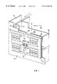
- FIG. 4 shows the front view of a partition 18 of self-commutated power converter 2 with only one three-point converter arm 12 per phase R, S, and T, according to the equivalent circuit diagram in accordance with FIG. 3 .
- This partition 18 which has three phase heat sinks 20 , 22 , and 24 , is used to partition a rearward ventilation space 26 from the front electronics space.
- Phase heat sinks 20 , 22 , and 24 are each detachably joined to partition 18 .
- Cooling fins 28 (not shown in this representation) of these phase heat sinks 20 , 22 , and 24 each protrude through an opening 30 of partition 18 into rearward ventilation space 26 (FIG. 7 ).
- the three phase heat sinks 20 , 22 , and 24 are arranged one over another.
- High-power power modules T 1 1 . . . T 1 4 , T 2 1 . . . T 2 4 , and T 3 1 . . . T 3 4 are joined phasewise to a phase heat sink 20 , 22 , and 24 , respectively, in a detachable manner.
- Detachably joined to these phase heat sinks 20 , 22 , and 24 are also midpoint diodes D 1 1 , D 1 2 , D 2 1 , D 2 2 , and D 3 1 , D 3 2 , these diodes being arranged in each case centrically between high-power modules T 1 1 . . . T 1 4 , T 2 1 . . . T 2 4 , and T 3 1 . . . T 3 4 .
- FIG. 5 shows the front view of partition 18 of self-commutated power converter 2 with two three-point converter arms 12 and 14 per phase R, S, and T, according to the equivalent circuit diagram in accordance with FIG. 3 .
- This specific embodiment differs from the specific embodiment according to FIG. 4 in that each phase heat sink 20 , 22 , and 24 has four further high-power modules T 1 5 . . . T 1 8 , T 2 5 . . . T 2 8 , and T 3 5 . . . T 3 8 .
- the placement of these individual high-power modules T 1 1 . . . T 1 8 , T 2 1 . . . T 2 8 , and T 3 1 . . . T 3 8 depends primarily on the design of the low-inductive busbar system having the two link busbars and a midpoint busbar. By the increase in the number of modules, only the width of phase heat sinks 20 , 22 , and 24 changes, respectively.
- FIG. 6 shows the front view of partition 18 of self commutated power converter 2 with three three-point converter arms 12 , 14 and 16 per phase R, S, and T, according to the equivalent circuit diagram in accordance with FIG. 3 .
- This specific embodiment differs from the specific embodiment according to FIG. 5 in that each phase heat sink 20 , 22 , and 24 has four further high-power modules T 1 9 . . . T 1 12 , T 2 9 . . . T 2 12 , and T 3 9 . . . T 3 12 , as well.
- T 1 9 . . . T 1 12 the specific phase heat sink 20 , 22 , and 24 has four further high-power modules T 1 9 . . . T 1 12 , T 2 9 . . . T 2 12 , and T 3 9 . . . T 3 12 , as well.
- FIG. 7 shows a cut-away portion of self-commutated power converter 2 according to FIG. 4 .
- the air-discharge duct 32 arranged in ventilation space 26 is visible.
- This air-discharge duct 32 has a cuboidal design, its large face 34 , which faces cooling fins 28 of phase heat sinks 20 , 22 , and 24 , having a centrical opening 36 . Longitudinal edges 38 of this centrical opening 36 are each folded up.
- Cooling fins 28 of phase heat sinks 20 , 22 , and 24 are each raised in the region of high-power modules T 1 1 . . . . T 1 4 , T 2 1 . . . T 2 4 , and T 3 1 . . .
- high-power modules T 3 1 . . . T 3 4 are arranged on fin base 40 of heat sink 24 in a manner that they are rotated by 90°.
- a phase heat sink 24 having a particularly compact design is obtained. If a plurality of three-point converter arms 12 , 14 , and 16 are used per phase R, S, and T, then high-power modules T 1 1 . . . T 1 12 , T 2 1 . . . T 2 12 , and T 3 1 . . . T 3 12 are arranged as in FIGS.
- each fin base 40 of phase heat sinks 20 , 22 , or 24 has a surrounding rim 42 via which phase heat sinks 20 , 22 , or 24 can support themselves against partition 18 .
- Openings 30 of partition 18 are arranged relative to each other in such a manner that, in addition, phase heat sinks 22 and 20 can support themselves against phase heat sinks 24 and 22 , respectively, with the assistance of their surrounding rims 42 .
- a sealing ring can be arranged between a surrounding rim 42 of a phase heat sink 20 , 22 or 24 , respectively, and partition 18 .
- each phase heat sink 20 , 22 , and 24 receives fresh cooling air on both sides, respectively, so that the same cooling conditions prevail for each high-power module T 1 1 . . . T 1 4 , T 2 1 . . . T 2 4 , and T 3 1 . . . T 3 4 .
- cooling-air guide ducts 44 and 46 are provided in ventilation space 26 , of which only cooling-air guide duct 44 is shown in FIG. 7 .
- These cooling-air guide ducts 44 and 46 are arranged on both sides of air-discharge duct 32 , and connect rearward air-inlet openings of ventilation space 26 to the end faces of cooling fins 28 of phase heat sinks 20 , 22 , and 24 , the end faces constituting air supplies.
- these cooling-air guide ducts 44 and 46 can be divided into three separate air-guide ducts by transverse barriers arranged one over another.
- cooling-air guide ducts 44 and 46 By these cooling-air guide ducts 44 and 46 , the flow velocity of the cooling air can be increased so that the flow rate is increased. If barriers are used in each cooling-air guide duct 44 and 46 , then the cooling circuits of phase heat sinks 20 , 22 , and 24 are decoupled from each other with respect to the fresh air.
- the exhaust air is sucked off upward in air-discharge duct 32 by at least one fan.
- This exhaust air can also be sucked off downward.
- a plurality of small fans being arranged at the back wall along the width of air-discharge duct 32 .
- the air-discharge duct must be connected to the fans by a connecting duct.
Abstract
Description
Claims (11)
Applications Claiming Priority (3)
| Application Number | Priority Date | Filing Date | Title |
|---|---|---|---|
| DE19756250 | 1997-12-17 | ||
| DE19756250A DE19756250C2 (en) | 1997-12-17 | 1997-12-17 | Self-commutated converter of a voltage-impressing converter with high-performance modules |
| PCT/DE1998/003570 WO1999031791A1 (en) | 1997-12-17 | 1998-12-04 | Self-commutated power converter of a voltage-impressing converter with n high-power modules |
Publications (1)
| Publication Number | Publication Date |
|---|---|
| US6219266B1 true US6219266B1 (en) | 2001-04-17 |
Family
ID=7852339
Family Applications (1)
| Application Number | Title | Priority Date | Filing Date |
|---|---|---|---|
| US09/581,725 Expired - Fee Related US6219266B1 (en) | 1997-12-17 | 1998-12-04 | Self-commutated power converter of a voltage-impressing converter with N high-power modules |
Country Status (4)
| Country | Link |
|---|---|
| US (1) | US6219266B1 (en) |
| EP (1) | EP1040560B1 (en) |
| DE (2) | DE19756250C2 (en) |
| WO (1) | WO1999031791A1 (en) |
Cited By (8)
| Publication number | Priority date | Publication date | Assignee | Title |
|---|---|---|---|---|
| US6690585B2 (en) | 2001-08-29 | 2004-02-10 | Oqo, Inc. | Bi-directional DC power conversion system |
| CN102005989A (en) * | 2010-10-14 | 2011-04-06 | 中国北车股份有限公司大连电力牵引研发中心 | Suspension controller of magnetic suspension train |
| CN102189310A (en) * | 2010-03-10 | 2011-09-21 | 株式会社大亨 | Power supply apparatus |
| CN101699733B (en) * | 2009-11-05 | 2012-01-25 | 中国北车股份有限公司大连电力牵引研发中心 | Ventilating device for current transformer |
| US20120188807A1 (en) * | 2011-01-25 | 2012-07-26 | Fuji Electric Co., Ltd. | Stacked structure of power conversion apparatus |
| EP3145286A1 (en) * | 2015-09-15 | 2017-03-22 | ABB Schweiz AG | Heat dissipation in power electronic assemblies |
| US9954459B2 (en) * | 2015-02-24 | 2018-04-24 | Meidensha Corporation | Inverter device |
| US11690195B2 (en) * | 2020-09-11 | 2023-06-27 | Abb Schweiz Ag | Power semiconductor cooling system |
Families Citing this family (7)
| Publication number | Priority date | Publication date | Assignee | Title |
|---|---|---|---|---|
| DE10101277B4 (en) * | 2001-01-12 | 2006-11-02 | Wacker Construction Equipment Ag | High-frequency internal vibrator with cooled electronic frequency converter |
| DE10323982A1 (en) * | 2003-05-27 | 2004-12-30 | Institut für Luft- und Kältetechnik gGmbH | Inverter e.g. for solar modules, is releasably mounted on rear-surface of solar module and housing and ground-plate have spacer-retainer forming air-gap |
| DE10339216A1 (en) * | 2003-08-05 | 2004-10-28 | Siemens Ag | Three-point power converter, has heat sink and multiple different semiconductor devices, arranged so that dissipated energy decreases in propagation direction of cooling medium |
| EP2299582B1 (en) * | 2009-09-18 | 2015-03-11 | SMA Solar Technology AG | Inverter with a housing and electric and electronic components assembled within same |
| WO2012062711A2 (en) | 2010-11-10 | 2012-05-18 | Abb Technology Ag | Assembly for cooling power semiconductors |
| CN103129409B (en) * | 2013-03-04 | 2015-10-21 | 南车株洲电力机车有限公司 | A kind of control setup of aerotrain |
| DE102020214795A1 (en) * | 2020-11-25 | 2022-05-25 | Robert Bosch Gesellschaft mit beschränkter Haftung | Power module with an isolated split heat sink and vehicle with the power module |
Citations (8)
| Publication number | Priority date | Publication date | Assignee | Title |
|---|---|---|---|---|
| US4296455A (en) * | 1979-11-23 | 1981-10-20 | International Business Machines Corporation | Slotted heat sinks for high powered air cooled modules |
| US4315300A (en) * | 1979-01-29 | 1982-02-09 | The United States Of America As Represented By The Secretary Of The Navy | Cooling arrangement for plug-in module assembly |
| US4682268A (en) | 1985-02-07 | 1987-07-21 | Nec Corporation | Mounting structure for electronic circuit modules |
| EP0356991A2 (en) | 1988-08-31 | 1990-03-07 | Hitachi, Ltd. | Inverter device |
| US5218516A (en) * | 1991-10-31 | 1993-06-08 | Northern Telecom Limited | Electronic module |
| DE4316999A1 (en) | 1993-05-21 | 1994-11-24 | Rieter Ingolstadt Spinnerei | Device for heat dissipation from an interior of a control cabinet of a textile machine |
| EP0658934A2 (en) | 1993-12-15 | 1995-06-21 | Siemens Aktiengesellschaft | Heat sink |
| US5477416A (en) | 1995-02-14 | 1995-12-19 | Hewlett-Packard Company | Enclosure with metered air ducts for mounting and cooling modules |
-
1997
- 1997-12-17 DE DE19756250A patent/DE19756250C2/en not_active Expired - Fee Related
-
1998
- 1998-12-04 US US09/581,725 patent/US6219266B1/en not_active Expired - Fee Related
- 1998-12-04 WO PCT/DE1998/003570 patent/WO1999031791A1/en active IP Right Grant
- 1998-12-04 EP EP98966192A patent/EP1040560B1/en not_active Expired - Lifetime
- 1998-12-04 DE DE59804933T patent/DE59804933D1/en not_active Expired - Lifetime
Patent Citations (8)
| Publication number | Priority date | Publication date | Assignee | Title |
|---|---|---|---|---|
| US4315300A (en) * | 1979-01-29 | 1982-02-09 | The United States Of America As Represented By The Secretary Of The Navy | Cooling arrangement for plug-in module assembly |
| US4296455A (en) * | 1979-11-23 | 1981-10-20 | International Business Machines Corporation | Slotted heat sinks for high powered air cooled modules |
| US4682268A (en) | 1985-02-07 | 1987-07-21 | Nec Corporation | Mounting structure for electronic circuit modules |
| EP0356991A2 (en) | 1988-08-31 | 1990-03-07 | Hitachi, Ltd. | Inverter device |
| US5218516A (en) * | 1991-10-31 | 1993-06-08 | Northern Telecom Limited | Electronic module |
| DE4316999A1 (en) | 1993-05-21 | 1994-11-24 | Rieter Ingolstadt Spinnerei | Device for heat dissipation from an interior of a control cabinet of a textile machine |
| EP0658934A2 (en) | 1993-12-15 | 1995-06-21 | Siemens Aktiengesellschaft | Heat sink |
| US5477416A (en) | 1995-02-14 | 1995-12-19 | Hewlett-Packard Company | Enclosure with metered air ducts for mounting and cooling modules |
Non-Patent Citations (1)
| Title |
|---|
| C. Tietze et al., "Transistorwechselrichter für Nahverkehrstriebfahrzeuge", Elektrische Bahnen, 1993, No. 11, pp. 341-347*** . |
Cited By (11)
| Publication number | Priority date | Publication date | Assignee | Title |
|---|---|---|---|---|
| US6690585B2 (en) | 2001-08-29 | 2004-02-10 | Oqo, Inc. | Bi-directional DC power conversion system |
| CN101699733B (en) * | 2009-11-05 | 2012-01-25 | 中国北车股份有限公司大连电力牵引研发中心 | Ventilating device for current transformer |
| CN102189310A (en) * | 2010-03-10 | 2011-09-21 | 株式会社大亨 | Power supply apparatus |
| CN102005989A (en) * | 2010-10-14 | 2011-04-06 | 中国北车股份有限公司大连电力牵引研发中心 | Suspension controller of magnetic suspension train |
| CN102005989B (en) * | 2010-10-14 | 2012-09-05 | 中国北车股份有限公司大连电力牵引研发中心 | Suspension controller of magnetic suspension train |
| US20120188807A1 (en) * | 2011-01-25 | 2012-07-26 | Fuji Electric Co., Ltd. | Stacked structure of power conversion apparatus |
| US8724358B2 (en) * | 2011-01-25 | 2014-05-13 | Fuji Electric Co., Ltd. | Stacked structure of power conversion apparatus |
| US9954459B2 (en) * | 2015-02-24 | 2018-04-24 | Meidensha Corporation | Inverter device |
| EP3145286A1 (en) * | 2015-09-15 | 2017-03-22 | ABB Schweiz AG | Heat dissipation in power electronic assemblies |
| US10306814B2 (en) | 2015-09-15 | 2019-05-28 | Abb Schweiz Ag | Heat dissipation in power electronic assemblies |
| US11690195B2 (en) * | 2020-09-11 | 2023-06-27 | Abb Schweiz Ag | Power semiconductor cooling system |
Also Published As
| Publication number | Publication date |
|---|---|
| EP1040560A1 (en) | 2000-10-04 |
| DE19756250C2 (en) | 2000-11-02 |
| WO1999031791A1 (en) | 1999-06-24 |
| EP1040560B1 (en) | 2002-07-24 |
| DE19756250A1 (en) | 1999-07-01 |
| DE59804933D1 (en) | 2002-08-29 |
Similar Documents
| Publication | Publication Date | Title |
|---|---|---|
| US6219266B1 (en) | Self-commutated power converter of a voltage-impressing converter with N high-power modules | |
| JP3314256B2 (en) | Electric vehicle power converter | |
| JP3563038B2 (en) | Power converter | |
| EP0794098B1 (en) | Electric power transforming apparatus for electric rolling stock | |
| JP6296888B2 (en) | Power converter | |
| US8169780B2 (en) | Power conversion device | |
| US8148859B2 (en) | Cooling structure for inverter and capacitor accommodated integrally with motor in housing of motor, motor unit with cooling structure, and housing | |
| JP4243308B2 (en) | Power converter | |
| US20120147633A1 (en) | AC-to-AC converter and method for converting a first frequency AC-voltage to a second frequency AC-voltage | |
| US20110199736A1 (en) | Power converter | |
| AU2015200406B2 (en) | Integrated mounting and cooling apparatus, electronic device, and vehicle | |
| JP2004087711A (en) | Forced air-cooled power conversion apparatus | |
| US10504820B2 (en) | Semiconductor module and electric power conversion device | |
| JP3367411B2 (en) | Power converter | |
| EP3661042A1 (en) | Electric-power conversion device | |
| JP6804543B2 (en) | Power converter, cooling structure, power conversion system and power supply | |
| JP2006149199A (en) | Power conversion apparatus for rail vehicle | |
| JP3822612B2 (en) | Railway vehicle power converter | |
| WO2019146179A1 (en) | Power conversion device and electric railroad vehicle equipped with power conversion device | |
| US20220181981A1 (en) | Power converter | |
| KR20130021570A (en) | Wator cooling type invertor | |
| JP6761908B2 (en) | Power converter | |
| JP3799352B2 (en) | Power converter | |
| EP3474426A1 (en) | Inverter for an electric machine comprising a cooling channel, electric machine for a vehicle and vehicle | |
| US20240072708A1 (en) | Inverter structure of an inverter of a power electronics module for operating an electric drive of a motor vehicle |
Legal Events
| Date | Code | Title | Description |
|---|---|---|---|
| AS | Assignment |
Owner name: SIEMENS AKTIENGESELLSCHAFT, GERMANY Free format text: ASSIGNMENT OF ASSIGNORS INTEREST;ASSIGNOR:PFAUSER, ANTON;REEL/FRAME:010912/0855 Effective date: 20000511 |
|
| FEPP | Fee payment procedure |
Free format text: PAYOR NUMBER ASSIGNED (ORIGINAL EVENT CODE: ASPN); ENTITY STATUS OF PATENT OWNER: LARGE ENTITY |
|
| FPAY | Fee payment |
Year of fee payment: 4 |
|
| AS | Assignment |
Owner name: UBS AG, STAMFORD BRANCH, CONNECTICUT Free format text: SECOND LIEN SECURITY AGREEMENT;ASSIGNOR:TARGUS GROUP INTERNATIONAL, INC.;REEL/FRAME:017215/0171 Effective date: 20051122 Owner name: GOLDMAN SACH CREDIT PARTNERS L.P., NEW YORK Free format text: FIRST LIEN SECURITY AGREEMENT;ASSIGNOR:TARGUS GROUP INTERNATIONAL, INC.;REEL/FRAME:017215/0164 Effective date: 20051122 |
|
| REMI | Maintenance fee reminder mailed | ||
| LAPS | Lapse for failure to pay maintenance fees | ||
| STCH | Information on status: patent discontinuation |
Free format text: PATENT EXPIRED DUE TO NONPAYMENT OF MAINTENANCE FEES UNDER 37 CFR 1.362 |
|
| FP | Lapsed due to failure to pay maintenance fee |
Effective date: 20090417 |
|
| AS | Assignment |
Owner name: TARGUS GROUP INTERNATIONAL, INC., CALIFORNIA Free format text: CORRECTIVE ASSIGNMENT TO CORRECT THE FIRST LIEN SECURITY AGREEMENT PREVIOUSLY RECORDED ON REEL 017215 FRAME 0164;ASSIGNOR:GOLDMAN SACHS CREDIT PARTNERS L.P.;REEL/FRAME:023861/0037 Effective date: 20051122 Owner name: TARGUS GROUP INTERNATIONAL, INC., CALIFORNIA Free format text: CORRECTIVE ASSIGNMENT TO CORRECT THE SECOND LIEN SECURITY AGREEMENT PREVIOUSLY RECORDED ON REEL 017215 FRAME 0171;ASSIGNOR:UBS AG, STAMFORD BRANCH;REEL/FRAME:023861/0025 Effective date: 20051122 Owner name: TARGUS GROUP INTERNATIONAL, INC., CALIFORNIA Free format text: CORRECTIVE ASSIGNMENT TO CORRECT THE FIRST LIEN SECURITY AGREEMENT PREVIOUSLY RECORDED ON REEL 017215 FRAME 0164;ASSIGNOR:TARGUS GROUP INTERNATIONAL, INC.;REEL/FRAME:023861/0013 Effective date: 20051122 |