US6234765B1 - Ultrasonic phase pump - Google Patents
Ultrasonic phase pump Download PDFInfo
- Publication number
- US6234765B1 US6234765B1 US09/258,387 US25838799A US6234765B1 US 6234765 B1 US6234765 B1 US 6234765B1 US 25838799 A US25838799 A US 25838799A US 6234765 B1 US6234765 B1 US 6234765B1
- Authority
- US
- United States
- Prior art keywords
- transducer
- interior
- cylindrical
- bubble
- fluid
- Prior art date
- Legal status (The legal status is an assumption and is not a legal conclusion. Google has not performed a legal analysis and makes no representation as to the accuracy of the status listed.)
- Expired - Fee Related
Links
Images


Classifications
-
- F—MECHANICAL ENGINEERING; LIGHTING; HEATING; WEAPONS; BLASTING
- F04—POSITIVE - DISPLACEMENT MACHINES FOR LIQUIDS; PUMPS FOR LIQUIDS OR ELASTIC FLUIDS
- F04F—PUMPING OF FLUID BY DIRECT CONTACT OF ANOTHER FLUID OR BY USING INERTIA OF FLUID TO BE PUMPED; SIPHONS
- F04F7/00—Pumps displacing fluids by using inertia thereof, e.g. by generating vibrations therein
Definitions
- This particular invention relates to fluid pumps and to ultrasonic pumps for fluid comprising a liquid, a liquid metal, a gas, or an aerosol medium and irrespective of the character or nature of the installation or system in which the pump is employed.
- the two categories of electro-mechanical pumps namely; force and compression pumps all require moving parts for proper operation and in some special way these parts are designed in relation to the amount of fluid to be pumped per unit time and further the overall volume of the physical pump design.
- Compression pumps known as positive displacement types are capable of generating great pressure, nevertheless requires many moving parts such as a piston, piston rod, crankshaft, and associated valve assemblies.
- Positive displacement constriction pumps are the safest; mainly because the pumped fluid never contacts an n environment different than its internal tubing. They are for this fact used widely in the medical and pharmaceutical sector where the prevention of contamination is a vital factor.
- Their major disadvantage lies in the possible crushing forces upon the material being pumped if the tubing constricts completely.
- the moving parts required therein wear out from the fatigue caused by continuous operation.
- the frequency of oscillation of the diaphragm piezoelectric transducer and the length of the pump chamber are configured together so that this arrangement forms a resonant cavity (chamber) where acoustic standing waves are established in the fluids which allows for a pressure node or antinode at the wall opposite the diaphragm piezoelectric transducer.
- a series of pressure nodes and antinodes are distributed along the length of the chamber, and the number of nodes and antinodes depending upon the length of the chamber and the frequency of vibration of the diaphragm piezoelectric transducer.
- Mandroian further describes that the entrance port for the fluid is located in the chamber at one of the pressure nodes and an exit port is located at one of the pressure antinodes.
- This embodiment requires that a resonant condition must be created before any pumping action occurs and further, it is critical to have the dimensions of the chamber such that the entrance and exit ports are precisely on the nodes and antinodes for proper operation. This proper operation relies heavily on frequency resonant conditions within the chamber; if for any reason there is a frequency shift, then the efficiency of operation is decreased.
- the compressors used in both Lucas' patents likewise utilize embodiments which uses standing waves of acoustic pressure for creating nodes which are periodic points of minimum pressure and antinodes which are periodic points of maximum pressure.
- the standing wave phenomenon of course requires a resonant state for proper operation so as with these compressors of the Lucas patents.
- compressors require that a very narrow resonant operational frequency range be utilized by way of specific electronic control circuitry.
- This control circuitry includes microprocessor controlled phase locked loops to insure frequency stability, thus adding to the complexity of the design.
- Such control circuitry is necessary for such a complex compressor system used for refrigeration.
- Lucas' compressors require the creation of a standing wave within a resonant chamber or cavity, and further attempting to maintain the standing wave with its fixed periodic nodes and antinodes of pressure. These nodes and antinodes are required to be precisely located at the entrance and exit fluid ports. This is done for the purpose of moving a gaseous refrigerant one way into a heat exchanger, where the excess heat generated from compression is carried off and the gaseous refrigerant is thereby cooled to a liquid phase. This cooled liquid is then passed through a volume that contains a number of ingredients to be cooled—such as food, etc.
- the liquid heats up and expands into the gaseous phase once more; only then to re-enter the resonant chamber of the compressor to begin the cycle all over again.
- the internal mechanism of the compressor requires a longitudinal standing wave and that such a wave must be transverse to the exit and entrance ports. This mechanism is further established by action of streaming effecting the overall efficiency of such compressors by taking away energy from the wave. This streaming effect occurs when the very same pressure differentials that allow for transverse gaseous flow between exit and entrance ports, are of sufficient amplitude to cause a gaseous flow between the nodes and antinodes within the resonant chamber.
- Another feature of the compressors of Lucas' patents is the use of one or more ultrasonic drivers, which emit periodic ultrasonic energy, which may or may not be linear in nature. It is stated that the frequency of the transducer is above the standing wave frequency. It is then asserted that the energy is demodulated into pulses of complex waves, and that this is accomplished by the higher frequency components being attenuated by the gaseous environment. What is left then, is a pulsed complex wave with lower frequency components; some of which fall into the frequency range of the standing wave frequency and add energy thereto.
- an ultrasonic transducer can be used in a non resonant pulsed or modulated mode, “non resonant mode” meaning that the frequency of the transducer is not equal to the frequency of the standing acoustical wave.
- non resonant mode meaning that the frequency of the transducer is not equal to the frequency of the standing acoustical wave.
- the transducer operates at its resonant mode and “that” mode is much higher than the standing wave frequency by design.
- the transducer is switched on and off to create a succession of short pulses; each pulse consists of a short train of high frequency oscillations.
- Acoustic standing waves are the primary mode of operation of the prior art. Furthermore the standing waves are increased to their maximum value (taking into consideration system losses) after the generation of a traveling wave from a transducer or other source of acoustic energy. Further, this maximum value assigned to the standing wave is sustained by the constant acoustic energy injected into the system trough the transducer element.
- a gaseous fluid is the medium of choice for the compressors of Lucas' in order to function properly as a refrigeration compressor.
- the actual gaseous fluid flow is transverse to the acoustic standing wavefront.
- Precise geometry of the chamber is essential for successful operation requiring a resonant mode for the chamber; and additional electronic control measures are required to provide frequency compensation circuitry; such as phase locked loops that adjusts for frequency drift above and below the resonant mode of the chamber.
- Lucas compressors can utilize a multiplicity of acoustic energy sources situated at any one or all of the acoustic generated pressure nodes and antinodes, for the purpose of feeding additional energy at these points to increase the overall system efficiency.
- the prior Deak pump provides an optional ultrasonic transducer arrangement using either a single frequency range or a broadband frequency range using a special design configured transducer, which provide pumping action not requiring a resonant pump chamber, thereby eliminating numerous special arrangements inherent with such resonant pump designs.
- an ultrasonic pump which comprises two or more hollow cylindrical tube type ultrasonic transducers with a fluid input valve and an output valve or storage chamber.
- the pump receives fluids from the input port and once it is entered it is moved along with the traveling standing wave of acoustic pressure that is established within the space volume of the two hollow cylindrical transducers. Once the fluid reaches the other end it exits through the output port, or it can be stored or compressed for a multiplicity of applications including compressing gases or atomizing vapors.
- FIG. 1 is a mathematical plot of a Brillouin primary zone of phonon activity; (i.e.) motion of the phonon's dispersion relation for linear monatomic chains;
- FIG. 2 is a graphical phonon illustration of transverse acoustical standing waves
- FIG. 3 is a graphical phonon illustration of long wavelength acoustic waves
- FIG. 4 is a partial cross-sectional view of a basic two element hollow cylinder ultrasonic phase pump configuration according to one embodiment of the present invention
- FIG. 5 is a partial cross-sectional view of a basic two element hollow cylinder ultrasonic phase pump configuration with a multiplicity of segmented transducer elements according to an alternate embodiment of the present invention
- FIG. 6 is a partial cross-sectional view of a basic two element hollow cylinder ultrasonic phase pump configuration, showing the movement of standing acoustical waves set up between the two different transducer elements according to an alternate embodiment of the present invention
- FIG. 7 is a partial cross-sectional view of a basic two element hollow cylinder ultrasonic phase pump configuration, showing the movement of standing acoustical waves set up between the two different transducer elements and including a storage area for pressure build up and with an output port according to an alternate embodiment of the present invention
- FIG. 8 is a partial cross-sectional view of a segmented hollow cylinder ultrasonic phase pump configuration, showing the movement of standing acoustical waves set up between the two different transducer elements, and a storage area for pressure build up and with an output port according to an alternate embodiment of the present invention
- FIG. 9 is a partial cross-sectional view of a segmented hollow cylinder ultrasonic phase pump configuration, showing the movement of standing acoustical waves set up between the two different transducer elements, and a storage area for pressure build up and without an output port, but including a transparent quartz window, is for the generation of and transmission of sustained sonoluminescence, according to an alternate embodiment of the present invention
- FIG. 10 is a block drawing of a prior art experimental set up procedure used by anyone steeped in the art to produce sonoluminescence for observation and data collection;
- FIGS. 11A & 11B are perspective images of a shock wave emitted by a sonoluminescencing bubble a time t after collapse, and the reflection off the side walls of the cavity before collapse, respectively;
- FIG. 12 is mathematical plot of average velocities of the shock wave
- FIG. 13 is a mathematical plot of numerical calculations of a shock wave generated at collapse time of a bubble of 5 microns radius with an inset showing peak pressure that is traveling away from the bubble into the liquid;
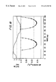
- FIG. 15 is a mathematical plot of the bubble response for 2-mode driving as a function of the phase difference (in degrees) between the driving sinusoidal signal and its second harmonic, wherein the upper trance is the vertical position of the bubble and the thick dotted lines denote unstable bubble behavior, while the lower trace shows the corresponding photo current, with open circles showing the maximum SL intensity achieved, and the dashed line is the maximal photo current for pure sine-wave driving;
- FIG. 16 are mathematical plots of time series of the driving (top) and the radius of calculated bubble collapses (bottom) for single (dashed) and optimized multi-mode driving signals (2-mode: line, 8-mode: dotted);
- FIG. 17 is a magnified portion of the mathematical plot of the first collapses of FIG. 15, with the time axis is shifted so that the collapses take place at 0, 0.5, and 1 ns, respectively, showing the curves for 1-mode (dashed), optimized 2-mode (line) and optimized 8-mode (dotted) driving, wherein the time series of the bubble collapses exhibit a decrease in minimum radius (left) and increase in the adiabatically calculated temperature (right) as a function of the number of modes in the driving sound, and including an indication of the van der Waals hard core, shown by the horizontal line in the left graph; and
- FIG. 18 is a mathematical plot of the calculated vertical bubble position (upper) and resulting minimum radius (lower) as a function of the phase difference for double harmonic driving of a bubble, wherein the dashed line in the lower plot is the minimum radius for single frequency driving with the same power, and the solid straight line is a reference to the van der Waals hard core.
- Un ⁇ 1 The displacement of atom n ⁇ 1 from its equilibrium position.
- Un+1 The displacement of atom n+1 from its equilibrium position.
- Equation 2 is not a wave equation, but assume a traveling wave or a traveling standing wave solution as:
- FIG. 1 shows the dispersion curve which is the periodicity of the function.
- the repeat period is 2 ⁇ / ⁇ , which is equal to the unit cell length in the reciprocal lattice.
- Ergo the useful information is contained in the waves with wave vectors lying between the limits: - ⁇ a ⁇ k ⁇ ⁇ a Equation ⁇ ⁇ 5
- This range of wave vectors is called the first Brillouin zone.
- the nearest atoms of the chain vibrate in the opposite direction and the wave becomes a standing wave.
- k approaches zero (the long-wavelength limit)
- ⁇ 0 is the phase velocity, which is equivalent to the velocity of a sound in the crystal.
- Phonons with a frequency which goes to zero in the limit of small k are known as acoustical phonons.
- the broadest example of this present invention shows an outer ultrasonic cylindrical type transducer 1 which has it phonon emission source emanating from the inside surface of it's hollow cylindrical structure.
- an inner ultrasonic cylindrical transducer 2 Directly in parallel with and inserted within the outer ultrasonic cylindrical type transducer 1 , is an inner ultrasonic cylindrical transducer 2 , which has it's source of phonon emission on the outer surface of said transducer.
- the physical length of these transducers are such that they can be an integral number of wavelengths long so as to set up conditions for a whole number of standing waves based upon a certain frequency. These standing waves are established in the hollow section 3 between the outer ultrasonic cylindrical type transducer 1 and the inner ultrasonic cylindrical transducer 2 .
- These outer and inner ultrasonic transducers are of a continuous type with a uniform piezoelectric surface through their intended emission source, but not limited to a continuous uniform surface area.
- Alternate embodiments comprise a series of isolated section of piezoelectric surface areas independent of each other and both electrically and mechanically isolated from each other to form an array of piezoelectric surface areas. This is illustrated in FIG. 5 .
- Each section is selectively excited by a signal having relative phase displacement as provided by a signal generator and a phase shifter for each corresponding transducer section.
- These sections 2 A, 2 B, 2 C, 2 D . . . (etc.) are electrically and mechanically isolated while including a fluid seal therebetween to maintain integrity of the overall fluid chamber retaining fluid between the inner and outer transducers.
- non-piezoelectric separators for the outer transducer 1
- the non-piezoelectric separators are shown as item 12 .
- the simple form of the phase pump is shown in FIG. 4 where only one continuous section of outer 1 and inner 2 transducers are employed for operation. Electrical pulses are sent to excite the outer 1 and the inner 2 transducers so as to cause emission of phonons into the hollow region of said phase pump. There upon, a wavefront is set up in the fluid medium contained within the hollow region 3 of said phase pump.
- FIG. 6 shows movement of the standing waves 10 - a from left to right in the simplest form of the invention using only a single outer transducer 11 and a single inner transducer 12 .
- FIG. 7 shows in the broadest sense, the established standing waves that are created between inner transducer 2 and outer transducer 1 and by producing a varying phase relationship to the electrical signal applied to said transducers.
- the traveling standing waves shift with applied momentum, and are stored through the porous region 9 which acts as a passive conveyance mechanism for the fluid to flow into the storage chamber 7 .
- the fluid waves 11 are built up to such pressure that they eventually trigger the one-way threshold valve 8 to open and thus allow for fluid flow to occur. This action creates a partial vacuum in area 4 , and a self-priming feature is seen as part of the total action of the pump.
- FIG. 8 the same action is described in a model that incorporates a multiplicity of inner 2 and outer 1 transducers.
- the inner 2 and outer 1 transducers are electrically and piezo-electrically isolated from one another by isolation segments 12 for the inner transducers 2 and by the isolation segments 11 for the outer transducers 1 .
- established standing waves that are created between inner transducer 2 and outer transducer 1 and by producing a varying phase relationship to the electrical signal applied to said transducers.
- the traveling standing waves shift with applied momentum, and are stored through the porous region 9 which acts as a passive conveyance mechanism for the fluid to flow into the storage chamber 7 .
- Cavitation is the process of forming micro-bubbles in a liquid by generating intense ultrasound waves.
- a cavity gas or vapor bubble
- SL sonoluminescence
- the history of sonoluminescence (“SL”) covers more than five decades, and from previous research (2), sonoluminescence is well-established as a branch of physics.
- Sonoluminescence is a non-equilibrium phenomenon in which energy in a sound wave becomes highly concentrated so as to generate flashes of light in a liquid.
- the SL light is also emitted just prior to the minimum (about 5-10 ns prior to Rc); Rm is about 40 ⁇ m and Rc is about 4 ⁇ m.
- ⁇ 2 ⁇ R 2 - 3 2 ⁇ R ⁇ ( ⁇ ⁇ R ) 2 + 1 ⁇ ⁇ ⁇ R ⁇ [ ( P 0 + 2 ⁇ ⁇ R 0 ) ⁇ ( R 0 R ) 3 ⁇ x - 2 ⁇ ⁇ R - 4 ⁇ ⁇ ⁇ ⁇ ⁇ R R - P 0 - P 0 ⁇ ( t ) ] .
- Equation ⁇ ⁇ 8 Z ⁇ ( R max R min ) 3 ⁇ [ ( ⁇ - 1 ) ⁇ P + P a P o o + 2 ⁇ ⁇ R o ⁇ ( R max R o ) 3 ] 1 ⁇ - 1 Equation ⁇ ⁇ 9
- FIG. 9 the same action is described in a model that incorporates a multiplicity of inner 2 and outer 1 transducers.
- the inner 2 and outer 1 transducers are electrically and piezo-electrically isolated from one another by isolation segments 12 for the inner transducers 2 and by the isolation segments 11 for the outer transducers 1 .
- established standing waves that are created between inner transducer 2 and outer transducer 1 and by producing a varying phase relationship to the electrical signal applied to said transducers.
- the traveling standing waves shift with applied momentum, and are stored through the porous region 9 which acts as a passive conveyance mechanism for the fluid to flow into the storage chamber 7 .
- the fluid waves 21 are built up and stored, without fluid release, to such pressure that SONOLUMENSECENCE occurs within the cavity bubble 13 .
- the blue (SONOLUMENSECENT) light generated from the action of SONOLUMENSECENCE within the storage chamber 7 is emitted through the transparent quarts window 14 .
- the standing ultrasound wave is produced in a cylindrical cell filled with water of ambient temperature, distilled and de-gassed to 10-40% of ambient gas pressure.
- the cell comprises of two piezo-ceramic cylinders connected by a glass tube of 2.9 cm radius (overall height, 12 cm). An optical glass plate closes the bottom, and the top remains open.
- the driving frequency is 23.5 kHz and the driving amplitude is approximately equal to 1.2 to 1.5 bars of pressure.
- a bubble is inserted into the liquid with a syringe.
- the oscillating bubble is illuminated from the top by a copper vapor laser 34 by light pulses of 7 ns duration (FWHM) followed by a low intensity tail of 30 ns.
- the wavelength is 511 nm.
- the repetition rate of one-half the driving frequency provided by exciting system 36 is adjusted via a controllable delay to accommodate locking to the driving signal at a preset phase.
- shock waves modulate the phase of the laser light
- optical filtering is used to transform this information into intensity modulations. Therefore the bubble image is passed through a (magnifying) 4f spatial Fourier filter. Specifically, a dark-ground method is used that removes the zeroth order in the Fourier plane with a thin metal stick. Subsequently the image is picked up by a video camera 40 delivering 25 frames/s. The shutter opening time is 0.25 ms such that the average image of 2-3 shock waves is seen. Because of the stable repetitive bubble collapse a slow motion video of the oscillations and the shedding of shock waves is produced by slightly detuning the laser flash frequency. The images of the shock waves are digitized in a computer and their radius/time curves can be plotted.
- FIG. 11 shows the images of shock waves at different times.
- the shock is emitted at the main collapse of the bubble.
- the shock front shows up as a circle FIG. 11 a and no anisotropy is seen within the optical resolution limit of 1.5 microns, which indicates that the collapse is symmetric within that resolution limit.
- the front proceeds to the outer glass wall of the cylinder, reflects, and moves inward again.
- the reflected shock wave has a duration >40 ns and is distorted, presumably due to imperfections or misalignment of the glass wall.
- 11 b shows the shock wave at the time it is refocused the most (3.54 microseconds before the next collapse).
- the main pressure peak seems to be approximately 700 microns away from the bubble at the lower end of a line structure.
- the refocused shock is sometimes powerful enough to kick the bubble through space a bit as it passes it. Weaker secondary reflections are also observable.
- the duration of the shock pulse can be determined to be 10 ns (FWHM). As this is on the order of the optical pulse length of 7 ns, this value is an upper bound.
- FIG. 12 shows the average velocities as a function of distance from the bubble center. At very small distances (6-73 microns) an average value of the velocity is 2000 m/s is measured, at larger distances the velocity of the shock front is decreasing to the ambient sound speed. Because the velocity of the shock decreases rapidly, the instantaneous velocity may be well above 2000 m/s.
- the pressure p in the shock can be determined from its velocity ⁇ by a Rankine-Hugeniot relation and a state equation for water, namely, the Tait equation.
- the shock pressure can be calculated to be 500 bars. Numerical calculations have been carried out to further analyze the time dependence of the velocity and pressure of the shock front.
- R is the bubble radius
- C, ⁇ , and p are the speed of sound in the liquid, its density, and the pressure at the bubble wall, respectively.
- H ⁇ p ⁇ ( R ) ⁇ ⁇ - 1 ⁇ ⁇ p Equation ⁇ ⁇ 12B
- p c and f are the driving pressure and frequency.
- Crossing characteristics in r-t space imply the generation of a shock.
- the exact position of the shock front can be obtained by equalization of the particle velocities in the hysteretic u-t curves.
- FIG. 13 shows the calculated shock wave velocity as a function of the distance from the bubble center.
- the maximal velocity of the pressure peak of approximately 8300 m/s decreases within the first hundred microns to the ambient sound velocity.
- the mean velocity of the peak is shown in FIG. 13 .
- the experimentally obtained short time average and mean velocities compare quite well to the numerical findings.
- the particle velocity in the model reaches a maximum value of 333 m/s.
- the inset in FIG. 13 shows the peak pressure of the shock as it travels away from the center.
- the maximum value of 73000 bars at 1 micron decays quickly with increasing distance, within 100 microns with a faster decay rate than the usual. Though these numbers may be somewhat overestimated due to model limitations, it is seen that within the first few m extreme conditions exist in the fluid. The greater dissipation close to the bubble may account for differences between our experimental results and previous inferences of the shock pressure from direct hydrophone measurements, which have yielded smaller values for the pressure.
- the shock wave as a microscope for the bubble position at collapse time, the time dependence and the position of the collapse have been measured for unstable SBSL.
- Unstable SBSL occurs at the upper parameter values of the driving pressure and ambient gas concentration: The ambient bubble radius grows until the bubble dynamics reaches an instability where bubble volume is rapidly lost. This cycle repeats itself on a slow time scale. Using rare events of double exposure at split-off time, the distance of the centers of two shock waves representing a bubble before and after the split-off can be used to calculate a lower bound of the bubble velocity due to the recoil of 0.5 m/s.
- FIG. 13 shows numerical calculations of a shock wave generated at collapse time of a bubble of 5 microns ambient radius driven at 23.5 kHz and 1.45 bars. Shown are data for the pressure peak that is traveling away from the bubble into the liquid as a function of distance from the bubble center. Dashed line: velocity of the peak; solid line: extrapolated mean shock velocity; squares: particle velocity. The inset shows the calculated peak pressure in the shock as a function of distance from the bubble (solid line). The dotted line shows a 1/ ⁇ reference line for comparison.
- FIG. 14 shows the radius of the shock wave and the bubble position at collapse time as a function of time. All experimental conditions were kept constant. It is seen that the bubble collapse does not occur at a constant phase any more. As the ambient bubble radius grows by diffusion, the collapse is shifted to later times. Because the illuminating flash occurs at a fixed phase of the driving signal some small time after the collapse, a later collapse decreases the time the shock front can travel outward until it is imaged. This way a larger ambient bubble radius shows up as a smaller shock radius. In FIG. 14 a the recurrent process of growing on a slow time scale and a subsequent rapid decrease of ambient volume of the bubble is seen.
- FIG. 14 shows measured radii of shock waves and position of the center during unstable SBSL. Data have been digitized from images taken each 40 ms at a constant phase of the driving.
- the upper line shows the radii of shock waves as a function of time, as they change on a slow time scale. The lower two lines are relative x and y coordinates of the bubble at collapse.
- (b) Zoom into the first seconds of (a). Spatial oscillations are seen as the shock radii (and the ambient radius of the bubble) are changing at, e.g., t 8-9 s.
- the experimental setup is as follows: An air bubble is trapped in a water filled cell consisting of two piezoceramic cylinders connected via a glass tube.
- the levitation cell (“Crum cell”) is standing upright with a glass plate covering the lower end of the cell. The upper end remains open.
- a video camera pointing from the side allows for online monitoring of the experiment.
- the experiments were done with distilled and de-gassed water at room temperature and an ambient pressure of 1 atmosphere.
- the bimodal driving signal is produced by synchronized sine wave generators that allow to fix the amplitudes P 1 , P 2 , and the relative phase ⁇ .
- Using a multi-frequency driving signal however is complicated by two facts. First the transducers have a complex transfer function and second the standing wave conditions at each frequency in the cell have to be obeyed. Therefore, multi-frequency driving results in space dependent phases and amplitude relations and thus in an effective sound signal (P c ( ⁇ .z.l) with cylinder coordinates r, z of the levitation cell).
- P c ⁇ .z.l
- the driving signal is digitally recorded and phases and amplitudes are recovered via a Fourier transform. The light flashes emitted at collapse are measured with a photomultiplier.
- FIG. 15 (upper) reveals, that with increased phase difference the bubble traverses vertically through stable and (surface) unstable regimes.
- R is the bubble radius
- R 0 5 ⁇ m it equilibrium radius
- C, ⁇ , and p are the speed of sound in the liquid, its density, and the pressure at the bubble wall, respectively.
- the driving sound signal that would lead to the most violent collapse was calculated, indicated by the smallest minimum radius during a bubble oscillation cycle using the above equation.
- the search for suitable pressures P m and phases ⁇ m was carried out by a heuristical optimization algorithm with the boundary condition of a constant driving signal power, i.e.,
- FIG. 16 shows the driving pressure and the bubble response of different driving signals.
- a strong increase in the maximum radius can be seen already by adding just the second harmonic to a sine wave.
- the radius and the adiabatically calculated temperature around the collapses are shown in FIG. 17 . It is seen, that the bubble radius at collapse is decreased by a large amount and is approaching the van der Waals hard core already for the 2-mode driving. Also the maximum temperatures almost double.
- the higher mode driving signals are better adapted to the nonlinear bubble oscillation than the sine signal: they show a deeper rarefaction phase before collapse, followed by a more rapid rise to the compression phase during collapse.
- FIG. 17 an expanded view is shown of the first collapses of FIG. 15 . Shown are the curves for 1-mode (dashed), optimized 2-mode (line) and optimized 8-mode (dotted) driving.
- the time series of the bubble collapses exhibit a decrease in minimum radius (left) and increase in the adiabatically calculated temperature (right) as a function of the number of modes in the driving sound.
- the minimum radius comes very close to the van der Waals hard core, shown by the horizontal line in the left graph.
- the time axis is shifted so that the collapses take place at 0, 0.5, and 1 ns, respectively.
- FIG. 18 provides numerically calculated vertical bubble position (upper) and resulting minimum radius (lower) as a function of the phase difference for double harmonic driving of a bubble.
- the dashed line in the lower plot is the minimum radius for single frequency driving with the same power.
- the solid straight line is the van der Waals hard core.
- thermonuclear D—D fusion in D O within this context have been done using a large pressure pulse superimposed on a sine wave.
- advanced forcing by higher modes is large enough to achieve a reasonable neutron production rate is an open question.
- the increase of cavitation strength by means of optimized multi-harmonic sound signals can also be of use in the context of sonochemistry and related areas, where higher reaction rates could be induced.
Abstract
Description


Claims (10)
Priority Applications (1)
| Application Number | Priority Date | Filing Date | Title |
|---|---|---|---|
| US09/258,387 US6234765B1 (en) | 1999-02-26 | 1999-02-26 | Ultrasonic phase pump |
Applications Claiming Priority (1)
| Application Number | Priority Date | Filing Date | Title |
|---|---|---|---|
| US09/258,387 US6234765B1 (en) | 1999-02-26 | 1999-02-26 | Ultrasonic phase pump |
Publications (1)
| Publication Number | Publication Date |
|---|---|
| US6234765B1 true US6234765B1 (en) | 2001-05-22 |
Family
ID=22980337
Family Applications (1)
| Application Number | Title | Priority Date | Filing Date |
|---|---|---|---|
| US09/258,387 Expired - Fee Related US6234765B1 (en) | 1999-02-26 | 1999-02-26 | Ultrasonic phase pump |
Country Status (1)
| Country | Link |
|---|---|
| US (1) | US6234765B1 (en) |
Cited By (28)
| Publication number | Priority date | Publication date | Assignee | Title |
|---|---|---|---|---|
| WO2003060329A1 (en) * | 2001-12-27 | 2003-07-24 | Pratt & Whitney Canada Corp. | Standing wave cavity pump |
| US20040065624A1 (en) * | 2001-03-12 | 2004-04-08 | Jean-Louis Thomas | Method for generating photons by sonoluminescence |
| US20040066703A1 (en) * | 2002-10-03 | 2004-04-08 | Protasis Corporation | Fluid-handling apparatus and methods |
| US20070051307A1 (en) * | 2005-08-16 | 2007-03-08 | Babaev Eilaz P | Ultrasound apparatus and methods for mixing liquids and coating stents |
| US20080095920A1 (en) * | 2005-08-04 | 2008-04-24 | Eilaz Babaev | Ultrasound medical device coating method |
| US20080142616A1 (en) * | 2006-12-15 | 2008-06-19 | Bacoustics Llc | Method of Producing a Directed Spray |
| US20090013954A1 (en) * | 2007-07-10 | 2009-01-15 | Melih Olcay | Air feed apparatus operating with vacuum in internal combustion engines |
| US20090018492A1 (en) * | 2007-07-13 | 2009-01-15 | Bacoustics Llc | Method of treating wounds by creating a therapeutic solution with ultrasonic waves |
| US20090090299A1 (en) * | 2007-10-05 | 2009-04-09 | Bacoustics, Llc | Apparatus for Holding a Medical Device During Coating |
| US20090093870A1 (en) * | 2007-10-05 | 2009-04-09 | Bacoustics, Llc | Method for Holding a Medical Device During Coating |
| US20090200390A1 (en) * | 2008-02-12 | 2009-08-13 | Eilaz Babaev | Ultrasound atomization system |
| US7708113B1 (en) * | 2009-04-27 | 2010-05-04 | Gm Global Technology Operations, Inc. | Variable frequency sound attenuator for rotating devices |
| WO2010062252A1 (en) * | 2008-11-27 | 2010-06-03 | Picoterm Ab | Arrangement for acoustical phase conversion |
| US7753285B2 (en) | 2007-07-13 | 2010-07-13 | Bacoustics, Llc | Echoing ultrasound atomization and/or mixing system |
| US7780095B2 (en) | 2007-07-13 | 2010-08-24 | Bacoustics, Llc | Ultrasound pumping apparatus |
| US7901388B2 (en) | 2007-07-13 | 2011-03-08 | Bacoustics, Llc | Method of treating wounds by creating a therapeutic solution with ultrasonic waves |
| US7950594B2 (en) | 2008-02-11 | 2011-05-31 | Bacoustics, Llc | Mechanical and ultrasound atomization and mixing system |
| US8016208B2 (en) | 2008-02-08 | 2011-09-13 | Bacoustics, Llc | Echoing ultrasound atomization and mixing system |
| WO2011133820A1 (en) * | 2010-04-23 | 2011-10-27 | Wavien, Inc. | Liquid cooled led lighting device |
| WO2012076899A3 (en) * | 2010-12-09 | 2012-11-01 | The University Of Manchester | Device for fluid transportation by exciting an acoustic mode |
| WO2012151696A1 (en) * | 2011-05-09 | 2012-11-15 | Ultra Electronics Maritime Systems Inc. | Acoustic projector having synchronized acoustic radiators |
| RU2497032C1 (en) * | 2012-05-11 | 2013-10-27 | Государственное Научное Учреждение "Объединенный Институт Машиностроения Национальной Академии Наук Беларуси" | Lubricator of drive axle wheel reduction gear |
| US9057488B2 (en) | 2013-02-15 | 2015-06-16 | Wavien, Inc. | Liquid-cooled LED lamp |
| US9101949B2 (en) | 2005-08-04 | 2015-08-11 | Eilaz Babaev | Ultrasonic atomization and/or seperation system |
| US20150223911A1 (en) * | 2014-02-13 | 2015-08-13 | Fotona D.D. | Laser system and method for operating the laser system |
| US20150316047A1 (en) * | 2014-04-30 | 2015-11-05 | Texas Instruments Incorporated | Fluid pump having material displaceable responsive to electrical energy |
| US20170341727A1 (en) * | 2016-05-26 | 2017-11-30 | Northrop Grumman Systems Corporation | Heat transfer utilizing vascular composites and field induced forces |
| CN113125840A (en) * | 2021-06-18 | 2021-07-16 | 武汉华瑞伏安电力科技有限公司 | Method for extracting effective current signal of abnormal discharge of alternating current transmission line |
Citations (4)
| Publication number | Priority date | Publication date | Assignee | Title |
|---|---|---|---|---|
| US3165061A (en) * | 1963-02-18 | 1965-01-12 | Edward H Smith | Method and apparatus employing acoustic energy for increasing fluid flow |
| US3743446A (en) * | 1971-07-12 | 1973-07-03 | Atek Ind Inc | Standing wave pump |
| US5525041A (en) * | 1994-07-14 | 1996-06-11 | Deak; David | Momemtum transfer pump |
| US6010316A (en) * | 1996-01-16 | 2000-01-04 | The Board Of Trustees Of The Leland Stanford Junior University | Acoustic micropump |
-
1999
- 1999-02-26 US US09/258,387 patent/US6234765B1/en not_active Expired - Fee Related
Patent Citations (4)
| Publication number | Priority date | Publication date | Assignee | Title |
|---|---|---|---|---|
| US3165061A (en) * | 1963-02-18 | 1965-01-12 | Edward H Smith | Method and apparatus employing acoustic energy for increasing fluid flow |
| US3743446A (en) * | 1971-07-12 | 1973-07-03 | Atek Ind Inc | Standing wave pump |
| US5525041A (en) * | 1994-07-14 | 1996-06-11 | Deak; David | Momemtum transfer pump |
| US6010316A (en) * | 1996-01-16 | 2000-01-04 | The Board Of Trustees Of The Leland Stanford Junior University | Acoustic micropump |
Cited By (44)
| Publication number | Priority date | Publication date | Assignee | Title |
|---|---|---|---|---|
| US7002169B2 (en) * | 2001-03-12 | 2006-02-21 | Centre National De La Recherche Scientific-Cnrs | Method for generating photons by sonoluminescence |
| US20040065624A1 (en) * | 2001-03-12 | 2004-04-08 | Jean-Louis Thomas | Method for generating photons by sonoluminescence |
| US6672847B2 (en) | 2001-12-27 | 2004-01-06 | Pratt & Whitney Canada Corp. | Standing wave excitation cavity fluid pump |
| WO2003060329A1 (en) * | 2001-12-27 | 2003-07-24 | Pratt & Whitney Canada Corp. | Standing wave cavity pump |
| US20040086399A1 (en) * | 2001-12-27 | 2004-05-06 | Dooley Kevin Allan | Standing wave excitation cavity fluid pump |
| US6811381B2 (en) * | 2001-12-27 | 2004-11-02 | Pratt & Whitney Canada Corp. | Standing wave excitation cavity fluid pump method of operation |
| US20040066703A1 (en) * | 2002-10-03 | 2004-04-08 | Protasis Corporation | Fluid-handling apparatus and methods |
| US20080095920A1 (en) * | 2005-08-04 | 2008-04-24 | Eilaz Babaev | Ultrasound medical device coating method |
| US9101949B2 (en) | 2005-08-04 | 2015-08-11 | Eilaz Babaev | Ultrasonic atomization and/or seperation system |
| US20070051307A1 (en) * | 2005-08-16 | 2007-03-08 | Babaev Eilaz P | Ultrasound apparatus and methods for mixing liquids and coating stents |
| US7896539B2 (en) | 2005-08-16 | 2011-03-01 | Bacoustics, Llc | Ultrasound apparatus and methods for mixing liquids and coating stents |
| US20080142616A1 (en) * | 2006-12-15 | 2008-06-19 | Bacoustics Llc | Method of Producing a Directed Spray |
| US20090013954A1 (en) * | 2007-07-10 | 2009-01-15 | Melih Olcay | Air feed apparatus operating with vacuum in internal combustion engines |
| US20090018492A1 (en) * | 2007-07-13 | 2009-01-15 | Bacoustics Llc | Method of treating wounds by creating a therapeutic solution with ultrasonic waves |
| US7753285B2 (en) | 2007-07-13 | 2010-07-13 | Bacoustics, Llc | Echoing ultrasound atomization and/or mixing system |
| US7780095B2 (en) | 2007-07-13 | 2010-08-24 | Bacoustics, Llc | Ultrasound pumping apparatus |
| US7896854B2 (en) | 2007-07-13 | 2011-03-01 | Bacoustics, Llc | Method of treating wounds by creating a therapeutic solution with ultrasonic waves |
| US7901388B2 (en) | 2007-07-13 | 2011-03-08 | Bacoustics, Llc | Method of treating wounds by creating a therapeutic solution with ultrasonic waves |
| US20090090299A1 (en) * | 2007-10-05 | 2009-04-09 | Bacoustics, Llc | Apparatus for Holding a Medical Device During Coating |
| US8689728B2 (en) | 2007-10-05 | 2014-04-08 | Menendez Adolfo | Apparatus for holding a medical device during coating |
| US20090093870A1 (en) * | 2007-10-05 | 2009-04-09 | Bacoustics, Llc | Method for Holding a Medical Device During Coating |
| US8016208B2 (en) | 2008-02-08 | 2011-09-13 | Bacoustics, Llc | Echoing ultrasound atomization and mixing system |
| US7950594B2 (en) | 2008-02-11 | 2011-05-31 | Bacoustics, Llc | Mechanical and ultrasound atomization and mixing system |
| US7830070B2 (en) | 2008-02-12 | 2010-11-09 | Bacoustics, Llc | Ultrasound atomization system |
| US20090200390A1 (en) * | 2008-02-12 | 2009-08-13 | Eilaz Babaev | Ultrasound atomization system |
| WO2010062252A1 (en) * | 2008-11-27 | 2010-06-03 | Picoterm Ab | Arrangement for acoustical phase conversion |
| US7708113B1 (en) * | 2009-04-27 | 2010-05-04 | Gm Global Technology Operations, Inc. | Variable frequency sound attenuator for rotating devices |
| WO2011133820A1 (en) * | 2010-04-23 | 2011-10-27 | Wavien, Inc. | Liquid cooled led lighting device |
| US8789973B2 (en) | 2010-04-23 | 2014-07-29 | Wavien, Inc. | Liquid cooled LED lighting device |
| WO2012076899A3 (en) * | 2010-12-09 | 2012-11-01 | The University Of Manchester | Device for fluid transportation by exciting an acoustic mode |
| GB2505361B (en) * | 2011-05-09 | 2015-11-11 | Ultra Electronics Maritime Systems Inc | Acoustic projector having synchronized acoustic radiators |
| WO2012151696A1 (en) * | 2011-05-09 | 2012-11-15 | Ultra Electronics Maritime Systems Inc. | Acoustic projector having synchronized acoustic radiators |
| GB2505361A (en) * | 2011-05-09 | 2014-02-26 | Ultra Electronics Maritime Systems Inc | Acoustic projector having synchronized acoustic radiators |
| AU2012253161B2 (en) * | 2011-05-09 | 2016-07-07 | Ultra Electronics Maritime Systems Inc. | Acoustic projector having synchronized acoustic radiators |
| US9275629B2 (en) | 2011-05-09 | 2016-03-01 | Ultra Electronics Maritime Systems Inc. | Acoustic projector having synchronized acoustic radiators |
| RU2497032C1 (en) * | 2012-05-11 | 2013-10-27 | Государственное Научное Учреждение "Объединенный Институт Машиностроения Национальной Академии Наук Беларуси" | Lubricator of drive axle wheel reduction gear |
| US9057488B2 (en) | 2013-02-15 | 2015-06-16 | Wavien, Inc. | Liquid-cooled LED lamp |
| US20150223911A1 (en) * | 2014-02-13 | 2015-08-13 | Fotona D.D. | Laser system and method for operating the laser system |
| US9572632B2 (en) * | 2014-02-13 | 2017-02-21 | Fotona d.o.o | Laser system and method for operating the laser system |
| US20150316047A1 (en) * | 2014-04-30 | 2015-11-05 | Texas Instruments Incorporated | Fluid pump having material displaceable responsive to electrical energy |
| US20170341727A1 (en) * | 2016-05-26 | 2017-11-30 | Northrop Grumman Systems Corporation | Heat transfer utilizing vascular composites and field induced forces |
| US10352632B2 (en) * | 2016-05-26 | 2019-07-16 | Northrop Grumman Systems Corporation | Heat transfer utilizing vascular composites and field induced forces |
| CN113125840A (en) * | 2021-06-18 | 2021-07-16 | 武汉华瑞伏安电力科技有限公司 | Method for extracting effective current signal of abnormal discharge of alternating current transmission line |
| CN113125840B (en) * | 2021-06-18 | 2021-09-28 | 武汉华瑞伏安电力科技有限公司 | Method for extracting effective current signal of abnormal discharge of alternating current transmission line |
Similar Documents
| Publication | Publication Date | Title |
|---|---|---|
| US6234765B1 (en) | Ultrasonic phase pump | |
| Ohl et al. | Bubble dynamics, shock waves and sonoluminescence | |
| Lauterborn et al. | Acoustic cavitation, bubble dynamics and sonoluminescence | |
| US5525041A (en) | Momemtum transfer pump | |
| US5982801A (en) | Momentum transfer apparatus | |
| Holzfuss et al. | Boosting sonoluminescence | |
| Hilgenfeldt et al. | Phase diagrams for sonoluminescing bubbles | |
| Holzfuss et al. | Shock wave emissions of a sonoluminescing bubble | |
| Pecha et al. | Microimplosions: cavitation collapse and shock wave emission on a nanosecond time scale | |
| Neppiras | Acoustic cavitation thresholds and cyclic processes | |
| Matula et al. | Radial response of individual bubbles subjected to shock wave lithotripsy pulses in vitro | |
| Supponen et al. | Rebounds of deformed cavitation bubbles | |
| Gaitan et al. | Transient cavitation in high-quality-factor resonators at high static pressures | |
| Weninger et al. | Observation of bubble dynamics within luminescent cavitation clouds: Sonoluminescence at the nano-scale | |
| Bunkin et al. | Acoustic analogues of nonlinear-optics phenomena | |
| Rosselló et al. | Acoustically induced bubble jets | |
| Fokker et al. | Stimulated emission of phonons in an acoustical cavity | |
| Matula et al. | Comparisons of sonoluminescence from single-bubbles and cavitation fields: bridging the gap | |
| US6684645B2 (en) | Cooling by resonator-induced coherent scattering of radiation | |
| Rivera et al. | A non-invasive, low frequency resonant method to detect bubbles in liquid media | |
| Leighton et al. | High-speed photography of transient excitation | |
| Lahey Jr et al. | Sonoluminescence and the Search for Sonofusion | |
| Matula | Single-bubble sonoluminescence in microgravity | |
| Rosselló et al. | A novel water hammer device designed to produce controlled bubble collapses | |
| Rudenko | Nonlinear acoustic waves in liquids with gas bubbles: A review |
Legal Events
| Date | Code | Title | Description |
|---|---|---|---|
| AS | Assignment |
Owner name: ACME WIDGETS RESEARCH & DEVELOPMENT CORP., NEW YOR Free format text: ASSIGNMENT OF ASSIGNORS INTEREST;ASSIGNOR:DEAK, DAVID;REEL/FRAME:009799/0528 Effective date: 19980626 |
|
| AS | Assignment |
Owner name: ACME WIDGETS RESEARCH & DEVELOPMENT, LLC, FLORIDA Free format text: ASSIGNMENT OF ASSIGNORS INTEREST;ASSIGNOR:ACME WIDGETS RESEARCH & DEVELOPMENT CORP.;REEL/FRAME:010943/0735 Effective date: 19991231 |
|
| AS | Assignment |
Owner name: HEARN FAMILY PARTNERSHIP AND BALFOUR ASSOCIATES, L Free format text: SECURITY AGREEMENT;ASSIGNORS:ACME WIDGETS RESEARCH & DEVELOPMENT, LLC;NOVASTAR TECHNOLOGIES, INC.;REEL/FRAME:011846/0422 Effective date: 20010504 |
|
| AS | Assignment |
Owner name: SILBERSTEIN, IVY, NEW YORK Free format text: AGREEMENT;ASSIGNOR:SILBERSTEIN, IVY;REEL/FRAME:012607/0887 Effective date: 19970308 |
|
| AS | Assignment |
Owner name: ALESCI, PATTI-JO, NEW YORK Free format text: AGREEMENT;ASSIGNOR:ROEN, STEVEN A., BY PATTI-JO ALESCI;REEL/FRAME:012676/0185 Effective date: 19970308 |
|
| AS | Assignment |
Owner name: HERZOG, PETER & TERI, NEW YORK Free format text: AGREEMENT;ASSIGNOR:ROEN, STEPHEN R. BY TERI HERZOG PETER HERZOG;REEL/FRAME:012698/0165 Effective date: 19970308 |
|
| REMI | Maintenance fee reminder mailed | ||
| LAPS | Lapse for failure to pay maintenance fees | ||
| STCH | Information on status: patent discontinuation |
Free format text: PATENT EXPIRED DUE TO NONPAYMENT OF MAINTENANCE FEES UNDER 37 CFR 1.362 |
|
| FP | Lapsed due to failure to pay maintenance fee |
Effective date: 20050522 |