US6239463B1 - Low resistance power MOSFET or other device containing silicon-germanium layer - Google Patents
Low resistance power MOSFET or other device containing silicon-germanium layer Download PDFInfo
- Publication number
- US6239463B1 US6239463B1 US08/919,386 US91938697A US6239463B1 US 6239463 B1 US6239463 B1 US 6239463B1 US 91938697 A US91938697 A US 91938697A US 6239463 B1 US6239463 B1 US 6239463B1
- Authority
- US
- United States
- Prior art keywords
- layer
- power mosfet
- germanium
- vertical section
- conductivity type
- Prior art date
- Legal status (The legal status is an assumption and is not a legal conclusion. Google has not performed a legal analysis and makes no representation as to the accuracy of the status listed.)
- Expired - Lifetime
Links
- 229910000577 Silicon-germanium Inorganic materials 0.000 title description 10
- LEVVHYCKPQWKOP-UHFFFAOYSA-N [Si].[Ge] Chemical compound [Si].[Ge] LEVVHYCKPQWKOP-UHFFFAOYSA-N 0.000 title description 9
- 229910008310 Si—Ge Inorganic materials 0.000 claims abstract description 141
- GNPVGFCGXDBREM-UHFFFAOYSA-N germanium atom Chemical compound [Ge] GNPVGFCGXDBREM-UHFFFAOYSA-N 0.000 claims abstract description 114
- 229910052732 germanium Inorganic materials 0.000 claims abstract description 79
- 239000000758 substrate Substances 0.000 claims description 64
- 239000002019 doping agent Substances 0.000 claims description 53
- 238000009792 diffusion process Methods 0.000 claims description 33
- 210000000746 body region Anatomy 0.000 claims description 27
- 230000000737 periodic effect Effects 0.000 claims 1
- 229910052710 silicon Inorganic materials 0.000 abstract description 63
- XUIMIQQOPSSXEZ-UHFFFAOYSA-N Silicon Chemical compound [Si] XUIMIQQOPSSXEZ-UHFFFAOYSA-N 0.000 abstract description 62
- 239000010703 silicon Substances 0.000 abstract description 62
- 238000000034 method Methods 0.000 abstract description 18
- 239000004065 semiconductor Substances 0.000 abstract description 13
- 239000000463 material Substances 0.000 abstract description 7
- 230000015556 catabolic process Effects 0.000 description 49
- 230000007547 defect Effects 0.000 description 26
- 230000005684 electric field Effects 0.000 description 17
- 230000006870 function Effects 0.000 description 16
- XPIJWUTXQAGSLK-UHFFFAOYSA-N ozenoxacin Chemical compound C1=C(C)C(NC)=NC=C1C1=CC=C2C(=O)C(C(O)=O)=CN(C3CC3)C2=C1C XPIJWUTXQAGSLK-UHFFFAOYSA-N 0.000 description 11
- 230000002829 reductive effect Effects 0.000 description 11
- 239000012535 impurity Substances 0.000 description 10
- 230000008569 process Effects 0.000 description 10
- 229910052751 metal Inorganic materials 0.000 description 9
- 239000002184 metal Substances 0.000 description 9
- 230000008901 benefit Effects 0.000 description 8
- 229910052698 phosphorus Inorganic materials 0.000 description 8
- 229910021420 polycrystalline silicon Inorganic materials 0.000 description 8
- 229920005591 polysilicon Polymers 0.000 description 8
- 239000000969 carrier Substances 0.000 description 7
- 230000000694 effects Effects 0.000 description 7
- 239000007943 implant Substances 0.000 description 6
- 239000001301 oxygen Substances 0.000 description 6
- 229910052760 oxygen Inorganic materials 0.000 description 6
- QVGXLLKOCUKJST-UHFFFAOYSA-N atomic oxygen Chemical compound [O] QVGXLLKOCUKJST-UHFFFAOYSA-N 0.000 description 5
- 229910052796 boron Inorganic materials 0.000 description 5
- 239000005380 borophosphosilicate glass Substances 0.000 description 5
- 230000007423 decrease Effects 0.000 description 5
- ZOXJGFHDIHLPTG-UHFFFAOYSA-N Boron Chemical compound [B] ZOXJGFHDIHLPTG-UHFFFAOYSA-N 0.000 description 4
- 230000002411 adverse Effects 0.000 description 4
- 238000013459 approach Methods 0.000 description 4
- 230000004888 barrier function Effects 0.000 description 4
- 230000008859 change Effects 0.000 description 4
- 239000013078 crystal Substances 0.000 description 4
- 238000002513 implantation Methods 0.000 description 4
- 238000003892 spreading Methods 0.000 description 4
- 238000005229 chemical vapour deposition Methods 0.000 description 3
- 238000005516 engineering process Methods 0.000 description 3
- 238000004519 manufacturing process Methods 0.000 description 3
- 230000003647 oxidation Effects 0.000 description 3
- 238000007254 oxidation reaction Methods 0.000 description 3
- 230000001590 oxidative effect Effects 0.000 description 3
- 230000007480 spreading Effects 0.000 description 3
- UOCLXMDMGBRAIB-UHFFFAOYSA-N 1,1,1-trichloroethane Chemical compound CC(Cl)(Cl)Cl UOCLXMDMGBRAIB-UHFFFAOYSA-N 0.000 description 2
- ZAMOUSCENKQFHK-UHFFFAOYSA-N Chlorine atom Chemical compound [Cl] ZAMOUSCENKQFHK-UHFFFAOYSA-N 0.000 description 2
- OAICVXFJPJFONN-UHFFFAOYSA-N Phosphorus Chemical compound [P] OAICVXFJPJFONN-UHFFFAOYSA-N 0.000 description 2
- 229910052785 arsenic Inorganic materials 0.000 description 2
- RQNWIZPPADIBDY-UHFFFAOYSA-N arsenic atom Chemical compound [As] RQNWIZPPADIBDY-UHFFFAOYSA-N 0.000 description 2
- 230000009286 beneficial effect Effects 0.000 description 2
- 230000000903 blocking effect Effects 0.000 description 2
- 239000013590 bulk material Substances 0.000 description 2
- 239000000460 chlorine Substances 0.000 description 2
- 229910052801 chlorine Inorganic materials 0.000 description 2
- 230000003247 decreasing effect Effects 0.000 description 2
- 238000013461 design Methods 0.000 description 2
- 238000010586 diagram Methods 0.000 description 2
- 239000011521 glass Substances 0.000 description 2
- 230000006872 improvement Effects 0.000 description 2
- 150000004767 nitrides Chemical class 0.000 description 2
- 230000003071 parasitic effect Effects 0.000 description 2
- 239000011574 phosphorus Substances 0.000 description 2
- BASFCYQUMIYNBI-UHFFFAOYSA-N platinum Chemical compound [Pt] BASFCYQUMIYNBI-UHFFFAOYSA-N 0.000 description 2
- 230000006798 recombination Effects 0.000 description 2
- 238000005215 recombination Methods 0.000 description 2
- HBMJWWWQQXIZIP-UHFFFAOYSA-N silicon carbide Chemical compound [Si+]#[C-] HBMJWWWQQXIZIP-UHFFFAOYSA-N 0.000 description 2
- 229910010271 silicon carbide Inorganic materials 0.000 description 2
- 241001354791 Baliga Species 0.000 description 1
- 229910052581 Si3N4 Inorganic materials 0.000 description 1
- RTAQQCXQSZGOHL-UHFFFAOYSA-N Titanium Chemical compound [Ti] RTAQQCXQSZGOHL-UHFFFAOYSA-N 0.000 description 1
- 239000008186 active pharmaceutical agent Substances 0.000 description 1
- 238000004458 analytical method Methods 0.000 description 1
- 230000003466 anti-cipated effect Effects 0.000 description 1
- 230000015572 biosynthetic process Effects 0.000 description 1
- 239000002800 charge carrier Substances 0.000 description 1
- 239000002131 composite material Substances 0.000 description 1
- 238000012937 correction Methods 0.000 description 1
- 230000008878 coupling Effects 0.000 description 1
- 238000010168 coupling process Methods 0.000 description 1
- 238000005859 coupling reaction Methods 0.000 description 1
- 230000002939 deleterious effect Effects 0.000 description 1
- 238000000151 deposition Methods 0.000 description 1
- 239000007789 gas Substances 0.000 description 1
- 229910021480 group 4 element Inorganic materials 0.000 description 1
- 230000003993 interaction Effects 0.000 description 1
- 150000002500 ions Chemical class 0.000 description 1
- 230000000670 limiting effect Effects 0.000 description 1
- 238000007734 materials engineering Methods 0.000 description 1
- 150000002739 metals Chemical class 0.000 description 1
- 230000005012 migration Effects 0.000 description 1
- 238000013508 migration Methods 0.000 description 1
- 239000000203 mixture Substances 0.000 description 1
- 150000002926 oxygen Chemical class 0.000 description 1
- 238000012856 packing Methods 0.000 description 1
- 230000036961 partial effect Effects 0.000 description 1
- 238000002161 passivation Methods 0.000 description 1
- 238000000059 patterning Methods 0.000 description 1
- 229920002120 photoresistant polymer Polymers 0.000 description 1
- 238000001020 plasma etching Methods 0.000 description 1
- 229910052697 platinum Inorganic materials 0.000 description 1
- 230000001902 propagating effect Effects 0.000 description 1
- 230000009467 reduction Effects 0.000 description 1
- 230000035945 sensitivity Effects 0.000 description 1
- 229910021332 silicide Inorganic materials 0.000 description 1
- FVBUAEGBCNSCDD-UHFFFAOYSA-N silicide(4-) Chemical compound [Si-4] FVBUAEGBCNSCDD-UHFFFAOYSA-N 0.000 description 1
- HQVNEWCFYHHQES-UHFFFAOYSA-N silicon nitride Chemical compound N12[Si]34N5[Si]62N3[Si]51N64 HQVNEWCFYHHQES-UHFFFAOYSA-N 0.000 description 1
- 239000002904 solvent Substances 0.000 description 1
- 239000007858 starting material Substances 0.000 description 1
- 239000000126 substance Substances 0.000 description 1
- 230000001360 synchronised effect Effects 0.000 description 1
- 229910052719 titanium Inorganic materials 0.000 description 1
- 239000010936 titanium Substances 0.000 description 1
- 230000001052 transient effect Effects 0.000 description 1
- WFKWXMTUELFFGS-UHFFFAOYSA-N tungsten Chemical compound [W] WFKWXMTUELFFGS-UHFFFAOYSA-N 0.000 description 1
- 229910052721 tungsten Inorganic materials 0.000 description 1
- 239000010937 tungsten Substances 0.000 description 1
- XLYOFNOQVPJJNP-UHFFFAOYSA-N water Substances O XLYOFNOQVPJJNP-UHFFFAOYSA-N 0.000 description 1
Images


Classifications
-
- H—ELECTRICITY
- H01—ELECTRIC ELEMENTS
- H01L—SEMICONDUCTOR DEVICES NOT COVERED BY CLASS H10
- H01L29/00—Semiconductor devices adapted for rectifying, amplifying, oscillating or switching, or capacitors or resistors with at least one potential-jump barrier or surface barrier, e.g. PN junction depletion layer or carrier concentration layer; Details of semiconductor bodies or of electrodes thereof ; Multistep manufacturing processes therefor
- H01L29/66—Types of semiconductor device ; Multistep manufacturing processes therefor
- H01L29/68—Types of semiconductor device ; Multistep manufacturing processes therefor controllable by only the electric current supplied, or only the electric potential applied, to an electrode which does not carry the current to be rectified, amplified or switched
- H01L29/76—Unipolar devices, e.g. field effect transistors
- H01L29/772—Field effect transistors
- H01L29/78—Field effect transistors with field effect produced by an insulated gate
- H01L29/7801—DMOS transistors, i.e. MISFETs with a channel accommodating body or base region adjoining a drain drift region
- H01L29/7816—Lateral DMOS transistors, i.e. LDMOS transistors
-
- H—ELECTRICITY
- H01—ELECTRIC ELEMENTS
- H01L—SEMICONDUCTOR DEVICES NOT COVERED BY CLASS H10
- H01L29/00—Semiconductor devices adapted for rectifying, amplifying, oscillating or switching, or capacitors or resistors with at least one potential-jump barrier or surface barrier, e.g. PN junction depletion layer or carrier concentration layer; Details of semiconductor bodies or of electrodes thereof ; Multistep manufacturing processes therefor
- H01L29/02—Semiconductor bodies ; Multistep manufacturing processes therefor
- H01L29/06—Semiconductor bodies ; Multistep manufacturing processes therefor characterised by their shape; characterised by the shapes, relative sizes, or dispositions of the semiconductor regions ; characterised by the concentration or distribution of impurities within semiconductor regions
- H01L29/10—Semiconductor bodies ; Multistep manufacturing processes therefor characterised by their shape; characterised by the shapes, relative sizes, or dispositions of the semiconductor regions ; characterised by the concentration or distribution of impurities within semiconductor regions with semiconductor regions connected to an electrode not carrying current to be rectified, amplified or switched and such electrode being part of a semiconductor device which comprises three or more electrodes
- H01L29/1095—Body region, i.e. base region, of DMOS transistors or IGBTs
-
- H—ELECTRICITY
- H01—ELECTRIC ELEMENTS
- H01L—SEMICONDUCTOR DEVICES NOT COVERED BY CLASS H10
- H01L29/00—Semiconductor devices adapted for rectifying, amplifying, oscillating or switching, or capacitors or resistors with at least one potential-jump barrier or surface barrier, e.g. PN junction depletion layer or carrier concentration layer; Details of semiconductor bodies or of electrodes thereof ; Multistep manufacturing processes therefor
- H01L29/02—Semiconductor bodies ; Multistep manufacturing processes therefor
- H01L29/12—Semiconductor bodies ; Multistep manufacturing processes therefor characterised by the materials of which they are formed
- H01L29/16—Semiconductor bodies ; Multistep manufacturing processes therefor characterised by the materials of which they are formed including, apart from doping materials or other impurities, only elements of Group IV of the Periodic System
- H01L29/161—Semiconductor bodies ; Multistep manufacturing processes therefor characterised by the materials of which they are formed including, apart from doping materials or other impurities, only elements of Group IV of the Periodic System including two or more of the elements provided for in group H01L29/16, e.g. alloys
- H01L29/165—Semiconductor bodies ; Multistep manufacturing processes therefor characterised by the materials of which they are formed including, apart from doping materials or other impurities, only elements of Group IV of the Periodic System including two or more of the elements provided for in group H01L29/16, e.g. alloys in different semiconductor regions, e.g. heterojunctions
-
- H—ELECTRICITY
- H01—ELECTRIC ELEMENTS
- H01L—SEMICONDUCTOR DEVICES NOT COVERED BY CLASS H10
- H01L29/00—Semiconductor devices adapted for rectifying, amplifying, oscillating or switching, or capacitors or resistors with at least one potential-jump barrier or surface barrier, e.g. PN junction depletion layer or carrier concentration layer; Details of semiconductor bodies or of electrodes thereof ; Multistep manufacturing processes therefor
- H01L29/66—Types of semiconductor device ; Multistep manufacturing processes therefor
- H01L29/68—Types of semiconductor device ; Multistep manufacturing processes therefor controllable by only the electric current supplied, or only the electric potential applied, to an electrode which does not carry the current to be rectified, amplified or switched
- H01L29/70—Bipolar devices
- H01L29/72—Transistor-type devices, i.e. able to continuously respond to applied control signals
- H01L29/73—Bipolar junction transistors
- H01L29/737—Hetero-junction transistors
- H01L29/7371—Vertical transistors
- H01L29/7378—Vertical transistors comprising lattice mismatched active layers, e.g. SiGe strained layer transistors
-
- H—ELECTRICITY
- H01—ELECTRIC ELEMENTS
- H01L—SEMICONDUCTOR DEVICES NOT COVERED BY CLASS H10
- H01L29/00—Semiconductor devices adapted for rectifying, amplifying, oscillating or switching, or capacitors or resistors with at least one potential-jump barrier or surface barrier, e.g. PN junction depletion layer or carrier concentration layer; Details of semiconductor bodies or of electrodes thereof ; Multistep manufacturing processes therefor
- H01L29/66—Types of semiconductor device ; Multistep manufacturing processes therefor
- H01L29/68—Types of semiconductor device ; Multistep manufacturing processes therefor controllable by only the electric current supplied, or only the electric potential applied, to an electrode which does not carry the current to be rectified, amplified or switched
- H01L29/70—Bipolar devices
- H01L29/72—Transistor-type devices, i.e. able to continuously respond to applied control signals
- H01L29/739—Transistor-type devices, i.e. able to continuously respond to applied control signals controlled by field-effect, e.g. bipolar static induction transistors [BSIT]
- H01L29/7393—Insulated gate bipolar mode transistors, i.e. IGBT; IGT; COMFET
- H01L29/7395—Vertical transistors, e.g. vertical IGBT
-
- H—ELECTRICITY
- H01—ELECTRIC ELEMENTS
- H01L—SEMICONDUCTOR DEVICES NOT COVERED BY CLASS H10
- H01L29/00—Semiconductor devices adapted for rectifying, amplifying, oscillating or switching, or capacitors or resistors with at least one potential-jump barrier or surface barrier, e.g. PN junction depletion layer or carrier concentration layer; Details of semiconductor bodies or of electrodes thereof ; Multistep manufacturing processes therefor
- H01L29/66—Types of semiconductor device ; Multistep manufacturing processes therefor
- H01L29/68—Types of semiconductor device ; Multistep manufacturing processes therefor controllable by only the electric current supplied, or only the electric potential applied, to an electrode which does not carry the current to be rectified, amplified or switched
- H01L29/70—Bipolar devices
- H01L29/74—Thyristor-type devices, e.g. having four-zone regenerative action
-
- H—ELECTRICITY
- H01—ELECTRIC ELEMENTS
- H01L—SEMICONDUCTOR DEVICES NOT COVERED BY CLASS H10
- H01L29/00—Semiconductor devices adapted for rectifying, amplifying, oscillating or switching, or capacitors or resistors with at least one potential-jump barrier or surface barrier, e.g. PN junction depletion layer or carrier concentration layer; Details of semiconductor bodies or of electrodes thereof ; Multistep manufacturing processes therefor
- H01L29/66—Types of semiconductor device ; Multistep manufacturing processes therefor
- H01L29/68—Types of semiconductor device ; Multistep manufacturing processes therefor controllable by only the electric current supplied, or only the electric potential applied, to an electrode which does not carry the current to be rectified, amplified or switched
- H01L29/76—Unipolar devices, e.g. field effect transistors
- H01L29/772—Field effect transistors
- H01L29/78—Field effect transistors with field effect produced by an insulated gate
- H01L29/7801—DMOS transistors, i.e. MISFETs with a channel accommodating body or base region adjoining a drain drift region
- H01L29/7802—Vertical DMOS transistors, i.e. VDMOS transistors
- H01L29/7809—Vertical DMOS transistors, i.e. VDMOS transistors having both source and drain contacts on the same surface, i.e. Up-Drain VDMOS transistors
-
- H—ELECTRICITY
- H01—ELECTRIC ELEMENTS
- H01L—SEMICONDUCTOR DEVICES NOT COVERED BY CLASS H10
- H01L29/00—Semiconductor devices adapted for rectifying, amplifying, oscillating or switching, or capacitors or resistors with at least one potential-jump barrier or surface barrier, e.g. PN junction depletion layer or carrier concentration layer; Details of semiconductor bodies or of electrodes thereof ; Multistep manufacturing processes therefor
- H01L29/66—Types of semiconductor device ; Multistep manufacturing processes therefor
- H01L29/68—Types of semiconductor device ; Multistep manufacturing processes therefor controllable by only the electric current supplied, or only the electric potential applied, to an electrode which does not carry the current to be rectified, amplified or switched
- H01L29/76—Unipolar devices, e.g. field effect transistors
- H01L29/772—Field effect transistors
- H01L29/78—Field effect transistors with field effect produced by an insulated gate
- H01L29/7801—DMOS transistors, i.e. MISFETs with a channel accommodating body or base region adjoining a drain drift region
- H01L29/7802—Vertical DMOS transistors, i.e. VDMOS transistors
- H01L29/7813—Vertical DMOS transistors, i.e. VDMOS transistors with trench gate electrode, e.g. UMOS transistors
-
- H—ELECTRICITY
- H01—ELECTRIC ELEMENTS
- H01L—SEMICONDUCTOR DEVICES NOT COVERED BY CLASS H10
- H01L29/00—Semiconductor devices adapted for rectifying, amplifying, oscillating or switching, or capacitors or resistors with at least one potential-jump barrier or surface barrier, e.g. PN junction depletion layer or carrier concentration layer; Details of semiconductor bodies or of electrodes thereof ; Multistep manufacturing processes therefor
- H01L29/66—Types of semiconductor device ; Multistep manufacturing processes therefor
- H01L29/68—Types of semiconductor device ; Multistep manufacturing processes therefor controllable by only the electric current supplied, or only the electric potential applied, to an electrode which does not carry the current to be rectified, amplified or switched
- H01L29/76—Unipolar devices, e.g. field effect transistors
- H01L29/772—Field effect transistors
- H01L29/78—Field effect transistors with field effect produced by an insulated gate
- H01L29/7827—Vertical transistors
- H01L29/7828—Vertical transistors without inversion channel, e.g. vertical ACCUFETs, normally-on vertical MISFETs
-
- H—ELECTRICITY
- H01—ELECTRIC ELEMENTS
- H01L—SEMICONDUCTOR DEVICES NOT COVERED BY CLASS H10
- H01L29/00—Semiconductor devices adapted for rectifying, amplifying, oscillating or switching, or capacitors or resistors with at least one potential-jump barrier or surface barrier, e.g. PN junction depletion layer or carrier concentration layer; Details of semiconductor bodies or of electrodes thereof ; Multistep manufacturing processes therefor
- H01L29/66—Types of semiconductor device ; Multistep manufacturing processes therefor
- H01L29/68—Types of semiconductor device ; Multistep manufacturing processes therefor controllable by only the electric current supplied, or only the electric potential applied, to an electrode which does not carry the current to be rectified, amplified or switched
- H01L29/76—Unipolar devices, e.g. field effect transistors
- H01L29/772—Field effect transistors
- H01L29/78—Field effect transistors with field effect produced by an insulated gate
- H01L29/7833—Field effect transistors with field effect produced by an insulated gate with lightly doped drain or source extension, e.g. LDD MOSFET's; DDD MOSFET's
- H01L29/7835—Field effect transistors with field effect produced by an insulated gate with lightly doped drain or source extension, e.g. LDD MOSFET's; DDD MOSFET's with asymmetrical source and drain regions, e.g. lateral high-voltage MISFETs with drain offset region, extended drain MISFETs
-
- H—ELECTRICITY
- H01—ELECTRIC ELEMENTS
- H01L—SEMICONDUCTOR DEVICES NOT COVERED BY CLASS H10
- H01L29/00—Semiconductor devices adapted for rectifying, amplifying, oscillating or switching, or capacitors or resistors with at least one potential-jump barrier or surface barrier, e.g. PN junction depletion layer or carrier concentration layer; Details of semiconductor bodies or of electrodes thereof ; Multistep manufacturing processes therefor
- H01L29/66—Types of semiconductor device ; Multistep manufacturing processes therefor
- H01L29/86—Types of semiconductor device ; Multistep manufacturing processes therefor controllable only by variation of the electric current supplied, or only the electric potential applied, to one or more of the electrodes carrying the current to be rectified, amplified, oscillated or switched
- H01L29/861—Diodes
- H01L29/872—Schottky diodes
-
- H—ELECTRICITY
- H01—ELECTRIC ELEMENTS
- H01L—SEMICONDUCTOR DEVICES NOT COVERED BY CLASS H10
- H01L29/00—Semiconductor devices adapted for rectifying, amplifying, oscillating or switching, or capacitors or resistors with at least one potential-jump barrier or surface barrier, e.g. PN junction depletion layer or carrier concentration layer; Details of semiconductor bodies or of electrodes thereof ; Multistep manufacturing processes therefor
- H01L29/02—Semiconductor bodies ; Multistep manufacturing processes therefor
- H01L29/06—Semiconductor bodies ; Multistep manufacturing processes therefor characterised by their shape; characterised by the shapes, relative sizes, or dispositions of the semiconductor regions ; characterised by the concentration or distribution of impurities within semiconductor regions
- H01L29/08—Semiconductor bodies ; Multistep manufacturing processes therefor characterised by their shape; characterised by the shapes, relative sizes, or dispositions of the semiconductor regions ; characterised by the concentration or distribution of impurities within semiconductor regions with semiconductor regions connected to an electrode carrying current to be rectified, amplified or switched and such electrode being part of a semiconductor device which comprises three or more electrodes
- H01L29/0843—Source or drain regions of field-effect devices
- H01L29/0847—Source or drain regions of field-effect devices of field-effect transistors with insulated gate
- H01L29/0852—Source or drain regions of field-effect devices of field-effect transistors with insulated gate of DMOS transistors
- H01L29/0873—Drain regions
Definitions
- This invention relates to power MOSFETs and in particular to power MOSFETs in which an important criterion of performance is the resistance of the MOSFET when it is turned on.
- the resistance of a vertical power MOSFET has several components: the resistance of the channel, the resistance beyond the channel where the current is spreading out, the resistance in a relatively lightly-doped epitaxial layer which is normally a part of these devices, and the resistance of the heavily-doped substrate.
- DMOS vertical double-diffused
- planar VDMOS vertical double-diffused
- FIGS. 1-11 illustrate several aspects of these resistance components.
- FIGS. 1 and 2 show cross-sectional views of two classes of vertical MOSFETs each of which includes an N-epitaxial (epi) layer 12 which is grown on an N+ substrate 11 , which functions as the drain.
- FIG. 1 shows a planar DMOS 10 including P-body regions 13 , P+ body contact regions 14 , and N+ source regions 15 .
- a gate 16 is formed over the top surface of the epi-layer 13 and is separated from the top surface by an oxide layer 17 .
- the N+ source regions 15 are contacted by a metal layer 28 which also forms a short between the N+ source regions 15 and the P+ body contact regions 14 and thereby prevents the parasitic NPN bipolar transistor from turning on.
- a metal layer 28 which also forms a short between the N+ source regions 15 and the P+ body contact regions 14 and thereby prevents the parasitic NPN bipolar transistor from turning on.
- the device is turned on current flows from the N+ source regions
- MOSFET 20 shown in FIG. 2 is a trench-gated MOSFET in which a gate 26 is formed in a trench and is separated from the N-epi layer 12 by an oxide layer 27 .
- the gate trenches typically form a lattice or array of cells which in FIG. 2 includes a MOSFET cell 29 and a diode cell 30 .
- MOSFET cell 29 includes a P-body region 23 , a P+ body contact region 24 , and an N+ source region 25 .
- N+ source region 25 and P+ body contact region 24 are contacted and shorted together by a metal layer 28 .
- the device is turned on currents flow from the N+ source region 25 downward through channel regions adjacent the walls of the trenches, through the N-epi layer 12 and into the N+ substrate (drain).
- Diode cell 30 includes a deep P+ diffusion 31 which ensures that voltage breakdown occurs away from the trench walls. Impact ionization near the trench walls could cause hot carriers to be injected into and damage the gate oxide 27 .
- a diode cell for a given number of MOSFET cells as taught in application Ser. No. 08/459,555, filed Jun. 2, 1995, which is incorporated herein by reference.
- the deep P+ diffusion could be included within the MOSFET cell 29 as taught in U.S. Pat. No. 5,072,266 to Bulucea et al.
- N-epi layer 12 As the carriers (electrons) drift through the N-epi layer 12 in MOSFETs 10 and 20 a voltage develops across N-epi layer 12 (sometimes referred to as a “drift” region). The magnitude of this voltage depends on the thickness of and dopant concentration in N-epi layer 12 , which are normally chosen in a compromise to provide a variety of features and characteristics for the device. In particular the thickness and dopant concentration are selected to provide a particular blocking voltage when the device is turned off. Generally speaking, the lower the dopant concentration and the thicker the N-epi layer 12 (between the top interface of the N+ substrate 11 and a P-type region), the higher the blocking voltage. In FIG.
- X epi (off) designates the vertical distance between the N+ substrate 11 and the lower boundary of P-body region 13
- X epi (off) designates the vertical distance between the N+ substrate 11 and the lower limit of deep P+ diffusion 31 .
- X epi (off) represents the thickness of N-epi layer 12 that must support the voltage across the device when it is turned off.
- X jB designates the level of the lower junction of the P-body regions 13 , 23 relative to the surface of the epi-layer, which is labeled zero. In FIG. 1 X jB coincides with the beginning of X epi ; in FIG. 2 X epi (off) is not referenced to X jB .
- the cross-sections AA′ in FIG. 1 and CC′ in FIG. 2 correspond to diodes which are formed at the junction of N-epi layer 121 and P-body region 13 and deep P+ diffusion 31 , respectively.
- the cross-sections BB′ and DD′ designate the regions in which the current flows vertically through the N-epi layer 12 .
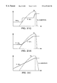
- the diodes at cross-sections AA′ and CC′ are represented generally by a diode 32 on the left side of FIG. 3 which shows a P or P+ region 33 , an N+ region 35 and an intervening N-epi layer 34 (referred to as a PN or PIN avalanche clamp).
- the thickness of the N-epi layer 34 is designated X epi (net).
- the electric field reaches a peak at the junction of P or P+ region 33 and N-epi layer 34 and then drops with increasing depth.
- the electric field (curve labeled PN) drops over a short distance; if N-epi layer 34 is lightly doped the electric field (curve labeled PIN(reachthrough)) is relatively flat indicating that the depletion region extends all the way to N+ substrate 35 ; if N-epi layer 34 is doped to an intermediate level the electric field (curve labeled P ⁇ N(reachthrough)) the depletion region again reaches through the entire N-epi layer 34 but the electric field is not flat across the entire layer 34 . Rather, in the last case the electric field slopes to some degree until it reaches the N+ region 35 .
- Neither the P or P+ region 33 nor the N+ region 35 can support any significant electric field. Since the breakdown voltage is roughly equal to the integral of the electric field over the interval X epi (net), it is apparent that the area under the triangle or trapezoid gives a rough estimate of the voltage of the device.
- the breakdown voltage is reduced.
- a thinner, more heavily doped epi layer has a lower resistance when the device is turned on.
- a variety of techniques have been used to optimize the device by fabricating the thinnest possible, most heavily doped epi-layer that still provides an adequate breakdown voltage. All of these variations are only a few percentage points apart in terms of what is needed to provide the optimal doping/thickness combination to meet and support the required breakdown voltage.
- FIG. 4 illustrates a graph that is available from many sources showing the “reach-through” breakdown voltage of a PIN diode as a function of the “background” doping concentration of the intermediate layer (C B ) for various intermediate layer thicknesses (designated as W EPI , which in this particular publication is equivalent to X epi (off) in FIGS. 1 and 2 ).
- the graph of FIG. 4 is taken from Semiconductor Technology Handbook, Technology Associates, page 8-9 (1980). If W EPI is an infinite thickness, there is a one-to-one correspondence between the background dopant concentration and the breakdown voltage. Since FIG. 4 is plotted on log-log paper, this implies a strong dependence between the dopant concentration and breakdown voltage.
- the breakdown voltage falls from about 300 V to about 15 V. If the intermediate layer is made thinner, then ultimately the breakdown voltage becomes independent of background concentration and varies only with the thickness of the intermediate layer. Between these extremes there is a region where the plots are curved, indicating that the breakdown voltage is a result of both the background concentration and intermediate layer thickness.
- the epi doping could be increased beyond 1.2 ⁇ 10 16 cm ⁇ 3 but the thickness would have to exceed 0.3 ⁇ m to meet a 60 V breakdown specification.
- E fepi off
- the dopant concentration would have to be designed to be in the range of 4 ⁇ 10 5 cm ⁇ 3 .
- Such a combination represents the points of the thinnest epi (2 ⁇ m) curve where the breakdown voltage does not vary substantially with doping. In this approach a 20% increase in resistivity at the thinnest (2 ⁇ m) epi would just barely meet the target breakdown voltage.
- FIG. 5 is a cross-section showing a portion of an N-epi layer 50 and an N+ substrate 51 .
- the upper boundary of N-epi layer 50 is designated X jB , and the thickness of N-epi layer 50 is X epi (on).
- R D A is the quantity (the specific on-resistance) that is to be minimized.
- the optimal solution yields a curve of E vs. ⁇ which is similar to the trapezoidal curve P ⁇ N(reachthrough) shown in FIG. 3 .
- the optimal breakdown voltage is in the range of 20-30 V/ ⁇ m, depending on the dopant concentration. If the silicon is doped more heavily and is thicker than the minimum reachthrough thickness, the breakdown voltage is closer to 30 V/ ⁇ m; if the silicon is doped more lightly the breakdown voltage is closer to 20 V/ ⁇ m.
- FIG. 6 shows curves for R D A both with and without the substrate. As expected, the values of the coefficients in an equation for ionization rate vary with the author and the fabricated devices.
- FIG. 7 shows pictorially the total drain-to-source resistance R DS in a planar DMOSFET.
- R channel is the channel resistance
- R JFET is the resistance in the JFET region where the current is squeezed between the depletion regions surrounding the body-drain junctions
- R spreading is the resistance in the region where the current is spreading out
- R epi is the resistance in the remainder of the epi layer
- R substrate is the resistance of the substrate.
- the total resistance of a trench-gated MOSFET is similar except that there is no R JFET .
- the trenchFET can be fabricated in higher cell densities than the planar DMOSFET. For example, the trenchFETs shown in FIGS.
- 9A and 9B which contain a central deep diffusion as taught in the above-referenced U.S. Pat. No. 5,072,266 to Bulucea et al., can be fabricated to a density of about 12 million cells per square inch. If the technique taught in the above-referenced application Ser. No. 08/459,555 is used the density can be increased to about 32 million cells per square inch.
- the critical parameter is the total channel width per unit area W/A (typically inverted as the packing coefficient A/W). Since the channel lies along the wall of the trench, the perimeter of each cell times the number of cells gives the total channel width.
- FIGS. 10A, 10 B and 10 C give the formulas for A/W for a trenchFET containing square, hexagonal and striped cells, respectively. Ysb is the length of a side of the cell and Yg is the length of the gate. In FIG. 10C, Z is the length of the stripe.
- A/W for the square and hexagonal cells is identical, and so long as the gate is smaller than the source-body region between the gates the square or hexagonal cell is better. Only if the regions between the gate are smaller than the gate is the striped configuration better.
- R DS A the normalized drain-to-source resistance R DS A is equal to the normalized channel resistance plus the normalized drain resistance (R JFET being zero).
- R D ⁇ ⁇ S ⁇ A R ch ⁇ W ⁇ A W + R D ⁇ A
- the channel resistance can be reduced by either thinning the gate oxide or improving A/W.
- R D A which is expressed as:
- R D A ⁇ x epi ⁇ epi +x sub ⁇ sub
- x epi and x sub represent the vertical distance through the epi layer and the substrate, respectively
- ⁇ epi and ⁇ sub represent the resistivity of the epi layer and substrate, respectively.
- ⁇ is a correction factor at account for current spreading in some portion of the epi layer.
- FIG. 11 is a graph showing the total normalized on-resistance as a function of the normalized gate oxide thickness for different levels of gate voltage in excess of the threshold voltage (V GS ⁇ Vt).
- the term (V GS ⁇ V t ) is useful to eliminate the influence of process parameters on the threshold voltage when comparing the performance of various devices. This “overdrive” keeps the voltage beyond threshold constant so that other terms can be separated for analysis. In so doing the resistance in the epi layer and substrate can be separated from the channel term as X OX ⁇ 0 and R Ch W ⁇ 0.
- the normalized resistance approaches a theoretical limit comprising the epi and substrate resistance which in this example is about 0.75 (i.e., 75%) of the total resistance of a reference device operated at a gate drive of 10 V above Vt, or around 12 V.
- the gate oxide thickness and cell density to minimize the channel resistance but the resistance of the epi layer and substrate remain.
- high voltage devices e.g., 500 V
- the cell density because so much of the resistance is attributable to the thick epi layer that is required to support a high breakdown voltage.
- Even for low voltage devices eventually one runs into the limit represented by the resistance of the epi layer and substrate. In every case eventually the epi resistance becomes the dominant factor.
- MOSFETs capable of handling voltages of 10 V up to 100 V or even 500 V and which have low on-resistances.
- MOSFET 120 is formed in a P-substrate or P-epi layer 121 and includes an N+ source 122 , an N+ drain 123 and a P+ body contact region 124 .
- a gate 125 is separated from a channel region by a gate oxide layer 126 .
- the gate 125 can vary from 0.25 to 20-30 ⁇ m in length, and the longer the channel the higher the on-resistance of the device. The on-resistance may be reduced by decreasing the gate oxide thickness, but eventually this is limited by the need to maintain a desired breakdown voltage.
- the gate oxide has to be kept above a minimal thickness (otherwise the oxide between the N+ drain and the gate oxide will rupture) or a lightly doped drain extension has to be interposed between the gate and drain. Since these devices are commonly used in logic circuits, the higher on-resistance and lower transconductance and consequent slower speeds that result from these techniques to achieve a higher breakdown voltage present problems. So aside from thinning the oxide, decreasing resistance and improving transconductance must be accomplished in another way.
- Layer 127 is a crystal that is a composite of silicon and germanium atoms wherein the germanium atoms might represent as much as 10% to 20% of the total number of atoms in the crystal lattice.
- Silicon and germanium are both Group IV elements and bond together covalently. For example, at a ratio of 10% one out of every ten atoms would be germanium and nine would be silicon.
- Layer 127 must be very thin—e.g., from 10 ⁇ to a few thousand ⁇ at most—and it is doped at a concentration which is much lower (e.g., 10 13 or 10 14 cm ⁇ 3 ) than the concentration of a typical channel region (e.g., 10 17 cm ⁇ 3 ).
- FIG. 13B shows a graph of a the doping concentration and percentage of germanium as a function of the depth below the surface.
- Si-Ge layer 127 which ideally is a lightly-doped layer.
- FIG. 13C is a diagram showing the lowest conduction band energy E c in the germanium and silicon regions. Highly doped regions generally have low carrier mobility because the charge carriers are more likely to collide with each other. This produces scattering and energy in the form of heat.
- the lightly doped Si-Ge layer owing to the lower dopant concentration, the mobility of the carriers is much greater than it is in the silicon.
- Si-Ge layer 127 functions as a tube or tunnel of very light dopant concentration which has a very high carrier mobility. The mobility of this layer is improved not only because of the presence of germanium (which has a higher mobility than silicon) but because the thin channel region is very lightly doped and therefore exhibits very little scattering due to interactions between the dopant (ions) and the channel carriers.
- Si-Ge layer 127 While numerous crystal defects are created by the mismatch between silicon and silicon-germanium, Si-Ge layer 127 is so thin that it is able to deform elastically to accommodate the more rigid underlying silicon. Si-Ge layer 127 must be very thin or the device will have a great deal of leakage and other undesirable properties. It should be noted that in the embodiment shown in FIGS. 13A-13C germanium is used to improve the channel mobility. This is an entirely different matter from the bulk drain resistance.
- FIG. 14 shows an HEMT 140 including an N-type polysilicon emitter 141 , a P-type base 142 , a Si-Ge layer 143 and an N-well 144 which serves as the collector of HEMT 140 .
- the on-state resistance of a transistor is reduced by forming a Si-Ge layer in the path of current flow (but outside the channel region).
- the Si-Ge layer reduces the on-resistance of the device without unduly affecting the breakdown voltage.
- the mole-fraction of germanium in the Si-Ge layer is typically in the range from about 5% to about 40%.
- One class of embodiments comprises vertical power MOSFETs, wherein a Si-Ge epitaxial (epi) layer is formed over a silicon substrate.
- the Si-Ge epi layer can extend to the top surface of the semiconductor material or it can be overlaid on a layer of silicon to prevent the deleterious effects of germanium getting incorporated into the gate oxide layer.
- the Si-Ge layer can have a uniform concentration or it can be graded or stepped to achieve desired characteristics.
- the vertical power MOSFET may take the form of a planar DMOSFET or a trench-gated MOSFET.
- a second class of embodiments include trench-gated MOSFETs which include a Si-Ge layer and may use the SiGe layer to determine the location of avalanche breakdown.
- a third class of embodiments include quasi-vertical devices in which the drain is represented by a buried layer that is linked to the surface by means of a vertical diffusion such as a sinker region.
- a fourth class of embodiments include lateral devices which include a Si-Ge layer that represents a relatively low-resistance path and diverts current from the normal current path.
- a Si-Ge layer according to this invention can also be used with other devices such as Schottky diodes, bipolar transistors, insulated gate bipolar transistors and thyristors.
- the Si-Ge layer can allow faster switching times and prevent latch-up, taking advantage of reduced minority carrier lifetimes.
- FIG. 1 shows a cross-sectional view of a conventional vertical planar DMOSFET.
- FIG. 2 shows a cross-sectional view of a conventional trench-gated MOSFET.
- FIG. 3 shows a cross-sectional view of a conventional PN or PIN avalanche clamping diode as well as a graph of the strength of the electric field in the diode.
- FIG. 4 illustrates a graph showing the reach-through breakdown voltage of a PIN diode as a function of the background doping concentration of the intermediate layer for various intermediate layer thicknesses.
- FIG. 5 is a cross-sectional view showing a portion of an N-epi layer and an N+ substrate.
- FIG. 6 is a graph which plots normalized on-resistance as a function of breakdown voltage for N-channel and P-channel devices.
- FIG. 7 shows pictorially the components of the total drain-to-source resistance in a planar DMOSFET.
- FIG. 8 shows pictorially the components of the total drain-to-source resistance in a trench-gated MOSFET.
- FIGS. 9A and 9B illustrate cross-sectional and plan views, respectively, of a MOSFET which contains a central deep diffusion as taught in U.S. Pat. No. 5,072,266.
- FIGS. 10A, 10 B and 10 C illustrate plan views of a trenchFET containing square, hexagonal and striped cells, respectively.
- FIG. 11 is a graph showing the total normalized on-resistance as a function of the normalized gate oxide thickness for different levels of gate voltage in excess of the threshold voltage (V GS ⁇ Vt).
- FIG. 12 shows a cross-sectional view of a lateral MOSFET.
- FIG. 13A shows a cross-sectional view of a lateral MOSFET containing a thin silicon-germanium layer immediately under the gate oxide layer.
- FIG. 13B shows a graph of a the doping concentration and percentage of germanium as a function of the depth below the surface in the MOSFET of FIG. 13 A.
- FIG. 13C is a diagram showing the lowest conduction band energy E c in the germanium and silicon regions in the MOSFET of FIG. 13 A.
- FIG. 14 shows a cross-sectional view of a high electron mobility bipolar transistor (HEMT).
- HEMT high electron mobility bipolar transistor
- FIG. 15 shows a graph of the mobility of silicon and germanium as a function of dopant concentration, for both N-type and P-type material.
- FIG. 16 shows a graph of the resistivity of various semiconductor materials as a function of impurity concentration.
- FIG. 17 shows a cross-sectional view of a planar DMOSFET which includes Si-Ge layer in accordance with this invention.
- FIG. 18 shows a cross-sectional view of a planar MOSFET similar to the MOSFET of FIG. 17 with an N-type silicon epi layer on top of the Si-Ge layer.
- FIG. 19 shows a cross-sectional view of a MOSFET similar to the MOSFET of FIG. 18 with a deep P+ diffusion extending below the P-body region to assure that voltage breakdown will not occur near the gate oxide layer.
- FIG. 20 shows a cross-sectional view of a MOSFET similar to the MOSFET of FIG. 19 wherein the deep P+ diffusion extends into the Si-Ge layer.
- FIGS. 21A-21I illustrate a variety of doping profiles that could be used in the MOSFETs shown in FIGS. 17-20, respectively.
- FIG. 22A shows a planar DMOSFET which includes a Si-Ge layer.
- FIG. 22B shows a graph of the profiles of the germanium and N-type dopant in the MOSFET shown in FIG. 22 A.
- FIG. 23 shows a cross-sectional view of a trenchFET which includes a Si-Ge layer.
- FIG. 24 shows a cross-sectional view of a trenchFET which includes a Si-Ge layer and a silicon epi layer which is divided into two sublayers.
- FIG. 25 shows a cross-sectional view of a trenchFET which is similar to the trenchFET shown in FIG. 24, except that the N+ source region extends across the entire mesa between the trenched gates
- FIG. 26 shows a cross-sectional view of an ACCUFET which contains a Si-Ge epi layer.
- FIGS. 27 and 28 show dopant profiles taken at two cross-sections of the ACCUFET shown in FIG. 26 .
- FIG. 29 shows a three-dimensional cross-section of the trenchFET shown in FIG. 25, illustrating how the P-body region may be contacted in a location away from the active areas of the device.
- FIG. 30A shows a cross-sectional view of a trenchFET which contains a Si-Ge layer and an N+ buried layer.
- FIG. 30B is a graph showing the dopant profiles of N+ buried layer, the N-epi layer, and N+ substrate and the Si-Ge layer in the trenchFET shown in FIG. 30 A.
- FIGS. 31A, 31 B and 31 C illustrate the steps of a process of fabricating a trenchFET similar to the trenchFET shown in FIG. 24 .
- FIG. 32 shows a cross-sectional view of a quasi-vertical DMOSFET containing an Si-Ge layer and an N buried layer which is linked to the surface by an N+ sinker.
- FIG. 33 shows a cross-sectional view of a lateral MOSFET with a Si-Ge layer and an N-epi layer grown on a P-type substrate.
- FIG. 34 illustrates a cross-sectional view of a lateral MOSFET which is similar to the MOSFET shown in FIG. 33 except that a P-type epi layer is grown over the P substrate.
- FIG. 35 shows a cross-sectional view of a classic lateral device that is similar to the MOSFET shown in FIG. 32 except that each stripe or cell of N+ source faces a stripe or cell of N+ drain.
- FIG. 36 shows a cross-sectional view of a Schottky diode which contains a Si-Ge layer in accordance with this invention.
- FIG. 37 shows a cross-sectional view of an insulated gate bipolar transistor (IGBT) a containing a Si-Ge layer.
- IGBT insulated gate bipolar transistor
- FIG. 38 shows a cross-sectional view of a bipolar transistor which contains a Si-Ge layer.
- FIG. 39A illustrates a vertical thyristor with a buried region of germanium.
- FIG. 39B illustrates a graph showing the concentrations of Si and Ge in the thyristor of FIG. 39 A.
- FIG. 15 shows a graph of the mobility of silicon and germanium as a function of dopant concentration, for both N-type and P-type material.
- N-type silicon has a mobility of about 700 cm 2 /volt-sec and P-type silicon has a mobility of about 350 cm 2 /volt-sec.
- N-type germanium has a mobility of about 3,000 cm 2 /volt-sec and P-type germanium has a mobility of about 900 cm 2 /volt-sec.
- this relationship between the mobility of silicon versus the mobility of germanium obtains at a variety of temperatures.
- the mobility and other factors that go into determining resistivity also give germanium an advantage over silicon.
- the resistivity of N-type silicon is approximately three times the resistivity of N-type germanium. So purely on the basis of mobility and resistivity, germanium is very attractive.
- germanium has a higher thermal conductivity which means that the junction temperature remains lower for equivalent levels of power dissipation.
- germanium has a number of defects which argue strongly against its use in power transistors.
- the oxide of germanium is chemically reactive (e.g, it is relatively water soluble) and it is electrically leaky.
- the critical electrical field i.e., the maximum limit beyond which breakdown will occur
- the energy gap of germanium is only 0.66 eV versus 1.12 eV for silicon at 300° K. These factors have an adverse effect on the breakdown voltage and on leakage, especially at high temperatures.
- the lattice constant of germanium (5.64613 ⁇ ) is quite similar to that of silicon (5.43095 ⁇ ), as are the number of atoms per cm 3 (4.42 ⁇ 10 22 for germanium, 5.0 ⁇ 10 22 for silicon). Inside a given layer these differences are still enough that if one has a large change of concentration numerous crystallographic defects can occur. A change in germanium concentration of 10% over a short distance can lead to excessive defects. If these defects are located in the channel region or near a peak field region of the device, the problem can be serious. Finally, the intrinsic carrier concentration of germanium is about three orders of magnitude higher than that of silicon (2.4 ⁇ 10 13 cm ⁇ 3 versus 1.45 ⁇ 10 10 cm ⁇ 3 ), leading to excessive current leakage particularly at high temperatures.
- germanium in the device can be overcome by including a Si-Ge layer, which contains a specified percentage of germanium atoms, typically from about 5% to about 40%.
- the layer can be formed by controlling the size of the concentration steps or gradient (e.g., by breaking a concentration step into smaller steps) so that defect generation during fabrication is minimal. Under such circumstances it is reasonable to assume that mobility is not adversely affected and that a low defect Si-Ge layer will have a mobility and resistivity somewhere between that of silicon and germanium.
- MOSFET is a planar DMOSFET which includes a silicon N+ substrate 11 and a Si-Ge epitaxial (epi) layer 171 doped with N-type impurity and grown on top of the silicon substrate 11 .
- Si-Ge layer 171 is typically 1 to 50 ⁇ m thick and typically includes from 5% to 30% or 40% (mole-fraction) germanium.
- Formed in the Si-Ge epi layer 171 are a P-body region 172 , a P+ body contact region 173 , and an N+ source region 174 .
- N+ source region 174 downward to the N+ substrate 11 (which functions as the drain) is controlled by a gate 175 which is separated from the channel region by a gate oxide layer 176 .
- the N+ substrate 11 is pure silicon, one could find a lot of defects at the interface between N+ substrate 11 and Si-Ge epi layer 171 . However, these defects are far away from the active regions of the device and are located in a region of relatively low electric field, and so long as the epi growth is done in a way that prevents the defects from propagating (e.g., by beginning the epi growth slowly and then increasing the rate of growth) the defects would be clustered around the substrate-epi interface but would not extend into the rest of the Si-Ge epi layer 171 .
- the updiffusing substrate dopants more than compensate for the region of the defects.
- One method of capturing and holding the defects in a specific region of high germanium content, especially for doses exceeding 1 ⁇ 10 15 cm ⁇ 2 is to precipitate oxygen onto the defects to create a permanent high-energy chemical bond through epitaxial or implantation means.
- the substrate oxygen initially in solution at 10 15 to 10 16 cm ⁇ 3 , is precipitated using a 500° C. to 800° C. oxidation. This oxygen in solution must come to equilibrium, especially if the furnace cycle is of limited temperature, for 8 to 15 hours. The oxygen will then cluster on the germanium defects and create semipermanent getter sites as long as the subsequent termperature cycles remain largely below 900° C.
- MOSFET 170 Because of the increased mobility of Si-Ge epi layer 171 MOSFET 170 has a significantly lower on-resistance than it would have if it were fabricated from pure silicon without an undue adverse effect on the breakdown voltage of the device.
- Si-Ge epi layer 171 extends to an interface with the gate oxide layer 176 .
- germanium may become incorporated into the gate oxide layer 176 in this embodiment, with the unfavorable effects on the reliability of the gate oxide layer discussed above.
- This problem could be overcome by keeping the germanium away from the gate oxide layer by forming a very thin layer of silicon on the surface. However, in some cases this may be difficult to accomplish.
- MOSFET 180 shown in FIG. 18 is similar to MOSFET 170 but an N-type silicon epi layer 187 is grown on top of Si-Ge epi layer 181 . This prevents any migration of germanium atoms into the gate oxide layer 186 . Silicon epi layer 187 is typically from 0.1 ⁇ m to 1-2 ⁇ m thick but could be as thick as 5 ⁇ m. The interface between Si-Ge epi layer 181 and silicon epi layer 187 would be formed by turning off the germanium source during the epi growth process. Nonetheless, at this interface there would be some crystallographic defects. Preferably, this interface is kept as far away from the PN body-to-drain junction as possible.
- MOSFET 190 shown in FIG. 19 is similar to MOSFET 180 , but a deep P+ diffusion 192 extends below the P-body region 191 to assure that voltage breakdown will not occur near the gate oxide layer and to suppress any significant NPN bipolar conduction.
- MOSFET 200 shown in FIG. 20 the deep P+ diffusion 202 extends into the Si-Ge epi layer 201 . While MOSFET 200 would have a lower breakdown voltage, the breakdown would be forced to occur away from the surface.
- running the PN body junction across the interface between Si-Ge epi layer 201 and Si epi layer 203 may increase the amount of current leakage in the device, particularly if the dopant concentrations in Si-Ge epi layer 201 and Si epi layer 203 are flat (i.e., independent of depth).
- FIGS. 21A-21I illustrate a variety of doping profiles that could be used in MOSFETs 170 , 180 , 190 and 200 shown in FIGS. 17-20, respectively.
- the doping profile is taken at a vertical section of the MOSFET that does not transect either the body or source regions, illustrated by cross-section EE′ in FIG. 17 .
- the solid line represents the concentration of N-type (donor) atoms and the dashed line represents the concentration of germanium atoms.
- FIGS. 21A-21C relate to MOSFET 17 , in which the Si-Ge layer 171 extends all the way to the surface of the semiconductor material.
- N+ substrate 11 is doped to 5 ⁇ 10 19 cm ⁇ 3 with N-type impurity and Si-Ge epi layer 171 is doped to 1 ⁇ 10 16 cm ⁇ 3 with N-type impurity, although the latter could be doped as heavily as 10 17 cm ⁇ 3 or as lightly as 10 14 cm ⁇ 3 , the actual level depending on the desired breakdown voltage.
- the germanium content in the N+ substrate 11 is very low but rises to 7 ⁇ 10 20 cm ⁇ 3 in epi layer 171 , which is equivalent to about 14% germanium.
- the percentage of germanium in epi layer 171 could be as high as about 40% or as low as about 5%.
- FIG. 21B shows the same N-type impurity levels, but the concentration of germanium atoms falls gradually as one approaches the semiconductor surface.
- the advantage of this structure is that, as shown in FIG. 3, the electric field is highest near the surface, where the germanium content is low and where the breakdown voltage is therefore closer to that of silicon. This particularly true for the PN and P ⁇ N junctions. As one moves deeper into the silicon, the germanium content becomes greater, taking advantage of a lower resistance where the electric field is weaker and where the breakdown voltage can therefore be lower.
- the germanium concentration increases in a stepwise fashion rather than gradually as one moves into the silicon.
- FIGS. 21D-21I relate to MOSFETs 180 , 190 and 200 , where the Si-Ge layer does not extend to the semiconductor surface.
- the N-type doping is similar to the profiles shown in FIGS. 21A-21C.
- the germanium content decreases quite abruptly whereas in FIG. 21E the germanium content decreases gradually, in both cases to zero.
- FIG. 21F the germanium content is similar to that shown in FIG. 21E, but a P-type region is formed near the surface.
- the P-type region could be, for example, a body region or the anode of a clamping diode.
- the germanium atoms are kept away from the PN junction.
- the germanium content is graded in the manner of FIGS. 21E and 21F, but the N-type impurity is varied.
- the N-type impurity is stepped downward, forming epi layers N-epi 1 and N-epi 2 .
- the N-type impurity is gradually reduced to a constant level in layer N-epi 2 .
- the N-type impurity is gradually reduced throughout the Si-Ge layer. In each case the N-type impurity might be at a concentration of more than 10 17 cm ⁇ 3 in the N+ substrate 11 and fall to 10 15 or 10 16 cm ⁇ 3 at the semiconductor surface.
- the N-type dopant concentration might fall from the high 10 14 s cm ⁇ 3 in N+ substrate 11 to the low 10 14 s cm ⁇ 3 or into the 10 13 cm ⁇ 3 range at the semiconductor surface.
- a very high-voltage (e.g., 500 V) device the N-type dopant concentration might fall from the high 10 14 s cm ⁇ 3 in N+ substrate 11 to the low 10 14 s cm ⁇ 3 or into the 10 13 cm ⁇ 3 range at the semiconductor surface.
- the germanium profile shown in any one of FIGS. 21A-21D could be substituted for that shown in FIGS. 21G-21I.
- One advantage of varying the germanium concentration in small increments or continuously in the process of growing the epi layer is that the stress from the addition of the germanium can be relieved gradually. In any event, subsequent thermal diffusion will tend to smooth out any small steps in the germanium profile.
- a rather sharp step increase deep in the epi layer, away from the active regions of the device would be acceptable so long as the crystallographic defects do not propagate extensively into the overlying material. In this case the defects would be concentrated in the vicinity of the step increase and should not materially affect the active regions of the device.
- the N+ substrate itself has a high defect count because of its degenerate doping concentration.
- the Si-Ge epi layer can be grown by including a source of germanium gas in the epi reactor.
- FIG. 22A shows a planar DMOSFET 220 which includes a Si-Ge epi layer 221 and a silicon epi layer 224 .
- MOSFET 220 includes a P-body region 222 and an N+ source region 223 .
- a submerged Si-Ge region 225 is formed in the center of the MOSFET directly underneath the gate by implanting germanium, either before or after the gate is formed.
- the Si-Ge region 225 is implanted after the P-body diffusion to prevent it from being diffused.
- FIG. 22B shows profiles of the germanium and N-type dopant in MOSFET 220 at the cross-section EE′ in FIG. 22 A.
- Si-Ge region 225 reduces the resistance to the current flowing downward in MOSFET 220 beyond the reduction that is achieved from Si-Ge epi layer 221 .
- the implant dose and energy may make this implementation difficult with present day equipment.
- the SiGe region 225 also helps to spread the drain current more evenly through the epi layer thereby improving the on-resistance.
- FIGS. 23-30 illustrate the application of the principles of this invention to a trench-gated MOSFET (trenchFET).
- trenchFET 230 shown in FIG. 23 a Si-Ge N-epi layer 231 is grown on N+ substrate 11 .
- the active area of the trenchFET are formed in a silicon N-epi layer 232 which is grown on top of Si-Ge N-epi layer 231 .
- the active area includes a gate 233 which is formed in a trench and separated from N-epi layer 232 by a gate oxide layer 234 .
- TrenchFET 230 also includes a P-body region 236 and an N+ source region 235 .
- a deep P+ diffusion at the center of the trenchFET cell assures that breakdown will occur away from the gate oxide layer in the manner taught in the above-referenced U.S. Pat. No. 5,072,266, except that the field concentration leading to avalanche is more prevalent with the defects and narrower bandgap of the silicon-germanium layer.
- TrenchFET 240 shown in FIG. 24 includes a Si-Ge epi layer 241 and a silicon epi layer which is divided into two sublayers 242 and 243 .
- Sublayer 243 is doped with N-type dopant to a higher concentration than sublayer 242 .
- a deep P+ diffusion 244 is formed in a separate diode cell 245 which is located on the opposite side of the gate from the trenchFET cell. Deep P+ diffusion 244 extends into silicon epi layer 242 .
- the PN junction between deep P+ diffusion 244 and silicon epi layer 242 forms a clamping diode which breaks down before any PN junction in the trenchFET cell, in the manner taught in application Ser. No. 08/495,555, except that the presence of the narrow bandgap silicon-germanium layer exacerbates the effect.
- TrenchFET 250 shown in FIG. 25 is similar to trenchFET 240 except that the N+ source region 251 extends across the entire mesa between the trenched gates.
- P-body region 252 can either be fully depleted in the manner taught in application Ser. No. 08/651,232, or P-body region 252 can be contacted at some location away from the cross-section shown in FIG. 25, as taught in application Ser. No. 08/460,336, now abandoned in favor of 08/884,826 filed on Jun. 30, 1997 and issued as U.S. Pat. No. 5,877,538 on Mar. 2, 1999.
- FIG. 26 shows an ACCUFET 260 similar to the one taught in application Ser. No. 08/459,559, now U.S. Pat. No. 5,661,322 issued on Aug. 26, 1997, which contains no P-body region for forming a MOSFET channel.
- N+ substrate 11 , Si-Ge epi layer 241 and silicon epi layers 242 and 243 are similar to the corresponding layers in trenchFET 250 .
- the mesa 261 between gates 262 is made narrow enough and gates 262 are doped such that current flow from the “source” 263 is pinched off when no bias is applied to gates 262 .
- the PN junction between deep P+ diffusion 264 and silicon N-epi layer 242 forms a clamping diode which is reverse-biased when ACCUFET 260 is operating with the N+ substrate 11 (drain) biased positive with respect to the N+ source 263 .
- This diode is designed to break down at a predetermined voltage and thereby prevent breakdown from occurring elsewhere in the ACCUFET 260 .
- FIGS. 27 and 28 show dopant profiles taken at cross-sections FF′ and GG′, respectively, in FIG. 26 .
- N-epi layer 243 (Nepi 1 ) is doped more lightly with N-type dopant than is N-epi layer 242 (Nepi 2 ).
- the deep P+ diffusion 264 extends entirely through Nepi 2 and into Nepi 1 . Whether P+ diffusion extends to the Si-Ge epi layer 241 is not particularly important, since the purpose is to lower the breakdown voltage.
- FIG. 29 shows a three-dimensional cross-section of trenchFET 250 (FIG. 25 ), illustrating how the P-body region 252 may be contacted via a P+ contact region 290 in a location away from the active areas of the device.
- FIG. 30A shows a technique for solving this problem in a trenchFET 300 which entails implanting an N+ buried layer 301 .
- N+ buried layer 301 diffuses upward to the bottom of the trenches and downward to merge with the N+ substrate 11 .
- the location of the Si-Ge epi layer 241 is not affected by the N+ buried layer 301 and remains away from the bottom of the trench.
- 30B is a graph showing the dopant profiles of N+ buried layer 301 , the N-epi layer, and N+ substrate 11 (solid lines) and the Si-Ge layer 241 (dashed lines) at cross-section HH′.
- the overlying P-type layers are excluded from the dopant profile.
- FIGS. 31A, 31 B and 31 C illustrate the steps of a process of fabricating a trenchFET similar to trenchFET 240 shown in FIG. 24 .
- the starting material is a N+ silicon substrate having a resistivity of roughly 3 m ⁇ -cm, although the resistivity could be as high as 5 m ⁇ -cm or as low as 1 m ⁇ -cm, and the crystal is of 100 orientation. (For a P-channel device a P+ substrate having roughly the same resistivity would be used.)
- an epitaxial layer is grown on the N+ substrate, starting with a germanium-silicon mixture and finishing with pure silicon, according to one of the dopant profiles shown above (e.g., in FIG. 27 ).
- the germanium source is turned off at a point from 1 ⁇ m to several ⁇ m below the level where the bottoms of the trenches will be placed.
- the Si-Ge Nepi 1 layer is doped to a concentration in accordance with the reachthrough breakdown curves of FIG. 4 or slightly lighter-for example, 3 ⁇ 10 14 cm ⁇ 3 for a 500 V device, 4 ⁇ 10 15 cm ⁇ 3 for a 60 V device, and 4 ⁇ 10 16 cm ⁇ 3 for a 20 V device.
- the silicon Nepi 2 layer is doped anywhere up to 90% of the preceding layer but typically about 70% of the preceding layer.
- a field oxide layer is then grown on the top epi layer.
- the N-epi layers may be stepped or graded, as described above.
- the field oxide layer is patterned to form an opening where the deep P+ diffusion will be located, using conventional photolithographic techniques.
- a thin oxide layer is grown in the opening.
- P-type atoms typically boron
- a predeposition of boron at 60 to 200 ⁇ /square could be employed.
- the substrate is patterned again and the trenches are formed by reactive ion etching to a depth of from 1.7 to 6 ⁇ m. Defects are then removed by oxidizing the surface at 900 or 1000° C.
- a sacrificial oxide layer from a few to 1000 A thick.
- the sacrificial oxide layer is removed and the gate oxide is grown, taking care that some source of chlorine such as HCl or trichloroethane (TCA), a volatile solvent which decomposes at elevated temperatures to facilitate a chlorine source for improved gate oxides, is present during the oxidation process to stabilize the oxide.
- the oxide-lined trenches are then filled with polysilicon which is doped with phosphorus at a dosage of 1 to 5 ⁇ 10 15 cm ⁇ 2 .
- the polysilicon could be doped by predeposition at 25 to 100 ⁇ /square.
- the polysilicon is then etched back to planarize the top surface. After the polysilicon gate has the top surface is subjected to an additional oxidation step to seal it, except in a region where a gate contact is to be formed.
- the P-body is then implanted at a dose of from 5 ⁇ 10 12 cm ⁇ 2 to 2 ⁇ 10 14 cm ⁇ 2 and at an energy of 60 to 120 keV, either through a mask or by performing a blanket implant, resulting in a peak concentration of 5 ⁇ 10 15 cm ⁇ 3 to 8 ⁇ 10 16 cm ⁇ 3 .
- the P-body implant is typically diffused to a level 0.3 or 0.4 ⁇ m above the bottom of the trenches.
- the N+ source is implanted using arsenic (or phosphorus) at a dose of 5 ⁇ 10 15 cm ⁇ 2 to 1 ⁇ 10 16 cm ⁇ 2 at 20 to 100 keV.
- the shallow P+ region is implanted at a dose or energy which provides a lower surface concentration than the N+ region so that the two regions can overlap.
- the P+ region may therefore be implanted as a blanket implant, without a mask, if so desired.
- the dose of the P+ region is typically 5 ⁇ 10 14 to 2 ⁇ 10 15 cm ⁇ 2 at an energy of up to 120 keV. In a P-channel device the P+ dose is higher, in the range of 1 ⁇ 10 15 to 8 ⁇ 10 15 cm ⁇ 2 and the dose of the N+ implant is lowered somewhat.
- a final oxide layer is then formed by chemical vapor deposition (CVD) to a thickness of from 0.1 to 1 ⁇ m and patterned to create openings where the metal interconnect will contact the N+ source, P-body and deep P+ diffusion.
- the P+ regions may be implanted through the windows in the contact mask.
- the metal layer is then deposited followed by a passivation layer of borophosphosilicate glass or silicon nitride.
- FIGS. 32-38 illustrate cross-sectional views of other devices which can use a Si-Ge layer to reduce resistance.
- FIG. 32 shows a quasi-vertical DMOSFET 320 containing an N buried layer 321 which is linked to the surface by an N+ sinker 322 . The drain contact is made to the N+ sinker 322 .
- the N buried layer is formed by implanting N-type dopant into the P substrate and then allowing the N-type dopant to diffuse upward as the epi layers are grown.
- the Si-Ge epi layer 324 is formed in the manner described above.
- FIG. 33 shows a lateral MOSFET 330 with an N-epi layer 331 grown on a P-type substrate 332 .
- a Si-Ge layer 333 is formed as described above.
- the N-type dopant concentration in the epi layer 331 is chosen for a given breakdown or on-resistance or it could be optimized using the resurf or lateral charge control principle so that the integrated charge of the N-epi layer 331 is roughly in the range of 1 to 3 ⁇ 10 12 cm ⁇ 2 in the drift region (the N-type layer between the bottom of the oxide layer 337 and the top of the P-buried layer 338 or the P-substrate 332 ).
- Si-Ge layer 333 helps to reduce the lateral on-resistance and yet it is held below the surface and stays out of the P-body region and the gate oxide 335 .
- the gate 336 steps over a field oxide region 337 in the manner common in power devices.
- MOSFET 330 the current flowing between the N+ source region 334 B and the N+ drain region 334 C tends to be diverted downward into the Si-Ge layer 333 where the resistance is lower than in the remainder of the N-epi 331 layer. Because the Si-Ge layer 333 is held away from the surface it does not adversely influence hot carrier generation near the silicon surface of the thin gate region interposed between P-body region and the field oxide region 337 .
- MOSFET 330 starts with P substate 332 which is doped with boron to 1 to 3 ⁇ -cm.
- a P buried layer 338 is formed by implanting boron at 1 ⁇ 10 14 cm ⁇ 2 to 5 ⁇ 10 15 cm ⁇ 2 and at 20 to 120 keV.
- N-epi layer 331 is grown to a thickness of from 1 ⁇ m to 20 or 30 ⁇ m (typically 3 to 5 ⁇ m), with part of the layer including germanium to form the Si-Ge layer 333 .
- N-epi layer 331 and the doping of the P-substrate 332 form a two-sided step junction which determines the maximum breakdown voltage between the drain 334 C and the P-well 339 with P-substrate 332 .
- the thickness of N-epi layer 331 has a second order effect, however, so long as the dopant level is chosen to deplete before it avalanches, since MOSFET 330 uses a charge control principle. To maintain lateral charge control the following relationship must be maintained:
- field oxide layer 337 is grown to a thickness of about 0.5 ⁇ m, although it could be as thick as 2 ⁇ m or as thin as 0.3 ⁇ m.
- Field oxide layer 331 is formed by oxidizing between 30 minutes and 5 hours at 900 to 1100° C. in an oxygen or steam environment. Then field oxide layer 337 is patterned.
- a LOCOS process is used to form field oxide layer 337 : growing a thin oxide layer, depositing and patterning a 0.5 ⁇ m thick nitride layer, growing the oxide in the exposed areas and stripping the nitride.
- gate oxide layer 335 is formed to a thickness of from 100 to 1000 Angstroms by oxidizing the silicon surface in dry oxygen at 850 to 1100° C. from 30 minutes to 5 hours (typically from 900 to 1000° C. for a thickness of from 175 to 400 Angstroms). Then the polysilicon gate 336 is deposited, doped with N-type dopant as described above, and patterned. The surface is masked with photoresist to implant the P-body region 334 in selected regions at a dose of 5 ⁇ 10 13 cm ⁇ 2 to 2 ⁇ 10 14 cm ⁇ 2 for 2 to 14 hours at 1050 to 1200° C.
- a subsequent mask is used for the P+ body contact region 334 A which is implanted at a dose of 8 ⁇ 10 14 cm ⁇ 2 to 3 ⁇ 10 15 cm ⁇ 2 at 20 to 100 keV (typically 60 keV).
- the N+ source 334 B region and the N+ drain reion 334 C are implanted with arsenic at a dose of 5 ⁇ 10 15 cm ⁇ 2 (possibly as high as 1 ⁇ 10 16 cm ⁇ 2 ) and at 60 to 100 keV.
- N+ source region 334 B is self-aligned to the gate 336 and N+ drain region 334 C is self-aligned to the field oxide layer 337 .
- the device is heated at 900° C.
- a layer of borophosphosilicate glass (BPSG) is deposited to a thickness of 0.3 to 1.5 ⁇ m (typically 0.6 ⁇ m) and etched to create openings for the metal interconnect layers. Subsequently, one, two or three layers of metal interconnect are deposited, separated by intervening layers of BPSG or undoped glass.
- the BPSG or glass layers can be spun on or deposited by CVD.
- FIG. 34 illustrates a lateral MOSFET 340 which is similar except that in this embodiment a P-type epi layer 341 is grown over the P substrate 332 .
- the function of the P buried layer 338 is still to shape the electric field, but an N-type lightly-doped drain region 342 is formed not with the growth of the epi layer but by implantation.
- Region 342 tightly hugs the bottom of the field oxide region 337 and the current flows through the channel region in the P-body region 334 and the Si-Ge layer 333 and into the lightly-doped drain region 342 .
- the Si-Ge layer 333 extends up into the lightly-doped drain region 342 , so the germanium is closer to the surface and must be controlled so that it does not get into the gate oxide 335 .
- field oxide region 337 may be made thin so that the polysilicon gate remains flat without the oxide step.
- MOSFET 350 shown in FIG. 35 is a classic lateral device that is similar to MOSFET 320 shown in FIG. 32 except that instead of having many vertical cells and a single N+ sinker to provide a drain contact each stripe or cell of N+ source (such as N+ source region 351 ) faces a stripe or cell of N+ drain (such as N+ drain region 352 ).
- This structure is repeated in a regular pattern across the chip so that the current is always flowing to a separate drain contact.
- a multi-level metal interconnect structure is required to connect the drain and source regions.
- Si-Ge layer 353 operates in a manner similar to Si-Ge layer 324 in MOSFET 320 to divert the current to a region of lower resistivity.
- FIG. 36 shows a Schottky diode 360 with a P+ guard ring 361 which protects a rectifying interface 362 between a metal layer 363 (e.g., platinum, titanium, or tungsten or a silicide of one of the foregoing metals) and a lightly-doped N-epi layer 364 .
- a Si-Ge layer 365 is formed on top of an N+ substrate 366 to reduce the on-resistance of the device.
- the insulated gate bipolar transistor (IGBT) 370 shown in FIG. 37 is a high-voltage device which would typically have very thick layers and would be capable of withstanding 500-1000 V.
- Si-Ge layer 371 is preferably graded to prevent high electric fields from occurring near the surface.
- IGBT has a P+ substrate 372 that forms a diode with the N-buffer layer 373 . This diode becomes forward-biased when the device is turned on and injects holes into N-regions, thereby modulating the conductivity and reducing the on-resistance of the device.
- the Si-Ge layer 371 further reduces the on-resistance.
- N-buffer layer 373 helps to suppress the snapback characteristic of the parasitic PNP bipolar transistor consisting of the P+ substrate 372 , the N-buffer 373 and N-epi layer 374 , and the P-body region 375 and also improves the punchthrough characteristic and controls the gain.
- the defects that may be present along the interfaces with the Si-Ge layer 371 can be beneficial in that when the device is turned off they will help promote additional recombination and will thereby reduce the turn-off time of the device as compared with a device which does not include a Si-Ge layer. So IGBT 370 simultaneously provides a reduced on-resistance and reduced turn-off time.
- IGBT 370 could also be fabricated as a P-channel device, or without a gate as a silicon-controlled rectifier (SCR) or thyristor.
- FIG. 38 shows the use of a Si-Ge layer 381 in a bipolar transistor 380 .
- Bipolar transistor 380 has a significant resistance in its N-epi region 382 which is reduced by the Si-Ge layer 381 .
- the Si-Ge layer could extend all the way to the surface of the device because there is no gate oxide layer. However, this could cause some current leakage, so it is probably a better practice to keep the Si-Ge layer 381 out of the P-base 383 .
- a Si-Ge layer could be used in devices that go up to 2000-3000 V.
- a PNPN thyristor By adding a P+ substrate on the backside, a PNPN thyristor can be formed, as shown in FIG. 39 A.
- Significant conduction occurs by holes in the PNP bipolar transistor formed by the backside P+, the N-epi and the P-base.
- the collected holes flowing in the base region create a voltage drop and allow the N+ regions to become forward-biased and to inject electrons into the P-base which are subsequently collected by the N-epi layer.
- the collector current (N-epi) of the NPN feeds the base of the PNP.
- the collector current of the PNP feeds the base of the NPN.
- the 4-layer sandwich becomes flooded with holes and electrons across the entire epi and P-base region whereby the device latches into an on state.
- FIG. 39B is a graph showing the concentration of silicon and germanium atoms in a vertical section of the device.
- Si-Ge layer may have the added benefit of reducing the turn-off time when they are commutating and decrease the chances of latch-up.
- a switched thyristor which is intended to latch on such as a gate turnoff thyristor (GTO) or an emitter-switched thyristor (EST)
- GTO gate turnoff thyristor
- EST emitter-switched thyristor
- the Si-Ge layer may allow the control current to be greater, but the change in the on-resistance will not be as beneficial because these devices are so heavily conductivity-modulated that the Si-Ge layer will not change the voltage drop much, especially since an IGBT has a voltage drop in series with a device that has to be overcome before the device can begin to conduct.
- the Si-Ge layer may assist more with the switching characteristic than with the on-state voltage drop.
- Germanium has a different band gap and a different work function than silicon. Thus there is a built-in energy difference between pure silicon and a combination of silicon and germanium. As the content of the germanium in the Si-Ge layer increases the height of the energy barrier represented by the Si-Ge layer increases and this energy barrier eventually begins to suppress conduction across the barrier and the on-state voltage drop across the device begins to increase rather than decrease. It is currently believed that this phenomenon sets an upper limit in the range of 35-40% germanium. The liklihood is that this is not the effective upper limit for germanium content because the problem of defects in the crystalline structure probably will occur before the energy barrier problem, although in time materials engineering and process technology may surmount the difficulties with process-induced defects.
Abstract
Description


Claims (60)
Priority Applications (1)
| Application Number | Priority Date | Filing Date | Title |
|---|---|---|---|
| US08/919,386 US6239463B1 (en) | 1997-08-28 | 1997-08-28 | Low resistance power MOSFET or other device containing silicon-germanium layer |
Applications Claiming Priority (1)
| Application Number | Priority Date | Filing Date | Title |
|---|---|---|---|
| US08/919,386 US6239463B1 (en) | 1997-08-28 | 1997-08-28 | Low resistance power MOSFET or other device containing silicon-germanium layer |
Publications (1)
| Publication Number | Publication Date |
|---|---|
| US6239463B1 true US6239463B1 (en) | 2001-05-29 |
Family
ID=25441987
Family Applications (1)
| Application Number | Title | Priority Date | Filing Date |
|---|---|---|---|
| US08/919,386 Expired - Lifetime US6239463B1 (en) | 1997-08-28 | 1997-08-28 | Low resistance power MOSFET or other device containing silicon-germanium layer |
Country Status (1)
| Country | Link |
|---|---|
| US (1) | US6239463B1 (en) |
Cited By (128)
| Publication number | Priority date | Publication date | Assignee | Title |
|---|---|---|---|---|
| US20020030191A1 (en) * | 1998-08-28 | 2002-03-14 | Das Mrinal Kanti | High voltage, high temperature capacitor structures and methods of fabricating same |
| US20020038891A1 (en) * | 2000-10-03 | 2002-04-04 | Sei-Hyung Ryu | Silicon carbide power metal-oxide semiconductor field effect transistors having a shorting channel and methods of fabricating silicon carbide metal-oxide semiconductor field effect transistors having a shorting channel |
| US6404011B2 (en) * | 1998-10-28 | 2002-06-11 | Electronics And Telecommunications Research Institute | Semiconductor power integrated circuit |
| US20020072247A1 (en) * | 2000-10-03 | 2002-06-13 | Lipkin Lori A. | Method of N2O growth of an oxide layer on a silicon carbide layer |
| US6504230B2 (en) * | 1999-09-07 | 2003-01-07 | Infineon Technologies Ag | Compensation component and method for fabricating the compensation component |
| US6521951B2 (en) * | 1999-07-23 | 2003-02-18 | Mitsubishi Denki Kabushiki Kaisha | Semiconductor circuit device with improved surge resistance |
| EP1294025A2 (en) * | 2001-09-11 | 2003-03-19 | Sarnoff Corporation | Scr electrostatic discharge protection for integrated circuits |
| US6586798B1 (en) * | 1998-12-09 | 2003-07-01 | Stmicroelectronics S.R.L. | High voltage MOS-gated power device |
| WO2003085722A2 (en) * | 2002-03-29 | 2003-10-16 | Fairchild Semiconductor Corporation | Field effect transistor having a lateral depletion structure |
| US20030219945A1 (en) * | 2002-05-22 | 2003-11-27 | Sun-Hak Lee | Vertical double diffused MOSFET and method of fabricating the same |
| US20030218210A1 (en) * | 2002-05-21 | 2003-11-27 | Fuji Electric Co., Ltd. | Semiconductor device |
| US6686625B2 (en) * | 2000-12-05 | 2004-02-03 | Infineon Technologies Ag | Field effect-controllable semiconductor component with two-directional blocking, and a method of producing the semiconductor component |
| US20040067609A1 (en) * | 2002-10-07 | 2004-04-08 | Jian-Hsing Lee | Silicon controlled rectifier for sige process, manufacturing method thereof and integrated circuit including the same |
| US6730606B1 (en) * | 2000-11-03 | 2004-05-04 | Semiconductor Components Industries, L.L.C. | Trench growth techniques using selective epitaxy |
| US20040101625A1 (en) * | 2002-08-30 | 2004-05-27 | Das Mrinal Kanti | Nitrogen passivation of interface states in SiO2/SiC structures |
| US20040119076A1 (en) * | 2002-12-20 | 2004-06-24 | Sei-Hyung Ryu | Vertical JFET limited silicon carbide power metal-oxide semiconductor field effect transistors and methods of fabricating vertical JFET limited silicon carbide metal- oxide semiconductor field effect transistors |
| US20040132252A1 (en) * | 2001-01-30 | 2004-07-08 | Merchant Bruce D. | Method of forming a field effect transistor having a lateral depletion structure |
| US20040141537A1 (en) * | 2000-07-14 | 2004-07-22 | Matsushita Electric Industrial Co., Ltd. | Light-emitting device and optical integrated device |
| US20040212011A1 (en) * | 2003-04-24 | 2004-10-28 | Sei-Hyung Ryu | Silicon carbide mosfets with integrated antiparallel junction barrier schottky free wheeling diodes and methods of fabricating the same |
| US20040211980A1 (en) * | 2003-04-24 | 2004-10-28 | Sei-Hyung Ryu | Silicon carbide power devices with self-aligned source and well regions and methods of fabricating same |
| US20050139914A1 (en) * | 2003-12-19 | 2005-06-30 | Third Dimension (3D) Semiconductor, Inc. | Method for forming thick dielectric regions using etched trenches |
| US20050176192A1 (en) * | 2003-12-19 | 2005-08-11 | Third Dimension (3D) Semiconductor, Inc. | Planarization method of manufacturing a superjunction device |
| US20050181577A1 (en) * | 2003-12-19 | 2005-08-18 | Third Dimension (3D) Semiconductor, Inc. | Method of manufacturing a superjunction device |
| US20050181564A1 (en) * | 2003-12-19 | 2005-08-18 | Third Dimension (3D) Semiconductor, Inc. | Method for manufacturing a superjunction device with wide mesas |
| US20050181558A1 (en) * | 2003-12-19 | 2005-08-18 | Third Dimension (3D) Semiconductor, Inc. | Method of manufacturing a superjunction device with conventional terminations |
| US20050230675A1 (en) * | 2003-12-05 | 2005-10-20 | Kabushiki Kaisha Toshiba | Field-effect transistor, semiconductor device, and photo relay |
| US7015104B1 (en) | 2003-05-29 | 2006-03-21 | Third Dimension Semiconductor, Inc. | Technique for forming the deep doped columns in superjunction |
| EP1655784A2 (en) * | 2004-10-29 | 2006-05-10 | Sharp Kabushiki Kaisha | Trench MOSFET and method of manufacturing the same |
| US7067176B2 (en) | 2000-10-03 | 2006-06-27 | Cree, Inc. | Method of fabricating an oxide layer on a silicon carbide layer utilizing an anneal in a hydrogen environment |
| US20060166417A1 (en) * | 2005-01-27 | 2006-07-27 | International Business Machines Corporation | Transistor having high mobility channel and methods |
| US7118970B2 (en) | 2004-06-22 | 2006-10-10 | Cree, Inc. | Methods of fabricating silicon carbide devices with hybrid well regions |
| US20060226494A1 (en) * | 2004-12-27 | 2006-10-12 | Third Dimension (3D) Semiconductor, Inc. | Tungsten plug drain extension |
| US20060231915A1 (en) * | 2004-12-27 | 2006-10-19 | Third Dimension (3D) Semiconductor, Inc. | Process for high voltage superjunction termination |
| US20060261348A1 (en) * | 2005-05-18 | 2006-11-23 | Sei-Hyung Ryu | High voltage silicon carbide devices having bi-directional blocking capabilities and methods of fabricating the same |
| US20060261346A1 (en) * | 2005-05-18 | 2006-11-23 | Sei-Hyung Ryu | High voltage silicon carbide devices having bi-directional blocking capabilities and methods of fabricating the same |
| US20060261345A1 (en) * | 2005-05-18 | 2006-11-23 | Sei-Hyung Ryu | High voltage silicon carbide devices having bi-directional blocking capabilities and methods of fabricating the same |
| US20060292805A1 (en) * | 2005-06-27 | 2006-12-28 | Kabushiki Kaisha Toshiba | Semiconductor device |
| US20070063217A1 (en) * | 2005-08-22 | 2007-03-22 | Icemos Technology Corporation | Bonded-wafer Superjunction Semiconductor Device |
| EP1772906A1 (en) * | 2005-09-09 | 2007-04-11 | ATMEL Germany GmbH | High-voltage field-effect transistor and method of making a high-voltage field-effect transistor |
| US7259411B1 (en) * | 2003-12-04 | 2007-08-21 | National Semiconductor Corporation | Vertical MOS transistor |
| US20070210376A1 (en) * | 2006-03-10 | 2007-09-13 | Chartered Semiconductor Manufacturing Ltd. | Integrated circuit system with double doped drain transistor |
| US20070252174A1 (en) * | 2006-04-28 | 2007-11-01 | Nissan Motor Co., Ltd. | Method of manufacturing semiconductor device and semiconductor device |
| US20080023796A1 (en) * | 2006-07-28 | 2008-01-31 | Sanyo Electric Co., Ltd. | Semiconductor device and method of manufacturing the same |
| US20080042165A1 (en) * | 2006-08-02 | 2008-02-21 | Sony Corporation | Semiconductor device and method for manufacturing semiconductor device |
| US20080105949A1 (en) * | 2006-08-17 | 2008-05-08 | Cree, Inc. | High power insulated gate bipolar transistors |
| US20080191248A1 (en) * | 2007-02-09 | 2008-08-14 | Qi Wang | Scalable Power Field Effect Transistor with Improved Heavy Body Structure and Method of Manufacture |
| US7414268B2 (en) | 2005-05-18 | 2008-08-19 | Cree, Inc. | High voltage silicon carbide MOS-bipolar devices having bi-directional blocking capabilities |
| US20080258239A1 (en) * | 2007-04-23 | 2008-10-23 | Icemos Technology Corporation | Methods for manufacturing a trench type semiconductor device having a thermally sensitive refill material |
| US20090026586A1 (en) * | 2005-04-22 | 2009-01-29 | Icemos Technology Corporation | Superjunction Device Having Oxide Lined Trenches and Method for Manufacturing a Superjunction Device Having Oxide Lined Trenches |
| US20090085148A1 (en) * | 2007-09-28 | 2009-04-02 | Icemos Technology Corporation | Multi-directional trenching of a plurality of dies in manufacturing superjunction devices |
| US7528040B2 (en) | 2005-05-24 | 2009-05-05 | Cree, Inc. | Methods of fabricating silicon carbide devices having smooth channels |
| WO2009076362A1 (en) * | 2007-12-13 | 2009-06-18 | Fairchild Semiconductor Corporation | Structure and method for forming field effect transistor with low resistance channel region |
| US20090200608A1 (en) * | 2001-10-26 | 2009-08-13 | Renesas Technology Corp. | Semiconductor device |
| US20090315036A1 (en) * | 2006-08-01 | 2009-12-24 | Qingchun Zhang | Semiconductor devices including schottky diodes having doped regions arranged as islands and methods of fabricating same |
| US7652326B2 (en) | 2003-05-20 | 2010-01-26 | Fairchild Semiconductor Corporation | Power semiconductor devices and methods of manufacture |
| US7655981B2 (en) | 2003-11-28 | 2010-02-02 | Fairchild Korea Semiconductor Ltd. | Superjunction semiconductor device |
| WO2010027548A1 (en) * | 2008-09-05 | 2010-03-11 | Freescale Semiconductor Inc. | Power mosfet with a gate structure of different material |
| US20100065946A1 (en) * | 2008-03-28 | 2010-03-18 | Icemos Technology Ltd. | Bonded Wafer Substrate for Use in MEMS Structures |
| US7723172B2 (en) | 2007-04-23 | 2010-05-25 | Icemos Technology Ltd. | Methods for manufacturing a trench type semiconductor device having a thermally sensitive refill material |
| US7727904B2 (en) | 2005-09-16 | 2010-06-01 | Cree, Inc. | Methods of forming SiC MOSFETs with high inversion layer mobility |
| US7732876B2 (en) | 2004-08-03 | 2010-06-08 | Fairchild Semiconductor Corporation | Power transistor with trench sinker for contacting the backside |
| US20100140628A1 (en) * | 2007-02-27 | 2010-06-10 | Qingchun Zhang | Insulated gate bipolar transistors including current suppressing layers |
| US7745289B2 (en) | 2000-08-16 | 2010-06-29 | Fairchild Semiconductor Corporation | Method of forming a FET having ultra-low on-resistance and low gate charge |
| US7772668B2 (en) | 2007-12-26 | 2010-08-10 | Fairchild Semiconductor Corporation | Shielded gate trench FET with multiple channels |
| US20100244047A1 (en) * | 2009-03-27 | 2010-09-30 | Cree, Inc. | Methods of Forming Semiconductor Devices Including Epitaxial Layers and Related Structures |
| US20100283529A1 (en) * | 2009-05-08 | 2010-11-11 | Cree, Inc. | Wide bandgap bipolar turn-off thyristor having non-negative temperature coefficient and related control circuits |
| US20100301335A1 (en) * | 2009-06-02 | 2010-12-02 | Sei-Hyung Ryu | High Voltage Insulated Gate Bipolar Transistors with Minority Carrier Diverter |
| US7846821B2 (en) | 2008-02-13 | 2010-12-07 | Icemos Technology Ltd. | Multi-angle rotation for ion implantation of trenches in superjunction devices |
| US7859047B2 (en) | 2006-06-19 | 2010-12-28 | Fairchild Semiconductor Corporation | Shielded gate trench FET with the shield and gate electrodes connected together in non-active region |
| US20110012130A1 (en) * | 2009-07-15 | 2011-01-20 | Qingchun Zhang | High Breakdown Voltage Wide Band-Gap MOS-Gated Bipolar Junction Transistors with Avalanche Capability |
| WO2011024549A1 (en) * | 2009-08-31 | 2011-03-03 | 日本電気株式会社 | Semiconductor device and field effect transistor |
| US7936008B2 (en) | 2003-12-30 | 2011-05-03 | Fairchild Semiconductor Corporation | Structure and method for forming accumulation-mode field effect transistor with improved current capability |
| US7977744B2 (en) | 2002-07-18 | 2011-07-12 | Fairchild Semiconductor Corporation | Field effect transistor with trench filled with insulating material and strips of semi-insulating material along trench sidewalls |
| CN102142375A (en) * | 2010-12-29 | 2011-08-03 | 上海贝岭股份有限公司 | Manufacturing method of plane type field controlled power device |
| US20110241170A1 (en) * | 2009-01-27 | 2011-10-06 | Infineon Technologies Austria Ag | Monolithic semiconductor switches and method for manufacturing |
| US20110278642A1 (en) * | 2010-05-13 | 2011-11-17 | Great Power Semiconductor Corp. | Power semiconductor structure with field effect rectifier and fabrication method thereof |
| US8084327B2 (en) | 2005-04-06 | 2011-12-27 | Fairchild Semiconductor Corporation | Method for forming trench gate field effect transistor with recessed mesas using spacers |
| CN101771098B (en) * | 2005-10-03 | 2012-01-11 | 夏普株式会社 | Silicon-based thin film photoelectric converter, and method and apparatus for manufacturing same |
| US20120049902A1 (en) * | 2010-08-30 | 2012-03-01 | Stmicroelectronics S.R.L. | Integrated electronic device and method for manufacturing thereof |
| US8193848B2 (en) | 2009-06-02 | 2012-06-05 | Cree, Inc. | Power switching devices having controllable surge current capabilities |
| US8198677B2 (en) | 2002-10-03 | 2012-06-12 | Fairchild Semiconductor Corporation | Trench-gate LDMOS structures |
| US20120248531A1 (en) * | 2011-03-31 | 2012-10-04 | Semiconductor Components Industries, L.L.C. | Insulated gate semiconductor device |
| US8319290B2 (en) | 2010-06-18 | 2012-11-27 | Fairchild Semiconductor Corporation | Trench MOS barrier schottky rectifier with a planar surface using CMP techniques |
| US8354690B2 (en) | 2009-08-31 | 2013-01-15 | Cree, Inc. | Solid-state pinch off thyristor circuits |
| US8415671B2 (en) | 2010-04-16 | 2013-04-09 | Cree, Inc. | Wide band-gap MOSFETs having a heterojunction under gate trenches thereof and related methods of forming such devices |
| US8432012B2 (en) | 2006-08-01 | 2013-04-30 | Cree, Inc. | Semiconductor devices including schottky diodes having overlapping doped regions and methods of fabricating same |
| US8618582B2 (en) | 2011-09-11 | 2013-12-31 | Cree, Inc. | Edge termination structure employing recesses for edge termination elements |
| US8653534B2 (en) | 2008-05-21 | 2014-02-18 | Cree, Inc. | Junction Barrier Schottky diodes with current surge capability |
| US8653590B2 (en) | 2010-08-30 | 2014-02-18 | Stmicroelectronics S.R.L. | Vertical-conduction integrated electronic device and method for manufacturing thereof |
| US8664665B2 (en) | 2011-09-11 | 2014-03-04 | Cree, Inc. | Schottky diode employing recesses for elements of junction barrier array |
| US8673700B2 (en) | 2011-04-27 | 2014-03-18 | Fairchild Semiconductor Corporation | Superjunction structures for power devices and methods of manufacture |
| US8680587B2 (en) | 2011-09-11 | 2014-03-25 | Cree, Inc. | Schottky diode |
| US8772868B2 (en) | 2011-04-27 | 2014-07-08 | Fairchild Semiconductor Corporation | Superjunction structures for power devices and methods of manufacture |
| US8786010B2 (en) | 2011-04-27 | 2014-07-22 | Fairchild Semiconductor Corporation | Superjunction structures for power devices and methods of manufacture |
| US8836028B2 (en) | 2011-04-27 | 2014-09-16 | Fairchild Semiconductor Corporation | Superjunction structures for power devices and methods of manufacture |
| US8921935B2 (en) | 2011-01-12 | 2014-12-30 | Samsung Electronics Co., Ltd. | Semiconductor device |
| US8928077B2 (en) | 2007-09-21 | 2015-01-06 | Fairchild Semiconductor Corporation | Superjunction structures for power devices |
| US8946814B2 (en) | 2012-04-05 | 2015-02-03 | Icemos Technology Ltd. | Superjunction devices having narrow surface layout of terminal structures, buried contact regions and trench gates |
| US20150084063A1 (en) * | 2013-09-20 | 2015-03-26 | Cree, Inc. | Semiconductor device with a current spreading layer |
| US9018635B2 (en) | 2010-08-30 | 2015-04-28 | Stmicroelectronics S.R.L. | Integrated electronic device with edge-termination structure and manufacturing method thereof |
| US20150116031A1 (en) * | 2013-10-30 | 2015-04-30 | Infineon Technologies Austria Ag | Semiconductor Device and Integrated Apparatus Comprising the same |
| US20150118810A1 (en) * | 2013-10-24 | 2015-04-30 | Madhur Bobde | Buried field ring field effect transistor (buf-fet) integrated with cells implanted with hole supply path |
| US9029945B2 (en) | 2011-05-06 | 2015-05-12 | Cree, Inc. | Field effect transistor devices with low source resistance |
| US9117739B2 (en) | 2010-03-08 | 2015-08-25 | Cree, Inc. | Semiconductor devices with heterojunction barrier regions and methods of fabricating same |
| US9142662B2 (en) | 2011-05-06 | 2015-09-22 | Cree, Inc. | Field effect transistor devices with low source resistance |
| US9184179B2 (en) | 2014-03-21 | 2015-11-10 | International Business Machines Corporation | Thin channel-on-insulator MOSFET device with n+ epitaxy substrate and embedded stressor |
| US9318597B2 (en) | 2013-09-20 | 2016-04-19 | Cree, Inc. | Layout configurations for integrating schottky contacts into a power transistor device |
| US9373617B2 (en) | 2011-09-11 | 2016-06-21 | Cree, Inc. | High current, low switching loss SiC power module |
| US9431481B2 (en) | 2008-09-19 | 2016-08-30 | Fairchild Semiconductor Corporation | Superjunction structures for power devices and methods of manufacture |
| CN106533358A (en) * | 2017-01-05 | 2017-03-22 | 顺德职业技术学院 | Photovoltaic-thermal comprehensive utilization device capable of automatically adjusting driving power of circulating pump and control method |
| US9640617B2 (en) | 2011-09-11 | 2017-05-02 | Cree, Inc. | High performance power module |
| US9673283B2 (en) | 2011-05-06 | 2017-06-06 | Cree, Inc. | Power module for supporting high current densities |
| US9716144B2 (en) * | 2014-12-19 | 2017-07-25 | General Electric Company | Semiconductor devices having channel regions with non-uniform edge |
| US20170213908A1 (en) * | 2014-07-25 | 2017-07-27 | United Silicon Carbide, Inc. | Self-aligned shielded-gate trench mos-controlled silicon carbide switch with reduced miller capacitance and method of manufacturing the same |
| US9741842B2 (en) | 2013-08-08 | 2017-08-22 | Cree, Inc. | Vertical power transistor device |
| US20180130804A1 (en) * | 2016-11-08 | 2018-05-10 | Kilopass Technology, Inc. | Vertical Thyristor Cell and Memory Array with Silicon Germanium Base Regions |
| US9984894B2 (en) | 2011-08-03 | 2018-05-29 | Cree, Inc. | Forming SiC MOSFETs with high channel mobility by treating the oxide interface with cesium ions |
| US10186506B2 (en) | 2016-09-26 | 2019-01-22 | Semiconductor Components Industries, Llc | Electrostatic discharge circuit |
| US10340266B2 (en) * | 2017-10-02 | 2019-07-02 | Globalfoundries Singapore Pte. Ltd. | ESD protection circuit and method of making the same |
| CN110212030A (en) * | 2019-04-30 | 2019-09-06 | 上海功成半导体科技有限公司 | Super junction device structure and preparation method thereof |
| CN110246888A (en) * | 2019-04-30 | 2019-09-17 | 上海功成半导体科技有限公司 | Super junction device structure and preparation method thereof |
| US10600903B2 (en) | 2013-09-20 | 2020-03-24 | Cree, Inc. | Semiconductor device including a power transistor device and bypass diode |
| US10868169B2 (en) | 2013-09-20 | 2020-12-15 | Cree, Inc. | Monolithically integrated vertical power transistor and bypass diode |
| DE112013003805B4 (en) * | 2012-08-01 | 2021-05-06 | Mitsubishi Electric Corporation | Silicon carbide semiconductor component and manufacturing method therefor |
| US11218144B2 (en) | 2019-09-12 | 2022-01-04 | Vishay-Siliconix, LLC | Semiconductor device with multiple independent gates |
| US11217541B2 (en) * | 2019-05-08 | 2022-01-04 | Vishay-Siliconix, LLC | Transistors with electrically active chip seal ring and methods of manufacture |
| US11404563B2 (en) | 2019-12-27 | 2022-08-02 | Globalfoundries U.S. Inc. | Insulated-gate bipolar transistor with enhanced frequency response, and related methods |
| CN115939185A (en) * | 2022-11-23 | 2023-04-07 | 扬州国宇电子有限公司 | Fast recovery diode chip and preparation method thereof |
Citations (3)
| Publication number | Priority date | Publication date | Assignee | Title |
|---|---|---|---|---|
| US5072266A (en) | 1988-12-27 | 1991-12-10 | Siliconix Incorporated | Trench DMOS power transistor with field-shaping body profile and three-dimensional geometry |
| US5801396A (en) * | 1989-01-18 | 1998-09-01 | Stmicroelectronics, Inc. | Inverted field-effect device with polycrystalline silicon/germanium channel |
| US5985708A (en) * | 1996-03-13 | 1999-11-16 | Kabushiki Kaisha Toshiba | Method of manufacturing vertical power device |
-
1997
- 1997-08-28 US US08/919,386 patent/US6239463B1/en not_active Expired - Lifetime
Patent Citations (4)
| Publication number | Priority date | Publication date | Assignee | Title |
|---|---|---|---|---|
| US5072266A (en) | 1988-12-27 | 1991-12-10 | Siliconix Incorporated | Trench DMOS power transistor with field-shaping body profile and three-dimensional geometry |
| US5801396A (en) * | 1989-01-18 | 1998-09-01 | Stmicroelectronics, Inc. | Inverted field-effect device with polycrystalline silicon/germanium channel |
| US5821136A (en) * | 1989-01-18 | 1998-10-13 | Stmicroelectronics, Inc. | Inverted field-effect device with polycrystalline silicon/germanium channel |
| US5985708A (en) * | 1996-03-13 | 1999-11-16 | Kabushiki Kaisha Toshiba | Method of manufacturing vertical power device |
Cited By (287)
| Publication number | Priority date | Publication date | Assignee | Title |
|---|---|---|---|---|
| US20030160274A1 (en) * | 1998-08-28 | 2003-08-28 | Das Mrinal Kanti | Methods of fabricating high voltage, high temperature capacitor and interconnection structures |
| US6972436B2 (en) | 1998-08-28 | 2005-12-06 | Cree, Inc. | High voltage, high temperature capacitor and interconnection structures |
| US20020030191A1 (en) * | 1998-08-28 | 2002-03-14 | Das Mrinal Kanti | High voltage, high temperature capacitor structures and methods of fabricating same |
| US6998322B2 (en) | 1998-08-28 | 2006-02-14 | Cree, Inc. | Methods of fabricating high voltage, high temperature capacitor and interconnection structures |
| US6404011B2 (en) * | 1998-10-28 | 2002-06-11 | Electronics And Telecommunications Research Institute | Semiconductor power integrated circuit |
| US7084034B2 (en) | 1998-12-09 | 2006-08-01 | Stmicroelectronics S.R.L. | High voltage MOS-gated power device and related manufacturing process |
| US6586798B1 (en) * | 1998-12-09 | 2003-07-01 | Stmicroelectronics S.R.L. | High voltage MOS-gated power device |
| US20030201503A1 (en) * | 1998-12-09 | 2003-10-30 | Stmicroelectronics, S.R.I. | High voltage mos-gated power device and related manufacturing process |
| US6521951B2 (en) * | 1999-07-23 | 2003-02-18 | Mitsubishi Denki Kabushiki Kaisha | Semiconductor circuit device with improved surge resistance |
| US6504230B2 (en) * | 1999-09-07 | 2003-01-07 | Infineon Technologies Ag | Compensation component and method for fabricating the compensation component |
| US20060187992A1 (en) * | 2000-07-14 | 2006-08-24 | Matsushita Electric Industrial Co., Ltd. | Light-emitting device and optical integrated device |
| US20040141537A1 (en) * | 2000-07-14 | 2004-07-22 | Matsushita Electric Industrial Co., Ltd. | Light-emitting device and optical integrated device |
| US8710584B2 (en) | 2000-08-16 | 2014-04-29 | Fairchild Semiconductor Corporation | FET device having ultra-low on-resistance and low gate charge |
| US8101484B2 (en) | 2000-08-16 | 2012-01-24 | Fairchild Semiconductor Corporation | Method of forming a FET having ultra-low on-resistance and low gate charge |
| US7745289B2 (en) | 2000-08-16 | 2010-06-29 | Fairchild Semiconductor Corporation | Method of forming a FET having ultra-low on-resistance and low gate charge |
| US6956238B2 (en) | 2000-10-03 | 2005-10-18 | Cree, Inc. | Silicon carbide power metal-oxide semiconductor field effect transistors having a shorting channel and methods of fabricating silicon carbide metal-oxide semiconductor field effect transistors having a shorting channel |
| US7067176B2 (en) | 2000-10-03 | 2006-06-27 | Cree, Inc. | Method of fabricating an oxide layer on a silicon carbide layer utilizing an anneal in a hydrogen environment |
| US6767843B2 (en) | 2000-10-03 | 2004-07-27 | Cree, Inc. | Method of N2O growth of an oxide layer on a silicon carbide layer |
| US20020038891A1 (en) * | 2000-10-03 | 2002-04-04 | Sei-Hyung Ryu | Silicon carbide power metal-oxide semiconductor field effect transistors having a shorting channel and methods of fabricating silicon carbide metal-oxide semiconductor field effect transistors having a shorting channel |
| US20020072247A1 (en) * | 2000-10-03 | 2002-06-13 | Lipkin Lori A. | Method of N2O growth of an oxide layer on a silicon carbide layer |
| US6730606B1 (en) * | 2000-11-03 | 2004-05-04 | Semiconductor Components Industries, L.L.C. | Trench growth techniques using selective epitaxy |
| US6686625B2 (en) * | 2000-12-05 | 2004-02-03 | Infineon Technologies Ag | Field effect-controllable semiconductor component with two-directional blocking, and a method of producing the semiconductor component |
| US8829641B2 (en) | 2001-01-30 | 2014-09-09 | Fairchild Semiconductor Corporation | Method of forming a dual-trench field effect transistor |
| US20040132252A1 (en) * | 2001-01-30 | 2004-07-08 | Merchant Bruce D. | Method of forming a field effect transistor having a lateral depletion structure |
| US6818513B2 (en) | 2001-01-30 | 2004-11-16 | Fairchild Semiconductor Corporation | Method of forming a field effect transistor having a lateral depletion structure |
| US9368587B2 (en) | 2001-01-30 | 2016-06-14 | Fairchild Semiconductor Corporation | Accumulation-mode field effect transistor with improved current capability |
| EP1294025A2 (en) * | 2001-09-11 | 2003-03-19 | Sarnoff Corporation | Scr electrostatic discharge protection for integrated circuits |
| EP1294025A3 (en) * | 2001-09-11 | 2006-10-25 | Sarnoff Corporation | Scr electrostatic discharge protection for integrated circuits |
| US8426910B2 (en) | 2001-10-26 | 2013-04-23 | Renesas Electronics Corporation | Semiconductor device for use in a power supply circuit and having a power MOSFET and Schottky barrier diode |
| US8008714B2 (en) | 2001-10-26 | 2011-08-30 | Renesas Electronics Corporation | Semiconductor device including a MOSFET and a Schottky junction |
| US20090200608A1 (en) * | 2001-10-26 | 2009-08-13 | Renesas Technology Corp. | Semiconductor device |
| US20110024802A1 (en) * | 2001-10-26 | 2011-02-03 | Renesas Electronics Corporation | Semiconductor device |
| US7829946B2 (en) * | 2001-10-26 | 2010-11-09 | Renesas Electronics Corporation | Semiconductor device |
| US9099550B2 (en) | 2001-10-26 | 2015-08-04 | Renesas Electronics Corporation | Semiconductor device including a MOSFET |
| US8928071B2 (en) | 2001-10-26 | 2015-01-06 | Renesas Electronics Corporation | Semiconductor device including a MOSFET and Schottky junction |
| US8193578B2 (en) | 2001-10-26 | 2012-06-05 | Renesas Electronics Corporation | Power supply circuit having a semiconductor device including a MOSFET and a Schottky junction |
| WO2003085722A2 (en) * | 2002-03-29 | 2003-10-16 | Fairchild Semiconductor Corporation | Field effect transistor having a lateral depletion structure |
| WO2003085722A3 (en) * | 2002-03-29 | 2003-11-27 | Fairchild Semiconductor | Field effect transistor having a lateral depletion structure |
| US6885063B2 (en) * | 2002-05-21 | 2005-04-26 | Fuji Electric Co., Ltd. | Semiconductor device having an SEB voltage suitable for use in space |
| US20030218210A1 (en) * | 2002-05-21 | 2003-11-27 | Fuji Electric Co., Ltd. | Semiconductor device |
| US6867476B2 (en) * | 2002-05-22 | 2005-03-15 | Samsung Electronics Co., Ltd | Vertical double diffused MOSFET and method of fabricating the same |
| US20030219945A1 (en) * | 2002-05-22 | 2003-11-27 | Sun-Hak Lee | Vertical double diffused MOSFET and method of fabricating the same |
| US7977744B2 (en) | 2002-07-18 | 2011-07-12 | Fairchild Semiconductor Corporation | Field effect transistor with trench filled with insulating material and strips of semi-insulating material along trench sidewalls |
| US7022378B2 (en) | 2002-08-30 | 2006-04-04 | Cree, Inc. | Nitrogen passivation of interface states in SiO2/SiC structures |
| US20040101625A1 (en) * | 2002-08-30 | 2004-05-27 | Das Mrinal Kanti | Nitrogen passivation of interface states in SiO2/SiC structures |
| US8198677B2 (en) | 2002-10-03 | 2012-06-12 | Fairchild Semiconductor Corporation | Trench-gate LDMOS structures |
| US6803259B2 (en) * | 2002-10-07 | 2004-10-12 | Taiwan Semiconductor Manufacturing Co., Ltd. | Silicon controlled rectifier for sige process, manufacturing method thereof and integrated circuit including the same |
| US20040067609A1 (en) * | 2002-10-07 | 2004-04-08 | Jian-Hsing Lee | Silicon controlled rectifier for sige process, manufacturing method thereof and integrated circuit including the same |
| US20040119076A1 (en) * | 2002-12-20 | 2004-06-24 | Sei-Hyung Ryu | Vertical JFET limited silicon carbide power metal-oxide semiconductor field effect transistors and methods of fabricating vertical JFET limited silicon carbide metal- oxide semiconductor field effect transistors |
| US7221010B2 (en) | 2002-12-20 | 2007-05-22 | Cree, Inc. | Vertical JFET limited silicon carbide power metal-oxide semiconductor field effect transistors |
| US20070158658A1 (en) * | 2002-12-20 | 2007-07-12 | Cree, Inc. | Methods of fabricating vertical jfet limited silicon carbide metal-oxide semiconductor field effect transistors |
| US8492827B2 (en) | 2002-12-20 | 2013-07-23 | Cree, Inc. | Vertical JFET limited silicon carbide metal-oxide semiconductor field effect transistors |
| US7923320B2 (en) | 2002-12-20 | 2011-04-12 | Cree, Inc. | Methods of fabricating vertical JFET limited silicon carbide metal-oxide semiconductor field effect transistors |
| US6979863B2 (en) * | 2003-04-24 | 2005-12-27 | Cree, Inc. | Silicon carbide MOSFETs with integrated antiparallel junction barrier Schottky free wheeling diodes and methods of fabricating the same |
| US7074643B2 (en) | 2003-04-24 | 2006-07-11 | Cree, Inc. | Silicon carbide power devices with self-aligned source and well regions and methods of fabricating same |
| US7381992B2 (en) | 2003-04-24 | 2008-06-03 | Cree, Inc. | Silicon carbide power devices with self-aligned source and well regions |
| US20040211980A1 (en) * | 2003-04-24 | 2004-10-28 | Sei-Hyung Ryu | Silicon carbide power devices with self-aligned source and well regions and methods of fabricating same |
| US20040212011A1 (en) * | 2003-04-24 | 2004-10-28 | Sei-Hyung Ryu | Silicon carbide mosfets with integrated antiparallel junction barrier schottky free wheeling diodes and methods of fabricating the same |
| US20060237728A1 (en) * | 2003-04-24 | 2006-10-26 | Sei-Hyung Ryu | Silicon carbide power devices with self-aligned source and well regions |
| US8350317B2 (en) | 2003-05-20 | 2013-01-08 | Fairchild Semiconductor Corporation | Power semiconductor devices and methods of manufacture |
| US8889511B2 (en) | 2003-05-20 | 2014-11-18 | Fairchild Semiconductor Corporation | Methods of manufacturing power semiconductor devices with trenched shielded split gate transistor |
| US7855415B2 (en) | 2003-05-20 | 2010-12-21 | Fairchild Semiconductor Corporation | Power semiconductor devices having termination structures and methods of manufacture |
| US8786045B2 (en) | 2003-05-20 | 2014-07-22 | Fairchild Semiconductor Corporation | Power semiconductor devices having termination structures |
| US8936985B2 (en) | 2003-05-20 | 2015-01-20 | Fairchild Semiconductor Corporation | Methods related to power semiconductor devices with thick bottom oxide layers |
| US7982265B2 (en) | 2003-05-20 | 2011-07-19 | Fairchild Semiconductor Corporation | Trenched shield gate power semiconductor devices and methods of manufacture |
| US8013387B2 (en) | 2003-05-20 | 2011-09-06 | Fairchild Semiconductor Corporation | Power semiconductor devices with shield and gate contacts and methods of manufacture |
| US8013391B2 (en) | 2003-05-20 | 2011-09-06 | Fairchild Semiconductor Corporation | Power semiconductor devices with trenched shielded split gate transistor and methods of manufacture |
| US8129245B2 (en) | 2003-05-20 | 2012-03-06 | Fairchild Semiconductor Corporation | Methods of manufacturing power semiconductor devices with shield and gate contacts |
| US8143124B2 (en) | 2003-05-20 | 2012-03-27 | Fairchild Semiconductor Corporation | Methods of making power semiconductor devices with thick bottom oxide layer |
| US7652326B2 (en) | 2003-05-20 | 2010-01-26 | Fairchild Semiconductor Corporation | Power semiconductor devices and methods of manufacture |
| US8143123B2 (en) | 2003-05-20 | 2012-03-27 | Fairchild Semiconductor Corporation | Methods of forming inter-poly dielectric (IPD) layers in power semiconductor devices |
| US20060134867A1 (en) * | 2003-05-29 | 2006-06-22 | Third Dimension (3D) Semiconductor, Inc. | Technique for forming the deep doped columns in superjunction |
| US7504305B2 (en) | 2003-05-29 | 2009-03-17 | Third Dimension (3D) Semiconductor, Inc. | Technique for forming the deep doped regions in superjunction devices |
| US20090023260A9 (en) * | 2003-05-29 | 2009-01-22 | Third Dimension (3D) Semiconductor, Inc. | Technique for forming the deep doped columns in superjunction |
| US8450795B2 (en) | 2003-05-29 | 2013-05-28 | Michael W. Shore | Technique for forming the deep doped columns in superjunction |
| US20080265317A1 (en) * | 2003-05-29 | 2008-10-30 | Third Dimension (3D) Semiconductor, Inc. | Technique for forming the deep doped columns in superjunction |
| US7015104B1 (en) | 2003-05-29 | 2006-03-21 | Third Dimension Semiconductor, Inc. | Technique for forming the deep doped columns in superjunction |
| US7655981B2 (en) | 2003-11-28 | 2010-02-02 | Fairchild Korea Semiconductor Ltd. | Superjunction semiconductor device |
| US7259411B1 (en) * | 2003-12-04 | 2007-08-21 | National Semiconductor Corporation | Vertical MOS transistor |
| US7435628B1 (en) | 2003-12-04 | 2008-10-14 | National Semiconductor Corporation | Method of forming a vertical MOS transistor |
| US20050230675A1 (en) * | 2003-12-05 | 2005-10-20 | Kabushiki Kaisha Toshiba | Field-effect transistor, semiconductor device, and photo relay |
| US7023069B2 (en) | 2003-12-19 | 2006-04-04 | Third Dimension (3D) Semiconductor, Inc. | Method for forming thick dielectric regions using etched trenches |
| US7704864B2 (en) | 2003-12-19 | 2010-04-27 | Third Dimension (3D) Semiconductor, Inc. | Method of manufacturing a superjunction device with conventional terminations |
| US7199006B2 (en) | 2003-12-19 | 2007-04-03 | Third Dimension (3D) Semiconductor, Inc. | Planarization method of manufacturing a superjunction device |
| US7410891B2 (en) | 2003-12-19 | 2008-08-12 | Third Dimension (3D) Semicondcutor, Inc. | Method of manufacturing a superjunction device |
| US20050181558A1 (en) * | 2003-12-19 | 2005-08-18 | Third Dimension (3D) Semiconductor, Inc. | Method of manufacturing a superjunction device with conventional terminations |
| US20050181564A1 (en) * | 2003-12-19 | 2005-08-18 | Third Dimension (3D) Semiconductor, Inc. | Method for manufacturing a superjunction device with wide mesas |
| US20050181577A1 (en) * | 2003-12-19 | 2005-08-18 | Third Dimension (3D) Semiconductor, Inc. | Method of manufacturing a superjunction device |
| US20060163690A1 (en) * | 2003-12-19 | 2006-07-27 | Third Dimension (3D) Semiconductor, Inc. | Semiconductor having thick dielectric regions |
| US20060160309A1 (en) * | 2003-12-19 | 2006-07-20 | Third Dimension (3D) Semiconductor, Inc. | Method of manufacturing a superjunction device with conventional terminations |
| US20060205174A1 (en) * | 2003-12-19 | 2006-09-14 | Third Dimension (3D) Semiconductor, Inc. | Method for Manufacturing a Superjunction Device With Wide Mesas |
| US7041560B2 (en) | 2003-12-19 | 2006-05-09 | Third Dimension (3D) Semiconductor, Inc. | Method of manufacturing a superjunction device with conventional terminations |
| US7052982B2 (en) | 2003-12-19 | 2006-05-30 | Third Dimension (3D) Semiconductor, Inc. | Method for manufacturing a superjunction device with wide mesas |
| US7339252B2 (en) | 2003-12-19 | 2008-03-04 | Third Dimension (3D) Semiconductor, Inc. | Semiconductor having thick dielectric regions |
| US7364994B2 (en) | 2003-12-19 | 2008-04-29 | Third Dimension (3D) Semiconductor, Inc. | Method for manufacturing a superjunction device with wide mesas |
| US7109110B2 (en) | 2003-12-19 | 2006-09-19 | Third Dimension (3D) Semiconductor, Inc. | Method of manufacturing a superjunction device |
| US20050139914A1 (en) * | 2003-12-19 | 2005-06-30 | Third Dimension (3D) Semiconductor, Inc. | Method for forming thick dielectric regions using etched trenches |
| US20050176192A1 (en) * | 2003-12-19 | 2005-08-11 | Third Dimension (3D) Semiconductor, Inc. | Planarization method of manufacturing a superjunction device |
| US8518777B2 (en) | 2003-12-30 | 2013-08-27 | Fairchild Semiconductor Corporation | Method for forming accumulation-mode field effect transistor with improved current capability |
| US7936008B2 (en) | 2003-12-30 | 2011-05-03 | Fairchild Semiconductor Corporation | Structure and method for forming accumulation-mode field effect transistor with improved current capability |
| US7118970B2 (en) | 2004-06-22 | 2006-10-10 | Cree, Inc. | Methods of fabricating silicon carbide devices with hybrid well regions |
| US7705362B2 (en) | 2004-06-22 | 2010-04-27 | Cree, Inc. | Silicon carbide devices with hybrid well regions |
| US20060289874A1 (en) * | 2004-06-22 | 2006-12-28 | Das Mrinal K | Silicon carbide devices with hybrid well regions |
| US7732876B2 (en) | 2004-08-03 | 2010-06-08 | Fairchild Semiconductor Corporation | Power transistor with trench sinker for contacting the backside |
| US8026558B2 (en) | 2004-08-03 | 2011-09-27 | Fairchild Semiconductor Corporation | Semiconductor power device having a top-side drain using a sinker trench |
| US8148233B2 (en) | 2004-08-03 | 2012-04-03 | Fairchild Semiconductor Corporation | Semiconductor power device having a top-side drain using a sinker trench |
| EP1655784A2 (en) * | 2004-10-29 | 2006-05-10 | Sharp Kabushiki Kaisha | Trench MOSFET and method of manufacturing the same |
| EP1655784A3 (en) * | 2004-10-29 | 2008-04-30 | Sharp Kabushiki Kaisha | Trench MOSFET and method of manufacturing the same |
| US20080290442A1 (en) * | 2004-12-27 | 2008-11-27 | Third Dimension (3D) Semiconductor, Inc. | Process for high voltage superjunction termination |
| US7759204B2 (en) | 2004-12-27 | 2010-07-20 | Third Dimension Semiconductor, Inc. | Process for high voltage superjunction termination |
| US20060226494A1 (en) * | 2004-12-27 | 2006-10-12 | Third Dimension (3D) Semiconductor, Inc. | Tungsten plug drain extension |
| US20080166855A1 (en) * | 2004-12-27 | 2008-07-10 | Third Dimension (3D) Semiconductor, Inc. | Process for high voltage superjunction termination |
| US20080164521A1 (en) * | 2004-12-27 | 2008-07-10 | Third Dimension (3D) Semiconductor, Inc. | Process for high voltage superjunction termination |
| US7354818B2 (en) | 2004-12-27 | 2008-04-08 | Third Dimension (3D) Semiconductor, Inc. | Process for high voltage superjunction termination |
| US20080315327A1 (en) * | 2004-12-27 | 2008-12-25 | Third Dimension (3D) Semiconductor, Inc. | Tungsten plug drain extension |
| US20080283956A1 (en) * | 2004-12-27 | 2008-11-20 | Third Dimension (3D) Semiconductor, Inc. | Process for high voltage superjunction termination |
| US7622787B2 (en) | 2004-12-27 | 2009-11-24 | Third Dimension (3D) Semiconductor, Inc. | Process for high voltage superjunction termination |
| US7772086B2 (en) | 2004-12-27 | 2010-08-10 | Third Dimension (3D) Semiconductor, Inc. | Process for high voltage superjunction termination |
| US7439583B2 (en) | 2004-12-27 | 2008-10-21 | Third Dimension (3D) Semiconductor, Inc. | Tungsten plug drain extension |
| US7977745B2 (en) | 2004-12-27 | 2011-07-12 | Third Dimension (3D) Semiconductor, Inc. | Tungsten plug drain extension |
| US20060231915A1 (en) * | 2004-12-27 | 2006-10-19 | Third Dimension (3D) Semiconductor, Inc. | Process for high voltage superjunction termination |
| US20060166417A1 (en) * | 2005-01-27 | 2006-07-27 | International Business Machines Corporation | Transistor having high mobility channel and methods |
| US7682887B2 (en) | 2005-01-27 | 2010-03-23 | International Business Machines Corporation | Transistor having high mobility channel and methods |
| US8084327B2 (en) | 2005-04-06 | 2011-12-27 | Fairchild Semiconductor Corporation | Method for forming trench gate field effect transistor with recessed mesas using spacers |
| US8680611B2 (en) | 2005-04-06 | 2014-03-25 | Fairchild Semiconductor Corporation | Field effect transistor and schottky diode structures |
| US20090026586A1 (en) * | 2005-04-22 | 2009-01-29 | Icemos Technology Corporation | Superjunction Device Having Oxide Lined Trenches and Method for Manufacturing a Superjunction Device Having Oxide Lined Trenches |
| US20060261348A1 (en) * | 2005-05-18 | 2006-11-23 | Sei-Hyung Ryu | High voltage silicon carbide devices having bi-directional blocking capabilities and methods of fabricating the same |
| US20060261346A1 (en) * | 2005-05-18 | 2006-11-23 | Sei-Hyung Ryu | High voltage silicon carbide devices having bi-directional blocking capabilities and methods of fabricating the same |
| US7615801B2 (en) | 2005-05-18 | 2009-11-10 | Cree, Inc. | High voltage silicon carbide devices having bi-directional blocking capabilities |
| US7391057B2 (en) | 2005-05-18 | 2008-06-24 | Cree, Inc. | High voltage silicon carbide devices having bi-directional blocking capabilities |
| US20060261345A1 (en) * | 2005-05-18 | 2006-11-23 | Sei-Hyung Ryu | High voltage silicon carbide devices having bi-directional blocking capabilities and methods of fabricating the same |
| US7414268B2 (en) | 2005-05-18 | 2008-08-19 | Cree, Inc. | High voltage silicon carbide MOS-bipolar devices having bi-directional blocking capabilities |
| US9142663B2 (en) | 2005-05-24 | 2015-09-22 | Cree, Inc. | Silicon carbide devices having smooth channels |
| US8859366B2 (en) | 2005-05-24 | 2014-10-14 | Cree, Inc. | Methods of fabricating silicon carbide devices having smooth channels |
| US8188483B2 (en) | 2005-05-24 | 2012-05-29 | Cree, Inc. | Silicon carbide devices having smooth channels |
| US7528040B2 (en) | 2005-05-24 | 2009-05-05 | Cree, Inc. | Methods of fabricating silicon carbide devices having smooth channels |
| US20090261351A1 (en) * | 2005-05-24 | 2009-10-22 | Cree, Inc. | Silicon Carbide Devices Having Smooth Channels |
| US20060292805A1 (en) * | 2005-06-27 | 2006-12-28 | Kabushiki Kaisha Toshiba | Semiconductor device |
| US20070063217A1 (en) * | 2005-08-22 | 2007-03-22 | Icemos Technology Corporation | Bonded-wafer Superjunction Semiconductor Device |
| US20080315247A1 (en) * | 2005-08-22 | 2008-12-25 | Icemos Technology Corporation | Bonded-wafer superjunction semiconductor device |
| US7446018B2 (en) | 2005-08-22 | 2008-11-04 | Icemos Technology Corporation | Bonded-wafer superjunction semiconductor device |
| US7579667B2 (en) | 2005-08-22 | 2009-08-25 | Icemos Technology Ltd. | Bonded-wafer superjunction semiconductor device |
| US20070262376A1 (en) * | 2005-09-09 | 2007-11-15 | Volker Dudek | High-voltage field-effect transistor and method for manufacturing a high-voltage field-effect transistor |
| US7504692B2 (en) | 2005-09-09 | 2009-03-17 | Atmel Germany Gmbh | High-voltage field-effect transistor |
| CN100461457C (en) * | 2005-09-09 | 2009-02-11 | 爱特梅尔(德国)有限公司 | High-voltage field-effect transistor and method of making a high-voltage field-effect transistor |
| EP1772906A1 (en) * | 2005-09-09 | 2007-04-11 | ATMEL Germany GmbH | High-voltage field-effect transistor and method of making a high-voltage field-effect transistor |
| US7727904B2 (en) | 2005-09-16 | 2010-06-01 | Cree, Inc. | Methods of forming SiC MOSFETs with high inversion layer mobility |
| US8536066B2 (en) | 2005-09-16 | 2013-09-17 | Cree, Inc. | Methods of forming SiC MOSFETs with high inversion layer mobility |
| US20100221924A1 (en) * | 2005-09-16 | 2010-09-02 | Das Mrinal K | Methods of forming sic mosfets with high inversion layer mobility |
| CN101771098B (en) * | 2005-10-03 | 2012-01-11 | 夏普株式会社 | Silicon-based thin film photoelectric converter, and method and apparatus for manufacturing same |
| US9269770B2 (en) * | 2006-03-10 | 2016-02-23 | Globalfoundries Singapore Pte. Ltd. | Integrated circuit system with double doped drain transistor |
| US20070210376A1 (en) * | 2006-03-10 | 2007-09-13 | Chartered Semiconductor Manufacturing Ltd. | Integrated circuit system with double doped drain transistor |
| US20070252174A1 (en) * | 2006-04-28 | 2007-11-01 | Nissan Motor Co., Ltd. | Method of manufacturing semiconductor device and semiconductor device |
| US7859047B2 (en) | 2006-06-19 | 2010-12-28 | Fairchild Semiconductor Corporation | Shielded gate trench FET with the shield and gate electrodes connected together in non-active region |
| US8080863B2 (en) * | 2006-07-28 | 2011-12-20 | Keiji Mita | Semiconductor device and method of manufacturing the same |
| US20080023796A1 (en) * | 2006-07-28 | 2008-01-31 | Sanyo Electric Co., Ltd. | Semiconductor device and method of manufacturing the same |
| US8432012B2 (en) | 2006-08-01 | 2013-04-30 | Cree, Inc. | Semiconductor devices including schottky diodes having overlapping doped regions and methods of fabricating same |
| US8330244B2 (en) | 2006-08-01 | 2012-12-11 | Cree, Inc. | Semiconductor devices including Schottky diodes having doped regions arranged as islands and methods of fabricating same |
| US20090315036A1 (en) * | 2006-08-01 | 2009-12-24 | Qingchun Zhang | Semiconductor devices including schottky diodes having doped regions arranged as islands and methods of fabricating same |
| US20080042165A1 (en) * | 2006-08-02 | 2008-02-21 | Sony Corporation | Semiconductor device and method for manufacturing semiconductor device |
| US20080105949A1 (en) * | 2006-08-17 | 2008-05-08 | Cree, Inc. | High power insulated gate bipolar transistors |
| US9548374B2 (en) | 2006-08-17 | 2017-01-17 | Cree, Inc. | High power insulated gate bipolar transistors |
| US8710510B2 (en) | 2006-08-17 | 2014-04-29 | Cree, Inc. | High power insulated gate bipolar transistors |
| US20080191248A1 (en) * | 2007-02-09 | 2008-08-14 | Qi Wang | Scalable Power Field Effect Transistor with Improved Heavy Body Structure and Method of Manufacture |
| US7754567B2 (en) | 2007-02-09 | 2010-07-13 | Fairchild Semiconductor Corporation | Scalable power field effect transistor with improved heavy body structure and method of manufacture |
| US7564096B2 (en) * | 2007-02-09 | 2009-07-21 | Fairchild Semiconductor Corporation | Scalable power field effect transistor with improved heavy body structure and method of manufacture |
| US20100140628A1 (en) * | 2007-02-27 | 2010-06-10 | Qingchun Zhang | Insulated gate bipolar transistors including current suppressing layers |
| US8835987B2 (en) | 2007-02-27 | 2014-09-16 | Cree, Inc. | Insulated gate bipolar transistors including current suppressing layers |
| US9064840B2 (en) | 2007-02-27 | 2015-06-23 | Cree, Inc. | Insulated gate bipolar transistors including current suppressing layers |
| US7723172B2 (en) | 2007-04-23 | 2010-05-25 | Icemos Technology Ltd. | Methods for manufacturing a trench type semiconductor device having a thermally sensitive refill material |
| US20080258239A1 (en) * | 2007-04-23 | 2008-10-23 | Icemos Technology Corporation | Methods for manufacturing a trench type semiconductor device having a thermally sensitive refill material |
| US8580651B2 (en) | 2007-04-23 | 2013-11-12 | Icemos Technology Ltd. | Methods for manufacturing a trench type semiconductor device having a thermally sensitive refill material |
| US8928077B2 (en) | 2007-09-21 | 2015-01-06 | Fairchild Semiconductor Corporation | Superjunction structures for power devices |
| US9595596B2 (en) | 2007-09-21 | 2017-03-14 | Fairchild Semiconductor Corporation | Superjunction structures for power devices |
| US8012806B2 (en) | 2007-09-28 | 2011-09-06 | Icemos Technology Ltd. | Multi-directional trenching of a die in manufacturing superjunction devices |
| US20090085148A1 (en) * | 2007-09-28 | 2009-04-02 | Icemos Technology Corporation | Multi-directional trenching of a plurality of dies in manufacturing superjunction devices |
| US9543380B2 (en) | 2007-09-28 | 2017-01-10 | Michael W. Shore | Multi-directional trenching of a die in manufacturing superjunction devices |
| US20110012174A1 (en) * | 2007-12-13 | 2011-01-20 | James Pan | Structure and Method for Forming Field Effect Transistor with Low Resistance Channel Region |
| WO2009076362A1 (en) * | 2007-12-13 | 2009-06-18 | Fairchild Semiconductor Corporation | Structure and method for forming field effect transistor with low resistance channel region |
| US7825465B2 (en) | 2007-12-13 | 2010-11-02 | Fairchild Semiconductor Corporation | Structure and method for forming field effect transistor with low resistance channel region |
| US20090194811A1 (en) * | 2007-12-13 | 2009-08-06 | James Pan | Structure and Method for Forming Field Effect Transistor with Low Resistance Channel Region |
| US8278686B2 (en) * | 2007-12-13 | 2012-10-02 | Fairchild Semiconductor Corporation | Structure and method for forming planar gate field effect transistor with low resistance channel region |
| US7943993B2 (en) | 2007-12-13 | 2011-05-17 | Fairchild Semiconductor Corporation | Structure and method for forming field effect transistor with low resistance channel region |
| US20110215377A1 (en) * | 2007-12-13 | 2011-09-08 | James Pan | Structure and Method for Forming Planar Gate Field Effect Transistor with Low Resistance Channel Region |
| US7772668B2 (en) | 2007-12-26 | 2010-08-10 | Fairchild Semiconductor Corporation | Shielded gate trench FET with multiple channels |
| US9224853B2 (en) | 2007-12-26 | 2015-12-29 | Fairchild Semiconductor Corporation | Shielded gate trench FET with multiple channels |
| US20100258866A1 (en) * | 2007-12-26 | 2010-10-14 | James Pan | Method for Forming Shielded Gate Trench FET with Multiple Channels |
| US20110068440A1 (en) * | 2008-02-13 | 2011-03-24 | Icemos Technology Ltd. | Multi-Angle Rotation for Ion Implantation of Trenches in Superjunction Devices |
| US8114751B2 (en) | 2008-02-13 | 2012-02-14 | Icemos Technology Ltd. | Multi-angle rotation for ion implantation of trenches in superjunction devices |
| US7846821B2 (en) | 2008-02-13 | 2010-12-07 | Icemos Technology Ltd. | Multi-angle rotation for ion implantation of trenches in superjunction devices |
| US20100065946A1 (en) * | 2008-03-28 | 2010-03-18 | Icemos Technology Ltd. | Bonded Wafer Substrate for Use in MEMS Structures |
| US8030133B2 (en) | 2008-03-28 | 2011-10-04 | Icemos Technology Ltd. | Method of fabricating a bonded wafer substrate for use in MEMS structures |
| US8253243B2 (en) | 2008-03-28 | 2012-08-28 | Icemos Technology Ltd. | Bonded wafer substrate utilizing roughened surfaces for use in MEMS structures |
| US8653534B2 (en) | 2008-05-21 | 2014-02-18 | Cree, Inc. | Junction Barrier Schottky diodes with current surge capability |
| WO2010027548A1 (en) * | 2008-09-05 | 2010-03-11 | Freescale Semiconductor Inc. | Power mosfet with a gate structure of different material |
| US20100059817A1 (en) * | 2008-09-05 | 2010-03-11 | Daniel Pham | Power mosfet with a gate structure of different material |
| US8309410B2 (en) | 2008-09-05 | 2012-11-13 | Freescale Semiconductor, Inc. | Power MOSFET with a gate structure of different material |
| US20110195556A1 (en) * | 2008-09-05 | 2011-08-11 | Freescale Semiconductor, Inc. | Power mosfet with a gate structure of different material |
| US7943988B2 (en) | 2008-09-05 | 2011-05-17 | Freescale Semiconductor, Inc. | Power MOSFET with a gate structure of different material |
| US9431481B2 (en) | 2008-09-19 | 2016-08-30 | Fairchild Semiconductor Corporation | Superjunction structures for power devices and methods of manufacture |
| US8946767B2 (en) | 2009-01-27 | 2015-02-03 | Infineon Technologies Austria Ag | Monolithic semiconductor switches and method for manufacturing |
| US20110241170A1 (en) * | 2009-01-27 | 2011-10-06 | Infineon Technologies Austria Ag | Monolithic semiconductor switches and method for manufacturing |
| US8193559B2 (en) * | 2009-01-27 | 2012-06-05 | Infineon Technologies Austria Ag | Monolithic semiconductor switches and method for manufacturing |
| US9640652B2 (en) | 2009-03-27 | 2017-05-02 | Cree, Inc. | Semiconductor devices including epitaxial layers and related methods |
| US8288220B2 (en) | 2009-03-27 | 2012-10-16 | Cree, Inc. | Methods of forming semiconductor devices including epitaxial layers and related structures |
| US20100244047A1 (en) * | 2009-03-27 | 2010-09-30 | Cree, Inc. | Methods of Forming Semiconductor Devices Including Epitaxial Layers and Related Structures |
| WO2010129083A1 (en) * | 2009-05-08 | 2010-11-11 | Cree, Inc. | Wide bandgap bipolar turn-off thyristor having non-negative temperature coefficient and related control circuits |
| US8294507B2 (en) | 2009-05-08 | 2012-10-23 | Cree, Inc. | Wide bandgap bipolar turn-off thyristor having non-negative temperature coefficient and related control circuits |
| CN102460708A (en) * | 2009-05-08 | 2012-05-16 | 克里公司 | Wide bandgap bipolar turn-off thyristor having non-negative temperature coefficient and related control circuits |
| CN102460708B (en) * | 2009-05-08 | 2014-10-01 | 克里公司 | Wide bandgap bipolar turn-off thyristor having non-negative temperature coefficient and related control circuits |
| US20100283529A1 (en) * | 2009-05-08 | 2010-11-11 | Cree, Inc. | Wide bandgap bipolar turn-off thyristor having non-negative temperature coefficient and related control circuits |
| US8193848B2 (en) | 2009-06-02 | 2012-06-05 | Cree, Inc. | Power switching devices having controllable surge current capabilities |
| US8629509B2 (en) | 2009-06-02 | 2014-01-14 | Cree, Inc. | High voltage insulated gate bipolar transistors with minority carrier diverter |
| US20100301335A1 (en) * | 2009-06-02 | 2010-12-02 | Sei-Hyung Ryu | High Voltage Insulated Gate Bipolar Transistors with Minority Carrier Diverter |
| US8541787B2 (en) | 2009-07-15 | 2013-09-24 | Cree, Inc. | High breakdown voltage wide band-gap MOS-gated bipolar junction transistors with avalanche capability |
| US20110012130A1 (en) * | 2009-07-15 | 2011-01-20 | Qingchun Zhang | High Breakdown Voltage Wide Band-Gap MOS-Gated Bipolar Junction Transistors with Avalanche Capability |
| US8981434B2 (en) | 2009-08-31 | 2015-03-17 | Renesas Electronics Corporation | Semiconductor device and field effect transistor |
| WO2011024549A1 (en) * | 2009-08-31 | 2011-03-03 | 日本電気株式会社 | Semiconductor device and field effect transistor |
| JP5568559B2 (en) * | 2009-08-31 | 2014-08-06 | ルネサスエレクトロニクス株式会社 | Semiconductor device and field effect transistor |
| US8354690B2 (en) | 2009-08-31 | 2013-01-15 | Cree, Inc. | Solid-state pinch off thyristor circuits |
| US9117739B2 (en) | 2010-03-08 | 2015-08-25 | Cree, Inc. | Semiconductor devices with heterojunction barrier regions and methods of fabricating same |
| US9595618B2 (en) | 2010-03-08 | 2017-03-14 | Cree, Inc. | Semiconductor devices with heterojunction barrier regions and methods of fabricating same |
| US8415671B2 (en) | 2010-04-16 | 2013-04-09 | Cree, Inc. | Wide band-gap MOSFETs having a heterojunction under gate trenches thereof and related methods of forming such devices |
| US20110278642A1 (en) * | 2010-05-13 | 2011-11-17 | Great Power Semiconductor Corp. | Power semiconductor structure with field effect rectifier and fabrication method thereof |
| US8357952B2 (en) * | 2010-05-13 | 2013-01-22 | Great Power Semiconductor Corp. | Power semiconductor structure with field effect rectifier and fabrication method thereof |
| US8319290B2 (en) | 2010-06-18 | 2012-11-27 | Fairchild Semiconductor Corporation | Trench MOS barrier schottky rectifier with a planar surface using CMP techniques |
| US8432000B2 (en) | 2010-06-18 | 2013-04-30 | Fairchild Semiconductor Corporation | Trench MOS barrier schottky rectifier with a planar surface using CMP techniques |
| US20120049902A1 (en) * | 2010-08-30 | 2012-03-01 | Stmicroelectronics S.R.L. | Integrated electronic device and method for manufacturing thereof |
| US20150325654A1 (en) * | 2010-08-30 | 2015-11-12 | Stmicroelectronics S.R.L. | Integrated electronic device and method for manufacturing thereof |
| US9257550B2 (en) * | 2010-08-30 | 2016-02-09 | Stmicroelectronics S.R.L. | Integrated electronic device and method for manufacturing thereof |
| US9142666B2 (en) * | 2010-08-30 | 2015-09-22 | Stmicroelectronics S.R.L. | Integrated electronic device and method for manufacturing thereof |
| US9018635B2 (en) | 2010-08-30 | 2015-04-28 | Stmicroelectronics S.R.L. | Integrated electronic device with edge-termination structure and manufacturing method thereof |
| US8921211B2 (en) | 2010-08-30 | 2014-12-30 | Stmicroelectronics S.R.L. | Vertical-conduction integrated electronic device and method for manufacturing thereof |
| US9142646B2 (en) | 2010-08-30 | 2015-09-22 | Stmicroelectronics S.R.L. | Integrated electronic device with edge-termination structure and manufacturing method thereof |
| US8653590B2 (en) | 2010-08-30 | 2014-02-18 | Stmicroelectronics S.R.L. | Vertical-conduction integrated electronic device and method for manufacturing thereof |
| CN102142375A (en) * | 2010-12-29 | 2011-08-03 | 上海贝岭股份有限公司 | Manufacturing method of plane type field controlled power device |
| CN102142375B (en) * | 2010-12-29 | 2012-09-19 | 上海贝岭股份有限公司 | Manufacturing method of plane type field controlled power device |
| US8921935B2 (en) | 2011-01-12 | 2014-12-30 | Samsung Electronics Co., Ltd. | Semiconductor device |
| US20120248531A1 (en) * | 2011-03-31 | 2012-10-04 | Semiconductor Components Industries, L.L.C. | Insulated gate semiconductor device |
| US8779507B2 (en) * | 2011-03-31 | 2014-07-15 | Semiconductor Components Industries, Llc | Insulated gate semiconductor device |
| US8836028B2 (en) | 2011-04-27 | 2014-09-16 | Fairchild Semiconductor Corporation | Superjunction structures for power devices and methods of manufacture |
| US8673700B2 (en) | 2011-04-27 | 2014-03-18 | Fairchild Semiconductor Corporation | Superjunction structures for power devices and methods of manufacture |
| US8786010B2 (en) | 2011-04-27 | 2014-07-22 | Fairchild Semiconductor Corporation | Superjunction structures for power devices and methods of manufacture |
| US8772868B2 (en) | 2011-04-27 | 2014-07-08 | Fairchild Semiconductor Corporation | Superjunction structures for power devices and methods of manufacture |
| US9673283B2 (en) | 2011-05-06 | 2017-06-06 | Cree, Inc. | Power module for supporting high current densities |
| US9142662B2 (en) | 2011-05-06 | 2015-09-22 | Cree, Inc. | Field effect transistor devices with low source resistance |
| US9029945B2 (en) | 2011-05-06 | 2015-05-12 | Cree, Inc. | Field effect transistor devices with low source resistance |
| US9984894B2 (en) | 2011-08-03 | 2018-05-29 | Cree, Inc. | Forming SiC MOSFETs with high channel mobility by treating the oxide interface with cesium ions |
| US9640617B2 (en) | 2011-09-11 | 2017-05-02 | Cree, Inc. | High performance power module |
| US8664665B2 (en) | 2011-09-11 | 2014-03-04 | Cree, Inc. | Schottky diode employing recesses for elements of junction barrier array |
| US11171229B2 (en) | 2011-09-11 | 2021-11-09 | Cree, Inc. | Low switching loss high performance power module |
| US9373617B2 (en) | 2011-09-11 | 2016-06-21 | Cree, Inc. | High current, low switching loss SiC power module |
| US11024731B2 (en) | 2011-09-11 | 2021-06-01 | Cree, Inc. | Power module for supporting high current densities |
| US9231122B2 (en) | 2011-09-11 | 2016-01-05 | Cree, Inc. | Schottky diode |
| US10153364B2 (en) | 2011-09-11 | 2018-12-11 | Cree, Inc. | Power module having a switch module for supporting high current densities |
| US10141302B2 (en) | 2011-09-11 | 2018-11-27 | Cree, Inc. | High current, low switching loss SiC power module |
| US8618582B2 (en) | 2011-09-11 | 2013-12-31 | Cree, Inc. | Edge termination structure employing recesses for edge termination elements |
| US9865750B2 (en) | 2011-09-11 | 2018-01-09 | Cree, Inc. | Schottky diode |
| US8680587B2 (en) | 2011-09-11 | 2014-03-25 | Cree, Inc. | Schottky diode |
| US8946814B2 (en) | 2012-04-05 | 2015-02-03 | Icemos Technology Ltd. | Superjunction devices having narrow surface layout of terminal structures, buried contact regions and trench gates |
| DE112013003805B4 (en) * | 2012-08-01 | 2021-05-06 | Mitsubishi Electric Corporation | Silicon carbide semiconductor component and manufacturing method therefor |
| USRE48380E1 (en) | 2013-08-08 | 2021-01-05 | Cree, Inc. | Vertical power transistor device |
| USRE49913E1 (en) | 2013-08-08 | 2024-04-09 | Wolfspeed, Inc. | Vertical power transistor device |
| US9741842B2 (en) | 2013-08-08 | 2017-08-22 | Cree, Inc. | Vertical power transistor device |
| US10600903B2 (en) | 2013-09-20 | 2020-03-24 | Cree, Inc. | Semiconductor device including a power transistor device and bypass diode |
| US10950719B2 (en) | 2013-09-20 | 2021-03-16 | Cree, Inc. | Seminconductor device with spreading layer |
| US9318597B2 (en) | 2013-09-20 | 2016-04-19 | Cree, Inc. | Layout configurations for integrating schottky contacts into a power transistor device |
| US20150084063A1 (en) * | 2013-09-20 | 2015-03-26 | Cree, Inc. | Semiconductor device with a current spreading layer |
| US10868169B2 (en) | 2013-09-20 | 2020-12-15 | Cree, Inc. | Monolithically integrated vertical power transistor and bypass diode |
| US20150118810A1 (en) * | 2013-10-24 | 2015-04-30 | Madhur Bobde | Buried field ring field effect transistor (buf-fet) integrated with cells implanted with hole supply path |
| US20150116031A1 (en) * | 2013-10-30 | 2015-04-30 | Infineon Technologies Austria Ag | Semiconductor Device and Integrated Apparatus Comprising the same |
| US9306064B2 (en) * | 2013-10-30 | 2016-04-05 | Infineon Technologies Austria Ag | Semiconductor device and integrated apparatus comprising the same |
| US9184179B2 (en) | 2014-03-21 | 2015-11-10 | International Business Machines Corporation | Thin channel-on-insulator MOSFET device with n+ epitaxy substrate and embedded stressor |
| US9373639B2 (en) | 2014-03-21 | 2016-06-21 | International Business Machines Corporation | Thin channel-on-insulator MOSFET device with n+ epitaxy substrate and embedded stressor |
| US20170213908A1 (en) * | 2014-07-25 | 2017-07-27 | United Silicon Carbide, Inc. | Self-aligned shielded-gate trench mos-controlled silicon carbide switch with reduced miller capacitance and method of manufacturing the same |
| US9716144B2 (en) * | 2014-12-19 | 2017-07-25 | General Electric Company | Semiconductor devices having channel regions with non-uniform edge |
| US10186506B2 (en) | 2016-09-26 | 2019-01-22 | Semiconductor Components Industries, Llc | Electrostatic discharge circuit |
| US20180130804A1 (en) * | 2016-11-08 | 2018-05-10 | Kilopass Technology, Inc. | Vertical Thyristor Cell and Memory Array with Silicon Germanium Base Regions |
| CN106533358A (en) * | 2017-01-05 | 2017-03-22 | 顺德职业技术学院 | Photovoltaic-thermal comprehensive utilization device capable of automatically adjusting driving power of circulating pump and control method |
| US10340266B2 (en) * | 2017-10-02 | 2019-07-02 | Globalfoundries Singapore Pte. Ltd. | ESD protection circuit and method of making the same |
| CN110246888A (en) * | 2019-04-30 | 2019-09-17 | 上海功成半导体科技有限公司 | Super junction device structure and preparation method thereof |
| CN110212030A (en) * | 2019-04-30 | 2019-09-06 | 上海功成半导体科技有限公司 | Super junction device structure and preparation method thereof |
| US11217541B2 (en) * | 2019-05-08 | 2022-01-04 | Vishay-Siliconix, LLC | Transistors with electrically active chip seal ring and methods of manufacture |
| US11218144B2 (en) | 2019-09-12 | 2022-01-04 | Vishay-Siliconix, LLC | Semiconductor device with multiple independent gates |
| US11404563B2 (en) | 2019-12-27 | 2022-08-02 | Globalfoundries U.S. Inc. | Insulated-gate bipolar transistor with enhanced frequency response, and related methods |
| CN115939185A (en) * | 2022-11-23 | 2023-04-07 | 扬州国宇电子有限公司 | Fast recovery diode chip and preparation method thereof |
| CN115939185B (en) * | 2022-11-23 | 2024-03-08 | 扬州国宇电子有限公司 | Fast recovery diode chip and preparation method thereof |
Similar Documents
| Publication | Publication Date | Title |
|---|---|---|
| US6239463B1 (en) | Low resistance power MOSFET or other device containing silicon-germanium layer | |
| US11735584B2 (en) | Semiconductor device | |
| US10157983B2 (en) | Vertical power MOS-gated device with high dopant concentration N-well below P-well and with floating P-islands | |
| US20210098568A1 (en) | Power semiconductor devices having gate trenches and buried edge terminations and related methods | |
| US8013360B2 (en) | Semiconductor device having a junction of P type pillar region and N type pillar region | |
| US7723783B2 (en) | Semiconductor device | |
| US7323386B2 (en) | Method of fabricating semiconductor device containing dielectrically isolated PN junction for enhanced breakdown characteristics | |
| US7622771B2 (en) | Semiconductor apparatus | |
| US6444527B1 (en) | Method of operation of punch-through field effect transistor | |
| EP1895595B1 (en) | Semiconductor device and electric power conversion apparatus therewith | |
| US7368777B2 (en) | Accumulation device with charge balance structure and method of forming the same | |
| US10157979B2 (en) | High voltage semiconductor device with reduced peak electric field in active and termination areas of the device | |
| EP2530721A1 (en) | Semiconductor device | |
| US20030102564A1 (en) | Trench mosfet having implanted drain-drift region and process for manufacturing the same | |
| JP2004511910A (en) | Trench double diffused metal oxide semiconductor transistor incorporating trench Schottky rectifier | |
| US5893736A (en) | Methods of forming insulated gate semiconductor devices having spaced epitaxial JFET regions therein | |
| JP2003101022A (en) | Power semiconductor device | |
| WO2012017227A1 (en) | Semiconductor device | |
| WO2023102324A1 (en) | Edge termination for power semiconductor devices and related fabrication methods | |
| US20220238698A1 (en) | Mos-gated trench device using low mask count and simplified processing | |
| US5223732A (en) | Insulated gate semiconductor device with reduced based-to-source electrode short | |
| KR100360079B1 (en) | Manufacturing method of insulated gate semiconductor device to improve robustness | |
| US6727527B1 (en) | Reverse blocking IGBT | |
| US20220320268A1 (en) | Semiconductor device | |
| US20090206397A1 (en) | Lateral Trench MOSFET with Conformal Depletion-Assist Layer |
Legal Events
| Date | Code | Title | Description |
|---|---|---|---|
| AS | Assignment |
Owner name: SILICONIX INCORPORATED, CALIFORNIA Free format text: ASSIGNMENT OF ASSIGNORS INTEREST;ASSIGNORS:WILLIAMS, RICHARD K.;DARWISH, MOHAMED;GRABOWSKI, WAYNE;AND OTHERS;REEL/FRAME:008733/0921;SIGNING DATES FROM 19970827 TO 19970828 |
|
| STCF | Information on status: patent grant |
Free format text: PATENTED CASE |
|
| FPAY | Fee payment |
Year of fee payment: 4 |
|
| FPAY | Fee payment |
Year of fee payment: 8 |
|
| AS | Assignment |
Owner name: COMERICA BANK, AS AGENT,MICHIGAN Free format text: SECURITY AGREEMENT;ASSIGNORS:VISHAY SPRAGUE, INC., SUCCESSOR IN INTEREST TO VISHAY EFI, INC. AND VISHAY THIN FILM, LLC;VISHAY DALE ELECTRONICS, INC.;VISHAY INTERTECHNOLOGY, INC.;AND OTHERS;REEL/FRAME:024006/0515 Effective date: 20100212 Owner name: COMERICA BANK, AS AGENT, MICHIGAN Free format text: SECURITY AGREEMENT;ASSIGNORS:VISHAY SPRAGUE, INC., SUCCESSOR IN INTEREST TO VISHAY EFI, INC. AND VISHAY THIN FILM, LLC;VISHAY DALE ELECTRONICS, INC.;VISHAY INTERTECHNOLOGY, INC.;AND OTHERS;REEL/FRAME:024006/0515 Effective date: 20100212 |
|
| AS | Assignment |
Owner name: VISHAY VITRAMON, INCORPORATED, A DELAWARE CORPORAT Free format text: RELEASE BY SECURED PARTY;ASSIGNOR:COMERICA BANK, AS AGENT, A TEXAS BANKING ASSOCIATION (FORMERLY A MICHIGAN BANKING CORPORATION);REEL/FRAME:025489/0184 Effective date: 20101201 Owner name: VISHAY SPRAGUE, INC., SUCCESSOR-IN-INTEREST TO VIS Free format text: RELEASE BY SECURED PARTY;ASSIGNOR:COMERICA BANK, AS AGENT, A TEXAS BANKING ASSOCIATION (FORMERLY A MICHIGAN BANKING CORPORATION);REEL/FRAME:025489/0184 Effective date: 20101201 Owner name: VISHAY DALE ELECTRONICS, INC., A DELAWARE CORPORAT Free format text: RELEASE BY SECURED PARTY;ASSIGNOR:COMERICA BANK, AS AGENT, A TEXAS BANKING ASSOCIATION (FORMERLY A MICHIGAN BANKING CORPORATION);REEL/FRAME:025489/0184 Effective date: 20101201 Owner name: VISHAY INTERTECHNOLOGY, INC., A DELAWARE CORPORATI Free format text: RELEASE BY SECURED PARTY;ASSIGNOR:COMERICA BANK, AS AGENT, A TEXAS BANKING ASSOCIATION (FORMERLY A MICHIGAN BANKING CORPORATION);REEL/FRAME:025489/0184 Effective date: 20101201 Owner name: SILICONIX INCORPORATED, A DELAWARE CORPORATION, PE Free format text: RELEASE BY SECURED PARTY;ASSIGNOR:COMERICA BANK, AS AGENT, A TEXAS BANKING ASSOCIATION (FORMERLY A MICHIGAN BANKING CORPORATION);REEL/FRAME:025489/0184 Effective date: 20101201 Owner name: VISHAY MEASUREMENTS GROUP, INC., A DELAWARE CORPOR Free format text: RELEASE BY SECURED PARTY;ASSIGNOR:COMERICA BANK, AS AGENT, A TEXAS BANKING ASSOCIATION (FORMERLY A MICHIGAN BANKING CORPORATION);REEL/FRAME:025489/0184 Effective date: 20101201 Owner name: YOSEMITE INVESTMENT, INC., AN INDIANA CORPORATION, Free format text: RELEASE BY SECURED PARTY;ASSIGNOR:COMERICA BANK, AS AGENT, A TEXAS BANKING ASSOCIATION (FORMERLY A MICHIGAN BANKING CORPORATION);REEL/FRAME:025489/0184 Effective date: 20101201 Owner name: VISHAY GENERAL SEMICONDUCTOR, LLC, F/K/A GENERAL S Free format text: RELEASE BY SECURED PARTY;ASSIGNOR:COMERICA BANK, AS AGENT, A TEXAS BANKING ASSOCIATION (FORMERLY A MICHIGAN BANKING CORPORATION);REEL/FRAME:025489/0184 Effective date: 20101201 |
|
| AS | Assignment |
Owner name: JPMORGAN CHASE BANK, N.A., AS ADMINISTRATIVE AGENT, TEXAS Free format text: SECURITY AGREEMENT;ASSIGNORS:VISHAY INTERTECHNOLOGY, INC.;VISHAY DALE ELECTRONICS, INC.;SILICONIX INCORPORATED;AND OTHERS;REEL/FRAME:025675/0001 Effective date: 20101201 Owner name: JPMORGAN CHASE BANK, N.A., AS ADMINISTRATIVE AGENT Free format text: SECURITY AGREEMENT;ASSIGNORS:VISHAY INTERTECHNOLOGY, INC.;VISHAY DALE ELECTRONICS, INC.;SILICONIX INCORPORATED;AND OTHERS;REEL/FRAME:025675/0001 Effective date: 20101201 |
|
| FPAY | Fee payment |
Year of fee payment: 12 |
|
| AS | Assignment |
Owner name: SPRAGUE ELECTRIC COMPANY, VERMONT Free format text: RELEASE BY SECURED PARTY;ASSIGNOR:JPMORGAN CHASE BANK, N.A., AS ADMINISTRATIVE AGENT;REEL/FRAME:049826/0312 Effective date: 20190716 Owner name: VISHAY SPRAGUE, INC., VERMONT Free format text: RELEASE BY SECURED PARTY;ASSIGNOR:JPMORGAN CHASE BANK, N.A., AS ADMINISTRATIVE AGENT;REEL/FRAME:049826/0312 Effective date: 20190716 Owner name: VISHAY EFI, INC., VERMONT Free format text: RELEASE BY SECURED PARTY;ASSIGNOR:JPMORGAN CHASE BANK, N.A., AS ADMINISTRATIVE AGENT;REEL/FRAME:049826/0312 Effective date: 20190716 Owner name: VISHAY INTERTECHNOLOGY, INC., PENNSYLVANIA Free format text: RELEASE BY SECURED PARTY;ASSIGNOR:JPMORGAN CHASE BANK, N.A., AS ADMINISTRATIVE AGENT;REEL/FRAME:049826/0312 Effective date: 20190716 Owner name: DALE ELECTRONICS, INC., NEBRASKA Free format text: RELEASE BY SECURED PARTY;ASSIGNOR:JPMORGAN CHASE BANK, N.A., AS ADMINISTRATIVE AGENT;REEL/FRAME:049826/0312 Effective date: 20190716 Owner name: VISHAY DALE ELECTRONICS, INC., NEBRASKA Free format text: RELEASE BY SECURED PARTY;ASSIGNOR:JPMORGAN CHASE BANK, N.A., AS ADMINISTRATIVE AGENT;REEL/FRAME:049826/0312 Effective date: 20190716 Owner name: VISHAY VITRAMON, INC., VERMONT Free format text: RELEASE BY SECURED PARTY;ASSIGNOR:JPMORGAN CHASE BANK, N.A., AS ADMINISTRATIVE AGENT;REEL/FRAME:049826/0312 Effective date: 20190716 Owner name: VISHAY TECHNO COMPONENTS, LLC, VERMONT Free format text: RELEASE BY SECURED PARTY;ASSIGNOR:JPMORGAN CHASE BANK, N.A., AS ADMINISTRATIVE AGENT;REEL/FRAME:049826/0312 Effective date: 20190716 Owner name: SILICONIX INCORPORATED, CALIFORNIA Free format text: RELEASE BY SECURED PARTY;ASSIGNOR:JPMORGAN CHASE BANK, N.A., AS ADMINISTRATIVE AGENT;REEL/FRAME:049826/0312 Effective date: 20190716 |