US6249381B1 - Illuminating method and illuminating device - Google Patents

Illuminating method and illuminating device Download PDF

Info

Publication number
US6249381B1
US6249381B1 US09/298,273 US29827399A US6249381B1 US 6249381 B1 US6249381 B1 US 6249381B1 US 29827399 A US29827399 A US 29827399A US 6249381 B1 US6249381 B1 US 6249381B1
Authority
US
United States
Prior art keywords
light
expression
illuminating
laser
light beam
Prior art date
Legal status (The legal status is an assumption and is not a legal conclusion. Google has not performed a legal analysis and makes no representation as to the accuracy of the status listed.)
Expired - Lifetime
Application number
US09/298,273
Inventor
Hiroshi Suganuma
Current Assignee (The listed assignees may be inaccurate. Google has not performed a legal analysis and makes no representation or warranty as to the accuracy of the list.)
Sony Corp
Original Assignee
Sony Corp
Priority date (The priority date is an assumption and is not a legal conclusion. Google has not performed a legal analysis and makes no representation as to the accuracy of the date listed.)
Filing date
Publication date
Application filed by Sony Corp filed Critical Sony Corp
Assigned to SONY CORPORATION reassignment SONY CORPORATION ASSIGNMENT OF ASSIGNORS INTEREST (SEE DOCUMENT FOR DETAILS). Assignors: SUGANUMA, HIROSHI
Application granted granted Critical
Publication of US6249381B1 publication Critical patent/US6249381B1/en
Anticipated expiration legal-status Critical
Expired - Lifetime legal-status Critical Current

Links

Images

Classifications

    • GPHYSICS
    • G02OPTICS
    • G02BOPTICAL ELEMENTS, SYSTEMS OR APPARATUS
    • G02B27/00Optical systems or apparatus not provided for by any of the groups G02B1/00 - G02B26/00, G02B30/00
    • GPHYSICS
    • G02OPTICS
    • G02BOPTICAL ELEMENTS, SYSTEMS OR APPARATUS
    • G02B27/00Optical systems or apparatus not provided for by any of the groups G02B1/00 - G02B26/00, G02B30/00
    • G02B27/10Beam splitting or combining systems
    • G02B27/12Beam splitting or combining systems operating by refraction only
    • G02B27/123The splitting element being a lens or a system of lenses, including arrays and surfaces with refractive power
    • GPHYSICS
    • G02OPTICS
    • G02BOPTICAL ELEMENTS, SYSTEMS OR APPARATUS
    • G02B27/00Optical systems or apparatus not provided for by any of the groups G02B1/00 - G02B26/00, G02B30/00
    • G02B27/10Beam splitting or combining systems
    • G02B27/14Beam splitting or combining systems operating by reflection only
    • G02B27/145Beam splitting or combining systems operating by reflection only having sequential partially reflecting surfaces
    • GPHYSICS
    • G02OPTICS
    • G02BOPTICAL ELEMENTS, SYSTEMS OR APPARATUS
    • G02B27/00Optical systems or apparatus not provided for by any of the groups G02B1/00 - G02B26/00, G02B30/00
    • G02B27/10Beam splitting or combining systems
    • G02B27/14Beam splitting or combining systems operating by reflection only
    • G02B27/149Beam splitting or combining systems operating by reflection only using crossed beamsplitting surfaces, e.g. cross-dichroic cubes or X-cubes
    • GPHYSICS
    • G02OPTICS
    • G02BOPTICAL ELEMENTS, SYSTEMS OR APPARATUS
    • G02B27/00Optical systems or apparatus not provided for by any of the groups G02B1/00 - G02B26/00, G02B30/00
    • G02B27/48Laser speckle optics
    • GPHYSICS
    • G02OPTICS
    • G02BOPTICAL ELEMENTS, SYSTEMS OR APPARATUS
    • G02B6/00Light guides; Structural details of arrangements comprising light guides and other optical elements, e.g. couplings
    • G02B6/24Coupling light guides
    • G02B6/26Optical coupling means
    • G02B6/28Optical coupling means having data bus means, i.e. plural waveguides interconnected and providing an inherently bidirectional system by mixing and splitting signals
    • G02B6/2804Optical coupling means having data bus means, i.e. plural waveguides interconnected and providing an inherently bidirectional system by mixing and splitting signals forming multipart couplers without wavelength selective elements, e.g. "T" couplers, star couplers
    • G02B6/2861Optical coupling means having data bus means, i.e. plural waveguides interconnected and providing an inherently bidirectional system by mixing and splitting signals forming multipart couplers without wavelength selective elements, e.g. "T" couplers, star couplers using fibre optic delay lines and optical elements associated with them, e.g. for use in signal processing, e.g. filtering

Definitions

  • the present invention relates to an illuminating method and an illuminating device for producing an illuminating light beam for a display device, a measuring device, a microscope, an exposure device, or the like.
  • an incoherent light source such as a lamp or light emitting diode (LED) has been used.
  • laser light from a laser light source such as a solid-state laser, a gas laser, or a semiconductor laser
  • the laser light is superior in directionality and has high intensity, and is a light beam of high coherence.
  • speckle resulting from high coherence becomes the most difficult technical problem.
  • a semiconductor laser is a light source which has a very high photoelectric conversion efficiency and emits laser light with excellent directionality.
  • it has been hardly used as an illuminating light source because of the problem of speckle due to high coherence.
  • the contrast of speckle highly depends on the spectrum width of a light beam emitted from a light source.
  • the center wavelength of the light beam is ⁇ 0
  • the full width at half maximum of the wavelength spectrum is ⁇
  • the spectrum width of the wave number is W
  • the spectrum of the wave number is S(k), that is, ( numerical ⁇ ⁇ expression ⁇ ⁇ 13 )
  • W - ⁇ 2 ⁇ ⁇ ⁇ ⁇ k ⁇ 0 2
  • S ⁇ ( k ) Exp ⁇ [ - ( k - k 0 ) 2 2 ⁇ W 2 ] 2 ⁇ ⁇ ⁇ W
  • the speckle at this time is superposition of intensities of speckle patterns I 1 , I 2 . . . I N formed by the respective optical fibers.
  • the contrast of speckle is lowered by averaging (unifying).
  • the contrast C of speckle produced as a result of superposition which is expressed by the following expression, and the multiplication Neff (N eff ) of effective speckle are obtained.
  • Fujii et al studied the contrast of speckle produced on an image of a random phase object by spatially partial coherent illumination (see H. Fujii, T. Asakura, opt. Comm. 12, 32-38, 1974).
  • is the correlation function of the electric field amplitude between two points of the object
  • K is the amplitude transfer function
  • R is the correlation function of the phase of the object.
  • the roughness of a rough surface of an object is expressed by a correlation length ⁇ .
  • the correlation length ⁇ is 0.1 ⁇ m, 0.5 ⁇ m, 1.0 um, 2.0 um, 5.0 ⁇ m, and 10.0 ⁇ m, and the contrast of speckle is plotted on the vertical axis
  • a graph as shown in FIG. 1 is obtained.
  • the horizontal axis ⁇ 2 > of the graph of FIG. 1 is a root square mean of depth.
  • speckle speckle pattern
  • a coherence reducing method in which a fly eye lens 71 constituted by elements with different lengths is used, a lens 72 is disposed between an emitting side end of the fly eye lens 71 and a mask 73 , and the lens 72 is disposed at a position where the distance f between the lens 72 and the fly eye lens 71 is equal to the distance between the lens 72 and the mask 73 (see Masato Shibuya, Makoto Uehara, “Illumination optical Device”, Japanese Patent Publication No. Sho. 60-230629).
  • this method has the problems that the element length of the fly eye lens 71 becomes long, and efficiency is lowered since the sizes of illumination regions from the respective elements are different.
  • any method has not been able to sufficiently reduce the speckle produced between an object to be illuminated and the naked eye. Further, in order to remove this speckle, it becomes necessary to carry out greater coherence control than with a projection exposure device such as for lithography.
  • the illuminating light “a” is coherent light
  • the light receives random phase disturbance through the state of a rough surface of the object 80 , the state of an optical surface of the lens 81 , and the like, so that the image 83 on the screen 82 exhibits speckle effects.
  • an image of an object formed on a screen through a lens and observed with an eye is equivalent to an image of an object 85 formed on a screen 87 through a lens 86 and formed on a retina 89 through an eyeball 88 . That is, in this process, a random phase shift occurs on an optical path by disturbance of light at the screen 87 and the eyeball 88 , and speckles are produced in this imaging process as well. Even if the speckles are not superimposed on the image on the screen 87 , if there is spatial coherence on an image plane, secondary speckles are produced on the naked eye (retina 89 ).
  • a method such as a mirror oscillation or a rotation diffusion plate used in a projection exposure device on the basis of a lithography technique does not reduce the coherence, but merely moves speckles to average them. Thus, even if such a method is used, a remarkable effect on speckle produced on the naked eye is not obtained.
  • this method there is only a method of oscillating a screen so that the positional relation between an object to be illuminated, such as a screen, and an eye is changed (see Eric G. Rawson, Antonio B. Nafarrate, Robert E. Nortone Joseph W. Goodman, “Speckle-free rear-projection screen using two close screens in slow relative motion”, Journal of Optical Society of America, Vol. 66, No. 11, November 1976, pp 1290-1294). However, this is extremely inconvenient for practical use.
  • an optical fiber has been developed for mainly communication usage, and a glass material (glass fiber) containing quartz or the like as its main ingredient has been used for its constituent material.
  • a glass material glass fiber
  • quartz or the like as its main ingredient
  • the main purpose has been with the development of a single mode optical fiber.
  • the-glass fiber scattering increases in a visible short wavelength range, and its transmissivity is lowered.
  • the application of an optical fiber to visible light has been restricted to a multi-mode optical fiber bundle (multi-mode fiber bundle) for illumination of a microscope, or the like, in which long transmission is not required.
  • the intensity distribution of emitted light becomes uniform, so that a complicated optical system such as a fly eye lens is not required, which is also a great merit.
  • the plastic fiber is inexpensive and lightweight as compared with a glass fiber, and has a feature that it has maximum transmission efficiency in a visible range. Further, multi-mode dispersion is also extremely large as compared with a normal glass fiber.
  • a multi-mode optical fiber 92 made of a core 93 and a clad 94 laser light 90 and laser light 91 having different modes have different transmission speeds.
  • light beams having different mode components from each other come to correspond to light beams incident at different times (t 1 , t 2 , and t 3 ).
  • the extension due to this mode dispersion is longer than a coherence length, the coherence of the emitted light is reduced.
  • Minami “Speckle reduction with virtual incoherent laser illumination using a modified fiber array”, Optik, 3, 132-3136, 1993). Concerning this, the present applicant also proposed a technique (Japanese Patent Application No. Hei. 10-25646 filed Feb. 6, 1998).
  • the degree at which speckle contrast is recognized by a human eye differs based on ambient brightness, color, differences among individuals, and the like.
  • a blur within 10 % on a screen is permissible, and if it is not larger than 5%, it cannot be recognized by a human eye.
  • this is different between a moving picture and a still picture, or a monochrome image and a multicolor image, it is roughly a value of such a degree.
  • the present invention has been made in view of the foregoing circumstances, and an object thereof is to provide an illuminating method and an illuminating device using, as illuminating light, a light beam in which contrast of speckle is sufficiently reduced by optimizing the number of light sources and the number of divided light beams.
  • a light beam emitted from N (N is an integer not less than 1) light source is divided into M light beams (M is an integer not less than 2), a light path length difference of not less than a coherent distance is given to the light beams after division, and then, light axes of these light beams are again aligned with each other to illuminate the object with the light beams of coherence reduced by this, and when the light path length difference from one point on the object to be illuminated to an image corresponding thereto has a standard deviation ⁇ Z , the number M and the number N are set so that a relation expressed by the following expression A is satisfied: ( numerical ⁇ ⁇ expression ⁇ ⁇ 27 ) ⁇ ⁇ NM ⁇ 1 + ( 2 ⁇ W ⁇ ⁇ Z ) 2 ⁇ 1 4 Expression ⁇ ⁇ A
  • a light beam emitted from N light sources is divided into M light beams, a light path length difference of not less than a coherent distance is given to the light beams after division, and then, light axes of these light beams are again aligned with each other to illuminate the object with the light beams of coherence reduced by this, and when the light path length difference from one point on the object to be illuminated to an image corresponding thereto has a standard deviation ⁇ Z , the number M and the number N are set so that relation expressed by the following expression A is satisfied: ( numerical ⁇ ⁇ expression ⁇ ⁇ 28 ) ⁇ ⁇ NM ⁇ 1 + ( 2 ⁇ W ⁇ ⁇ Z ) 2 ⁇ 1 4 Expression ⁇ ⁇ A
  • the speckle it is possible to reduce the speckle to a range (especially a speckle contrast of 10% or less) which is sufficiently permissible for, for example, a human eye.
  • a range especially a speckle contrast of 10% or less
  • the standard deviation ⁇ Z of the light path length difference from one point on the object to be illuminated to the image corresponding thereto corresponds to a standard deviation ⁇ Z of the surf ace roughness of a screen on which the image of the object to be illuminated is formed.
  • the width W corresponds to the full width at half maximum of the laser light emitted from the laser source (in the following, the same can be said).
  • a light beam emitted from N (N is an integer not less than 1) light sources is divided into M divided light beams (M is an integer not less than 2), a light path length difference of not less than a coherent distance is given to the light beams after division, and then, light axes of these light beams are again aligned with each other to illuminate the object with the coherence of the light beams being reduced by this, and when the light path length difference from one point on the object to be illuminated to an image corresponding thereto has a standard deviation ⁇ Z , the number M and the number N are set so that a relation expressed by the following expression A is satisfied: ( numerical ⁇ ⁇ expression ⁇ ⁇ 29 ) ⁇ ⁇ NM ⁇ 1 + ( 2 ⁇ W
  • a second illuminating method in an optical system for forming an image of an object to be illuminated, after light axes of light beams emitted from N′ (N′ is an integer of 2 or more) light sources are aligned with each other, the coherence of the light beams is reduced, and the object to be illuminated is illuminated with the coherence of the light beams being reduced by this, when a light path length difference from one point on the object to be illuminated to an image corresponding thereto has a standard deviation ⁇ Z , the number N′ is set so that a relation expressed by the following expression D is satisfied: ( numerical ⁇ ⁇ expression ⁇ ⁇ 30 ) ⁇ ⁇ N ′ ⁇ 1 + ( 2 ⁇ W ⁇ ⁇ Z ) 2 ⁇ 1 4 Expression ⁇ ⁇ D
  • the second illuminating method in the optical system for forming an image of an object to be illuminated, after light axes of light beams emitted from N′ light sources are aligned with each other, the coherence of the light beams is reduced, and the object to be illuminated is illuminated with the light beams of coherence reduced by this, and when the light path length difference from one point on the object to be illuminated to an image corresponding thereto has a standard deviation ⁇ Z , the number N′ is set so that a relation expressed by the following expression D is satisfied: ( numerical ⁇ ⁇ expression ⁇ ⁇ 31 ) ⁇ ⁇ N ′ ⁇ 1 + ( 2 ⁇ W ⁇ ⁇ Z ) 2 ⁇ 1 4 Expression ⁇ ⁇ D
  • the speckle it is possible to reduce the speckle to a range (especially wherein the speckle contrast is 10% or less) which is sufficiently permissible for, for example, a human eye.
  • a range especially wherein the speckle contrast is 10% or less
  • a second illuminating device in an optical system for forming an image of an object to be illuminated, after light axes of light beams emitted from N′ (N′ is an integer of 2 or more) light sources are aligned-with each other, the coherence of the light beams is reduced, and the object to be illuminated is illuminated with the light beams of coherence reduced by this, and when the light path length difference from one point on the object to be illuminated to an image corresponding thereto has a standard deviation ⁇ Z , the number N′ is set so that a relation expressed by the following expression D is satisfied: ( numerical ⁇ ⁇ expression ⁇ ⁇ 32 ) ⁇ ⁇ N ′ ⁇ 1 + ( 2 ⁇ W ⁇ ⁇ Z ) 2 ⁇ 1 4 Expression ⁇ ⁇ D
  • FIG. 1 is a graph showing the change of speckle contrast due to the surface roughness of an object.
  • FIG. 2 is a partial schematic view showing an illuminating device using a conventional fly eye lens.
  • FIG. 3 is a partial schematic structural view showing an illuminating device using a conventional prism.
  • FIG. 4 is a schematic view for explaining the necessity of speckle control.
  • FIG. 5 is another schematic view for explaining the necessity of speckle control.
  • FIG. 6 is a schematic view showing the principle of coherence reduction by mode dispersion in an optical fiber.
  • FIGS. 7A and 7B are schematic views showing a fiber bundle usable for the first embodiment.
  • FIG. 8 is a schematic structural view showing an illuminating device according to a first embodiment of this invention.
  • FIG. 9 is a schematic structural view showing the vicinity of a light source of an illuminating device according to a second embodiment.
  • FIG. 10 is a schematic structural view showing the vicinity of another light source of the illuminating device according to the second embodiment.
  • FIG. 11 is a schematic structural view showing the vicinity of a light source of an illuminating device according to a third embodiment.
  • FIG. 12 is a schematic structural view showing the vicinity of another light source of the illuminating device according to the second embodiment.
  • FIG. 13 is a schematic view showing the structure of the vicinity of a spatial modulator of an illuminating device according to a fourth embodiment.
  • FIG. 14 is a schematic view showing the structure of the vicinity of another spatial modulator of the illuminating device according to the fourth embodiment.
  • FIG. 15 is a schematic structural view showing a measuring device according to a fifth embodiment.
  • FIG. 16 is a schematic structural view showing an exposure device (or microscope) according to a sixth embodiment.
  • FIGS. 17A to 17 C are schematic structural views showing a measuring device according to a seventh embodiment.
  • FIG. 18 is a schematic structural view showing an illuminating device according to an eighth embodiment.
  • FIG. 19 is a graph showing the change of contrast of speckle due to a laser light wavelength spectrum width.
  • FIG. 20 is a graph showing the number of lasers required to suppress the speckle contrast to 10% in the eighth embodiment of this invention.
  • FIG. 21 is a graph showing the number of lasers required to suppress the speckle contrast to 5% in the eighth embodiment
  • a measuring device for example, in an image display device, a measuring device, or a microscope, especially as light beams, when the center wavelength of the light beam emitted from N light sources having almost the same wavelength is ⁇ 0 , the full width at half maximum of a wavelength spectrum is ⁇ , the spectrum width of wave number is W, and the spectrum of the wave number is S(k), the following expression B and expression C are established.
  • the light source it is desirable to use a semiconductor laser, a solid-state laser, harmonics thereof, and laser light after a nonlinear wavelength conversion process such as produces the sum of frequencies or difference of frequencies.
  • this light beam is used as illuminating light, image deterioration by speckle can be avoided, and it is possible to realize a display, a measuring device, an exposure device, and the like.
  • the speckle contrast C is 0.1 or less. If the contrast C I is 0.1 or less, it is not necessary to bother to reduce the speckle. Thus, it is assumed that the contrast C I is typically 0.1 or more (C I ⁇ 0.1).
  • the permissible range of the speckle contrast is changed when the field of application becomes different, it is conceivable that the speckle contrast (10% or less, further, 5% or less) required for a display device such as a laser display has the most severe value. If the contrast is within the foregoing range, the light can be sufficiently used for a measuring device, an exposure device, a microscope, or the like.
  • the number of light sources and the number of divisions is 1 or more. That is, in the first illuminating method and illuminating device of this invention, such a case is considered that the number N of light sources is 1 or more, and the number M of divided beams is 2 or more. Besides, in the second illuminating method and illuminating device of this invention, such a case is intended that the number N of light sources is 2 or more, and the number M of divided beams is 1.
  • the optical source it is advantageous in view of application to use a semiconductor laser which can be easily handled, a solid-state laser, and wavelength conversion light due to the nonlinear optical effect.
  • the semiconductor laser since the semiconductor laser has a wide oscillation wavelength width, the spectrum width W of the wave number is large. Thus, the number of lasers or the number of divided waves can be lessened, so that the optical system becomes simple.
  • ultraviolet light by wavelength conversion of an excimer laser or solid-state laser as the optical source. Since the illuminating device using such short wavelength laser light has high resolution capability, it is especially suitable for an exposure device.
  • the means for giving a difference to the light path length it is preferred to use a bundle of optical fibers with changed lengths.
  • means such as the foregoing prism (see FIG. 3) or fly eye lens (see FIG. 2) may be used.
  • the illuminating device of this invention it is naturally possible to apply to not only a display but also a microscope or a measuring device, and further to an exposure device or the like.
  • the first illuminating method and the first illuminating device of this invention concerning the light beam emitted from the light source, when the center wavelength of the light beam is ⁇ 0 , the full width at half maximum of the wavelength spectrum is ⁇ , the spectrum width of the wave number is W, and the spectrum of the wave number is S(k), it is desirable that the following expressions B and C are satisfied.
  • the light beams emitted from the light source are made incident on an optical fiber group of a plurality of bundled optical fibers which have lengths different from each other by the coherent distance or more. It is desirable to use a multi-mode optical fiber for the optical fiber.
  • the coherent light beam transmitting through the multi-mode optical fiber its coherence is reduced by mode dispersion. Further, since the lengths of the plurality of optical fibers are different from each other by a length not less than the coherent length, the optical beams emitted from the respective optical fibers do not have coherence with each other.
  • the size (spectrum) of the light source is regarded as widened, and spatial coherence is reduced.
  • the coherence of light beams after combination is reduced, and when the coherence is reduced, the contrast of speckle is reduced.
  • a display, a measuring device, an exposure device, and the like can be realized without deterioration of an image by speckle.
  • the intensity distribution of the emitted light beam from the multi-mode optical fiber is uniform, uniform and high intensity illumination can be realized at the same time as the reduction of coherence.
  • the total number N of confinement modes is given by the following expression (1).
  • V is a normalized frequency expressed by the following expression (2).
  • V k 0 a ( n 1 2 ⁇ n 2 2 ) 1 ⁇ 2 expression (2)
  • the number N of total confinement modes becomes about 500,000. That is, in the multi-mode fiber, a pulse is greatly widened by mode dispersion. In the case of such a multi-mode fiber, it is conceivable that the mode refractive index extends from the core refractive index to the clad refractive index.
  • the distance between the top and the rear of a pulse passing through an optical fiber with a length L is expressed by the following expression (3).
  • the coherence length of the light beam incident on the optical fiber is shorter than the pulse width, even if the incident light is continuous light, the coherence is reduced.
  • the coherence length of the light beam incident on the optical fiber is shorter than the pulse width, even if the incident light is continuous light, the coherence is reduced.
  • laser light of a solid laser capable of oscillating at multi-mode, or its harmonics is used, a coherence length of about several mm can be realized.
  • time coherence of the optical beam transmitting through the multi-mode optical fiber is reduced.
  • the mode dispersion length (difference between the fastest mode and the slowest mode at the light emitting end of the optical fiber) of the optical fiber is shorter than the coherence length of the light source, the coherence is reduced.
  • the mode dispersion length of the optical fiber is longer than the coherence length of the optical source. For that purpose, it is satisfactory if the length L of the fiber is
  • the coherence length of the optical beam transmitting through the multi-mode optical fiber is made “m”, if the difference between lengths of the plurality of bundled optical fibers is “m” or more, the optical beams emitted from the plurality of optical fibers do not have coherence with each other. Thus, when these are mixed (combined), the coherence of the light beams is reduced and the speckle becomes hard to produce.
  • speckle can be sufficiently suppressed.
  • the illuminating method of this invention attains a sufficiently permissible degree for application usage of the device (for example, a display device, a measuring device, a microscope, an exposure device, etc.).
  • the transmissivity of the hollow optical fiber for guiding ultraviolet rays is relatively low at present, it is expressed that sufficient transmission efficiency will be obtained in the future. Besides, it is conceivable that by improvement of output of various lasers themselves as well, sufficient emitted light can be obtained according to an application use.
  • the light beam emitted from the light source is laser light in a visible light wavelength region, and it is possible to illuminate a film or a spatial modulator as an object to be illuminated.
  • the light beam is laser light emitted from a semiconductor laser or laser light by nonlinear wavelength conversion of laser light emitted from a solid-state laser (for example, Nd: YAG, etc.).
  • a solid-state laser for example, Nd: YAG, etc.
  • any other laser light source (or its harmonics), such as a gas laser or dye laser, may be suitably used.
  • M or N is made 100 or more.
  • M or N may be 100 or more, it is satisfactory if M ⁇ N is 100 or more.
  • M or N is made 400 or more. In this case as well, although each of M or N may be 400 or more, it is satisfactory if the number of M ⁇ N is 400 or more.
  • a light beam of reduced coherence is used as an illuminating light beam for a display device, a measuring device, a microscope, or an exposure device. That is, a light beam of reduced coherence can be used for various illumination uses.
  • the second illuminating method and the second illuminating device of this invention concerning a light beam emitted from a light source, when the center wavelength of the light beam is ⁇ 0 , the full width at half maximum of a wavelength spectrum is ⁇ , the spectrum width of wave number is W, and the spectrum of the wave number is S(k), it is desirable that the following expressions B and C are established.
  • N′ is set so that the relation expressed by the following expression D′ is satisfied.
  • an optical beam which is emitted from the light source, of laser light in a visible light wavelength range, and to illuminate a film or a spatial demodulator as an object to be illuminated.
  • laser light in an ultraviolet light wavelength range, and to use it as an illuminating light source of an exposure device using short wavelength laser light.
  • the light beam is laser light emitted from a semiconductor laser or laser light by nonlinear wavelength conversion of laser light emitted from a solid-state laser.
  • any other laser light source such as gas laser or a dye laser, may be suitably used.
  • N′ is made 100 or more. From the viewpoint that the contrast of speckle is suppressed to 5% or less, it is desirable that N′ is made 400 or more.
  • a light beam of reduced coherence is used as an illuminating light beam for a display device, a measuring device, a microscope, or an exposure device. That is, as a light beam of reduced coherence, it can be used for various illumination uses.
  • all of the incident ends (incident side fiber bundle portion) 3 and the emitting ends (emitting side fiber bundle portion) 4 of a plurality of multi-mode optical fibers 2 a , 2 b , 2 c , 2 d . . . having lengths different from each other by a coherence length or more of a light beam incident on each of the optical fibers are arranged, and these are bundled, so that a fiber bundle 1 composed of the optical fiber group is constructed.
  • the way of bundling especially the incident side fiber bundle portion 3 and the emitting side fiber bundle portion 4 is made, as shown in FIG. 7B, as close as possible in view of coupling efficiency of emitted (or incident) laser light.
  • symmetry is taken into consideration, it is most advantageous to take an arrangement forming an equilateral hexagon, or a hexagonal close-packed structure in crystal structure.
  • Each of the multi-mode optical fibers 2 has a double structure made of a core 5 with a large refractive index and a clad 6 with a relatively small refractive index, and the lengths of the fibers in the fiber bundle 1 are different from each other. It is satisfactory if the difference of lengths is not less than the coherence length of coherent light incident on the fiber bundle 1 , and the difference of the lengths of at least two optical fibers is not less than the coherence length. However, it is desirable that the lengths of all the bundled optical fibers are different from each other by not less than the coherence length.
  • some of the respective fibers may be folded in a curved state so that they become longer than the other fibers by a length not less than the coherence length. Even if this folded portion 8 is provided, the light incident portion and light emitting portion of the fiber bundle 1 are common or are located at the same position to the respective fibers.
  • the surrounding space is effectively used by folding or the like so that the foregoing difference in length can be easily and compactly realized.
  • the shape of a fiber is not limited to that shown in FIG. 7A, but can be formed into an arbitrary shape by using the size of a curvature of an optical fiber.
  • coherent laser light ⁇ incident on the incident side fiber bundle portion 3 at which the plurality of optical fibers are bundled is divided through the fiber bundle 1 , and is emitted from the emitting end 4 as optical beams of reduced coherence, ideally, as incoherent light beams.
  • the laser light a incident on the incident side fiber bundle portion 3 is incident on each of the multi-mode optical fibers 2 a , 2 b , 2 c , 2 d . . . while having the same or substantially the same intensity, and is emitted as laser light beams (a), (b), (c), (d) . . . in which time coherence and spatial coherence are reduced by mode dispersion in each of the multi-mode optical fibers.
  • the laser light beams (a), (b), (c), (d) . . . emitted from the emitting side fiber bundle portion 4 of the respective multi-mode optical fibers have phase differences each corresponding to a difference of length not less than the coherence length.
  • the laser light beams emitted from the respective optical fibers are not coherent to each other, and a combination of these laser light beams produces a light beam which has high intensity and is excellent in directionality, and at the same time, has reduced coherence and is substantially incoherent.
  • the coherent laser light is transmitted through the bundle fiber with the foregoing simple structure, and is converted into a substantially incoherent light beam, and especially, can be used as illuminating light for a display, a measuring device, a microscope, an exposure device, or the like. Since the coherence is reduced through the optical fiber (fiber bundle), the coherence reduction effect is sufficient, the intensity distribution is uniform, and the optical loss is low.
  • FIG. 8 a display device (laser display) using the fiber bundle shown in FIGS. 7A and 7B will be shown in FIG. 8 .
  • the laser light emitted through the bundle fiber 12 and an optical fiber 13 illuminates, for example, a spatial modulator (transmission type light valve) made of a transmission type liquid crystal display element through a lens 14 .
  • the optical fiber 13 may be the fiber bundle 12 or may be another optical fiber coupled with the fiber bundle 12 .
  • an image by the spatial modulator 15 is projected with high brightness, high fineness, and excellent contrast on a screen 17 through a projection lens 16 .
  • the coherence of the illuminating light for illuminating the spatial modulator 15 is reduced by the effect described before, so that speckles are reduced on both the screen and the retina of an observer observing this.
  • a solid-state laser, a semiconductor laser, a gas laser, a dye laser, or the like may be used, or harmonics of these (for example, second harmonic or fifth harmonic of Nd: YAG laser) may be used.
  • a light source such as an LED or a lamp other than the laser can also be used in addition to the laser.
  • the number of light sources is one, but a plurality of light sources may be used. By this, it becomes possible to use a semiconductor laser which has a low output, but has high efficiency and is easily handled. In that case, when the plurality of laser light beams are combined, a fiber bundle as shown in FIGS. 7A and 7B may be used.
  • this embodiment shows the structure of a light source portion of illuminating light beams, which uses a semiconductor laser capable of oscillating laser light in a red wavelength region, a semiconductor laser capable of oscillating laser light in a green wavelength region, and a semiconductor laser capable of oscillating laser light in a blue wavelength region.
  • the semiconductor lasers of red, green, and blue oscillation are used, and the emitted light beam from each of the semiconductor lasers is guided through the fiber bundle.
  • the light beam can be used as illuminating light in which its coherence is reduced and at the same time, the directionality is high and the intensity is high.
  • red laser light beams from red semiconductor lasers 25 a , 25 b and 25 c are guided through lenses 22 to fiber bundles 26 a , 26 b , and 26 c , respectively, and these fiber bundles are further coupled, so that red laser light with higher intensity can be transmitted through a fiber bundle 27 a . It is needless to say that green laser light and blue laser light can be transmitted in the same way.
  • the fiber 27 a for transmitting the red laser light, a fiber 27 b for transmitting the green laser light, and a fiber 27 c for transmitting the blue laser light are further bundled, so that laser light of three primary colors with higher intensity can be transmitted through a fiber 28 .
  • the number of semiconductor lasers oscillating in each color is not limited to three, but any number of semiconductor lasers may be used.
  • a fiber bundle with a folded portion is not limited to the positions of the fiber bundles 26 a , 26 b , and 26 c , but may be positioned at the fibers 27 a , 27 b , and 27 c or the fiber 28 .
  • This embodiment shows the structure of a light source portion of illuminating light beams using laser light beams of different polarized states.
  • FIG. 11 is a main portion schematic view showing the structure of a light source in which a laser coupler unit 31 composed of a semiconductor laser 32 a for oscillating P-polarized light, a semiconductor laser 32 b for oscillating S-polarized light, lenses 33 a and 33 b , a mirror 34 , and a polarization beam splitter 35 , and a lens 36 are used to combine the laser light of the P-polarized light and the laser light of the S-polarized light in a fiber bundle 37 .
  • FIG. 12 shows an illuminating device using laser light beams with different polarized states, which is basically similar to FIG. 11 .
  • Red laser light beams emitted from a laser coupler unit 31 a capable of oscillating red (R) laser light are combined in a fiber bundle 37 a through a lens 36 a .
  • green laser light beams emitted from a laser coupler unit 31 b capable of oscillating green (G) laser light, and blue laser light beams emitted from a laser coupler unit 31 c capable of oscillating blue (B) laser light are made incident on fiber bundles 37 b and 37 c through lenses 36 b and 36 c , respectively. Then, the respective bundle fibers are bundled (N 2, M ⁇ 2).
  • a first method is modulation of a light source. That is, laser light of each color is periodically oscillated, and spatial color separation (modulation) is carried out by a spatial modulator at every period, so that a color image is obtained.
  • a second method is spatial modulation using a color filter. That is, if each color spatial-modulator includes, for every pixel, a filter to allow only a specific color to pass, a color image by the spatial modulator can be obtained by this.
  • the combination of three primary colors can also be carried out at a portion of a spatial modulator as described in the following fourth embodiment.
  • This embodiment is a structural example in which, for example, a reflection type spatial modulator such as a reflection type liquid crystal display element is used, and after three primary colors are combined at this portion of the spatial modulator, light is guided to, although not shown, a fiber bundle as shown in FIGS. 7A and 7B.
  • a reflection type spatial modulator such as a reflection type liquid crystal display element
  • the illuminating light is made incident on a unit 42 composed of a reflection type spatial modulator 40 and a beam splitter 41 through a not-shown fiber bundle
  • three primary colors can be modulated by one spatial modulator (unit).
  • the beam splitter 41 is replaced by a polarization beam splitter and a wavelength plate is disposed in the spatial modulator itself or on its light path, the modulation efficiency can be increased (N 1, M ⁇ 2).
  • reflection type spatial modulator reflection type light valve
  • transmission type spatial modulator for example, a transmission type liquid crystal display element
  • reflection type spatial modulator a digital micro mirror or the like may be used.
  • a hollow multi-mode optical fiber is used as the multi-mode bundle fiber
  • the application to laser light in an ultraviolet range can also be made.
  • an ultraviolet ray exposure device in a manufacturing process of a semiconductor or the like.
  • These can be easily realized by replacing the foregoing spatial modulator and the screen by, for example, a sample (object to be observed) and a human retina (or CCD etc.) in the case of a microscope, an object to be measured and an image input device in the case of a measuring device, and a mask and an exposed material in the case of an exposure device.
  • This embodiment is an example in which this invention is applied to a measuring device.
  • illuminating light “a” emitted from a fiber bundle 45 and having reduced coherence is projected on a measured object 46 having a surface 47 to be measured.
  • light beam “b” reflected by the surface 47 to be measured is detected by a light receiving unit 49 through an observation optical system 48 , the properties of its surface (surface roughness, etc.), for example, can be measured.
  • spectral characteristics such as transmissivity or reflectivity of the object to be measured
  • it is effective to use light of a wavelength suitable for that.
  • a selecting apparatus or the like in an FA for the purpose of recognizing an object having a specific color
  • reflectivity to objects with other colors becomes different, so that its recognition becomes easy.
  • illuminating light in a green wavelength range is most effective from the viewpoint of reflectivity of a substrate. This can be realized by using a semiconductor laser in the green wavelength region. Further, by the method of this invention, the accuracy in examination is further improved.
  • the accuracy can be improved.
  • a specific wavelength filter is added to the observation optical system 48 , it becomes possible to further improve the accuracy without receiving influence from disturbance light.
  • This embodiment is an example in which a fiber bundle of this invention is used for an optical unit such as an exposure device or a microscope.
  • an emitted light beam from a fiber bundle 51 is applied to an object 53 to be illuminated through a condenser lens 52 in Kohler's illumination or critical illumination, and an image 55 of the illuminated object 53 is formed by using an object lens 54 .
  • an object lens 54 can be suitably moved.
  • a light beam in a green wavelength region for recording of a digital audio track to a movie film As an example, it is effective to use a light beam in a green wavelength region for recording of a digital audio track to a movie film, and if the method of this invention is used, this can be easily realized.
  • an exposure device in which a hollow waveguide is replaced by a fiber, and ultraviolet laser light of an excimer laser, harmonics of a solid-state laser, or the like is used. Since this not only suppresses the speckle, but also unifies the illumination distribution, the device becomes inexpensive, simple, and superior in performance.
  • a microscope In the case where a microscope is constructed, it is possible to realize a microscope that uses a single wavelength and has no speckle. Thus, it is possible to construct a spectral or fluorescent microscope by using characteristics of reflectivity or transmissivity of a sample. It is possible to consider wide application of this microscope, such as not only application for medicine or a living body, but also a process check of a semiconductor.
  • This embodiment is an example of a measuring device using the illuminating method of this invention.
  • FIG. 17 (A) shows an example of its structure.
  • a light beam from a fiber bundle 60 is made parallel light by a collimator lens 61 and its wave front is divided by a beam splitter 62 .
  • One light beam (transmitting light) advances toward a reference mirror 63 (distance from the beam splitter is L) and the other light beam (reflected light) advances toward a test piece side.
  • the coherence length of emitted light of a multi-mode fiber bundle is “a” or less
  • a mirror at the test piece side is mirror 64 b located at a position remote from the beam splitter by a distance L ⁇ a, or is a mirror 64 c located at a position remote from the beam splitter by a distance L+a
  • interference stripes are hardly produced.
  • mirror 64 a only when a mirror is located at a position remote from the beam splitter by a distance L, interference stripes (speckle patterns) are produced.
  • this device can also be used as a length measuring device.
  • the coherence length is designed based on the length of the multi-mode fiber bundle and the like, it is also possible to apply the device to various-uses. In this case as well, to suppress the speckle by reduction of coherence results in extreme decrease of noise at the time of observation or measurement, so that an improvement in accuracy and performance can be expected.
  • laser light oscillated from a light source 101 composed of semiconductor lasers arranged on a plane, a semiconductor array, or vertical resonator surface emitting lasers (VCSEL) is made pseudo-parallel light through lenses arranged on a plane or micro lens array 102 , and this is condensed by one lens 103 to a multi-mode optical fiber 104 .
  • Light made uniform by the multi-mode optical fiber 104 is projected through a lens 105 on a screen 106 as an object to be illuminated.
  • coherent control which is easy, is inexpensive, and has high performance is carried out for various kinds of lasers, and this invention can be applied to a light source with suppressed speckle and for illuminating an object.
  • the multi-mode fiber is used as the optical fiber, by superimposition of spatial modes, it is possible to unify the intensity of illumination, and at the same time, it is possible to reduce the coherence simply, at low cost, and with saved space (that is, without receiving a restriction in space).
  • a display, a measuring device, a microscope, an exposure device, or the like can be constructed by using a semiconductor laser and the like having high photoelectric conversion efficiency. By this, it is possible to attain an improvement of performance, miniaturization, and reduction of cost of the device.
  • the incident position of light (coherent light) in the optical fiber group (or fiber bundle) used in the first embodiment and the like is the same or substantially the same among the respective optical fibers.
  • the optical fiber group is bundled at the light incident position as close as possible.
  • the lengths of the optical fibers are made different from each other by the coherence length or more of the coherent light.
  • the way of folding is not particularly limited, but various shapes to satisfy the condition of length are selected.
  • the multi-mode optical fiber is a plastic optical fiber in view of a high transmissivity, large radius of curvature, and the like.
  • a hollow multi-mode optical fiber is used as the optical fiber, and the coherent light may be made laser light in an ultraviolet range (that is, a laser for emitting laser light in the ultraviolet range may be used as the light source).
  • the coherent light may be made laser light in an ultraviolet range (that is, a laser for emitting laser light in the ultraviolet range may be used as the light source).
  • the illuminating light is used to illuminate a spatial modulator made of a liquid crystal element, a micro mirror, or the like, and its image is projected on the screen, so that the speckle is suppressed and a displaying device (display) with high brightness and high fineness can be realized.
  • a displaying device display
  • an object to be measured is illuminated by using this illuminating light, and measurement is carried out as to the shape of the object, the intensity of reflected and/or transmitted light, and the like, so that a measuring device with high measuring accuracy can be realized.
  • a microscope using this illuminating light such as a fluorescent microscope, can be realized.
  • this illuminating light especially a laser in the ultraviolet range
  • an object to be exposed is illuminated through a mask or the like
  • an exposure image with high contrast and deep focal depth can be obtained (especially an ultraviolet ray exposure device).
  • a light beam emitted from N (N is an integer not less than 1) light sources is divided into M light beams (M is an integer not less than 2), a light path length difference of not less than a coherent distance is given to the light beams after division, and then, light axes of these light beams are again aligned with each other to illuminate the object with the light beams of coherence reduced by this, and when the light path length difference from one point on the object to be illuminated to an image corresponding thereto has a standard deviation cr.
  • the number M and the number N are set so that the relation expressed by the following expression A is satisfied: ( numerical ⁇ ⁇ expression ⁇ ⁇ 34 ) ⁇ ⁇ NM ⁇ 1 + ( 2 ⁇ W ⁇ ⁇ Z ) 2 ⁇ 1 4 Expression ⁇ ⁇ A
  • a light beam emitted from N (N is an integer not less than 1) light sources is divided into M divided light beams (M is an integer not less than 2), a light path length difference of not less than a coherent distance is given to the light beams after division, and then, light axes of these light beams are again aligned with each other to illuminate the object with the light beam of coherence reduced by this, and when the light path length difference from one point on the object to be illuminated to an image corresponding thereto has a standard deviation ⁇ Z , the number M and the number N are set so that the relation expressed by the following expression A is satisfied: ( numerical ⁇ ⁇ expression ⁇ ⁇ 34 ) ⁇ ⁇ NM ⁇ 1 + ( 2 ⁇ W ⁇ ⁇ Z ) 2 ⁇ 1 4 Expression ⁇ ⁇ A
  • the first illuminating method of this invention can be carried out with good reproducibility.
  • N′ is an integer of 2 or more
  • the coherence of the light beams is reduced, and the object to be illuminated is illuminated with the light beams of coherence reduced by this, and when a light path length difference from one point on the object to be illuminated to an image corresponding thereto has a standard deviation ⁇ Z , the number N′ is set so that the relation expressed by the following expression D is satisfied: ( numerical ⁇ ⁇ expression ⁇ ⁇ 47 ) ⁇ ⁇ N ′ ⁇ 1 + ( 2 ⁇ W ⁇ ⁇ Z ) 2 ⁇ 1 4 Expression ⁇ ⁇ D
  • the second illuminating device of this invention in an optical system for forming an image of an object to be illuminated, after light axes of light beams emitted from N′ (N′ is an integer of 2 or more) light sources are aligned with each other, the coherence of the light beams is reduced, and the object to be illuminated is illuminated with the light beams of coherence reduced by this, and when the light path length difference from one point on the object to be illuminated to an image corresponding thereto has a standard deviation ⁇ Z , the number N′ is set so that the relation expressed by the following expression D is satisfied: ( numerical ⁇ ⁇ expression ⁇ ⁇ 47 ) ⁇ ⁇ N ′ ⁇ 1 + ( 2 ⁇ W ⁇ ⁇ Z ) 2 ⁇ 1 4 Expression ⁇ ⁇ D
  • the second illuminating method of this invention can be carried out with good reproducibility.

Abstract

The number of light sources and the number of divided light beams are optimized, so that a light beam with sufficiently reduced speckle contrast can be used as illuminating light. In an optical system for forming an image through a spatial modulator, laser light having a spectrum width of wave number and emitted from N (N is an integer not less than 1) light sources is guided to a fiber bundle so that the light is divided into M light beams (M is an integer not less than 2), a light path length difference of not less than a coherent distance is given to the respective light beams, and then, light axes are again aligned with each other to illuminate the spatial modulator, and when the light path length difference from one point on the spatial modulator to an image corresponding thereto has a standard deviation σZ, the number M and the number N are set so that a relation expressed by the following expression A is satisfied: ( numerical expression 49 ) NM · 1 + ( 2 · W · σ z ) 2 4 1 Expression A
Figure US06249381-20010619-M00001

Description

BACKGROUND OF THE INVENTION
1. Field of the Invention
The present invention relates to an illuminating method and an illuminating device for producing an illuminating light beam for a display device, a measuring device, a microscope, an exposure device, or the like.
2. Description of the Related Art
Conventionally, as a light source for illuminating light used in an illuminating device of, for example, a projection type liquid crystal display or a measuring device, an incoherent light source such as a lamp or light emitting diode (LED) has been used.
On the contrary, trials to use laser light from a laser light source, such as a solid-state laser, a gas laser, or a semiconductor laser, for illuminating light have been carried out. The laser light is superior in directionality and has high intensity, and is a light beam of high coherence. However, speckle resulting from high coherence becomes the most difficult technical problem.
For example, a semiconductor laser is a light source which has a very high photoelectric conversion efficiency and emits laser light with excellent directionality. However, it has been hardly used as an illuminating light source because of the problem of speckle due to high coherence.
In the 1970s, although studies of a display (hereinafter referred to as a laser display) using laser light were carried out at various places, in addition to problems of insufficient output of the light source and the modulation method, the problem of speckle was one of the problems which became obstacles against realization in practical use.
In recent years, the development of elementary techniques as key components of a laser display, such as a high output laser using wavelength conversion of a solid-state laser, semiconductor lasers capable of oscillating three primary colors of red (R), green (G), and blue (B), and a spatial modulator (light valve) using a liquid crystal or a micromachine, have been made at a high pace.
It is known that the contrast of speckle highly depends on the spectrum width of a light beam emitted from a light source. When the center wavelength of the light beam is λ0, the full width at half maximum of the wavelength spectrum is Δλ, the spectrum width of the wave number is W, and the spectrum of the wave number is S(k), that is, ( numerical expression 13 ) W = - π 2 · Δ k λ 0 2 S ( k ) = Exp [ - ( k - k 0 ) 2 2 · W 2 ] 2 π · W
Figure US06249381-20010619-M00002
an object is illuminated with this light, and in an optical system for forming an image of the object, when the light path length difference from one point on the object to its corresponding image has fluctuation of a standard deviation of σZ, it is known that the standard deviation σI of speckle intensity to the mean value <I> of illumination intensity is obtained by ( numerical expression 14 ) σ l 2 I 2 = 1 1 + ( 2 · W · σ Z ) 2
Figure US06249381-20010619-M00003
(see G. Parry, “Laser Speckle and Related Phenomena”, pp. 93, Springer-Verlag, 1984).
When N speckle patterns which are incoherent from each other (that is, they do not interfere with each other) and have no correlation, are superimposed, the sum becomes an intensity sum of the respective speckle patterns. At this time, the contrast of speckle is lowered to 1/N.
For example, when N optical fibers are bundled, and the length of each of the optical fibers is changed by a length not less than a coherence length, it becomes possible to neglect the interference between the respective optical fibers. The speckle at this time is superposition of intensities of speckle patterns I1, I2 . . . IN formed by the respective optical fibers. Thus, the contrast of speckle is lowered by averaging (unifying).
This will be described with reference to a document (E. G. Rawson, J. W. Goodman, R. E. Norton, J.O.S.A. 70, 968-976,1980, Appendix).
First, when the spatial mean intensity of speckle patterns from each optical fiber is arbitrary, and the contrast of each speckle is L, the following expression is established. ( numerical expression 15 ) I = k = L N I k
Figure US06249381-20010619-M00004
At this time, the contrast C of speckle produced as a result of superposition, which is expressed by the following expression, and the multiplication Neff (Neff) of effective speckle are obtained. The contrast C of speckle is expressed by ( numerical expression 16 ) C = 1 N eff
Figure US06249381-20010619-M00005
and the ensemble mean intensity of a total sum is obtained as a sum of each ensemble mean intensity like the following expression. ( numerical expression 17 ) I _ = k = L N I k _
Figure US06249381-20010619-M00006
At this time, variance σI 2 expressed by ( numerical expression 18 ) σ I 2 = I 2 _ - ( I ) _ 2 = I k I L _ - ( I k _ ) ( I L _ ) = k L ( I k I L _ - I k _ I L _ )
Figure US06249381-20010619-M00007
When the correlation coefficient of a k-th speckle and an L-th speckle pattern is ρkL, the following expression is established. ( numerical expression 19 ) ρ kL = I k I L - I k I L _ ( I k - I k _ ) ) 2 ( I L - I L _ ) 2
Figure US06249381-20010619-M00008
Here, from the relation of the assumption of L-th contrast and ( numerical expression 20 ) σ 2 = u 2 _ - ( u ) _ 2
Figure US06249381-20010619-M00009
the following expression is obtained. ( numerical expression 21 ) I k 2 _ = 2 ( I k ) _ 2 ( I k - I k _ ) 2 = I k 2 _ - ( I k _ ) 2 = I k _ σ I 2 = k L ρ kL I k I L _
Figure US06249381-20010619-M00010
Thus, the contrast of the sum of patterns of all speckles becomes ( numerical expression 22 ) C = σ I I _ = k L I k I L _ ρ kL k I k _
Figure US06249381-20010619-M00011
That is, the multiplicity Neff (Neff) of effective speckle becomes ( numerical expression 23 ) N eff = 1 C 2 = k L I k I L _ k L I k I L _ ρ kL
Figure US06249381-20010619-M00012
Here, if N speckle patterns are incoherent with each other, ( numerical expression 24 ) ρ KL = { 1 ( k = L ) 0 ( others ) }
Figure US06249381-20010619-M00013
and at this time, ( numerical expression 25 ) N eff = 1 C 2 = k L I k I L _ ( k I _ k ) 2 ( for any k , L ) I k _ = I L _ N 2 N = N
Figure US06249381-20010619-M00014
is established. That is, if N speckle patterns which are incoherent and have equal intensity are superimposed on each other, the contrast becomes 1/N.
Fujii et al studied the contrast of speckle produced on an image of a random phase object by spatially partial coherent illumination (see H. Fujii, T. Asakura, opt. Comm. 12, 32-38, 1974).
According to that study, the speckle contrast C is expressed by ( numerical expression 26 ) C = Γ ( χ 1 , χ 2 ) Γ ( χ 3 , χ 4 ) K ( χ - χ 1 ) K * ( χ - χ 2 ) K ( χ - χ 3 ) K * ( x - χ 4 ) x exp [ R ( x 1 - x 2 ) + R ( x 3 - x 4 ) ] x { exp [ - R ( x 1 - x 3 ) - R ( x 2 - x 4 ) + R ( x 1 - x 4 ) + R ( x 3 - x 2 ) ] - 1 x x 1 x 2 x 3 x 4 Γ ( χ 1 · χ 2 ) K ( χ - χ 1 ) K * ( χ - χ 2 ) exp [ R ( χ 1 - χ 2 ) ] χ 1 χ 2
Figure US06249381-20010619-M00015
Here, Γ is the correlation function of the electric field amplitude between two points of the object, K is the amplitude transfer function, and R is the correlation function of the phase of the object.
Concerning a typical numerical value example, when these functions are subjected to a rough calculation in a triangle region, the result as described below is obtained.
That is, the resolution km of the amplitude impulse response of an optical system is made km 1.8 μm, and the spatial coherence length LC is made LC=15 μm. The roughness of a rough surface of an object is expressed by a correlation length α. When each parameter is changed such that the correlation length α is 0.1 μm, 0.5 μm, 1.0 um, 2.0 um, 5.0 μm, and 10.0 μm, and the contrast of speckle is plotted on the vertical axis, a graph as shown in FIG. 1 is obtained. Here, the horizontal axis <φ2> of the graph of FIG. 1 is a root square mean of depth.
That is, in the case where the object has a sufficiently rough surface, <φ2> is increased, and α is decreased. It is conceivable that a normal screen has a sufficiently rough surface. From the graph shown in FIG. 1, the contrast of speckle in this calculation example becomes about 0.85.
In recent years, speckle (speckle pattern) has become a serious problem in the field of semiconductor exposure devices, and measures to this have been taken. The background of this is that an excimer laser as a short wavelength light source has been introduced to improve resolution.
In a semiconductor exposure device, as controls of coherence, that is, as measures to the speckle, for example, as shown in FIG. 2, there is proposed a coherence reducing method in which a fly eye lens 71 constituted by elements with different lengths is used, a lens 72 is disposed between an emitting side end of the fly eye lens 71 and a mask 73, and the lens 72 is disposed at a position where the distance f between the lens 72 and the fly eye lens 71 is equal to the distance between the lens 72 and the mask 73 (see Masato Shibuya, Makoto Uehara, “Illumination optical Device”, Japanese Patent Publication No. Sho. 60-230629).
However, this method has the problems that the element length of the fly eye lens 71 becomes long, and efficiency is lowered since the sizes of illumination regions from the respective elements are different.
It is also proposed to realize similar effects by using a prism 75 as shown in FIG. 3 (see Japanese Patent Application No. Sho. 63-22131). However, in this method, the effect of coherence reduction is insufficient, and optical losses is high.
In principle, although it is also possible to obtain similar effects by using dispersion by refractive index, there has been a problem that in order to obtain a sufficient effect by a method of using normal dispersion by refractive index, an element becomes huge for coherence reduction.
Other than those, a number of methods of coherence control have been proposed. However, in a display, a microscope, or the like, any method has not been able to sufficiently reduce the speckle produced between an object to be illuminated and the naked eye. Further, in order to remove this speckle, it becomes necessary to carry out greater coherence control than with a projection exposure device such as for lithography.
That is, as shown in FIG. 4, an object 80 illuminated by illuminating light “all forms an image 83 on a screen 82 through a lens 81. Here, in the case where the illuminating light “a” is coherent light, the light receives random phase disturbance through the state of a rough surface of the object 80, the state of an optical surface of the lens 81, and the like, so that the image 83 on the screen 82 exhibits speckle effects.
Further, as schematically shown in FIG. 5, an image of an object formed on a screen through a lens and observed with an eye is equivalent to an image of an object 85 formed on a screen 87 through a lens 86 and formed on a retina 89 through an eyeball 88. That is, in this process, a random phase shift occurs on an optical path by disturbance of light at the screen 87 and the eyeball 88, and speckles are produced in this imaging process as well. Even if the speckles are not superimposed on the image on the screen 87, if there is spatial coherence on an image plane, secondary speckles are produced on the naked eye (retina 89).
A method such as a mirror oscillation or a rotation diffusion plate used in a projection exposure device on the basis of a lithography technique does not reduce the coherence, but merely moves speckles to average them. Thus, even if such a method is used, a remarkable effect on speckle produced on the naked eye is not obtained. In order to apply this method to a display or the like, there is only a method of oscillating a screen so that the positional relation between an object to be illuminated, such as a screen, and an eye is changed (see Eric G. Rawson, Antonio B. Nafarrate, Robert E. Nortone Joseph W. Goodman, “Speckle-free rear-projection screen using two close screens in slow relative motion”, Journal of Optical Society of America, Vol. 66, No. 11, November 1976, pp 1290-1294). However, this is extremely inconvenient for practical use.
On the other hand, an optical fiber has been developed for mainly communication usage, and a glass material (glass fiber) containing quartz or the like as its main ingredient has been used for its constituent material. Besides, in order to avoid mode dispersion, the main purpose has been with the development of a single mode optical fiber.
In the-glass fiber, scattering increases in a visible short wavelength range, and its transmissivity is lowered. Thus, the application of an optical fiber to visible light has been restricted to a multi-mode optical fiber bundle (multi-mode fiber bundle) for illumination of a microscope, or the like, in which long transmission is not required. Especially in the case where the multi-mode optical fiber is used, the intensity distribution of emitted light becomes uniform, so that a complicated optical system such as a fly eye lens is not required, which is also a great merit.
In relation to this, recently, a plastic multi-mode optical fiber has been developed, and has attracted attention (see Takaaki Ishigure, Eisuke Nihei, and Yasuhiro Koike, “Graded-index polymer optical fiber for high-speed data communication”, Applied Optics, Vol. 33, No.19, 1. July 1994, pp. 4261-4266).
The plastic fiber is inexpensive and lightweight as compared with a glass fiber, and has a feature that it has maximum transmission efficiency in a visible range. Further, multi-mode dispersion is also extremely large as compared with a normal glass fiber.
Besides, in recent years, a hollow waveguide for ultraviolet laser transmission has also been developed (see Preliminary collected papers for 58-th academic lecture at applied physics society, 3a-SR-18, Masaki Tsubokura, Yuichi Hashin, Uichi Kubo, “Improvement of a hollow waveguide for ultraviolet laser power transmission 11).
It has been known that the contrast of speckle is lowered by multi-mode dispersion in multi-mode optical fiber transmission, (see Masaaki Imai, “Fluctuation characteristic of an optical fiber and speckle”, Optics, Vol. 8, No. 3, June 1979, p128-134).
That is, as shown in FIG. 6, in a multi-mode optical fiber 92 made of a core 93 and a clad 94, laser light 90 and laser light 91 having different modes have different transmission speeds. Thus, at the side of an emitting end 95 of the multi-mode optical fiber 92, light beams having different mode components from each other come to correspond to light beams incident at different times (t1, t2, and t3). Thus, if the extension due to this mode dispersion is longer than a coherence length, the coherence of the emitted light is reduced.
However, it is difficult to transmit laser light with sufficiently high intensity by only such a multi-mode optical fiber. Even in the case where such fibers are bundled, since laser light emitted from different optical fibers have coherence to each other, it is difficult to control the coherence. That is, to sufficiently reduce the speckle. Further, in order to practically apply this to illumination usage, it becomes necessary to use an optical fiber with high dispersion and high transmissivity in a visible range.
In view of such circumstances, in recent years, there has been proposed a method in which speckle is reduced by using a bundle of optical fibers (bundle fiber) with lengths different from each other by a length not less than a coherent length of an optical source (see D. Kohler, W. L. Seitz, T. R. Loree and S. D. Gardner, “Speckle reduction in pulsed-laser photographs”, Optics Communications, 12, pp. 24-28, 1974, Benjamin Dingel and Satoshi Kawata, “Laser-diode microscope with fiber illumination”, Optics Communications, 93, pp. 27-32, 1992, B. Dingel, S. Kawata, S. Minami, “Speckle reduction with virtual incoherent laser illumination using a modified fiber array”, Optik, 3, 132-3136, 1993). Concerning this, the present applicant also proposed a technique (Japanese Patent Application No. Hei. 10-25646 filed Feb. 6, 1998).
However, including the case where speckle is reduced by using the bundle fiber, in general, in order to sufficiently reduce the contrast of speckle, it is necessary to sufficiently consider the number of divided light beams, the number of light sources, and the like.
For example, the degree at which speckle contrast is recognized by a human eye differs based on ambient brightness, color, differences among individuals, and the like. However, in general, a blur within 10 % on a screen is permissible, and if it is not larger than 5%, it cannot be recognized by a human eye. Although this is different between a moving picture and a still picture, or a monochrome image and a multicolor image, it is roughly a value of such a degree.
SUMMARY OF THE INVENTION
The present invention has been made in view of the foregoing circumstances, and an object thereof is to provide an illuminating method and an illuminating device using, as illuminating light, a light beam in which contrast of speckle is sufficiently reduced by optimizing the number of light sources and the number of divided light beams.
That is, according to an illuminating method (hereinafter referred to as a first illuminating method) of the present invention, in an optical system for forming an image of an object to be illuminated, a light beam emitted from N (N is an integer not less than 1) light source is divided into M light beams (M is an integer not less than 2), a light path length difference of not less than a coherent distance is given to the light beams after division, and then, light axes of these light beams are again aligned with each other to illuminate the object with the light beams of coherence reduced by this, and when the light path length difference from one point on the object to be illuminated to an image corresponding thereto has a standard deviation σZ, the number M and the number N are set so that a relation expressed by the following expression A is satisfied: ( numerical expression 27 ) NM · 1 + ( 2 · W · σ Z ) 2 1 4 Expression A
Figure US06249381-20010619-M00016
(in the expression A, “W” indicates a spectrum width of the wave number of the light beam emitted from the light source).
According to the first illuminating method of the present invention, in the optical system for forming an image of an object to be illuminated, a light beam emitted from N light sources is divided into M light beams, a light path length difference of not less than a coherent distance is given to the light beams after division, and then, light axes of these light beams are again aligned with each other to illuminate the object with the light beams of coherence reduced by this, and when the light path length difference from one point on the object to be illuminated to an image corresponding thereto has a standard deviation σZ, the number M and the number N are set so that relation expressed by the following expression A is satisfied: ( numerical expression 28 ) NM · 1 + ( 2 · W · σ Z ) 2 1 4 Expression A
Figure US06249381-20010619-M00017
Thus, it is possible to reduce the speckle to a range (especially a speckle contrast of 10% or less) which is sufficiently permissible for, for example, a human eye. By this, it is possible to use, as illuminating light, a light beam in which the contrast of speckle is sufficiently reduced.
Incidentally, the standard deviation σZ of the light path length difference from one point on the object to be illuminated to the image corresponding thereto corresponds to a standard deviation σZ of the surf ace roughness of a screen on which the image of the object to be illuminated is formed. The width W corresponds to the full width at half maximum of the laser light emitted from the laser source (in the following, the same can be said).
Moreover, as a device for carrying out the first illuminating method with good reproducibility, according to an illuminating device (hereinafter referred to as a first illuminating device) of this invention, in an optical system for forming an image of an object to be illuminated, a light beam emitted from N (N is an integer not less than 1) light sources is divided into M divided light beams (M is an integer not less than 2), a light path length difference of not less than a coherent distance is given to the light beams after division, and then, light axes of these light beams are again aligned with each other to illuminate the object with the coherence of the light beams being reduced by this, and when the light path length difference from one point on the object to be illuminated to an image corresponding thereto has a standard deviation σZ, the number M and the number N are set so that a relation expressed by the following expression A is satisfied: ( numerical expression 29 ) NM · 1 + ( 2 · W · σ Z ) 2 1 4 Expression A
Figure US06249381-20010619-M00018
(in the expression A, “W” indicates a spectrum width of the wave number of the light beam emitted from the light source).
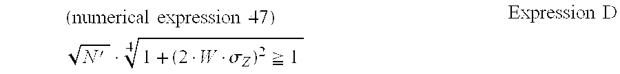
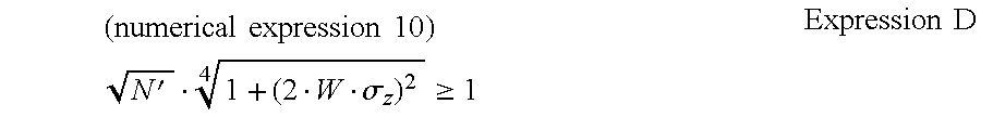
Moreover, according to another illuminating method of this invention (hereinafter referred to as a second illuminating method), in an optical system for forming an image of an object to be illuminated, after light axes of light beams emitted from N′ (N′ is an integer of 2 or more) light sources are aligned with each other, the coherence of the light beams is reduced, and the object to be illuminated is illuminated with the coherence of the light beams being reduced by this, when a light path length difference from one point on the object to be illuminated to an image corresponding thereto has a standard deviation σZ, the number N′ is set so that a relation expressed by the following expression D is satisfied: ( numerical expression 30 ) N · 1 + ( 2 · W · σ Z ) 2 1 4 Expression D
Figure US06249381-20010619-M00019
(in the expression D, “W” indicates a spectrum width of the wave number of the light beam emitted from the light source).
According to the second illuminating method, in the optical system for forming an image of an object to be illuminated, after light axes of light beams emitted from N′ light sources are aligned with each other, the coherence of the light beams is reduced, and the object to be illuminated is illuminated with the light beams of coherence reduced by this, and when the light path length difference from one point on the object to be illuminated to an image corresponding thereto has a standard deviation σZ, the number N′ is set so that a relation expressed by the following expression D is satisfied: ( numerical expression 31 ) N · 1 + ( 2 · W · σ Z ) 2 1 4 Expression D
Figure US06249381-20010619-M00020
Thus it is possible to reduce the speckle to a range (especially wherein the speckle contrast is 10% or less) which is sufficiently permissible for, for example, a human eye. By this, it is possible to use, as illuminating light, an optical beam in which the contrast of speckle is sufficiently reduced.
Moreover, as a device for carrying out the second illuminating method with good reproducibility, according to an illuminating device (hereinafter referred to as a second illuminating device) of this invention, in an optical system for forming an image of an object to be illuminated, after light axes of light beams emitted from N′ (N′ is an integer of 2 or more) light sources are aligned-with each other, the coherence of the light beams is reduced, and the object to be illuminated is illuminated with the light beams of coherence reduced by this, and when the light path length difference from one point on the object to be illuminated to an image corresponding thereto has a standard deviation σZ, the number N′ is set so that a relation expressed by the following expression D is satisfied: ( numerical expression 32 ) N · 1 + ( 2 · W · σ Z ) 2 1 4 Expression D
Figure US06249381-20010619-M00021
(in the expression D, “W” indicates a spectrum width of wave number of the light beam emitted from the light source).
BRIEF DESCRIPTION OF THE DRAWINGS
FIG. 1 is a graph showing the change of speckle contrast due to the surface roughness of an object.
FIG. 2 is a partial schematic view showing an illuminating device using a conventional fly eye lens.
FIG. 3 is a partial schematic structural view showing an illuminating device using a conventional prism.
FIG. 4 is a schematic view for explaining the necessity of speckle control.
FIG. 5 is another schematic view for explaining the necessity of speckle control.
FIG. 6 is a schematic view showing the principle of coherence reduction by mode dispersion in an optical fiber.
FIGS. 7A and 7B are schematic views showing a fiber bundle usable for the first embodiment.
FIG. 8 is a schematic structural view showing an illuminating device according to a first embodiment of this invention.
FIG. 9 is a schematic structural view showing the vicinity of a light source of an illuminating device according to a second embodiment.
FIG. 10 is a schematic structural view showing the vicinity of another light source of the illuminating device according to the second embodiment.
FIG. 11 is a schematic structural view showing the vicinity of a light source of an illuminating device according to a third embodiment.
FIG. 12 is a schematic structural view showing the vicinity of another light source of the illuminating device according to the second embodiment.
FIG. 13 is a schematic view showing the structure of the vicinity of a spatial modulator of an illuminating device according to a fourth embodiment.
FIG. 14 is a schematic view showing the structure of the vicinity of another spatial modulator of the illuminating device according to the fourth embodiment.
FIG. 15 is a schematic structural view showing a measuring device according to a fifth embodiment.
FIG. 16 is a schematic structural view showing an exposure device (or microscope) according to a sixth embodiment.
FIGS. 17A to 17C are schematic structural views showing a measuring device according to a seventh embodiment.
FIG. 18 is a schematic structural view showing an illuminating device according to an eighth embodiment.
FIG. 19 is a graph showing the change of contrast of speckle due to a laser light wavelength spectrum width.
FIG. 20 is a graph showing the number of lasers required to suppress the speckle contrast to 10% in the eighth embodiment of this invention.
FIG. 21 is a graph showing the number of lasers required to suppress the speckle contrast to 5% in the eighth embodiment
DETAILED DESCRIPTION OF THE PREFERRED EMBODIMENTS
First, the operation of the first illuminating method and the second illuminating method will be described.
In the present invention, for example, in an image display device, a measuring device, or a microscope, especially as light beams, when the center wavelength of the light beam emitted from N light sources having almost the same wavelength is λ0, the full width at half maximum of a wavelength spectrum is Δλ, the spectrum width of wave number is W, and the spectrum of the wave number is S(k), the following expression B and expression C are established. ( numerical expression 13 ) W = - π 2 · Δ k λ 0 2 Expression B S ( k ) = Exp [ - ( k - k 0 ) 2 2 · W 2 ] 2 π · W Expression C
Figure US06249381-20010619-M00022
Further, in an optical system in which light from each of the light sources is divided into M light beams, a light path length difference not less than a coherent distance is given to each of the light beams, and then, they are again combined (alternatively, the coherence of the light beam is reduced without dividing the light emitted from each of the light sources) to obtain light beams of reduced coherence, so that an object is illuminated with the light beams of reduced coherence to form an image of the object, when the light path length difference from one point on the object to a point on an image corresponding thereto has a fluctuation of standard deviation of σZ, the following relation is satisfied: ( numerical expression 34 ) NM · 1 + ( 2 · W · σ Z ) 2 1 4 Expression A
Figure US06249381-20010619-M00023
As the light source, it is desirable to use a semiconductor laser, a solid-state laser, harmonics thereof, and laser light after a nonlinear wavelength conversion process such as produces the sum of frequencies or difference of frequencies. As to the wavelength of laser light, laser light is not limited to only a visible range, but laser light in an ultraviolet range or infrared range may be used. Even in the case where the number of light sources is one (N=1) or in the case where wave division is not carried out (M=1), it is satisfactory if the foregoing expression A is satisfied. Especially as means forgiving the light path length difference, it is desirable to use an optical fiber.
That is, light from N light sources is divided into M light beams, and after a light path length difference not less than a coherent length is given to the light beams, if all light beams are combined, since each component is incoherent, the sum of intensity of N×M speckle patterns is observed. Thus, the speckle contrast becomes ( numerical expression 35 ) 1 NM
Figure US06249381-20010619-M00024
When the center wavelength of the light beams of the light source is λ0, the full width at half maximum of the wavelength spectrum is Δλ, the spectrum width of the wave number is W, and the spectrum of the wave number is S(k), that is, ( numerical expression 13 ) W = - π 2 · Δ k λ 0 2 S ( k ) = Exp [ - ( k - k 0 ) 2 2 · W 2 ] 2 π · W
Figure US06249381-20010619-M00025
and when the standard deviation of the speckle intensity to the mean value <I> of illumination intensity is σI, the speckle contrast is expressed by ( numerical expression 34 ) σ I I = 1 1 + ( 2 · W · σ Z ) 2 4
Figure US06249381-20010619-M00026
If the wavelength width of the laser light emitted from the light source is widened, the speckle contrast is reduced. When the speckle contrast of an imaging system is CI, the speckle contrast C of all systems is finally given by the following expression. ( numerical expression 38 ) C = C I NM · 1 + ( 2 · W · σ Z ) 2 4
Figure US06249381-20010619-M00027
When this light beam is used as illuminating light, image deterioration by speckle can be avoided, and it is possible to realize a display, a measuring device, an exposure device, and the like. However, at this time, especially like the case of the laser display, from the viewpoint of visibility of a human eye, it becomes an object that the speckle contrast C is 0.1 or less. If the contrast CI is 0.1 or less, it is not necessary to bother to reduce the speckle. Thus, it is assumed that the contrast CI is typically 0.1 or more (CI≧0.1).
Besides, it is desirable that the contrast of the finally observed speckle is 0.1 or less (C≦0.1). Thus, on the basis of the previous expression, the following expression A is established. ( numerical expression 34 ) NM · 1 + ( 2 · W · σ Z ) 2 1 4 Expression A
Figure US06249381-20010619-M00028
This is a condition where the contrast of speckle becomes 10% or less, which is a permissible degree when a person observes an image.
Especially in the case where a demand for the contrast of speckle is severe, such as in a still picture, it is desirable that the contrast C is 5% or less. In this case, it is satisfactory if the following equation is satisfied. ( numerical expression 40 ) NM · 1 + ( 2 · W · σ Z ) 2 2 4 Expression A
Figure US06249381-20010619-M00029
Although the permissible range of the speckle contrast is changed when the field of application becomes different, it is conceivable that the speckle contrast (10% or less, further, 5% or less) required for a display device such as a laser display has the most severe value. If the contrast is within the foregoing range, the light can be sufficiently used for a measuring device, an exposure device, a microscope, or the like.
In the present invention, if the foregoing conditions are satisfied, it is satisfactory if the number of light sources and the number of divisions (number of divided waves) is 1 or more. That is, in the first illuminating method and illuminating device of this invention, such a case is considered that the number N of light sources is 1 or more, and the number M of divided beams is 2 or more. Besides, in the second illuminating method and illuminating device of this invention, such a case is intended that the number N of light sources is 2 or more, and the number M of divided beams is 1.
As the optical source, it is advantageous in view of application to use a semiconductor laser which can be easily handled, a solid-state laser, and wavelength conversion light due to the nonlinear optical effect. Particularly, since the semiconductor laser has a wide oscillation wavelength width, the spectrum width W of the wave number is large. Thus, the number of lasers or the number of divided waves can be lessened, so that the optical system becomes simple.
It is also possible to use ultraviolet light by wavelength conversion of an excimer laser or solid-state laser as the optical source. Since the illuminating device using such short wavelength laser light has high resolution capability, it is especially suitable for an exposure device.
Further, as the means for giving a difference to the light path length, it is preferred to use a bundle of optical fibers with changed lengths. Other than that, means such as the foregoing prism (see FIG. 3) or fly eye lens (see FIG. 2) may be used.
Incidentally, it is naturally possible to apply the illuminating device of this invention to not only a display but also a microscope or a measuring device, and further to an exposure device or the like.
Next, the first illuminating method and the first illuminating device of this invention will be described in more detail.
In the first illuminating method and the first illuminating device of this invention, concerning the light beam emitted from the light source, when the center wavelength of the light beam is λ0, the full width at half maximum of the wavelength spectrum is Δλ, the spectrum width of the wave number is W, and the spectrum of the wave number is S(k), it is desirable that the following expressions B and C are satisfied. ( numerical expression 13 ) W = - π 2 · Δ k λ 0 2 Expression B S ( k ) = Exp [ - ( k - k 0 ) 2 2 · W 2 ] 2 π · W Expression C
Figure US06249381-20010619-M00030
Moreover, it is desirable that the number M and the number N are set so that the relation expressed by the following expression A′ is satisfied. ( numerical expression 40 ) NM · 1 + ( 2 · W · σ Z ) 2 2 4 Expression A
Figure US06249381-20010619-M00031
By making the setting in such a manner, it is possible to suppress the speckle contrast to 5% or less.
Besides, it is desirable that in order to give the light path length difference as the coherent distance or more to the light beams after division, the light beams emitted from the light source are made incident on an optical fiber group of a plurality of bundled optical fibers which have lengths different from each other by the coherent distance or more. It is desirable to use a multi-mode optical fiber for the optical fiber.
In general, in the coherent light beam transmitting through the multi-mode optical fiber, its coherence is reduced by mode dispersion. Further, since the lengths of the plurality of optical fibers are different from each other by a length not less than the coherent length, the optical beams emitted from the respective optical fibers do not have coherence with each other.
Thus, the size (spectrum) of the light source is regarded as widened, and spatial coherence is reduced. The coherence of light beams after combination is reduced, and when the coherence is reduced, the contrast of speckle is reduced. Further, when this light is used as illuminating light, a display, a measuring device, an exposure device, and the like can be realized without deterioration of an image by speckle. Further, since the intensity distribution of the emitted light beam from the multi-mode optical fiber is uniform, uniform and high intensity illumination can be realized at the same time as the reduction of coherence.
Hereinafter, mode dispersion in the multi-mode fiber will be described in detail.
In the case of a step index fiber composed of a core with a high refractive index and a clad with a lower refractive index, the total number N of confinement modes is given by the following expression (1).
N≡V2/2  expression (1)
Where, in the expression (1), V is a normalized frequency expressed by the following expression (2).
V=k 0 a(n 1 2 −n 2 2)½   expression (2)
In the expression (2), k0 is the wave number in vacuum (=ω/c: ω is the angular frequency, c is the light speed), n1 is a core refractive index, n2 is a clad refractive index, and “a” is a core diameter.
For example, when an optical beam of wavelength 500 nm is made incident on a plastic fiber with a core diameter “a” of 500 μm, a core refractive index n1=1.492, and a clad refractive index n2=1.456, the number N of total confinement modes becomes about 500,000. That is, in the multi-mode fiber, a pulse is greatly widened by mode dispersion. In the case of such a multi-mode fiber, it is conceivable that the mode refractive index extends from the core refractive index to the clad refractive index.
Thus, the distance between the top and the rear of a pulse passing through an optical fiber with a length L is expressed by the following expression (3).
c{(n 1 L/c)−(N 2 L/c)}=(n 1 −n 2)L  expression (3)
As a result, when a light beam (δ function-like pulse incident at the same time) of wavelength 500 nm incident on a light incident side of an optical fiber at the same time is emitted from, for example, the optical fiber with a length of 1 m, it is widened to a pulse width of 2.6 cm between the front and the rear.
Like this, when the coherence length of the light beam incident on the optical fiber is shorter than the pulse width, even if the incident light is continuous light, the coherence is reduced. For example, if laser light of a solid laser capable of oscillating at multi-mode, or its harmonics is used, a coherence length of about several mm can be realized. Thus, time coherence of the optical beam transmitting through the multi-mode optical fiber is reduced.
Besides, also in space, spatial coherence is reduced by superimposition of many modes. By this influence, as described above, even if the mode dispersion length (difference between the fastest mode and the slowest mode at the light emitting end of the optical fiber) of the optical fiber is shorter than the coherence length of the light source, the coherence is reduced. However, in order to suppress the coherence more effectively, it is desirable that the mode dispersion length of the optical fiber is longer than the coherence length of the optical source. For that purpose, it is satisfactory if the length L of the fiber is
L>(a/n 1 −n 2)
(where, “a”, n1 and n2 are the same as those described before).
When the coherence length of the optical beam transmitting through the multi-mode optical fiber is made “m”, if the difference between lengths of the plurality of bundled optical fibers is “m” or more, the optical beams emitted from the plurality of optical fibers do not have coherence with each other. Thus, when these are mixed (combined), the coherence of the light beams is reduced and the speckle becomes hard to produce. Thus, when the length of an optical fiber, the number of fibers, and the coherence length of a light source are suitably selected and designed, speckle can be sufficiently suppressed.
Here, it may be necessary to pay attention to a loss in light intensity during transmission. However, at present, in the case of a plastic fiber, its transmission loss is about 0.1 dB/m to a light beam of wavelength 500 nm to 550 nm and is minimum. That is, for the length of 1 m, 5 m, 10 m, and 50 m, an internal transmissivity becomes 97.7%, 89.1%, 79.4%, and 31.6%, respectively. Thus, the illuminating method of this invention attains a sufficiently permissible degree for application usage of the device (for example, a display device, a measuring device, a microscope, an exposure device, etc.).
Although the transmissivity of the hollow optical fiber for guiding ultraviolet rays is relatively low at present, it is expressed that sufficient transmission efficiency will be obtained in the future. Besides, it is conceivable that by improvement of output of various lasers themselves as well, sufficient emitted light can be obtained according to an application use.
Besides, in the first illuminating method and the first illuminating device of this invention, the light beam emitted from the light source is laser light in a visible light wavelength region, and it is possible to illuminate a film or a spatial modulator as an object to be illuminated. However, for example, it is also possible to use laser light in an ultraviolet light wavelength region and to apply this invention to an illuminating light source for an exposure device using the short wavelength laser light.
It is desirable that the light beam is laser light emitted from a semiconductor laser or laser light by nonlinear wavelength conversion of laser light emitted from a solid-state laser (for example, Nd: YAG, etc.). However, any other laser light source (or its harmonics), such as a gas laser or dye laser, may be suitably used.
Moreover, in the first illuminating method and the first illuminating device of this invention, the number of light sources is made one, and a light beam emitted from this light source can be divided into plural beams. That is, it is desirable to make N=1 and M≧2. Moreover, it is further desirable that the number of light sources is made plural, and a light beam emitted from each of these light sources is divided into plural beams. That is, it is further desirable to make N≧2 and M≧2.
Especially, in order to reduce the contrast of speckle to about 10%, it is desirable that M or N is made 100 or more. Incidentally, although the number M or N may be 100 or more, it is satisfactory if M×N is 100 or more. Further, in order to reduce the contrast of speckle to about 5%, it is desirable that M or N is made 400 or more. In this case as well, although each of M or N may be 400 or more, it is satisfactory if the number of M×N is 400 or more.
In the first illuminating method and the first illuminating device of this invention, it is desirable that a light beam of reduced coherence is used as an illuminating light beam for a display device, a measuring device, a microscope, or an exposure device. That is, a light beam of reduced coherence can be used for various illumination uses.
Next, the second illuminating method and the second illuminating device of this invention will be descried in detail.
In the second illuminating method and the second illuminating device of this invention, concerning a light beam emitted from a light source, when the center wavelength of the light beam is λ0, the full width at half maximum of a wavelength spectrum is Δλ, the spectrum width of wave number is W, and the spectrum of the wave number is S(k), it is desirable that the following expressions B and C are established. ( numerical expression 13 ) W = - π 2 · Δ k λ 0 2 Expression B S ( k ) = Exp [ - ( k - k 0 ) 2 2 · W 2 ] 2 π · W Expression C
Figure US06249381-20010619-M00032
Moreover, it is desirable that the number N′ is set so that the relation expressed by the following expression D′ is satisfied. ( numerical expression 44 ) N · 1 + ( 2 · W · σ Z ) 2 2 _ 4 Expression D
Figure US06249381-20010619-M00033
By making the setting in such a manner, it is possible to suppress the contrast of speckle to 5% or less.
Besides, it is desirable to make an optical beam, which is emitted from the light source, of laser light in a visible light wavelength range, and to illuminate a film or a spatial demodulator as an object to be illuminated. However, it is also possible to use, for example, laser light in an ultraviolet light wavelength range, and to use it as an illuminating light source of an exposure device using short wavelength laser light.
Besides, it is desirable that the light beam is laser light emitted from a semiconductor laser or laser light by nonlinear wavelength conversion of laser light emitted from a solid-state laser. However, any other laser light source, such as gas laser or a dye laser, may be suitably used.
From the viewpoint that the contrast of speckle is suppressed to 10% or less, it is desirable that N′ is made 100 or more. From the viewpoint that the contrast of speckle is suppressed to 5% or less, it is desirable that N′ is made 400 or more.
Further, in the second illuminating method and the second illuminating device of this invention, it is desirable that a light beam of reduced coherence is used as an illuminating light beam for a display device, a measuring device, a microscope, or an exposure device. That is, as a light beam of reduced coherence, it can be used for various illumination uses.
In the following, preferred embodiments of this invention will be described.
First embodiment (case where a fiber bundle is used):
First, description will be made on a case where a plurality of optical fibers with different lengths are used, and a light path length difference is given to laser light emitted from one light source (N=1, M≧2).
As shown in FIG. 7A, all of the incident ends (incident side fiber bundle portion) 3 and the emitting ends (emitting side fiber bundle portion) 4 of a plurality of multi-mode optical fibers 2 a, 2 b, 2 c, 2 d . . . having lengths different from each other by a coherence length or more of a light beam incident on each of the optical fibers are arranged, and these are bundled, so that a fiber bundle 1 composed of the optical fiber group is constructed.
It is desirable that the way of bundling especially the incident side fiber bundle portion 3 and the emitting side fiber bundle portion 4 is made, as shown in FIG. 7B, as close as possible in view of coupling efficiency of emitted (or incident) laser light. When symmetry is taken into consideration, it is most advantageous to take an arrangement forming an equilateral hexagon, or a hexagonal close-packed structure in crystal structure.
Each of the multi-mode optical fibers 2 has a double structure made of a core 5 with a large refractive index and a clad 6 with a relatively small refractive index, and the lengths of the fibers in the fiber bundle 1 are different from each other. It is satisfactory if the difference of lengths is not less than the coherence length of coherent light incident on the fiber bundle 1, and the difference of the lengths of at least two optical fibers is not less than the coherence length. However, it is desirable that the lengths of all the bundled optical fibers are different from each other by not less than the coherence length.
As a method of bundling a plurality of optical fibers with different lengths, as shown in FIG. 7A, some of the respective fibers may be folded in a curved state so that they become longer than the other fibers by a length not less than the coherence length. Even if this folded portion 8 is provided, the light incident portion and light emitting portion of the fiber bundle 1 are common or are located at the same position to the respective fibers. When the optical fibers are used like this, the surrounding space is effectively used by folding or the like so that the foregoing difference in length can be easily and compactly realized. The shape of a fiber is not limited to that shown in FIG. 7A, but can be formed into an arbitrary shape by using the size of a curvature of an optical fiber.
Thus, in the fiber bundle 1 shown in FIG. 7A, coherent laser light α incident on the incident side fiber bundle portion 3 at which the plurality of optical fibers are bundled is divided through the fiber bundle 1, and is emitted from the emitting end 4 as optical beams of reduced coherence, ideally, as incoherent light beams.
That is, the laser light a incident on the incident side fiber bundle portion 3 is incident on each of the multi-mode optical fibers 2 a, 2 b, 2 c, 2 d . . . while having the same or substantially the same intensity, and is emitted as laser light beams (a), (b), (c), (d) . . . in which time coherence and spatial coherence are reduced by mode dispersion in each of the multi-mode optical fibers.
Since the lengths of the multi-mode optical fibers are different from each other by not less than the coherence length, the laser light beams (a), (b), (c), (d) . . . emitted from the emitting side fiber bundle portion 4 of the respective multi-mode optical fibers have phase differences each corresponding to a difference of length not less than the coherence length. The laser light beams emitted from the respective optical fibers are not coherent to each other, and a combination of these laser light beams produces a light beam which has high intensity and is excellent in directionality, and at the same time, has reduced coherence and is substantially incoherent.
Thus, the coherent laser light is transmitted through the bundle fiber with the foregoing simple structure, and is converted into a substantially incoherent light beam, and especially, can be used as illuminating light for a display, a measuring device, a microscope, an exposure device, or the like. Since the coherence is reduced through the optical fiber (fiber bundle), the coherence reduction effect is sufficient, the intensity distribution is uniform, and the optical loss is low.
Next, a display device (laser display) using the fiber bundle shown in FIGS. 7A and 7B will be shown in FIG. 8.
In the display device shown in FIG. 8, first, laser light emitted from a laser resonator 10 is incident on a lens 11. Next, the laser light condensed by the lens 11 is incident on an incident side fiber bundle portion of a bundle fiber 12 similar to the above.
The laser light emitted through the bundle fiber 12 and an optical fiber 13 illuminates, for example, a spatial modulator (transmission type light valve) made of a transmission type liquid crystal display element through a lens 14. Incidentally, the optical fiber 13 may be the fiber bundle 12 or may be another optical fiber coupled with the fiber bundle 12.
By illuminating light of high intensity from the lens 14, an image by the spatial modulator 15 is projected with high brightness, high fineness, and excellent contrast on a screen 17 through a projection lens 16.
Like this, the coherence of the illuminating light for illuminating the spatial modulator 15 is reduced by the effect described before, so that speckles are reduced on both the screen and the retina of an observer observing this.
Here, as the laser resonator 10, a solid-state laser, a semiconductor laser, a gas laser, a dye laser, or the like may be used, or harmonics of these (for example, second harmonic or fifth harmonic of Nd: YAG laser) may be used. In order to obtain light of three primary colors, a light source such as an LED or a lamp other than the laser can also be used in addition to the laser. Further, it is not necessary that the number of light sources is one, but a plurality of light sources may be used. By this, it becomes possible to use a semiconductor laser which has a low output, but has high efficiency and is easily handled. In that case, when the plurality of laser light beams are combined, a fiber bundle as shown in FIGS. 7A and 7B may be used.
(Second embodiment)
For the purpose of obtaining illuminating light of three primary colors used for a display device or the like, this embodiment shows the structure of a light source portion of illuminating light beams, which uses a semiconductor laser capable of oscillating laser light in a red wavelength region, a semiconductor laser capable of oscillating laser light in a green wavelength region, and a semiconductor laser capable of oscillating laser light in a blue wavelength region.
That is, as shown in FIG. 9, laser light emitted from each of a semiconductor laser 21 a for red (R) oscillation, a semiconductor laser 21 b for green (G) oscillation, and a semiconductor laser 21 c for blue (B) oscillation is guided through lenses 22 a, 22 b, and 22 c to fiber bundles 23 a, 23 b, and 23 c according to the present invention, and the laser light of each color can be coupled through the fiber bundles (N=1, M≧2).
Like this, for the purpose of obtaining the three primary colors, the semiconductor lasers of red, green, and blue oscillation are used, and the emitted light beam from each of the semiconductor lasers is guided through the fiber bundle. As a result, the light beam can be used as illuminating light in which its coherence is reduced and at the same time, the directionality is high and the intensity is high.
FIG. 10 shows an illuminating device which is based on this embodiment and has an object to obtain illuminating light with higher intensity and reduced coherence (N=3, M≧2).
As shown in FIG. 10, red laser light beams from red semiconductor lasers 25 a, 25 b and 25 c are guided through lenses 22 to fiber bundles 26 a, 26 b, and 26 c, respectively, and these fiber bundles are further coupled, so that red laser light with higher intensity can be transmitted through a fiber bundle 27 a. It is needless to say that green laser light and blue laser light can be transmitted in the same way.
The fiber 27 a for transmitting the red laser light, a fiber 27 b for transmitting the green laser light, and a fiber 27 c for transmitting the blue laser light are further bundled, so that laser light of three primary colors with higher intensity can be transmitted through a fiber 28. Of course, the number of semiconductor lasers oscillating in each color is not limited to three, but any number of semiconductor lasers may be used. A fiber bundle with a folded portion is not limited to the positions of the fiber bundles 26 a, 26 b, and 26 c, but may be positioned at the fibers 27 a, 27 b, and 27 c or the fiber 28.
(Third embodiment)
This embodiment shows the structure of a light source portion of illuminating light beams using laser light beams of different polarized states.
FIG. 11 is a main portion schematic view showing the structure of a light source in which a laser coupler unit 31 composed of a semiconductor laser 32 a for oscillating P-polarized light, a semiconductor laser 32 b for oscillating S-polarized light, lenses 33 a and 33 b, a mirror 34, and a polarization beam splitter 35, and a lens 36 are used to combine the laser light of the P-polarized light and the laser light of the S-polarized light in a fiber bundle 37. When the polarized beam splitter is used like this, laser light with high intensity can be effectively guided (N=2, M≧2).
FIG. 12 shows an illuminating device using laser light beams with different polarized states, which is basically similar to FIG. 11. Red laser light beams emitted from a laser coupler unit 31 a capable of oscillating red (R) laser light are combined in a fiber bundle 37 a through a lens 36 a. Similarly, green laser light beams emitted from a laser coupler unit 31 b capable of oscillating green (G) laser light, and blue laser light beams emitted from a laser coupler unit 31 c capable of oscillating blue (B) laser light are made incident on fiber bundles 37 b and 37 c through lenses 36 b and 36 c, respectively. Then, the respective bundle fibers are bundled (N 2, M≧2).
Incidentally, in the second embodiment and the third embodiment shown in FIGS. 9 to 12, there are shown examples in which emitted light beams from the semiconductor lasers having different oscillation wavelength ranges are guided to one fiber bundle. However, other than this, it is possible to consider some methods to provide light of three primary colors.
A first method is modulation of a light source. That is, laser light of each color is periodically oscillated, and spatial color separation (modulation) is carried out by a spatial modulator at every period, so that a color image is obtained.
A second method is spatial modulation using a color filter. That is, if each color spatial-modulator includes, for every pixel, a filter to allow only a specific color to pass, a color image by the spatial modulator can be obtained by this. The combination of three primary colors can also be carried out at a portion of a spatial modulator as described in the following fourth embodiment.
(Fourth embodiment)
This embodiment is a structural example in which, for example, a reflection type spatial modulator such as a reflection type liquid crystal display element is used, and after three primary colors are combined at this portion of the spatial modulator, light is guided to, although not shown, a fiber bundle as shown in FIGS. 7A and 7B.
As shown in FIG. 13, by using the foregoing method, when the illuminating light is made incident on a unit 42 composed of a reflection type spatial modulator 40 and a beam splitter 41 through a not-shown fiber bundle, three primary colors can be modulated by one spatial modulator (unit). Here, if the beam splitter 41 is replaced by a polarization beam splitter and a wavelength plate is disposed in the spatial modulator itself or on its light path, the modulation efficiency can be increased (N 1, M≧2).
FIG. 14 shows an example in which the unit shown in FIG. 13 is used for each color, that is, illuminating light beams are guided through not-shown fiber bundles to a red spatial modulator unit 42 a, a green spatial modulator unit 42 b, and a blue spatial modulator unit 42 c, and after they are subjected to space modulation, they are combined by using a dichroic mirror 43 (N=1, M≧2).
Although this embodiment states the reflection type spatial modulator (reflection type light valve), a transmission type spatial modulator (for example, a transmission type liquid crystal display element) can be constructed in the same manner. As the reflection type spatial modulator, a digital micro mirror or the like may be used.
In the foregoing first embodiment to the fourth embodiment, the illuminating methods and the illuminating devices for mainly a displaying device (display) have been described. However, this invention is not limited to these embodiments, but various applications can be devised.
Next, description will be made on an example in which a light beam is divided in accordance with this invention, and the illuminating light from a fiber bundle is given a light path length difference of not less than the coherence length to light beams after division to produce a light source for a measuring device or a microscope.
Although not shown, when a hollow multi-mode optical fiber is used as the multi-mode bundle fiber, the application to laser light in an ultraviolet range can also be made. When this is used, it is possible to realize, for example, an ultraviolet ray exposure device in a manufacturing process of a semiconductor or the like. These can be easily realized by replacing the foregoing spatial modulator and the screen by, for example, a sample (object to be observed) and a human retina (or CCD etc.) in the case of a microscope, an object to be measured and an image input device in the case of a measuring device, and a mask and an exposed material in the case of an exposure device.
(Fifth embodiment)
This embodiment is an example in which this invention is applied to a measuring device.
That is, as shown in FIG. 15, illuminating light “a” emitted from a fiber bundle 45 and having reduced coherence is projected on a measured object 46 having a surface 47 to be measured. When light beam “b” reflected by the surface 47 to be measured is detected by a light receiving unit 49 through an observation optical system 48, the properties of its surface (surface roughness, etc.), for example, can be measured.
Here, if there is a feature in spectral characteristics, such as transmissivity or reflectivity of the object to be measured, it is effective to use light of a wavelength suitable for that. For example, in a selecting apparatus or the like in an FA (Factory Automation), for the purpose of recognizing an object having a specific color, when laser light having a specific wavelength is applied, reflectivity to objects with other colors becomes different, so that its recognition becomes easy. In a solder tester, illuminating light in a green wavelength range is most effective from the viewpoint of reflectivity of a substrate. This can be realized by using a semiconductor laser in the green wavelength region. Further, by the method of this invention, the accuracy in examination is further improved.
That is, in the examining step, since speckle becomes a cause for noise if the coherence is reduced in accordance with this invention, the accuracy can be improved. When a specific wavelength filter is added to the observation optical system 48, it becomes possible to further improve the accuracy without receiving influence from disturbance light.
Here, it is also possible to consider observation with not only the reflected light of illuminating light, but also transmitting light or fluorescent light of the illuminating light. In this case as well, reducing the speckle of the illuminating light results in suppression of noise.
(Sixth embodiment)
This embodiment is an example in which a fiber bundle of this invention is used for an optical unit such as an exposure device or a microscope.
That is, as shown in FIG. 16, an emitted light beam from a fiber bundle 51 is applied to an object 53 to be illuminated through a condenser lens 52 in Kohler's illumination or critical illumination, and an image 55 of the illuminated object 53 is formed by using an object lens 54. Here, if the surface of the image is observed, a microscope is obtained. If a resist, a film, or the like is exposed (or recorded) with the image of the object 53 to be illuminated, an exposure device is obtained. Incidentally, as shown by an arrow in the drawing, the object lens 54 can be suitably moved.
Here, similarly to the foregoing fifth embodiment, if there is a feature in the spectral characteristics such as transmissivity or reflectivity of the object to be illuminated, it is effective to use light of a wavelength suitable for that. For example, if a resist or film as an exposure material has high sensitivity for a specific wavelength, it is effective to make exposure by that wavelength. This becomes possible, if a laser having a specific oscillation wavelength range and a narrow wavelength width is used. When the laser light is made to have reduced coherence by the method of this invention and the speckle is removed, an exposure process superior in contrast can be realized.
As an example, it is effective to use a light beam in a green wavelength region for recording of a digital audio track to a movie film, and if the method of this invention is used, this can be easily realized. As another example, it is possible to consider an exposure device in which a hollow waveguide is replaced by a fiber, and ultraviolet laser light of an excimer laser, harmonics of a solid-state laser, or the like is used. Since this not only suppresses the speckle, but also unifies the illumination distribution, the device becomes inexpensive, simple, and superior in performance.
In the case where a microscope is constructed, it is possible to realize a microscope that uses a single wavelength and has no speckle. Thus, it is possible to construct a spectral or fluorescent microscope by using characteristics of reflectivity or transmissivity of a sample. It is possible to consider wide application of this microscope, such as not only application for medicine or a living body, but also a process check of a semiconductor.
Further, in this embodiment as well, it is also possible to consider the use of not only reflected light of illumination, but also transmitting light or fluorescent light. In this case as well, to reduce the speckle of illuminating light results in suppression of noise.
(Seventh embodiment)
This embodiment is an example of a measuring device using the illuminating method of this invention.
As an example of a measuring device other than the measuring device shown in the sixth embodiment, it is possible to consider the use of an interferometer such as a low coherent interferometer which has attracted attention in recent years. FIG. 17(A) shows an example of its structure.
That is, a light beam from a fiber bundle 60 is made parallel light by a collimator lens 61 and its wave front is divided by a beam splitter 62. One light beam (transmitting light) advances toward a reference mirror 63 (distance from the beam splitter is L) and the other light beam (reflected light) advances toward a test piece side.
Here, in the case where the coherence length of emitted light of a multi-mode fiber bundle is “a” or less, when a mirror at the test piece side is mirror 64 b located at a position remote from the beam splitter by a distance L−a, or is a mirror 64 c located at a position remote from the beam splitter by a distance L+a, interference stripes are hardly produced. On the other hand, like mirror 64 a, only when a mirror is located at a position remote from the beam splitter by a distance L, interference stripes (speckle patterns) are produced.
Here, instead of the mirrors 64 a, 64 b, and 64 c, when a sample 66 having a three-dimensional shape as shown in FIG. 17(B) or a living body sample 67 as shown in FIG. 17(C) is placed and reflected light from this is observed as interference light, it is possible to observe the three-dimensional shape of the sample in a state where the sample is cut into round slices. When the contrast of the interference stripes is measured, this device can also be used as a length measuring device.
If the coherence length is designed based on the length of the multi-mode fiber bundle and the like, it is also possible to apply the device to various-uses. In this case as well, to suppress the speckle by reduction of coherence results in extreme decrease of noise at the time of observation or measurement, so that an improvement in accuracy and performance can be expected.
(Eighth embodiment)
Next, an example in which the number of light sources is one, will be described with reference to FIG. 18 (M=1, N≧2).
According to this embodiment, laser light oscillated from a light source 101 composed of semiconductor lasers arranged on a plane, a semiconductor array, or vertical resonator surface emitting lasers (VCSEL) is made pseudo-parallel light through lenses arranged on a plane or micro lens array 102, and this is condensed by one lens 103 to a multi-mode optical fiber 104. Light made uniform by the multi-mode optical fiber 104 is projected through a lens 105 on a screen 106 as an object to be illuminated.
In this case, since the number of divisions is one (M=1, that is, division is not made), it is desirable to use a number of light sources (that is, sufficiently large N) in order to sufficiently reduce the contrast of speckle to a wavelength width W of each laser.
Here, in the case where the standard deviation of fluctuation of light path length (that is, twice the standard deviation of screen roughness) σZ is 1 μm, 10 μm, and 100 μm, and the wavelength λ is 650 nm, 550 nm, and 450 nm, the manner of change of the speckle produced by one light source with respect to the change of wavelength width is shown in FIG. 19.
In the case where the standard deviation σZ of fluctuation of light path length and the wavelength λ of laser light are constant, it is understood from FIG. 19 that there is a tendency that as the wavelength width Δλ of laser light becomes large, the contrast of speckle is lowered. Moreover, it is understood that in the case where the standard deviation σZ of fluctuation of light path length is constant, there is a tendency that as the wavelength of laser light becomes short, the contrast of speckle is apt to be lowered, and in the case where the wavelength of laser light is constant, as the standard deviation σZ of fluctuation of light path length becomes large, the contrast of speckle is lowered.
Concerning the same cases, results obtained after considering the number of laser light sources required to lower the contrast of speckle by 10% and 5% is shown in FIG. 20 and FIG. 21.
That is, as typical values, in the case where the standard deviation of roughness of a screen is of the order of about 10 μm, and a semiconductor laser with a full width at half maximum of about several nm is used, it is understood from FIG. 20 that when the number of light sources is made about 100, the contrast of speckle of a light beam in a visible wavelength range can be lowered to 10% (this is a range permissible for a human eye). Further, it is understood from FIG. 21 that when the number of light sources is made about 400, the contrast of speckle can be lowered to 5%.
As described above, according to the embodiment, coherent control which is easy, is inexpensive, and has high performance is carried out for various kinds of lasers, and this invention can be applied to a light source with suppressed speckle and for illuminating an object. Further, when the multi-mode fiber is used as the optical fiber, by superimposition of spatial modes, it is possible to unify the intensity of illumination, and at the same time, it is possible to reduce the coherence simply, at low cost, and with saved space (that is, without receiving a restriction in space). Further, a display, a measuring device, a microscope, an exposure device, or the like can be constructed by using a semiconductor laser and the like having high photoelectric conversion efficiency. By this, it is possible to attain an improvement of performance, miniaturization, and reduction of cost of the device.
Although this invention has been described with reference to the preferred embodiments, this invention is not limited to these embodiments.
For example, it is desirable that the incident position of light (coherent light) in the optical fiber group (or fiber bundle) used in the first embodiment and the like is the same or substantially the same among the respective optical fibers. Besides, it is desirable that the optical fiber group is bundled at the light incident position as close as possible.
When some of the plurality of optical fibers are folded, the lengths of the optical fibers are made different from each other by the coherence length or more of the coherent light. The way of folding is not particularly limited, but various shapes to satisfy the condition of length are selected. Particularly, it is desirable that the multi-mode optical fiber is a plastic optical fiber in view of a high transmissivity, large radius of curvature, and the like.
Alternatively, a hollow multi-mode optical fiber is used as the optical fiber, and the coherent light may be made laser light in an ultraviolet range (that is, a laser for emitting laser light in the ultraviolet range may be used as the light source). By this, it is possible to realize an optical device (especially an exposure device, etc.) with a light beam in the ultraviolet range as a light source.
In the illuminating method and the illuminating device of this invention, the illuminating light is used to illuminate a spatial modulator made of a liquid crystal element, a micro mirror, or the like, and its image is projected on the screen, so that the speckle is suppressed and a displaying device (display) with high brightness and high fineness can be realized. Further, an object to be measured is illuminated by using this illuminating light, and measurement is carried out as to the shape of the object, the intensity of reflected and/or transmitted light, and the like, so that a measuring device with high measuring accuracy can be realized. Moreover, a microscope using this illuminating light, such as a fluorescent microscope, can be realized. Further, when this illuminating light (especially a laser in the ultraviolet range) is used as a light source and an object to be exposed is illuminated through a mask or the like, an exposure image with high contrast and deep focal depth can be obtained (especially an ultraviolet ray exposure device).
As described above, according to the first illuminating method of the present invention, in an optical system for forming an image of an object to be illuminated, a light beam emitted from N (N is an integer not less than 1) light sources is divided into M light beams (M is an integer not less than 2), a light path length difference of not less than a coherent distance is given to the light beams after division, and then, light axes of these light beams are again aligned with each other to illuminate the object with the light beams of coherence reduced by this, and when the light path length difference from one point on the object to be illuminated to an image corresponding thereto has a standard deviation cr., the number M and the number N are set so that the relation expressed by the following expression A is satisfied: ( numerical expression 34 ) NM · 1 + ( 2 · W · σ Z ) 2 1 4 Expression A
Figure US06249381-20010619-M00034
(in the expression A, “W” indicates a spectrum width of the wave number of the light beam emitted from the light source). Thus, for example, it is possible to reduce the speckle to a range (especially speckle contrast of 10%) sufficiently permissible for a human eye, and the light beam in which the contrast of speckle is sufficiently reduced can be used as illuminating light.
According to the first illuminating device of this invention, in an optical system for forming an image of an object to be illuminated, a light beam emitted from N (N is an integer not less than 1) light sources is divided into M divided light beams (M is an integer not less than 2), a light path length difference of not less than a coherent distance is given to the light beams after division, and then, light axes of these light beams are again aligned with each other to illuminate the object with the light beam of coherence reduced by this, and when the light path length difference from one point on the object to be illuminated to an image corresponding thereto has a standard deviation σZ, the number M and the number N are set so that the relation expressed by the following expression A is satisfied: ( numerical expression 34 ) NM · 1 + ( 2 · W · σ Z ) 2 1 4 Expression A
Figure US06249381-20010619-M00035
(in the expression A, “W” indicates a spectrum width of the wave number of the light beam emitted from the light source). Thus, the first illuminating method of this invention can be carried out with good reproducibility.
According to the second illuminating method of this invention, in an optical system for forming an image of an object to be illuminated, after light axes of light beams emitted from N′ (N′ is an integer of 2 or more) light sources are aligned with each other, the coherence of the light beams is reduced, and the object to be illuminated is illuminated with the light beams of coherence reduced by this, and when a light path length difference from one point on the object to be illuminated to an image corresponding thereto has a standard deviation σZ, the number N′ is set so that the relation expressed by the following expression D is satisfied: ( numerical expression 47 ) N · 1 + ( 2 · W · σ Z ) 2 1 4 Expression D
Figure US06249381-20010619-M00036
(in the expression D, “W” indicates a spectrum width of the wave number of the light beam emitted from the light source). Thus, for example, it is possible to reduce the speckle to a range (especially speckle contrast of 10%) sufficiently permissible for a human eye, and the light beam in which the contrast of speckle is sufficiently reduced can be used as illuminating light.
According to the second illuminating device of this invention, in an optical system for forming an image of an object to be illuminated, after light axes of light beams emitted from N′ (N′ is an integer of 2 or more) light sources are aligned with each other, the coherence of the light beams is reduced, and the object to be illuminated is illuminated with the light beams of coherence reduced by this, and when the light path length difference from one point on the object to be illuminated to an image corresponding thereto has a standard deviation σZ, the number N′ is set so that the relation expressed by the following expression D is satisfied: ( numerical expression 47 ) N · 1 + ( 2 · W · σ Z ) 2 1 4 Expression D
Figure US06249381-20010619-M00037
(in the expression D, “W” indicates a spectrum width of the wave number of the light beam emitted from the light source). Thus, the second illuminating method of this invention can be carried out with good reproducibility.

Claims (36)

What is claimed is:
1. An illuminating method using an optical system for forming an image of an object to be illuminated in which a light beam emitted from N (N is an integer not less than 1) light sources is divided into M light beams (M is an integer not less than 2), a light path length difference of not less than a coherent distance is given to the light beams after division, and then, light axes of these light beams are again aligned with each other to illuminate said object with the light beams of coherence reduced by this,
wherein when the light path length difference from one point on said object to be illuminated to an image corresponding thereto has a standard deviation σZ, the number M and the number N are set so that a relation expressed by the following expression A is satisfied: ( numerical expression 1 ) NM · 1 + ( 2 · W · σ z ) 2 4 1 Expression A
Figure US06249381-20010619-M00038
where, “W” indicates a spectrum width of wave number of the light beam emitted from said light source.
2. An illuminating method according to claim 1, wherein when a center wavelength of the light beam emitted from said light source is λ0, a full width at half maximum of a wavelength spectrum is Δλ, a spectrum width of wave number is W, and a spectrum of wave number is S(k), the following expressions B and C are established: ( numerical expression 2 ) W = π 2 · Δ k λ 0 2 Expression B S ( k ) = E χ p [ - ( k - k 0 ) 2 2 · W 2 ] 2 π · W . Expression C
Figure US06249381-20010619-M00039
3. An illuminating method according to claim 1, wherein the number M and the number N are set so that relation expressed by the following expression A′ is satisfied: ( numerical expression 3 ) NM · 1 + ( 2 · W · σ z ) 2 4 2. Expression A
Figure US06249381-20010619-M00040
4. An illuminating method according to claim 1, wherein in order to give the light path length difference of not less than the coherent distance to the light beams after division, the light beam emitted from said light source is incident on an optical fiber group in which a plurality of optical fibers with lengths different from each other by not less than the coherence length are bundled.
5. An illuminating method according to claim 4, wherein a multi-mode optical fiber is used as said optical fiber.
6. An illuminating method according to claim 1, wherein the light beam emitted from said light source is laser light in a visible light wavelength range, and illuminates a film or spatial modulator as said object to be illuminated.
7. An illuminating method according to claim 6, wherein the light beam is laser light emitted from a semiconductor laser, or laser light by nonlinear wavelength conversion of laser light emitted from a solid-state laser.
8. An illuminating method according to claim 1, wherein the number of light sources is made one, and the light beam emitted from said light source is divided into plural beams.
9. An illuminating method according to claim 1, wherein the number of light sources is made plural, and each of the light beams emitted from said light sources are divided into plural beams.
10. An illuminating method according to claim 1, wherein a number selected from the group of numbers consisting of the number M and the number N is 100 or more.
11. An illuminating method according to claim 1, wherein the light beam of reduced coherence is an illuminating light beam used for a device selected from the group of devices consisting of a display device, a measuring device, a microscope, and an exposure device.
12. An illuminating device comprising an optical system for forming an image of an object to be illuminated in which a light beam emitted from N (N is an integer not less than 1) light sources is divided into M divided light beams (M is an integer not less than 2), a light path length difference of not less than a coherent distance is given to the light beams after division, and then, light axes of these light beams are again aligned with each other to illuminate said object with the light beam of coherence reduced by this,
wherein when the light path length difference from one point on said object to be illuminated to an image corresponding thereto has a standard deviation σZ, the number M and the number N are set so that a relation expressed by the following expression A is satisfied: ( numerical expression 4 ) NM · 1 + ( 2 · W · σ z ) 2 4 1 Expression A
Figure US06249381-20010619-M00041
where, “W” indicates a spectrum width of wave number of the light beam emitted from said light source.
13. An illuminating device according to claim 12, wherein when a center wavelength of the light beam emitted from said light source is λO, a full width at half maximum of a wavelength spectrum is Δλ, a spectrum width of wave number is W, and a spectrum of the wave number is S(k), the following expressions B and C are established: ( numerical expression 5 ) W = π 2 · Δ k λ 0 2 Expression B S ( k ) = E χ p [ - ( k - k 0 ) 2 2 · W 2 ] 2 π · W . Expression C
Figure US06249381-20010619-M00042
14. An illuminating device according to claim 12, wherein the number M and the number N are set so that a relation expressed by the following expression A′ is satisfied: ( numerical expression 6 ) NM · 1 + ( 2 · W · σ z ) 2 4 2. Expression A
Figure US06249381-20010619-M00043
15. An illuminating device according to claim 12, wherein in order to give the light path length difference of not less than the coherent distance to the light beams after division, the light beam emitted from said light source is incident on an optical fiber group in which a plurality of optical fibers with lengths different from each other by not less than a coherence length are bundled.
16. An illuminating device according to claim 15, wherein a multi-mode optical fiber is used as said optical fiber.
17. An illuminating device according to claim 12, wherein the light beam emitted from said light source is made laser light in a visible light wavelength range, and illuminates a film or spatial modulator as said object to be illuminated.
18. An illuminating device according to claim 17, wherein the light beam is made laser light emitted from a semiconductor laser, or laser light by nonlinear wavelength conversion of laser light emitted from a solid-state laser.
19. An illuminating device according to claim 12, wherein the number of light sources is one, and the light beam emitted from said light source is divided into plural beams.
20. An illuminating device according to claim 12, wherein the number of light sources is plural, and each of the light beams emitted from said light sources is divided into plural beams.
21. An illuminating device according to claim 12, wherein a number selected from the group of numbers consisting of the number M and the number N is 100 or more.
22. An illuminating device according to claim 12, wherein the light beam of the reduced coherence is used as an illuminating light beam for a device selected from the group of devices consisting of a display device, a measuring device, a microscope, and an exposure device.
23. An illuminating method using an optical system for forming an image of an object to be illuminated in which after light axes of light beams emitted from N′ (N′ is an integer of 2 or more) light sources are aligned with each other, coherence of the light beams is reduced, and said object to be illuminated is illuminated with the light beams of coherence reduced by this,
wherein when a light path length difference from one point on said object to be illuminated to an image corresponding thereto has a standard deviation σZ, the number N′ is set so that a relation expressed by the following expression D is satisfied: ( numerical expression 7 ) N · 1 + ( 2 · W · σ z ) 2 4 2. Expression D
Figure US06249381-20010619-M00044
where, “W” indicates a spectrum width of wave number of the light beam emitted from said light source.
24. An illuminating method according to claim 23, wherein when a center wavelength of the light beam emitted from said light source is λO, a full width at half maximum of a wavelength spectrum is Δλ, a spectrum width of wave number is W, and a spectrum of the wave number is S(k), the following expressions B and C are established: ( numerical expression 8 ) W = π 2 · Δ k λ 0 2 Expression B S ( k ) = E χ p [ - ( k - k 0 ) 2 2 · W 2 ] 2 π · W . Expression C
Figure US06249381-20010619-M00045
25. An illuminating method according to claim 23, wherein the number N′ is set so that a relation expressed by the following expression D′ is satisfied: ( numerical expression 9 ) N · 1 + ( 2 · W · σ z ) 2 4 1. Expression D
Figure US06249381-20010619-M00046
26. An illuminating method according to claim 23, wherein the light beam emitted from said light source is laser light in a visible light wavelength range, and illuminates a film or spatial modulator as said object to be illuminated.
27. An illuminating method according to claim 26, wherein the light beam is laser light emitted from a semiconductor laser or laser light by nonlinear wavelength conversion of laser light emitted from a solid-state laser.
28. An illuminating method according to claim 23, wherein the number N′ is 100 or more.
29. An illuminating method according to claim 23, wherein the light beam of reduced coherence is made an illuminating light beam used for a device selected from the group of devices consisting of a display device, a measuring device, a microscope, and an exposure device.
30. An illuminating device comprising an optical system for forming an image of an object to be illuminated in which after light axes of light beams emitted from N′ (N′ is an integer of 2 or more) light sources are aligned with each other, coherence of the light beams is reduced, and said object to be illuminated is illuminated with the light beams of coherence reduced by this,
wherein when a light path length difference from one point on said object to be illuminated to an image corresponding thereto has a standard deviation σZ, the number N′ is set so that a relation expressed by the following expression D is satisfied: ( numerical expression 10 ) N · 1 + ( 2 · W · σ z ) 2 4 1 Expression D
Figure US06249381-20010619-M00047
where, “W” indicates a spectrum width of wave number of the light beam emitted from said light source.
31. An illuminating device according to claim 30, wherein when a center wavelength of the light beam emitted from said light source is λO, a full width at half maximum of wavelength spectrum is Δλ, a spectrum width of wave number is W, and a spectrum of the wave number is S(k), the following expressions B and C are established: ( numerical expression 11 ) W = π 2 · Δ k λ 0 2 Expression B S ( k ) = E χ p [ - ( k - k 0 ) 2 2 · W 2 ] 2 π · W . Expression C
Figure US06249381-20010619-M00048
32. An illuminating device according to claim 30, wherein the number N′ is set so that a relation expressed by the following expression D′ is satisfied: ( numerical expression 12 ) N · 1 + ( 2 · W · σ z ) 2 4 2. Expression D
Figure US06249381-20010619-M00049
33. An illuminating device according to claim 30, wherein the light beam emitted from said light source is laser light in a visible light wavelength region, and illuminates a film or spatial modulator as said object to be illuminated.
34. An illuminating device according to claim 30, wherein the light beam is laser light emitted from a semiconductor laser or laser light by nonlinear wavelength conversion of laser light emitted from a solid-state laser.
35. An illuminating device according to claim 30, wherein the number N′ is 100 or more.
36. An illuminating device according to claim 30, wherein the light beam of reduced coherence is an illuminating light beam used for a device selected from the group of devices consisting of a display device, a measuring device, a microscope, and an exposure device.
US09/298,273 1998-05-13 1999-04-23 Illuminating method and illuminating device Expired - Lifetime US6249381B1 (en)

Applications Claiming Priority (2)

Application Number Priority Date Filing Date Title
JP10130220A JPH11326826A (en) 1998-05-13 1998-05-13 Illuminating method and illuminator
JP10-130220 1998-05-13

Publications (1)

Publication Number Publication Date
US6249381B1 true US6249381B1 (en) 2001-06-19

Family

ID=15028967

Family Applications (1)

Application Number Title Priority Date Filing Date
US09/298,273 Expired - Lifetime US6249381B1 (en) 1998-05-13 1999-04-23 Illuminating method and illuminating device

Country Status (3)

Country Link
US (1) US6249381B1 (en)
JP (1) JPH11326826A (en)
KR (1) KR100592858B1 (en)

Cited By (127)

* Cited by examiner, † Cited by third party
Publication number Priority date Publication date Assignee Title
US6347173B1 (en) * 1998-05-15 2002-02-12 Sony Corporation Optical coherence reduction method and its device, illuminating method and its system and optical fiber bundle
GB2368743A (en) * 2000-08-28 2002-05-08 Leica Microsystems Method for reducing interference by decreasing laser coherence in a confocal scanning microscope.
US20020198457A1 (en) * 2001-04-30 2002-12-26 Tearney Guillermo J. Method and apparatus for improving image clarity and sensitivity in optical coherence tomography using dynamic feedback to control focal properties and coherence gating
US20030035215A1 (en) * 2001-08-15 2003-02-20 Silicon Light Machines Blazed grating light valve
US20030086145A1 (en) * 2001-11-08 2003-05-08 Desimone Andrew Frank Spatial light modulator apparatus
US6621636B2 (en) * 2000-12-26 2003-09-16 Semiconductor Energy Laboratory Co., Ltd. Laser irradiation apparatus and method of laser irradiation
WO2004031741A2 (en) * 2002-09-30 2004-04-15 Applied Materials Israel, Ltd. Illumination system for optical inspection
US6737635B2 (en) * 2000-04-04 2004-05-18 Leica Microsystems Heidelberg Gmbh Apparatus for combining light and confocal scanning microscope
US6747781B2 (en) 2001-06-25 2004-06-08 Silicon Light Machines, Inc. Method, apparatus, and diffuser for reducing laser speckle
US6764875B2 (en) 1998-07-29 2004-07-20 Silicon Light Machines Method of and apparatus for sealing an hermetic lid to a semiconductor die
US6767751B2 (en) 2002-05-28 2004-07-27 Silicon Light Machines, Inc. Integrated driver process flow
US6788901B2 (en) * 2001-04-25 2004-09-07 Meklyn Enterprises Limited Method of forming optical radiation beams for free-space optical communication systems
EP1463337A2 (en) * 2003-03-24 2004-09-29 Eastman Kodak Company Electronic imaging system using organic laser array illuminating an area light valve
US6800238B1 (en) 2002-01-15 2004-10-05 Silicon Light Machines, Inc. Method for domain patterning in low coercive field ferroelectrics
US6813059B2 (en) 2002-06-28 2004-11-02 Silicon Light Machines, Inc. Reduced formation of asperities in contact micro-structures
WO2004102258A2 (en) * 2003-05-15 2004-11-25 Stockeryale Canada Inc. Static method for laser speckle reduction and apparatus for reducing speckle
US6829258B1 (en) 2002-06-26 2004-12-07 Silicon Light Machines, Inc. Rapidly tunable external cavity laser
US6829077B1 (en) 2003-02-28 2004-12-07 Silicon Light Machines, Inc. Diffractive light modulator with dynamically rotatable diffraction plane
US20040257664A1 (en) * 2002-07-11 2004-12-23 Shigeki Hashimoto LIuminating optical device in image display device and image display device
US6839479B2 (en) 2002-05-29 2005-01-04 Silicon Light Machines Corporation Optical switch
US6850673B2 (en) 2002-03-07 2005-02-01 Johnston, Ii Richard Fendall Light source for fiber optics
US20050047172A1 (en) * 2003-08-28 2005-03-03 Ulrich Sander Light-emitting diode illumination system for an optical observation device, in particular a stereomicroscope or stereo surgical microscope
US20050128473A1 (en) * 1999-11-17 2005-06-16 Applied Materials, Inc. Method and apparatus for article inspection including speckle reduction
US6956878B1 (en) * 2000-02-07 2005-10-18 Silicon Light Machines Corporation Method and apparatus for reducing laser speckle using polarization averaging
US20050233512A1 (en) * 2000-12-26 2005-10-20 Semiconductor Energy Laboratory Co., Ltd. Method of manufacturing a semiconductor device
US7046420B1 (en) 2003-02-28 2006-05-16 Silicon Light Machines Corporation MEM micro-structures and methods of making the same
US20060126184A1 (en) * 2004-12-15 2006-06-15 Sung-Ha Kim Illumination system to eliminate laser speckle and projection system employing the same
US20060159391A1 (en) * 2003-09-26 2006-07-20 Miller Lee D Optical imagins system with optical delay lines
US20070070302A1 (en) * 2005-09-29 2007-03-29 Govorkov Sergei V Speckle reduction in laser illuminated projection displays having a one-dimensional spatial light modulator
US20070150779A1 (en) * 2005-12-09 2007-06-28 Asml Netherlands B.V. Lithographic apparatus and device manufacturing method
US20070178631A1 (en) * 2006-02-02 2007-08-02 Semiconductor Energy Laboratory Co., Ltd. Crystallization method for semiconductor film, manufacturing method for semiconductor device, and laser irradiation apparatus
US20080013097A1 (en) * 2006-06-23 2008-01-17 Asml Holding N.V. Resonant scanning mirror
US20080100837A1 (en) * 2002-01-24 2008-05-01 The General Hospital Corporation Apparatus and method for ranging and noise reduction of low coherence interferometry lci and optical coherence tomography oct signals by parallel detection of spectral bands
US20080128509A1 (en) * 2000-11-24 2008-06-05 Knowles C Harry Digital image capturing and processing system for automatically recognizing objects in a POS environment
US7397552B2 (en) 2004-09-27 2008-07-08 Applied Materials, Israel, Ltd. Optical inspection with alternating configurations
US20080212639A1 (en) * 2005-05-31 2008-09-04 Koninklijke Philips Electronics, N.V. Broadband Laser Lamp with Reduced Speckle
WO2009005808A1 (en) * 2007-07-03 2009-01-08 Ioannis Kymissis Software-controlled maskless optical lithography using fluorescence feedback
US20090023609A1 (en) * 2005-12-08 2009-01-22 Moon Youn Jung Programmable mask for fabricating biomolecule array or polymer array, apparatus for fabricating biomolecule array or polymer array including the programmable mask, and method of fabricating biomolecule array or polymer array using the programmable mask and photochemical synthesis apparatus
US20090052203A1 (en) * 2007-08-23 2009-02-26 Mitsubishi Electric Corporation Illumination light source and image display apparatus
US20090115917A1 (en) * 2003-11-01 2009-05-07 Yoshiaki Horikawa Speckle reduction method
US20090131801A1 (en) * 2007-10-12 2009-05-21 The General Hospital Corporation Systems and processes for optical imaging of luminal anatomic structures
US20090153579A1 (en) * 2007-12-13 2009-06-18 Hirotoshi Ichikawa Speckle reduction method
EP2075620A1 (en) * 2007-12-26 2009-07-01 Christie Digital Systems USA, Inc. A decohered laser light production system
US20090273777A1 (en) * 2008-04-30 2009-11-05 The General Hospital Corporation Apparatus and method for cross axis parallel spectroscopy
US7724786B2 (en) 2003-06-06 2010-05-25 The General Hospital Corporation Process and apparatus for a wavelength tuning source
US7733497B2 (en) 2003-10-27 2010-06-08 The General Hospital Corporation Method and apparatus for performing optical imaging using frequency-domain interferometry
US7796270B2 (en) 2006-01-10 2010-09-14 The General Hospital Corporation Systems and methods for generating data based on one or more spectrally-encoded endoscopy techniques
US7832643B2 (en) 1998-03-24 2010-11-16 Metrologic Instruments, Inc. Hand-supported planar laser illumination and imaging (PLIIM) based systems with laser despeckling mechanisms integrated therein
US7847949B2 (en) 2005-09-29 2010-12-07 The General Hospital Corporation Method and apparatus for optical imaging via spectral encoding
US7889348B2 (en) 2005-10-14 2011-02-15 The General Hospital Corporation Arrangements and methods for facilitating photoluminescence imaging
US7920271B2 (en) 2006-08-25 2011-04-05 The General Hospital Corporation Apparatus and methods for enhancing optical coherence tomography imaging using volumetric filtering techniques
US7925133B2 (en) 2004-07-02 2011-04-12 The General Hospital Corporation Imaging system and related techniques
US7933021B2 (en) 2007-10-30 2011-04-26 The General Hospital Corporation System and method for cladding mode detection
US7949019B2 (en) 2007-01-19 2011-05-24 The General Hospital Wavelength tuning source based on a rotatable reflector
US7982879B2 (en) 2006-02-24 2011-07-19 The General Hospital Corporation Methods and systems for performing angle-resolved fourier-domain optical coherence tomography
US7995210B2 (en) 2004-11-24 2011-08-09 The General Hospital Corporation Devices and arrangements for performing coherence range imaging using a common path interferometer
US8018598B2 (en) 2004-05-29 2011-09-13 The General Hospital Corporation Process, system and software arrangement for a chromatic dispersion compensation using reflective layers in optical coherence tomography (OCT) imaging
US8040608B2 (en) 2007-08-31 2011-10-18 The General Hospital Corporation System and method for self-interference fluorescence microscopy, and computer-accessible medium associated therewith
US8045177B2 (en) 2007-04-17 2011-10-25 The General Hospital Corporation Apparatus and methods for measuring vibrations using spectrally-encoded endoscopy
US8050747B2 (en) 2001-05-01 2011-11-01 The General Hospital Corporation Method and apparatus for determination of atherosclerotic plaque type by measurement of tissue optical properties
US20110268141A1 (en) * 2009-06-09 2011-11-03 Fujikura Ltd. Optical device, laser irradiation device, and laser treatment apparatus
US8054468B2 (en) 2003-01-24 2011-11-08 The General Hospital Corporation Apparatus and method for ranging and noise reduction of low coherence interferometry LCI and optical coherence tomography OCT signals by parallel detection of spectral bands
US8081316B2 (en) 2004-08-06 2011-12-20 The General Hospital Corporation Process, system and software arrangement for determining at least one location in a sample using an optical coherence tomography
US8097864B2 (en) 2009-01-26 2012-01-17 The General Hospital Corporation System, method and computer-accessible medium for providing wide-field superresolution microscopy
US8145018B2 (en) 2006-01-19 2012-03-27 The General Hospital Corporation Apparatus for obtaining information for a structure using spectrally-encoded endoscopy techniques and methods for producing one or more optical arrangements
US8175685B2 (en) 2006-05-10 2012-05-08 The General Hospital Corporation Process, arrangements and systems for providing frequency domain imaging of a sample
US8174702B2 (en) 2003-01-24 2012-05-08 The General Hospital Corporation Speckle reduction in optical coherence tomography by path length encoded angular compounding
US8208995B2 (en) 2004-08-24 2012-06-26 The General Hospital Corporation Method and apparatus for imaging of vessel segments
US8289596B1 (en) * 2009-12-10 2012-10-16 The Boeing Company Incoherent beam combining of parallel beams with optical path compensation using real time holography
USRE43875E1 (en) 2004-09-29 2012-12-25 The General Hospital Corporation System and method for optical coherence imaging
US8339694B1 (en) * 2009-12-10 2012-12-25 The Boeing Company Incoherent spectral beam combining with optical path compensation using real time holography
US8351665B2 (en) 2005-04-28 2013-01-08 The General Hospital Corporation Systems, processes and software arrangements for evaluating information associated with an anatomical structure by an optical coherence ranging technique
US20130021466A1 (en) * 2011-07-21 2013-01-24 Photon Dynamics, Inc. Apparatus for viewing through optical thin film color filters and their overlaps
USRE44042E1 (en) 2004-09-10 2013-03-05 The General Hospital Corporation System and method for optical coherence imaging
US8456622B1 (en) * 2010-09-28 2013-06-04 The United States Of America As Represented By The Secretary Of The Navy Spatial and temporal coherence measurement system
US20130163271A1 (en) * 2010-09-10 2013-06-27 Robert Bosch Gmbh Optical waveguide system for a display device and display device
US8593619B2 (en) 2008-05-07 2013-11-26 The General Hospital Corporation System, method and computer-accessible medium for tracking vessel motion during three-dimensional coronary artery microscopy
US8804126B2 (en) 2010-03-05 2014-08-12 The General Hospital Corporation Systems, methods and computer-accessible medium which provide microscopic images of at least one anatomical structure at a particular resolution
US8838213B2 (en) 2006-10-19 2014-09-16 The General Hospital Corporation Apparatus and method for obtaining and providing imaging information associated with at least one portion of a sample, and effecting such portion(s)
US8861910B2 (en) 2008-06-20 2014-10-14 The General Hospital Corporation Fused fiber optic coupler arrangement and method for use thereof
US8922781B2 (en) 2004-11-29 2014-12-30 The General Hospital Corporation Arrangements, devices, endoscopes, catheters and methods for performing optical imaging by simultaneously illuminating and detecting multiple points on a sample
US8937724B2 (en) 2008-12-10 2015-01-20 The General Hospital Corporation Systems and methods for extending imaging depth range of optical coherence tomography through optical sub-sampling
US8965487B2 (en) 2004-08-24 2015-02-24 The General Hospital Corporation Process, system and software arrangement for measuring a mechanical strain and elastic properties of a sample
US9060689B2 (en) 2005-06-01 2015-06-23 The General Hospital Corporation Apparatus, method and system for performing phase-resolved optical frequency domain imaging
US9069130B2 (en) 2010-05-03 2015-06-30 The General Hospital Corporation Apparatus, method and system for generating optical radiation from biological gain media
US9087368B2 (en) 2006-01-19 2015-07-21 The General Hospital Corporation Methods and systems for optical imaging or epithelial luminal organs by beam scanning thereof
US9176319B2 (en) 2007-03-23 2015-11-03 The General Hospital Corporation Methods, arrangements and apparatus for utilizing a wavelength-swept laser using angular scanning and dispersion procedures
US9186067B2 (en) 2006-02-01 2015-11-17 The General Hospital Corporation Apparatus for applying a plurality of electro-magnetic radiations to a sample
US9254089B2 (en) 2008-07-14 2016-02-09 The General Hospital Corporation Apparatus and methods for facilitating at least partial overlap of dispersed ration on at least one sample
US9282931B2 (en) 2000-10-30 2016-03-15 The General Hospital Corporation Methods for tissue analysis
US20160085078A1 (en) * 2014-09-21 2016-03-24 Visionsense Ltd. Laser diode uniform illuminator
US9330092B2 (en) 2011-07-19 2016-05-03 The General Hospital Corporation Systems, methods, apparatus and computer-accessible-medium for providing polarization-mode dispersion compensation in optical coherence tomography
US9341783B2 (en) 2011-10-18 2016-05-17 The General Hospital Corporation Apparatus and methods for producing and/or providing recirculating optical delay(s)
US9351642B2 (en) 2009-03-12 2016-05-31 The General Hospital Corporation Non-contact optical system, computer-accessible medium and method for measurement at least one mechanical property of tissue using coherent speckle technique(s)
US9375158B2 (en) 2007-07-31 2016-06-28 The General Hospital Corporation Systems and methods for providing beam scan patterns for high speed doppler optical frequency domain imaging
US9438871B2 (en) 2012-12-26 2016-09-06 Citizen Holdings Co., Ltd. Laser projection apparatus with bundled fibers
US20160259176A1 (en) * 2014-08-14 2016-09-08 Bae Systems Information And Electronic Systems Integration Inc. System for uniformly illuminating target to reduce speckling
US9441948B2 (en) 2005-08-09 2016-09-13 The General Hospital Corporation Apparatus, methods and storage medium for performing polarization-based quadrature demodulation in optical coherence tomography
US9510758B2 (en) 2010-10-27 2016-12-06 The General Hospital Corporation Apparatus, systems and methods for measuring blood pressure within at least one vessel
US9557154B2 (en) 2010-05-25 2017-01-31 The General Hospital Corporation Systems, devices, methods, apparatus and computer-accessible media for providing optical imaging of structures and compositions
WO2017017271A1 (en) * 2015-07-29 2017-02-02 Georg-August-Universität Göttingen Stiftung Öffentlichen Rechts Universitätsmedizin Fluorescence microscope
US9599572B2 (en) 2014-04-07 2017-03-21 Orbotech Ltd. Optical inspection system and method
US9615748B2 (en) 2009-01-20 2017-04-11 The General Hospital Corporation Endoscopic biopsy apparatus, system and method
US9629528B2 (en) 2012-03-30 2017-04-25 The General Hospital Corporation Imaging system, method and distal attachment for multidirectional field of view endoscopy
US9668652B2 (en) 2013-07-26 2017-06-06 The General Hospital Corporation System, apparatus and method for utilizing optical dispersion for fourier-domain optical coherence tomography
US9733460B2 (en) 2014-01-08 2017-08-15 The General Hospital Corporation Method and apparatus for microscopic imaging
US9777053B2 (en) 2006-02-08 2017-10-03 The General Hospital Corporation Methods, arrangements and systems for obtaining information associated with an anatomical sample using optical microscopy
US9784681B2 (en) 2013-05-13 2017-10-10 The General Hospital Corporation System and method for efficient detection of the phase and amplitude of a periodic modulation associated with self-interfering fluorescence
US9795301B2 (en) 2010-05-25 2017-10-24 The General Hospital Corporation Apparatus, systems, methods and computer-accessible medium for spectral analysis of optical coherence tomography images
CN107427201A (en) * 2015-03-31 2017-12-01 索尼公司 Illuminate light transmitting device and illumination optical transmission method
US9968261B2 (en) 2013-01-28 2018-05-15 The General Hospital Corporation Apparatus and method for providing diffuse spectroscopy co-registered with optical frequency domain imaging
US10117576B2 (en) 2013-07-19 2018-11-06 The General Hospital Corporation System, method and computer accessible medium for determining eye motion by imaging retina and providing feedback for acquisition of signals from the retina
DE102017213096A1 (en) * 2017-07-28 2019-01-31 Osram Gmbh METHOD FOR HOMOGENIZING AN INTENSITY DISTRIBUTION OF A BEAM OF COHERENT ELECTROMAGNETIC RADIATION AND DEVICE FOR CARRYING OUT THEREOF AND METHOD FOR MANUFACTURING THE SAME
US10228556B2 (en) 2014-04-04 2019-03-12 The General Hospital Corporation Apparatus and method for controlling propagation and/or transmission of electromagnetic radiation in flexible waveguide(s)
US10241028B2 (en) 2011-08-25 2019-03-26 The General Hospital Corporation Methods, systems, arrangements and computer-accessible medium for providing micro-optical coherence tomography procedures
US10285568B2 (en) 2010-06-03 2019-05-14 The General Hospital Corporation Apparatus and method for devices for imaging structures in or at one or more luminal organs
US10426548B2 (en) 2006-02-01 2019-10-01 The General Hosppital Corporation Methods and systems for providing electromagnetic radiation to at least one portion of a sample using conformal laser therapy procedures
US10478072B2 (en) 2013-03-15 2019-11-19 The General Hospital Corporation Methods and system for characterizing an object
US10534129B2 (en) 2007-03-30 2020-01-14 The General Hospital Corporation System and method providing intracoronary laser speckle imaging for the detection of vulnerable plaque
US10736494B2 (en) 2014-01-31 2020-08-11 The General Hospital Corporation System and method for facilitating manual and/or automatic volumetric imaging with real-time tension or force feedback using a tethered imaging device
US10893806B2 (en) 2013-01-29 2021-01-19 The General Hospital Corporation Apparatus, systems and methods for providing information regarding the aortic valve
US10912462B2 (en) 2014-07-25 2021-02-09 The General Hospital Corporation Apparatus, devices and methods for in vivo imaging and diagnosis
US11179028B2 (en) 2013-02-01 2021-11-23 The General Hospital Corporation Objective lens arrangement for confocal endomicroscopy
WO2021257001A1 (en) * 2020-06-15 2021-12-23 Univerza V Ljubljani A device and a method for speckle-free laser illumination
US11452433B2 (en) 2013-07-19 2022-09-27 The General Hospital Corporation Imaging apparatus and method which utilizes multidirectional field of view endoscopy
US11490797B2 (en) 2012-05-21 2022-11-08 The General Hospital Corporation Apparatus, device and method for capsule microscopy
US11490826B2 (en) 2009-07-14 2022-11-08 The General Hospital Corporation Apparatus, systems and methods for measuring flow and pressure within a vessel

Families Citing this family (9)

* Cited by examiner, † Cited by third party
Publication number Priority date Publication date Assignee Title
JP4214656B2 (en) * 2000-03-29 2009-01-28 セイコーエプソン株式会社 Projection display
US6975294B2 (en) * 2000-07-10 2005-12-13 Corporation For Laser Optics Research Systems and methods for speckle reduction through bandwidth enhancement
KR100421870B1 (en) * 2001-07-06 2004-03-09 엘지전자 주식회사 pjojection display system
KR100510673B1 (en) * 2003-03-03 2005-08-31 엘지전자 주식회사 Laser Display
JP2007133161A (en) * 2005-11-10 2007-05-31 Sumitomo Electric Ind Ltd Illumination optical system and projector utilizing the same
JP4893264B2 (en) * 2006-11-27 2012-03-07 セイコーエプソン株式会社 Light source device and image display device
JP5082781B2 (en) * 2007-11-08 2012-11-28 三菱電機株式会社 Illumination optical system and projection image display device
JP5241400B2 (en) * 2008-09-23 2013-07-17 三菱電機株式会社 Projection display
JP2014130761A (en) * 2012-12-28 2014-07-10 Olympus Corp Illumination device

Citations (4)

* Cited by examiner, † Cited by third party
Publication number Priority date Publication date Assignee Title
JPS60230629A (en) 1984-04-28 1985-11-16 Nippon Kogaku Kk <Nikon> Lighting optical device
US4619508A (en) * 1984-04-28 1986-10-28 Nippon Kogaku K. K. Illumination optical arrangement
JPH0298919A (en) * 1988-10-06 1990-04-11 Nikon Corp Laser apparatus
JPH10284776A (en) * 1997-04-02 1998-10-23 Litton Syst Inc Method and device for deleting photon access noise of light source of short coherence length

Patent Citations (5)

* Cited by examiner, † Cited by third party
Publication number Priority date Publication date Assignee Title
JPS60230629A (en) 1984-04-28 1985-11-16 Nippon Kogaku Kk <Nikon> Lighting optical device
US4619508A (en) * 1984-04-28 1986-10-28 Nippon Kogaku K. K. Illumination optical arrangement
JPH0298919A (en) * 1988-10-06 1990-04-11 Nikon Corp Laser apparatus
JPH10284776A (en) * 1997-04-02 1998-10-23 Litton Syst Inc Method and device for deleting photon access noise of light source of short coherence length
US5978528A (en) * 1997-04-02 1999-11-02 Litton Systems, Inc. Method and apparatus for reducing excess photon noise in short coherence light sources

Non-Patent Citations (15)

* Cited by examiner, † Cited by third party
Title
"Topics In Applied Physics-Laser Speckle And Related Phenomena," vol. 9, Springer-Verlag Publishers, 1984, G. Parry, "Speckle Patterns In Partially Coherent Light," pp. 92-93.
B. Dingel et al., "Laser-Diode microscope With Fiber Illumination," Optics Communications, vol. 93, No. 1,2, Sep. 1992, pp. 27-32.
B. Dingle et al., "Speckle Reduction With Virtual Incoherent Laser Illumination Using A Modified Fiber Array," Optik, 94, No. 3, 1993, (Received Aug. 17, 1992), pp. 132-136.
D. Gloge, "Impluse Response Of Clad Optical Multimode Fibers," The Bell System Technical Journal, vol. 52, No. 6, pp. 801-816.
D. Gloge, "Optical Power Flow In Multimode Fibers," The Bell System Technical Journal, vol. 51, No. 8, Oct. 1972, pp. 1767-1783.
D. Kohler et al., "Speckle Reduction In Pulsed-Laser Photographs," Optics Communications, vol. 12, No. 1, Sep. 1974, pp. 24-29.
E. Rawson et al., "Frequency Dependence Of Model Noise In Mutlimode Optical Fibers," J. Opt. Soc. Am., vol. 70, No. 8, Aug. 1980, pp. 968-976.
E. Rawson et al., "Speckle-Free Rear-Projection Screen Using Two Close Screens In Slow Relative Motion," J. Opt. Soc. AM. vol. 66, No. 11, Nov. 1976, pp. 1290-1294.
H. Fujii et al., "A Contrast Variation Of Image Speckle Intensity Under Illumination Of Partially Coherent Light," Optics Communications, vol. 12, No. 1, Sep. 1974, pp. 32-37.
M. Imai, "Fluctuating Properties Of Optical Fiber And Its Speckle," vol. 8, No. 3, Jun. 1979, pp. 128-134.
M. Tsubokura et al., "Improvement Of Hollow Guide For UV Laser Power Delivery," The Japan Society Of Applied Physics, Extended Abstracts (The 58th Autumn Meeting), Oct. 1997, Lecture Meeting Manuscripts, 3a-SR-18, p. 1091.
M. Tsubokura et al., "Improvement Of Hollow Light Guide For UV Laser Power Delivery," The Japan Society Of Applied Physics, Extended Abstracts (The 58th Meeting 1997), Oct. 1997, p. 1091.
Ogoshi et al., "Optical Fibers," OHM Publishers, 1983, Chapter 9, pp. 234-249.
T. Ishigure et al., "Graded-Index Polymer Optical Fiber For High Speed Data Communication," Applied Optics, vol. 33, No. 19, Jul. 1, 1994, pp. 4261-4266.
T. Ishigure et al., "Graded-Index Polymer Optical Fiber For High-Speed Data Communication," Applied Optics, vol. 33, No. 19, Jul. 1, 1994, pp. 4261-4266.

Cited By (231)

* Cited by examiner, † Cited by third party
Publication number Priority date Publication date Assignee Title
US7832643B2 (en) 1998-03-24 2010-11-16 Metrologic Instruments, Inc. Hand-supported planar laser illumination and imaging (PLIIM) based systems with laser despeckling mechanisms integrated therein
US6347173B1 (en) * 1998-05-15 2002-02-12 Sony Corporation Optical coherence reduction method and its device, illuminating method and its system and optical fiber bundle
US6764875B2 (en) 1998-07-29 2004-07-20 Silicon Light Machines Method of and apparatus for sealing an hermetic lid to a semiconductor die
US20050128473A1 (en) * 1999-11-17 2005-06-16 Applied Materials, Inc. Method and apparatus for article inspection including speckle reduction
US7463352B2 (en) * 1999-11-17 2008-12-09 Applied Materials, Inc. Method and apparatus for article inspection including speckle reduction
US6956878B1 (en) * 2000-02-07 2005-10-18 Silicon Light Machines Corporation Method and apparatus for reducing laser speckle using polarization averaging
US6737635B2 (en) * 2000-04-04 2004-05-18 Leica Microsystems Heidelberg Gmbh Apparatus for combining light and confocal scanning microscope
GB2368743A (en) * 2000-08-28 2002-05-08 Leica Microsystems Method for reducing interference by decreasing laser coherence in a confocal scanning microscope.
GB2368743B (en) * 2000-08-28 2003-03-26 Leica Microsystems Method of illuminating an object with laser light
US9282931B2 (en) 2000-10-30 2016-03-15 The General Hospital Corporation Methods for tissue analysis
US20080128509A1 (en) * 2000-11-24 2008-06-05 Knowles C Harry Digital image capturing and processing system for automatically recognizing objects in a POS environment
US20080142602A1 (en) * 2000-11-24 2008-06-19 Knowles C Harry Laser illumination beam generation system employing despeckling of the laser beam using high-frequency modulation of the laser diode current and optical multiplexing of the component laser beams
US7793841B2 (en) 2000-11-24 2010-09-14 Metrologic Instruments, Inc. Laser illumination beam generation system employing despeckling of the laser beam using high-frequency modulation of the laser diode current and optical multiplexing of the component laser beams
US8172141B2 (en) 2000-11-24 2012-05-08 Metrologic Instruments, Inc. Laser beam despeckling devices
US7806336B2 (en) 2000-11-24 2010-10-05 Metrologic Instruments, Inc. Laser beam generation system employing a laser diode and high-frequency modulation circuitry mounted on a flexible circuit
US7806335B2 (en) 2000-11-24 2010-10-05 Metrologic Instruments, Inc. Digital image capturing and processing system for automatically recognizing objects in a POS environment
US7784695B2 (en) 2000-11-24 2010-08-31 Metrologic Instruments, Inc. Planar laser illumination module (PLIM) employing high-frequency modulation (HFM) of the laser drive currents and optical multplexing of the output laser beams
US6621636B2 (en) * 2000-12-26 2003-09-16 Semiconductor Energy Laboratory Co., Ltd. Laser irradiation apparatus and method of laser irradiation
US7759181B2 (en) 2000-12-26 2010-07-20 Semiconductor Energy Laboratory Co., Ltd. Method of manufacturing a semiconductor device
US20050233512A1 (en) * 2000-12-26 2005-10-20 Semiconductor Energy Laboratory Co., Ltd. Method of manufacturing a semiconductor device
US6788901B2 (en) * 2001-04-25 2004-09-07 Meklyn Enterprises Limited Method of forming optical radiation beams for free-space optical communication systems
US9897538B2 (en) * 2001-04-30 2018-02-20 The General Hospital Corporation Method and apparatus for improving image clarity and sensitivity in optical coherence tomography using dynamic feedback to control focal properties and coherence gating
US20020198457A1 (en) * 2001-04-30 2002-12-26 Tearney Guillermo J. Method and apparatus for improving image clarity and sensitivity in optical coherence tomography using dynamic feedback to control focal properties and coherence gating
US8050747B2 (en) 2001-05-01 2011-11-01 The General Hospital Corporation Method and apparatus for determination of atherosclerotic plaque type by measurement of tissue optical properties
US8150496B2 (en) 2001-05-01 2012-04-03 The General Hospital Corporation Method and apparatus for determination of atherosclerotic plaque type by measurement of tissue optical properties
US6747781B2 (en) 2001-06-25 2004-06-08 Silicon Light Machines, Inc. Method, apparatus, and diffuser for reducing laser speckle
US6829092B2 (en) * 2001-08-15 2004-12-07 Silicon Light Machines, Inc. Blazed grating light valve
US20030035215A1 (en) * 2001-08-15 2003-02-20 Silicon Light Machines Blazed grating light valve
US7034983B2 (en) 2001-11-08 2006-04-25 Imaginative Optics, Inc. Spatial light modulator apparatus
US6885492B2 (en) 2001-11-08 2005-04-26 Imaginative Optics, Inc. Spatial light modulator apparatus
US6972892B2 (en) 2001-11-08 2005-12-06 Imaginative Optics, Inc. Spatial light modulator apparatus
US20030086145A1 (en) * 2001-11-08 2003-05-08 Desimone Andrew Frank Spatial light modulator apparatus
US6800238B1 (en) 2002-01-15 2004-10-05 Silicon Light Machines, Inc. Method for domain patterning in low coercive field ferroelectrics
US7872757B2 (en) 2002-01-24 2011-01-18 The General Hospital Corporation Apparatus and method for ranging and noise reduction of low coherence interferometry LCI and optical coherence tomography OCT signals by parallel detection of spectral bands
US20080152353A1 (en) * 2002-01-24 2008-06-26 The General Hospital Corporation Apparatus and method for ranging and noise reduction of low coherence interferometry lci and optical coherence tomography oct signals by parallel detection of spectral bands
US20080100837A1 (en) * 2002-01-24 2008-05-01 The General Hospital Corporation Apparatus and method for ranging and noise reduction of low coherence interferometry lci and optical coherence tomography oct signals by parallel detection of spectral bands
US6850673B2 (en) 2002-03-07 2005-02-01 Johnston, Ii Richard Fendall Light source for fiber optics
US6767751B2 (en) 2002-05-28 2004-07-27 Silicon Light Machines, Inc. Integrated driver process flow
US6839479B2 (en) 2002-05-29 2005-01-04 Silicon Light Machines Corporation Optical switch
US6829258B1 (en) 2002-06-26 2004-12-07 Silicon Light Machines, Inc. Rapidly tunable external cavity laser
US6813059B2 (en) 2002-06-28 2004-11-02 Silicon Light Machines, Inc. Reduced formation of asperities in contact micro-structures
US20040257664A1 (en) * 2002-07-11 2004-12-23 Shigeki Hashimoto LIuminating optical device in image display device and image display device
US7433126B2 (en) * 2002-07-11 2008-10-07 Sony Corporation Illuminating optical device in image display device and image display device
US20100097680A1 (en) * 2002-09-30 2010-04-22 Ron Naftali Illumination system for optical inspection
CN102393398B (en) * 2002-09-30 2015-04-15 应用材料以色列公司 Illumination system for optical inspection
US20070008519A1 (en) * 2002-09-30 2007-01-11 Applied Materials, Inc Illumination system for optical inspection
US7630069B2 (en) * 2002-09-30 2009-12-08 Applied Materials, Inc. Illumination system for optical inspection
US20110170090A1 (en) * 2002-09-30 2011-07-14 Ron Naftali Illumination system for optical inspection
US8134699B2 (en) 2002-09-30 2012-03-13 Applied Materials, Inc. Illumination system for optical inspection
WO2004031741A2 (en) * 2002-09-30 2004-04-15 Applied Materials Israel, Ltd. Illumination system for optical inspection
WO2004031741A3 (en) * 2002-09-30 2006-01-12 Applied Materials Israel Ltd Illumination system for optical inspection
US7924419B2 (en) 2002-09-30 2011-04-12 Applied Materials Israel, Ltd. Illumination system for optical inspection
WO2004031754A1 (en) * 2002-09-30 2004-04-15 Applied Materials Israel, Ltd. Dark field inspection system
CN102393398A (en) * 2002-09-30 2012-03-28 应用材料以色列公司 Illumination system for optical inspection
US9226665B2 (en) 2003-01-24 2016-01-05 The General Hospital Corporation Speckle reduction in optical coherence tomography by path length encoded angular compounding
US8054468B2 (en) 2003-01-24 2011-11-08 The General Hospital Corporation Apparatus and method for ranging and noise reduction of low coherence interferometry LCI and optical coherence tomography OCT signals by parallel detection of spectral bands
US8559012B2 (en) 2003-01-24 2013-10-15 The General Hospital Corporation Speckle reduction in optical coherence tomography by path length encoded angular compounding
US8174702B2 (en) 2003-01-24 2012-05-08 The General Hospital Corporation Speckle reduction in optical coherence tomography by path length encoded angular compounding
US7046420B1 (en) 2003-02-28 2006-05-16 Silicon Light Machines Corporation MEM micro-structures and methods of making the same
US6829077B1 (en) 2003-02-28 2004-12-07 Silicon Light Machines, Inc. Diffractive light modulator with dynamically rotatable diffraction plane
EP1463337A3 (en) * 2003-03-24 2007-01-03 Eastman Kodak Company Electronic imaging system using organic laser array illuminating an area light valve
EP1463337A2 (en) * 2003-03-24 2004-09-29 Eastman Kodak Company Electronic imaging system using organic laser array illuminating an area light valve
WO2004102258A2 (en) * 2003-05-15 2004-11-25 Stockeryale Canada Inc. Static method for laser speckle reduction and apparatus for reducing speckle
WO2004102258A3 (en) * 2003-05-15 2005-01-06 Stockeryale Canada Inc Static method for laser speckle reduction and apparatus for reducing speckle
US7724786B2 (en) 2003-06-06 2010-05-25 The General Hospital Corporation Process and apparatus for a wavelength tuning source
US8416818B2 (en) 2003-06-06 2013-04-09 The General Hospital Corporation Process and apparatus for a wavelength tuning source
US7995627B2 (en) 2003-06-06 2011-08-09 The General Hospital Corporation Process and apparatus for a wavelength tuning source
US20100254414A1 (en) * 2003-06-06 2010-10-07 The General Hospital Corporation Process and apparatus for a wavelength tuning source
USRE47675E1 (en) 2003-06-06 2019-10-29 The General Hospital Corporation Process and apparatus for a wavelength tuning source
EP1528421A1 (en) * 2003-08-28 2005-05-04 Leica Microsystems (Schweiz) AG Light-Emitting Diode Illumination System for an Optical Observation Device, In Particular a Stereomicroscope or Stereo Surgical Microscope
US7229202B2 (en) 2003-08-28 2007-06-12 Leica Microsystems (Schweiz) Ag Light-emitting diode illumination system for an optical observation device, in particular a stereomicroscope or stereo surgical microscope
US20050047172A1 (en) * 2003-08-28 2005-03-03 Ulrich Sander Light-emitting diode illumination system for an optical observation device, in particular a stereomicroscope or stereo surgical microscope
US20060159391A1 (en) * 2003-09-26 2006-07-20 Miller Lee D Optical imagins system with optical delay lines
US7369721B2 (en) * 2003-09-26 2008-05-06 Mbda Uk Limited Optical imaging system with optical delay lines
US8355138B2 (en) 2003-10-27 2013-01-15 The General Hospital Corporation Method and apparatus for performing optical imaging using frequency-domain interferometry
US8384909B2 (en) 2003-10-27 2013-02-26 The General Hospital Corporation Method and apparatus for performing optical imaging using frequency-domain interferometry
US7733497B2 (en) 2003-10-27 2010-06-08 The General Hospital Corporation Method and apparatus for performing optical imaging using frequency-domain interferometry
US9377290B2 (en) 2003-10-27 2016-06-28 The General Hospital Corporation Method and apparatus for performing optical imaging using frequency-domain interferometry
US8705046B2 (en) 2003-10-27 2014-04-22 The General Hospital Corporation Method and apparatus for performing optical imaging using frequency-domain interferometry
US7969578B2 (en) 2003-10-27 2011-06-28 The General Hospital Corporation Method and apparatus for performing optical imaging using frequency-domain interferometry
US9812846B2 (en) 2003-10-27 2017-11-07 The General Hospital Corporation Method and apparatus for performing optical imaging using frequency-domain interferometry
US20090115917A1 (en) * 2003-11-01 2009-05-07 Yoshiaki Horikawa Speckle reduction method
US7706048B2 (en) 2003-11-01 2010-04-27 Silicon Quest Kabushiki-Kaisha Speckle reduction method
US8018598B2 (en) 2004-05-29 2011-09-13 The General Hospital Corporation Process, system and software arrangement for a chromatic dispersion compensation using reflective layers in optical coherence tomography (OCT) imaging
US8676013B2 (en) 2004-07-02 2014-03-18 The General Hospital Corporation Imaging system using and related techniques
US8369669B2 (en) 2004-07-02 2013-02-05 The General Hospital Corporation Imaging system and related techniques
US9664615B2 (en) 2004-07-02 2017-05-30 The General Hospital Corporation Imaging system and related techniques
US7925133B2 (en) 2004-07-02 2011-04-12 The General Hospital Corporation Imaging system and related techniques
US8081316B2 (en) 2004-08-06 2011-12-20 The General Hospital Corporation Process, system and software arrangement for determining at least one location in a sample using an optical coherence tomography
US9226660B2 (en) 2004-08-06 2016-01-05 The General Hospital Corporation Process, system and software arrangement for determining at least one location in a sample using an optical coherence tomography
US9763623B2 (en) 2004-08-24 2017-09-19 The General Hospital Corporation Method and apparatus for imaging of vessel segments
US8208995B2 (en) 2004-08-24 2012-06-26 The General Hospital Corporation Method and apparatus for imaging of vessel segments
US9254102B2 (en) 2004-08-24 2016-02-09 The General Hospital Corporation Method and apparatus for imaging of vessel segments
US8965487B2 (en) 2004-08-24 2015-02-24 The General Hospital Corporation Process, system and software arrangement for measuring a mechanical strain and elastic properties of a sample
USRE44042E1 (en) 2004-09-10 2013-03-05 The General Hospital Corporation System and method for optical coherence imaging
US7397552B2 (en) 2004-09-27 2008-07-08 Applied Materials, Israel, Ltd. Optical inspection with alternating configurations
USRE43875E1 (en) 2004-09-29 2012-12-25 The General Hospital Corporation System and method for optical coherence imaging
USRE45512E1 (en) 2004-09-29 2015-05-12 The General Hospital Corporation System and method for optical coherence imaging
US7995210B2 (en) 2004-11-24 2011-08-09 The General Hospital Corporation Devices and arrangements for performing coherence range imaging using a common path interferometer
US8922781B2 (en) 2004-11-29 2014-12-30 The General Hospital Corporation Arrangements, devices, endoscopes, catheters and methods for performing optical imaging by simultaneously illuminating and detecting multiple points on a sample
US7527384B2 (en) * 2004-12-15 2009-05-05 Samsung Electronics Co., Ltd Illumination system to eliminate laser speckle and projection system employing the same
US20060126184A1 (en) * 2004-12-15 2006-06-15 Sung-Ha Kim Illumination system to eliminate laser speckle and projection system employing the same
US8351665B2 (en) 2005-04-28 2013-01-08 The General Hospital Corporation Systems, processes and software arrangements for evaluating information associated with an anatomical structure by an optical coherence ranging technique
US9326682B2 (en) 2005-04-28 2016-05-03 The General Hospital Corporation Systems, processes and software arrangements for evaluating information associated with an anatomical structure by an optical coherence ranging technique
US7620091B2 (en) * 2005-05-31 2009-11-17 Koninklijke Philips Electronics N.V. Broadband laser lamp with reduced speckle
US20080212639A1 (en) * 2005-05-31 2008-09-04 Koninklijke Philips Electronics, N.V. Broadband Laser Lamp with Reduced Speckle
US9060689B2 (en) 2005-06-01 2015-06-23 The General Hospital Corporation Apparatus, method and system for performing phase-resolved optical frequency domain imaging
US9441948B2 (en) 2005-08-09 2016-09-13 The General Hospital Corporation Apparatus, methods and storage medium for performing polarization-based quadrature demodulation in optical coherence tomography
US7413311B2 (en) * 2005-09-29 2008-08-19 Coherent, Inc. Speckle reduction in laser illuminated projection displays having a one-dimensional spatial light modulator
US20070070302A1 (en) * 2005-09-29 2007-03-29 Govorkov Sergei V Speckle reduction in laser illuminated projection displays having a one-dimensional spatial light modulator
US7847949B2 (en) 2005-09-29 2010-12-07 The General Hospital Corporation Method and apparatus for optical imaging via spectral encoding
US9304121B2 (en) 2005-09-29 2016-04-05 The General Hospital Corporation Method and apparatus for optical imaging via spectral encoding
US9513276B2 (en) 2005-09-29 2016-12-06 The General Hospital Corporation Method and apparatus for optical imaging via spectral encoding
US8149418B2 (en) 2005-09-29 2012-04-03 The General Hospital Corporation Method and apparatus for optical imaging via spectral encoding
US8289522B2 (en) 2005-09-29 2012-10-16 The General Hospital Corporation Arrangements and methods for providing multimodality microscopic imaging of one or more biological structures
US8928889B2 (en) 2005-09-29 2015-01-06 The General Hospital Corporation Arrangements and methods for providing multimodality microscopic imaging of one or more biological structures
US8760663B2 (en) 2005-09-29 2014-06-24 The General Hospital Corporation Method and apparatus for optical imaging via spectral encoding
US8384907B2 (en) 2005-09-29 2013-02-26 The General Hospital Corporation Method and apparatus for optical imaging via spectral encoding
US7889348B2 (en) 2005-10-14 2011-02-15 The General Hospital Corporation Arrangements and methods for facilitating photoluminescence imaging
US20090023609A1 (en) * 2005-12-08 2009-01-22 Moon Youn Jung Programmable mask for fabricating biomolecule array or polymer array, apparatus for fabricating biomolecule array or polymer array including the programmable mask, and method of fabricating biomolecule array or polymer array using the programmable mask and photochemical synthesis apparatus
US7714305B2 (en) 2005-12-09 2010-05-11 Asml Holding N.V. Lithographic apparatus and device manufacturing method
US20070150779A1 (en) * 2005-12-09 2007-06-28 Asml Netherlands B.V. Lithographic apparatus and device manufacturing method
US20070150778A1 (en) * 2005-12-09 2007-06-28 Asml Netherlands B.V. Lithographic apparatus and device manufacturing method
US7626181B2 (en) 2005-12-09 2009-12-01 Asml Netherlands B.V. Lithographic apparatus and device manufacturing method
US20070162781A1 (en) * 2005-12-09 2007-07-12 Asml Netherlands B.V. Lithographic apparatus and device manufacturing method
US7796270B2 (en) 2006-01-10 2010-09-14 The General Hospital Corporation Systems and methods for generating data based on one or more spectrally-encoded endoscopy techniques
US9087368B2 (en) 2006-01-19 2015-07-21 The General Hospital Corporation Methods and systems for optical imaging or epithelial luminal organs by beam scanning thereof
US10987000B2 (en) 2006-01-19 2021-04-27 The General Hospital Corporation Methods and systems for optical imaging or epithelial luminal organs by beam scanning thereof
US8818149B2 (en) 2006-01-19 2014-08-26 The General Hospital Corporation Spectrally-encoded endoscopy techniques, apparatus and methods
US9791317B2 (en) 2006-01-19 2017-10-17 The General Hospital Corporation Spectrally-encoded endoscopy techniques and methods
US8145018B2 (en) 2006-01-19 2012-03-27 The General Hospital Corporation Apparatus for obtaining information for a structure using spectrally-encoded endoscopy techniques and methods for producing one or more optical arrangements
US9646377B2 (en) 2006-01-19 2017-05-09 The General Hospital Corporation Methods and systems for optical imaging or epithelial luminal organs by beam scanning thereof
US9516997B2 (en) 2006-01-19 2016-12-13 The General Hospital Corporation Spectrally-encoded endoscopy techniques, apparatus and methods
US10426548B2 (en) 2006-02-01 2019-10-01 The General Hosppital Corporation Methods and systems for providing electromagnetic radiation to at least one portion of a sample using conformal laser therapy procedures
US9186066B2 (en) 2006-02-01 2015-11-17 The General Hospital Corporation Apparatus for applying a plurality of electro-magnetic radiations to a sample
US9186067B2 (en) 2006-02-01 2015-11-17 The General Hospital Corporation Apparatus for applying a plurality of electro-magnetic radiations to a sample
US7563661B2 (en) 2006-02-02 2009-07-21 Semiconductor Energy Laboratory Co., Ltd. Crystallization method for semiconductor film, manufacturing method for semiconductor device, and laser irradiation apparatus
US20070178631A1 (en) * 2006-02-02 2007-08-02 Semiconductor Energy Laboratory Co., Ltd. Crystallization method for semiconductor film, manufacturing method for semiconductor device, and laser irradiation apparatus
US9777053B2 (en) 2006-02-08 2017-10-03 The General Hospital Corporation Methods, arrangements and systems for obtaining information associated with an anatomical sample using optical microscopy
US7982879B2 (en) 2006-02-24 2011-07-19 The General Hospital Corporation Methods and systems for performing angle-resolved fourier-domain optical coherence tomography
USRE46412E1 (en) 2006-02-24 2017-05-23 The General Hospital Corporation Methods and systems for performing angle-resolved Fourier-domain optical coherence tomography
US8175685B2 (en) 2006-05-10 2012-05-08 The General Hospital Corporation Process, arrangements and systems for providing frequency domain imaging of a sample
US9364143B2 (en) 2006-05-10 2016-06-14 The General Hospital Corporation Process, arrangements and systems for providing frequency domain imaging of a sample
US10413175B2 (en) 2006-05-10 2019-09-17 The General Hospital Corporation Process, arrangements and systems for providing frequency domain imaging of a sample
US7697115B2 (en) 2006-06-23 2010-04-13 Asml Holding N.V. Resonant scanning mirror
US20080013097A1 (en) * 2006-06-23 2008-01-17 Asml Holding N.V. Resonant scanning mirror
US7920271B2 (en) 2006-08-25 2011-04-05 The General Hospital Corporation Apparatus and methods for enhancing optical coherence tomography imaging using volumetric filtering techniques
US8838213B2 (en) 2006-10-19 2014-09-16 The General Hospital Corporation Apparatus and method for obtaining and providing imaging information associated with at least one portion of a sample, and effecting such portion(s)
US9968245B2 (en) 2006-10-19 2018-05-15 The General Hospital Corporation Apparatus and method for obtaining and providing imaging information associated with at least one portion of a sample, and effecting such portion(s)
US7949019B2 (en) 2007-01-19 2011-05-24 The General Hospital Wavelength tuning source based on a rotatable reflector
US9176319B2 (en) 2007-03-23 2015-11-03 The General Hospital Corporation Methods, arrangements and apparatus for utilizing a wavelength-swept laser using angular scanning and dispersion procedures
US10534129B2 (en) 2007-03-30 2020-01-14 The General Hospital Corporation System and method providing intracoronary laser speckle imaging for the detection of vulnerable plaque
US8045177B2 (en) 2007-04-17 2011-10-25 The General Hospital Corporation Apparatus and methods for measuring vibrations using spectrally-encoded endoscopy
WO2009005808A1 (en) * 2007-07-03 2009-01-08 Ioannis Kymissis Software-controlled maskless optical lithography using fluorescence feedback
US7955766B2 (en) * 2007-07-03 2011-06-07 The Trustees Of Columbia University In The City Of New York Software-controlled maskless optical lithography using fluorescence feedback
US20100248099A1 (en) * 2007-07-03 2010-09-30 The Trustees Of Columbia University In The City Of New York Software-controlled maskless optical lithography using fluorescence feedback
US9375158B2 (en) 2007-07-31 2016-06-28 The General Hospital Corporation Systems and methods for providing beam scan patterns for high speed doppler optical frequency domain imaging
US7672550B2 (en) 2007-08-23 2010-03-02 Mitsubishi Electric Corporation Illumination light source and image display apparatus
US20090052203A1 (en) * 2007-08-23 2009-02-26 Mitsubishi Electric Corporation Illumination light source and image display apparatus
US8040608B2 (en) 2007-08-31 2011-10-18 The General Hospital Corporation System and method for self-interference fluorescence microscopy, and computer-accessible medium associated therewith
US20090131801A1 (en) * 2007-10-12 2009-05-21 The General Hospital Corporation Systems and processes for optical imaging of luminal anatomic structures
US7933021B2 (en) 2007-10-30 2011-04-26 The General Hospital Corporation System and method for cladding mode detection
US20090153579A1 (en) * 2007-12-13 2009-06-18 Hirotoshi Ichikawa Speckle reduction method
EP2075620A1 (en) * 2007-12-26 2009-07-01 Christie Digital Systems USA, Inc. A decohered laser light production system
US8059928B2 (en) 2007-12-26 2011-11-15 Christie Digital Systems Usa, Inc. Decohered laser light production system
US20090168025A1 (en) * 2007-12-26 2009-07-02 Christie Digital Systems Usa, Inc. decohered laser light production system
US8965161B2 (en) * 2007-12-26 2015-02-24 Christie Digital Systems Inc. Decohered laser light production system
US20090273777A1 (en) * 2008-04-30 2009-11-05 The General Hospital Corporation Apparatus and method for cross axis parallel spectroscopy
US7898656B2 (en) 2008-04-30 2011-03-01 The General Hospital Corporation Apparatus and method for cross axis parallel spectroscopy
US8593619B2 (en) 2008-05-07 2013-11-26 The General Hospital Corporation System, method and computer-accessible medium for tracking vessel motion during three-dimensional coronary artery microscopy
US9173572B2 (en) 2008-05-07 2015-11-03 The General Hospital Corporation System, method and computer-accessible medium for tracking vessel motion during three-dimensional coronary artery microscopy
US8861910B2 (en) 2008-06-20 2014-10-14 The General Hospital Corporation Fused fiber optic coupler arrangement and method for use thereof
US9254089B2 (en) 2008-07-14 2016-02-09 The General Hospital Corporation Apparatus and methods for facilitating at least partial overlap of dispersed ration on at least one sample
US10835110B2 (en) 2008-07-14 2020-11-17 The General Hospital Corporation Apparatus and method for facilitating at least partial overlap of dispersed ration on at least one sample
US8937724B2 (en) 2008-12-10 2015-01-20 The General Hospital Corporation Systems and methods for extending imaging depth range of optical coherence tomography through optical sub-sampling
US9615748B2 (en) 2009-01-20 2017-04-11 The General Hospital Corporation Endoscopic biopsy apparatus, system and method
US8097864B2 (en) 2009-01-26 2012-01-17 The General Hospital Corporation System, method and computer-accessible medium for providing wide-field superresolution microscopy
US9351642B2 (en) 2009-03-12 2016-05-31 The General Hospital Corporation Non-contact optical system, computer-accessible medium and method for measurement at least one mechanical property of tissue using coherent speckle technique(s)
US20110268141A1 (en) * 2009-06-09 2011-11-03 Fujikura Ltd. Optical device, laser irradiation device, and laser treatment apparatus
US11490826B2 (en) 2009-07-14 2022-11-08 The General Hospital Corporation Apparatus, systems and methods for measuring flow and pressure within a vessel
US8339694B1 (en) * 2009-12-10 2012-12-25 The Boeing Company Incoherent spectral beam combining with optical path compensation using real time holography
US8736932B1 (en) * 2009-12-10 2014-05-27 The Boeing Company Incoherent beam combining of parallel beams with optical path compensation using real time holography
US8289596B1 (en) * 2009-12-10 2012-10-16 The Boeing Company Incoherent beam combining of parallel beams with optical path compensation using real time holography
US9642531B2 (en) 2010-03-05 2017-05-09 The General Hospital Corporation Systems, methods and computer-accessible medium which provide microscopic images of at least one anatomical structure at a particular resolution
US9081148B2 (en) 2010-03-05 2015-07-14 The General Hospital Corporation Systems, methods and computer-accessible medium which provide microscopic images of at least one anatomical structure at a particular resolution
US9408539B2 (en) 2010-03-05 2016-08-09 The General Hospital Corporation Systems, methods and computer-accessible medium which provide microscopic images of at least one anatomical structure at a particular resolution
US8896838B2 (en) 2010-03-05 2014-11-25 The General Hospital Corporation Systems, methods and computer-accessible medium which provide microscopic images of at least one anatomical structure at a particular resolution
US10463254B2 (en) 2010-03-05 2019-11-05 The General Hospital Corporation Light tunnel and lens which provide extended focal depth of at least one anatomical structure at a particular resolution
US8804126B2 (en) 2010-03-05 2014-08-12 The General Hospital Corporation Systems, methods and computer-accessible medium which provide microscopic images of at least one anatomical structure at a particular resolution
US9069130B2 (en) 2010-05-03 2015-06-30 The General Hospital Corporation Apparatus, method and system for generating optical radiation from biological gain media
US9951269B2 (en) 2010-05-03 2018-04-24 The General Hospital Corporation Apparatus, method and system for generating optical radiation from biological gain media
US10939825B2 (en) 2010-05-25 2021-03-09 The General Hospital Corporation Systems, devices, methods, apparatus and computer-accessible media for providing optical imaging of structures and compositions
US9795301B2 (en) 2010-05-25 2017-10-24 The General Hospital Corporation Apparatus, systems, methods and computer-accessible medium for spectral analysis of optical coherence tomography images
US9557154B2 (en) 2010-05-25 2017-01-31 The General Hospital Corporation Systems, devices, methods, apparatus and computer-accessible media for providing optical imaging of structures and compositions
US10285568B2 (en) 2010-06-03 2019-05-14 The General Hospital Corporation Apparatus and method for devices for imaging structures in or at one or more luminal organs
US20130163271A1 (en) * 2010-09-10 2013-06-27 Robert Bosch Gmbh Optical waveguide system for a display device and display device
US9071369B2 (en) * 2010-09-10 2015-06-30 Robert Bosch Gmbh Optical waveguide system for a display device and display device
US8456622B1 (en) * 2010-09-28 2013-06-04 The United States Of America As Represented By The Secretary Of The Navy Spatial and temporal coherence measurement system
US9510758B2 (en) 2010-10-27 2016-12-06 The General Hospital Corporation Apparatus, systems and methods for measuring blood pressure within at least one vessel
US9330092B2 (en) 2011-07-19 2016-05-03 The General Hospital Corporation Systems, methods, apparatus and computer-accessible-medium for providing polarization-mode dispersion compensation in optical coherence tomography
US9535273B2 (en) * 2011-07-21 2017-01-03 Photon Dynamics, Inc. Apparatus for viewing through optical thin film color filters and their overlaps
US20130021466A1 (en) * 2011-07-21 2013-01-24 Photon Dynamics, Inc. Apparatus for viewing through optical thin film color filters and their overlaps
US10241028B2 (en) 2011-08-25 2019-03-26 The General Hospital Corporation Methods, systems, arrangements and computer-accessible medium for providing micro-optical coherence tomography procedures
US9341783B2 (en) 2011-10-18 2016-05-17 The General Hospital Corporation Apparatus and methods for producing and/or providing recirculating optical delay(s)
US9629528B2 (en) 2012-03-30 2017-04-25 The General Hospital Corporation Imaging system, method and distal attachment for multidirectional field of view endoscopy
US11490797B2 (en) 2012-05-21 2022-11-08 The General Hospital Corporation Apparatus, device and method for capsule microscopy
US9438871B2 (en) 2012-12-26 2016-09-06 Citizen Holdings Co., Ltd. Laser projection apparatus with bundled fibers
US9968261B2 (en) 2013-01-28 2018-05-15 The General Hospital Corporation Apparatus and method for providing diffuse spectroscopy co-registered with optical frequency domain imaging
US10893806B2 (en) 2013-01-29 2021-01-19 The General Hospital Corporation Apparatus, systems and methods for providing information regarding the aortic valve
US11179028B2 (en) 2013-02-01 2021-11-23 The General Hospital Corporation Objective lens arrangement for confocal endomicroscopy
US10478072B2 (en) 2013-03-15 2019-11-19 The General Hospital Corporation Methods and system for characterizing an object
US9784681B2 (en) 2013-05-13 2017-10-10 The General Hospital Corporation System and method for efficient detection of the phase and amplitude of a periodic modulation associated with self-interfering fluorescence
US11452433B2 (en) 2013-07-19 2022-09-27 The General Hospital Corporation Imaging apparatus and method which utilizes multidirectional field of view endoscopy
US10117576B2 (en) 2013-07-19 2018-11-06 The General Hospital Corporation System, method and computer accessible medium for determining eye motion by imaging retina and providing feedback for acquisition of signals from the retina
US9668652B2 (en) 2013-07-26 2017-06-06 The General Hospital Corporation System, apparatus and method for utilizing optical dispersion for fourier-domain optical coherence tomography
US10058250B2 (en) 2013-07-26 2018-08-28 The General Hospital Corporation System, apparatus and method for utilizing optical dispersion for fourier-domain optical coherence tomography
US9733460B2 (en) 2014-01-08 2017-08-15 The General Hospital Corporation Method and apparatus for microscopic imaging
US10736494B2 (en) 2014-01-31 2020-08-11 The General Hospital Corporation System and method for facilitating manual and/or automatic volumetric imaging with real-time tension or force feedback using a tethered imaging device
US10228556B2 (en) 2014-04-04 2019-03-12 The General Hospital Corporation Apparatus and method for controlling propagation and/or transmission of electromagnetic radiation in flexible waveguide(s)
US9599572B2 (en) 2014-04-07 2017-03-21 Orbotech Ltd. Optical inspection system and method
US10912462B2 (en) 2014-07-25 2021-02-09 The General Hospital Corporation Apparatus, devices and methods for in vivo imaging and diagnosis
US20160259176A1 (en) * 2014-08-14 2016-09-08 Bae Systems Information And Electronic Systems Integration Inc. System for uniformly illuminating target to reduce speckling
US10274745B2 (en) * 2014-08-14 2019-04-30 Bae Systems Information And Electronic Systems Integration Inc. System for uniformly illuminating target to reduce speckling
US10095040B2 (en) * 2014-09-21 2018-10-09 Visionsense Ltd. Laser diode uniform illuminator
US20160085078A1 (en) * 2014-09-21 2016-03-24 Visionsense Ltd. Laser diode uniform illuminator
CN107427201A (en) * 2015-03-31 2017-12-01 索尼公司 Illuminate light transmitting device and illumination optical transmission method
US20180110422A1 (en) * 2015-03-31 2018-04-26 Sony Corporation Illumination light transmission apparatus and illumination light transmission method
EP3260037A4 (en) * 2015-03-31 2018-11-07 Sony Corporation Illumination light transmission device and illumination light transmission method
WO2017017271A1 (en) * 2015-07-29 2017-02-02 Georg-August-Universität Göttingen Stiftung Öffentlichen Rechts Universitätsmedizin Fluorescence microscope
DE102017213096A1 (en) * 2017-07-28 2019-01-31 Osram Gmbh METHOD FOR HOMOGENIZING AN INTENSITY DISTRIBUTION OF A BEAM OF COHERENT ELECTROMAGNETIC RADIATION AND DEVICE FOR CARRYING OUT THEREOF AND METHOD FOR MANUFACTURING THE SAME
WO2021257001A1 (en) * 2020-06-15 2021-12-23 Univerza V Ljubljani A device and a method for speckle-free laser illumination

Also Published As

Publication number Publication date
JPH11326826A (en) 1999-11-26
KR100592858B1 (en) 2006-06-23
KR19990088198A (en) 1999-12-27

Similar Documents

Publication Publication Date Title
US6249381B1 (en) Illuminating method and illuminating device
US6347173B1 (en) Optical coherence reduction method and its device, illuminating method and its system and optical fiber bundle
US6471361B2 (en) Optical apparatus which uses a virtually imaged phased array to produce chromatic dispersion
US7158304B2 (en) Optical apparatus which uses a virtually imaged phased array to produce chromatic dispersion
KR100625155B1 (en) Optical coherence reduction method and device, illuminating method and system
EP1522885A1 (en) Lluminating optical device in image display device andimage display device
JP2004529375A (en) Laser speckle reduction method and apparatus
US7672550B2 (en) Illumination light source and image display apparatus
JP2000121836A (en) Light source device, illuminating method and device therefor and optical device
US20080259605A1 (en) Illumination light source and image display apparatus
CN101341759A (en) Speckle reduction by angular scanning for laser projection displays
US20050122529A1 (en) Measurement system of three-dimensional shape of transparent thin film using acousto-optic tunable filter
WO1999040474A1 (en) Method and apparatus for reducing coherence of light, method and apparatus for illumination, and fiber bundle
CN110168423A (en) Lighting device and method and microscope for being illuminated in microscope
US20050008290A1 (en) Static method for laser speckle reduction and apparatus for reducing speckle
KR100800709B1 (en) Apparatus for image scan
JP2005109036A (en) Optical fiber laser device and image display device
JPH11344683A (en) Optical element, optical device, lighting device, and image display device and exposure device equipped with the same
JPS61189515A (en) Microscope
KR101306705B1 (en) Image apparatus using light source of laser
KR20070036383A (en) Optical coupler and laser display using the same
KR19990022165A (en) Film image digitizer using laser diode connected by optical fiber
JPH11337867A (en) Method and device for light coherence reduction, and method and device for illumination
JPH0850057A (en) Optical device for measuring two-dimensional spectral distribution

Legal Events

Date Code Title Description
AS Assignment

Owner name: SONY CORPORATION, JAPAN

Free format text: ASSIGNMENT OF ASSIGNORS INTEREST;ASSIGNOR:SUGANUMA, HIROSHI;REEL/FRAME:010119/0828

Effective date: 19990628

STCF Information on status: patent grant

Free format text: PATENTED CASE

CC Certificate of correction
FPAY Fee payment

Year of fee payment: 4

FPAY Fee payment

Year of fee payment: 8

FEPP Fee payment procedure

Free format text: PAYER NUMBER DE-ASSIGNED (ORIGINAL EVENT CODE: RMPN); ENTITY STATUS OF PATENT OWNER: LARGE ENTITY

Free format text: PAYOR NUMBER ASSIGNED (ORIGINAL EVENT CODE: ASPN); ENTITY STATUS OF PATENT OWNER: LARGE ENTITY

FPAY Fee payment

Year of fee payment: 12