US6249846B1 - Distributed data dependency stall mechanism - Google Patents
Distributed data dependency stall mechanism Download PDFInfo
- Publication number
- US6249846B1 US6249846B1 US09/547,163 US54716300A US6249846B1 US 6249846 B1 US6249846 B1 US 6249846B1 US 54716300 A US54716300 A US 54716300A US 6249846 B1 US6249846 B1 US 6249846B1
- Authority
- US
- United States
- Prior art keywords
- probe
- data
- cpu
- victim
- command
- Prior art date
- Legal status (The legal status is an assumption and is not a legal conclusion. Google has not performed a legal analysis and makes no representation as to the accuracy of the status listed.)
- Expired - Lifetime
Links
Images


Classifications
-
- G—PHYSICS
- G06—COMPUTING; CALCULATING OR COUNTING
- G06F—ELECTRIC DIGITAL DATA PROCESSING
- G06F12/00—Accessing, addressing or allocating within memory systems or architectures
- G06F12/02—Addressing or allocation; Relocation
- G06F12/08—Addressing or allocation; Relocation in hierarchically structured memory systems, e.g. virtual memory systems
- G06F12/0802—Addressing of a memory level in which the access to the desired data or data block requires associative addressing means, e.g. caches
- G06F12/0806—Multiuser, multiprocessor or multiprocessing cache systems
- G06F12/0815—Cache consistency protocols
- G06F12/0817—Cache consistency protocols using directory methods
- G06F12/0822—Copy directories
Definitions
- This invention relates generally to computer systems and more specifically to the flow control of subsequent references to data elements in computer systems.
- a multiprocessing computer system includes a plurality of central processing units (CPUs), a main memory and system control logic.
- CPUs central processing units
- main memory main memory
- system control logic provides a communication interconnect for data and commands sent between the CPUs and between the CPUs and main memory.
- the system control logic often includes a duplicate tag store and an arbitration circuit.
- the arbitration circuit produces a serial stream of command references which are derived from commands from all CPUs and is applied to the duplicate tag store and main memory.
- the duplicate tag store holds status information pertaining to data stored in the caches coupled to each of the CPUs.
- the duplicate tag store is coupled with the arbitration circuit so that it may operate on the serial stream of commands. It is therefore implemented remote from the CPUs.
- Each CPU may issue a variety of commands to the system control logic dependent upon the current cache status of a given data element and the operation the CPU needs to perform on that data element. If a CPU needs to access a copy of a data element that is not already in its cache, it issues a “readmiss” command to the system control logic. That command will retrieve an up-to-date copy of the requested data element and store it in the CPU's cache. The associated status information will indicate that the data is in an unmodified state. If the CPU needs to modify a data element that is not already in its cache, it issues a “read-miss-modify” command to the system control logic. That command will retrieve an up-to-date copy of the requested data element and store it in the CPU's cache. The associated status information for this data block will indicate that the data is in an exclusive, modified state. When a data element is in this exclusive modified state, it is considered the “most up to date” copy of the data element in the system.
- the system control logic receives commands from a plurality of CPUs.
- the system control logic includes an arbitration circuit through which these commands arbitrate for access to the system's duplicate tag store and main memory resources.
- the output stage of this arbitration circuit referred to as the “system serialization point”, produces a serial stream of CPU commands which are issued directly to the duplicate tag and the main memory.
- the system control logic performs a duplicate tag store lookup operation. This operation returns the cache status for each CPU, for the specific data element referenced by the command.
- the lookup operation will return status information indicating which CPUs have copies of the referenced data element and which of these copies is the most up-to-date version of the data element. Therefore, if memory does not have the most up to date version of the data in the system, the duplicate tag store will indicate which CPU does.
- the system When the system is processing a readmiss command or a read-miss-modify command it uses this information to determine whether to fetch data from main memory or another CPU. If it must fetch data from another CPU, it does so by issuing a message referred to as a “forwarded-read” or a “probe read” to that other CPU. Probe messages like the forwarded-read are issued to their target CPUs through a set of “probe queues” in the system control logic. Each CPU is associated with one probe queue from that set of probe queues.
- the system control logic also executes a duplicate tag store update operation for each command in the serial stream.
- the system control logic When the system control logic is processing read-miss or read-miss-modify commands, it updates the duplicate tag store state of the issuing CPU to indicate that the referenced block is now an element of the issuing CPU's cache.
- the system control logic In response to a read-miss-modify command the system control logic also updates the duplicate tag to indicate that the copy of the data element in the issuing CPU's cache is the most up-to-date copy of the element in the system.
- the arbitration circuit of the system control logic issues a command to the duplicate tag store, it simultaneously issues the same command to the main memory of the computer system. If the command is a readmiss command or a read-miss-modify command and the duplicate tag indicates that the most up-to-date copy of the data element is in memory, then the system control logic will return a copy of the data element from main memory to the requesting CPU via a “fill” message. Similarly, if the duplicate tag indicates that the most up-to-date copy of the data element is in another CPU's cache, then the system control logic will return a copy of the data element from the other CPU to the requesting CPU, also via a fill message.
- Readmiss and read-miss-modify commands that are serviced from data stored in another CPU require the issuance and servicing of a probe read message. Because of these added operations it can take a longer amount of time to return a fill message for a readmiss or read-miss-modify command serviced from another CPU's cache than it does for a readmiss or read-miss-modify command that is serviced from main memory. All fill messages are returned to their issuing CPUs via a set of “fill queues” in the system control logic. Each CPU is associated with one fill queue from that set.
- a first CPU issues a read-miss-modify command to the system control logic, concurrently with a readmiss or read-miss-modify command issued from a second CPU that references that same data element, and wherein the most up-to-date copy of the data element resides in a third CPU's cache. If the read-miss-modify command from the first CPU is issued to the system serialization point before the readmiss command from the second CPU, then the duplicate tag store lookup for the read-miss-modify command from the first CPU will cause a first probe read message to be issued to the third CPU. The system control logic then updates the duplicate tag store to indicate that the first CPU now has the most up-to-date copy of the data in the system.
- the associated duplicate tag store lookup will detect the duplicate tag store update from the first CPU's read-miss-modify command and a second probe read message will be issued to the first CPU.
- This second probe read message may reach the top of the first CPU's probe queue before the fill message associated with the first probe read message reaches that same CPU. Since the fill message associated with the first probe read contains the data required by the second probe read, the second probe read cannot be serviced.
- the invention resides in allowing each probe queue in a multiprocessor computer system to be individually stalled when a probe message, that targets data not yet stored in an associated cache or victim data buffer, reaches the top of that queue. Such an arrangement improves the performance of the computer system by allowing all regions of memory and all probe queues that are not associated with the stall condition, to remain in operation.
- a multiprocessor computer system utilizing the present invention operates as follows.
- a first CPU in the computer system requires an element of a data block not stored in its cache, it issues a readmiss command to the system control logic to retrieve a specified data block.
- the entries of the duplicate tag store are compared with the address of the data block to determine if another CPU has a most up-to-date copy stored in its cache. Because the duplicate tag store entries are updated when each command wins arbitration rather than when the command is actually completed, it is possible for the duplicate tag store to indicate that a CPU has a most up-to-date copy of a data element that is still in the process of being retrieved.
- the duplicate tag store could indicate that the cache of a second CPU has a most up-to-date copy of the specified data when, in fact, it is still in the process of retrieving that data.
- the system control logic will responsively place a probe read message on the second CPU's probe queue. If the data has not been retrieved by the second CPU before the probe message reaches that top of the probe queue, that queue will be stalled. The rest of the computer system will continue to operate as if that queue were not stalled, and therefore the performance of the other CPUs is not hampered.
- FIG. 1 is a block diagram of a computer system including multiple central processing units
- FIG. 2 depicts one of the central processing units of FIG. 1;
- FIG. 3 depicts a block diagram of several central processing units of the computer system of FIG. 1;
- FIG. 4 is a flow diagram of the distributed data dependency stall mechanism implemented by a CPU of the computer system of FIG. 1;
- FIG. 5 is a flow diagram of an embodiment of the distributed data dependency stall mechanism implemented by a CPU of the computer system of FIG. 1;
- FIG. 6 is a flow diagram of a method for independently deallocating a victim data buffer coupled to a CPU of the computer system of FIG. 1;
- FIG. 7 is a block diagram of a computer system which does not include a duplicate tag store
- FIG. 8 depicts a flow diagram of a method for independently deallocating a victim data buffer coupled to a CPU of the computer system of FIG. 7;
- FIG. 9 depicts a single processor computer system which does not implement a duplicate tag store
- FIGS. 10A and 10B depict flow diagrams of a separate probe and victim buffer read and release mechanism implemented by a CPU of the computer system of FIG. 1;
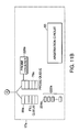
- FIGS. 11, 11 A and 11 B depict one of the central processing units of the computer system of FIG. 1, together with a probe counter and a plurality of victim release counters associated with that CPU and included in the address control chip;
- FIG. 12 depicts a flow diagram of the operation of the probe counter and the victim release counters of FIG. 11;
- FIG. 13 depicts a block diagram of several central processing units of the computer system of FIG. 1 together with probe counters and victim release counters associated with those CPUs and included in the address control chip;
- FIG. 14 depicts a flow diagram illustrating a problem solved by clean-victim commands executed on the computer system of FIG. 1;
- FIG. 15 depicts a flow diagram of the operation of clean-victim commands executed on the computer system of FIG. 1;
- FIG. 16 depicts a further enhancement to the operation of clean-victim commands as implemented on one of the central processing units of the computer system of FIG. 1;
- FIG. 17 depicts a flow diagram of the enhancement to the operation of clean-victim commands as implemented on one of the central processing units of the computer system of FIG. 1 .
- a multiprocessor computer system 10 is shown to include four processor modules 11 a , 11 b , 11 c , and 11 d , each including a central processing unit (CPU).
- processor modules 11 a , 11 b , 11 c , and 11 d each including a central processing unit (CPU).
- CPU central processing unit
- Alpha® 21264 central processing unit chips manufactured by Digital Equipment Corporation® are used however other types of processor chips capable of supporting the invention may alternatively be used.
- the multiprocessor computer system 10 includes a memory 42 which may comprise a number of memory modules 42 a - 42 d , a system control logic 18 and an I/O processor module (IOP) 14 .
- the IOP 14 is coupled to an I/O bus 14 a , such as a Peripheral Computer Interconnect (PCI) bus for transferring data to and from the multiprocessor computer system 10 and external devices as set forth in the applicable PCI standards.
- PCI Peripheral Computer Interconnect
- IOP tag store 14 b for storing addresses and coherency status information relating to data that is being used by the external devices.
- the IOP 14 , processor modules 11 a - 11 d and memory modules 42 are coupled to the system control logic 18 by bi-directional data links 16 a - 16 i and address links 20 a - 20 e .
- the QSD devices 15 of the system control logic 18 provide a switch interconnect for data sent between the processor modules 11 a - 11 d , memory modules 42 a - 42 d and IOP 14 .
- the QSD devices 15 are slaved to the control signal sent from the address control chip 17 .
- FIG. 1 shows four QSD devices included in the system control logic 18 , with each QSD device controlling a portion of the data path. Other embodiments may use more QSD devices depending on the width of the data path that is implemented.
- the system control logic 18 includes an address control chip (QSA) 17 and data slice chips (QSDs) 15 .
- the address control 17 is a master controller for all command paths to processor modules 11 a - 11 d , and to the IOP module 14 .
- the address control chip 17 provides control signals to the QSD devices 15 for controlling the switch interconnect and the data interconnect between the QSDs and each of the processor modules.
- the address control chip 17 also includes a central arbitration circuit 60 for determining the order in which processor requests are serialized and receive access to a remote duplicate tag store 23 and to main memory 42 .
- the address control chip 17 serializes commands, such that one per cycle wins arbitration and is asserted on the arbitration (Arb) bus 21 .
- Address control chip 17 further includes fill queues 80 a - 80 d and probe queues 79 a - 79 d .
- Each probe and fill queue is associated with one of the processor modules 11 a - 11 d .
- Each probe and fill queue provides probe messages and fill messages, respectively, in a first in first out (FIFO) manner to the processor module to which it is coupled.
- a probe message, or simply a probe is issued by the system control logic in response to a request by a processor module or the IOP 14 to retrieve (probe read message) or change the status of (probe invalidate message) a most recent version of a data element that is stored in another processor's cache memory.
- the address control chip 17 performs a duplicate tag store lookup operation for the data element targeted by the command. This lookup operation indicates which CPU has a most up-to-date copy of the targeted data element stored in its cache or, alternatively, indicates that main memory 42 contains the most up-to-date copy. If the command that won arbitration is a request to retrieve a copy of the targeted data (a readmiss command) the address control chip 17 uses the result of the duplicate tag store lookup operation to determine whether to retrieve it from main memory or from another CPU's cache. If it must retrieve the data from another CPU's cache it does so by issuing a probe read message to that CPU through the associated probe queue. When the probe message reaches a point in the CPU where the target address of the probe can be compared against the entries of its local tag store, it is referred to as being at the “top” of that probe queue and can be processed by the CPU.
- the associated processor In reply to a probe message that has reached the top of the probe queue, the associated processor initiates a probe response in which the system control logic 18 is notified that the probe message's target address has been compared against the entries of the local tag store.
- the probe response indicates that the data targeted by the probe message is ready to be transferred to the system control logic 18 .
- the system control logic 18 then commands the central processing unit to transfer the data and incorporates it in a fill message.
- the fill message is placed on the fill queue of the central processing unit that issued the associated readmiss command, i.e. the requesting CPU, such that the data will be stored in the cache memory of the requesting CPU.
- the shared, serially accessed duplicate tag store (dtag) 23 is used to maintain data coherency within the multiprocessor computer system 10 .
- the duplicate tag store 23 receives commands from the address control chip 17 via arb bus 21 and transfers information to the address control chip 17 via bus 19 .
- the duplicate tag store 23 is further coupled to memory modules 42 a - 42 d by arb bus 21 and is partitioned into a plurality of storage locations for retaining the tag addresses of data elements stored in the backup cache memories of each processor module 11 a - 11 d .
- These tag addresses are referred to as backup cache tags or duplicate tags and allow the address control chip 17 to quickly determine the state of each data element stored in a given processor module's cache memory. Based on this information, the address control chip 17 will issue probe messages only to processors that have a most up-to-date copy of the requested data.
- processor module 11 a representative of processor modules 11 b - 11 d of multiprocessor computer system 10 , is shown in more detail.
- Processor module 11 a is shown coupled to its associated probe queue 79 a and fill queue 80 a via bus 20 a .
- processor module 11 a includes an internal probe queue 81 a that functions as an extension of probe queue 79 a .
- Processor module 11 a also includes a central processing unit (CPU) 12 a , a backup cache 29 a , and a backup cache tag store 30 a .
- Data cache 22 a is typically smaller and faster than backup cache 29 a .
- the tag portion of each backup cache entry's address, as well as its status flags, are stored in tag store 30 a .
- the status flags include a dirty bit, a valid bit, and a shared bit.
- the valid bit indicates that the data is the most recent version of the particular data element.
- the dirty bit indicates that the data has been modified since it was retrieved and thus indicates that the CPU coupled to the cache is the “owner” of the data. Being the owner of a data element means that the coupled CPU is responsible for servicing all requests that target that data until another processor takes ownership of the data, or until the command to write the data back to main memory wins arbitration.
- the shared bit indicates that another CPU also has an identical copy of the data element stored in its cache.
- the status flags stored in tag store 30 a are similar to the status “code” stored in duplicate tag store 23 (shown in FIG. 1 ). That status code indicates whether the entry is valid, invalid, dirty-probed, or dirty-not-probed. As in tag store 30 , the valid and invalid portions of the status code indicate whether or not the associated CPU has an unmodified copy of the data. The dirty-probed portion of the status code indicates that the associated processor has a dirty copy of the data and that a probe read message has been previously issued to that CPU to retrieve a copy of it. Likewise, the dirty-not-probed portion of the status code indicates that the associated CPU has a dirty copy of the data but a probe read message has not previously been issued to the CPU to retrieve it. Accordingly, the status information stored by tag store 30 and by duplicate tag store 23 are not identical.
- the CPU 12 a includes several groups of logic that enable it to perform the major operations that the computer system 10 requires.
- the Ibox 34 a or instruction fetch and decode unit, controls instruction pre-fetching, instruction decoding, branch prediction, instruction issuance, and interrupt handling.
- the Ebox 36 a or integer execution unit, handles the functions of addition, shifting, byte manipulation, logic operations, and multiplication for integer values stored in the system. These same operations, for floating point values, are controlled by the Fbox 38 a , or floating point execution unit.
- the Mbox 40 a or memory address translation unit, translates virtual addresses, generated by programs running on the system, into physical addresses which are used to access locations in the computer system 10 .
- the Ebox 36 a and Fbox 38 a operate on data items and are primarily coupled to Data cache 22 a via busses 25 a and 26 a respectively. Also, Mbox 40 a and Ibox 34 a are coupled to the Instruction cache 24 a via busses 27 a and 28 a respectively.
- the Cbox 30 a includes logic for controlling the backup cache 29 a , memory related external interface functions, and all accesses initiated by the Mbox 40 a .
- the Cbox 30 a also includes victim data buffers 78 a , a victim address file (VAF) 87 a , and a miss-address file (MAF) 86 a for operations related to retrieving data elements.
- the victim data buffers 78 a store data elements that have been evicted from backup cache 29 a .
- the VAF 87 a stores the addresses of data elements stored in each victim data buffer.
- the MAF 86 a stores a copy of each command that central processing unit 11 a issues to the system but which has not yet completed.
- the Cbox 30 a also includes a path for probe and fill messages to enter the central processing unit 11 a and operate on specified data stored in che memory or in the victim data buffers.
- the path is an extension of probe queue 79 a and fill queue 80 a and includes an internal probe queue 81 a for probe messages, and a bypass path for fill messages, as will be described in more detail below.
- FIG. 3 a simplified depiction of a multiprocessor computer system 10 is shown to include a plurality of processor modules 11 a - 11 d in relation to address control chip 17 .
- Each processor module 11 a - 11 d is minimally shown to include a Central Processor Unit 12 a - 12 d , and a backup cache 29 a - 29 d .
- Each CPU 12 a - 12 d is shown to include a miss-address file (MAF) 86 a - 86 d , a set of victim data buffers (VDB) 78 a - 78 d , an internal probe queue 81 a - 81 d and a primary data cache 22 a - 22 d as described above.
- MAF miss-address file
- VDB victim data buffers
- the processor modules 11 a - 11 d are coupled to the address control chip 17 which includes the central arbitration circuit 60 , and a probe and fill queue pair ( 79 a - 79 d and 80 a - 80 d ) for each processor module 11 a - 11 d.
- a central processing unit 12 a - 12 d will attempt to retrieve data elements from its primary data cache 22 a - 22 d and backup cache 29 a - 29 d before issuing a command to the system control logic to retrieve the requested data. If the memory block that contains the requested data is not stored in the CPU's cache, a cache miss occurs and the data must be retrieved from another source such as main memory 42 or another CPU's cache.
- the CPU In order to retrieve the data from a source other than an attached cache, the CPU issues a command to the system control logic 18 . If the CPU only needs to access the data, it issues a readmiss command to the system control logic 18 . That command will cause the system control logic 18 to retrieve the most up-to-date copy of the requested data element and store it in the CPU's cache. The associated status information will be updated to indicate that the data is in an unmodified state. If the CPU needs to modify the data, it issues a read-miss-modify command to the system control logic 18 .
- the read-miss-modify command will cause the system control logic 18 to retrieve an up-to-date copy of the data, invalidate all other copies of that data via a probe invalidate message, store it in the requesting CPU's cache and update the associated status information to indicate that the data is in an exclusive modified state.
- a data element is in an exclusive state it means that it is stored only in that cache and, therefore, is considered the most up-to-date version in the computer system.
- a readmiss or read-miss-modify command is issued, it is input to central arbitration circuit 60 .
- Central arbitration circuit 60 includes an arbitration algorithm for determining the order in which the command will gain access to the duplicate tag store 23 and main memory 42 . Such arbitration algorithms can include round-robin arbitration which is well known in the art and will not be explained further. Further, central arbitration circuit 60 operates responsive to the number of probe messages stored on each of the probe queues. When one of the probe queues becomes “full”, i.e. when each of its entries is filled with a pending probe message, the central arbitration logic is stalled by the address control chip 17 . When the central arbitration logic 17 is stalled, commands that are issued to the address control chip 17 , from the central processing units, will not be input to the central arbitration circuit until the full probe queue has a predetermined number of free locations.
- the central arbitration circuit 60 will be prevented from issuing any more probe messages to the system serialization point. For example, when the probe queue is full, a full flag coupled to the probe queue, is set. At this point the central arbitration circuit 60 will be prevented from issuing further probe messages to the system serialization point. Eventually, as the associated central processing unit processes probe messages that reach the top of the probe queue, entries of the probe queue will be made available to hold further probe messages. When a predetermined number of entries are available, an almost-full flag will be set. Responsively, central arbitration circuit 60 will resume normal operation.
- the system control logic 18 When a readmiss or read-miss-modify command wins arbitration, the system control logic 18 performs a lookup operation on the entries of duplicate tag store 23 to determine if a most up-to-date version of the requested data is stored in one of the backup cache memories 29 a - 29 d of the Central Processor Units 11 a - 11 d . Concurrently, an access of main memory 42 is initiated. If none of the backup cache memories 29 a - 29 d have a most up-to-date copy of the data, it is retrieved from main memory 42 .
- a corresponding probe read message (and for read-miss-modify commands, a probe read-invalidate message) is placed on the probe queue 79 a - 79 d of the central processing unit that has the requested data stored in its backup cache 29 a - 29 d .
- the central processing unit storing the requested data replies to the probe read message by initiating a probe response.
- the probe response indicates to the system control logic 18 that the requested data is ready to be accessed.
- the system control logic obtains a copy of the data and incorporates it in a fill message placed on the fill queue of the requesting CPU. When the fill message reaches the top of the fill queue, the data is stored in cache.
- the command was a read-miss-modify command
- the status of any other entry in the duplicate tag store 23 that matches the data targeted by the command is changed to invalid via a probe invalidate message issued to each CPU other than the one which is supplying the data.
- a probe read-invalidate message is issued to the CPU that owns the data and a probe invalidate message is issued to other CPUs that are storing copies of the data.
- a probe read-invalidate message retrieves a copy of the data from a CPU and also changes its status in that CPU to invalid. The copies of the data in that CPU and all other CPUs are invalidated because the requested data is to be modified by the requesting CPU.
- the modified value will thereafter be the only valid copy of the data and, because of the invalidation of the other CPU's entries in duplicate tag store 23 , the system will no longer issue probe read messages to retrieve the data from those sources.
- future probe messages are directed to the CPU that issued the read-miss-modify command so that the up-to-date version of the data is retrieved from its cache memory.
- a data element is already stored at that location the CPU needs to displace the stored data to make room for the requested data.
- Such evicted data is referred to as “victim” data.
- the CPU writes victim data back to memory by issuing a “victim” command along with the associated readmiss or read-miss-modify command.
- the combination of commands is referred to as a readmiss/victim or read-miss-modify/victim command pair.
- the victim data is stored in a victim data buffer in the CPU.
- displacing the modified data to a victim data buffer 77 storage space is released in the cache while allowing a copy of the victim data to be accessed until all probe messages that were issued to the CPU before the associated victim command won arbitration have passed through the probe queue 79 .
- Probe messages and fill messages pass through separate and independently operating probe queues and fill queues before being input to the CPU to which they were issued. Probe messages and fill messages also require access to different sets of system resources. Fill messages require access to the CPU's command bus, data bus and cache. Probe messages, on the other hand, require access to the CPU's address bus, data bus and internal buffer resources. Although these sets of system resources overlap to some extent, the specific dependencies are unique, i.e. probe messages use resources that drive data to the system control logic while fill messages use resources that drive data from the system control logic to a CPU. As a result of this difference in resources, probe messages in the probe queue may make progress slower than fill messages in the fill queue, and vice versa.
- the most likely condition is that the probe messages will progress slower than the fill messages because of the probe message's dependence on the internal processor buffer resources. Accordingly, by segregating the two types of messages, the faster executing fill messages are not delayed by the slower executing probe messages and, in certain circumstances, vice versa. Further, since the speed of a computer system is largely determined by the time it takes to retrieve data, such an architecture greatly improves the rate at which requested data is stored in cache and therefore improves system performance.
- the probe messages and the fill messages can execute at different speeds.
- a problem arises whenever a probe read message reaches the top of the probe queue 79 before a fill message containing the requested data reaches the top of the fill queue with that data.
- the data is not present to satisfy the probe message, and therefore the probe queue 79 is stalled until the data is retrieved and stored in the cache.
- System performance can be improved by allowing individual probe queues to be stalled without stalling the entire system, i.e. by distributing such data dependent probe queue stalls.
- a series of probe messages targeting the same data can be chained together, e.g. a first probe message can be issued to a first CPU which has an associated second probe message that is in the process of retrieving the requested data from a second CPU.
- a first CPU issues a read-miss-modify command to the system control logic, concurrently with a readmiss or read-miss-modify command issued from a second CPU that references that same data element, and wherein the most up-to-date copy of the data element resides in a third CPU's cache. If the read-miss-modify command from the first CPU is issued to the system serialization point before the readmiss command from the second CPU, then the duplicate tag store lookup for the read-miss-modify command from the first CPU will cause a first probe read message to be issued to the third CPU. The system control logic then updates the duplicate tag store to indicate that the first CPU now has the most up-to-date copy of the data in the system.
- the associated duplicate tag store lookup will detect the duplicate tag store update from the first CPU's read-miss-modify command and a second probe read message will be issued to the first CPU.
- This second probe read message may reach the top of the first CPU's probe queue before the fill message associated with the first probe read message reaches that same CPU. Since the fill message associated with the first probe read contains the data required by the second probe read, the second probe read cannot be serviced.
- each CPU 11 a - 11 d includes a miss address file which stores references to each data element for which that CPU has issued a readmiss or read-miss-modify command that has not completed.
- the attached processor module 11 a - 11 d will not process a probe message that reaches the top of probe queue 79 if the associated miss address file 86 a - 86 d contains a reference for the data targeted by that probe message.
- the central processing unit 12 a - 12 d compares the target address of the probe message with each entry in its MAF 86 a - 86 d . If a match is detected the processor stalls the probe queue by allowing the probe message to remain at the top of the probe queue without being processed until the requested data is returned via a fill message and the corresponding entry in the MAF is deleted. Meanwhile, the other probe queues in the system continue to operate normally. Therefore the architecture of the computer system 10 prevents the above mentioned problem from occurring by allowing individual probe queues to be stalled by their associated CPUs without stalling the entire system.
- FIG. 4 a flow diagram depicts the functionality of the computer system's central processing units and their associated logic with respect to issuance of a readmiss or read-miss-modify command and the corresponding probe read message.
- a multiprocessor computer system 10 such as depicted in FIG. 3, comprised of a plurality of CPUs 12 a - 12 d (hereinafter CPU 1 , CPU 2 , CPU 3 , and CPU 4 respectively).
- CPU 1 first issues a read-miss-modify command for data block A (step 100 ) to the system control logic 18 .
- the address control chip 17 determines that the most up-to-date copy of data block A is stored in main memory 42 .
- the address control chip 17 updates the corresponding entry in the duplicate tag store 23 , retrieves a copy of data block A from main memory 42 and incorporates it in a fill message placed on fill queue 80 a (step 102 ). Following these events, CPU 2 also issues a read-miss-modify command targeting data block A (step 104 ). When that read-miss-modify command for data block A wins arbitration, the address control chip 17 performs a lookup operation wherein the duplicate tag store 23 compares the data block's address with each of its entries, and sends the result to the address control chip 17 (step 106 ).
- the address control chip 17 is informed that CPU 1 has a dirty copy of the data and therefore updates the appropriate duplicate tag store entries to indicate that CPU 2 now has an exclusive, modified copy of data block A and issues a probe read and probe read-invalidate message to retrieve the data from CPU 1 and invalidate the remaining copy.
- the read-miss-modify command from CPU 2 has just won arbitration and hence has just begun the process of retrieving data block A
- the associated tag in duplicate tag store 23 indicates that CPU 2 is the only owner, that the data has been retrieved and that it has been modified (step 108 ). Therefore the duplicate tag store entry is updated based upon the order of command issuance on the arb bus rather than the order of command completion.
- CPU 3 Following the issuance of the read-miss-modify command from CPU 2 , CPU 3 also issues a read-miss-modify command for data block A (step 110 ).
- the address control chip 17 will determine from the duplicate tag store lookup that data block A can be retrieved from CPU 2 's cache. Such a determination is based upon the fact that the corresponding duplicate tag store entry was changed to indicate that CPU 2 is the owner of data block A. However, CPU 2 is still in the process of retrieving the data from the CPU 1 's cache.
- the duplicate tag store entries were updated to indicate that CPU 3 owns data block A (step 112 ).
- CPU 1 issues a probe response and the address control chip 17 places a fill message containing data block A on the fill queue for CPU 2 .
- the probe read message associated with the read-miss-modify command issued from CPU 3 , reaches the top of CPU 2 's probe queue before the fill message associated with the read-miss-modify command issued from CPU 2 returns the requested data (step 114 ).
- the present invention includes a mechanism for preventing a system-wide stall condition by allowing each probe queue to be stalled individually until the requested data is retrieved, while also retaining cache coherency.
- the probe read message associated with the read-miss-modify command from CPU 3 reaches the top of CPU 2 's probe queue, it is compared against the entries of the associated miss-address file 86 b to determine if a command has been issued by CPU 2 to retrieve data block A (step 116 ). Because the miss address file 86 b indicates that CPU 2 has an outstanding read-miss-modify command to retrieve data block A, the probe message will remain unprocessed (the probe queue is stalled) until the data is actually stored in cache (step 118 ).
- the method of the present invention specifies that if a probe read message arrives at the top of a CPU's probe queue, and the CPU has an outstanding readmiss or read-miss-modify command for the same address, as evidenced by a corresponding miss-address file entry, the CPU's probe queue is stalled until the associated fill message is received and the data stored in cache. Using this method, only the probe queue in question is stalled, while the rest of the system can continue normal operations.
- probe messages are issued to a CPU based upon the order that commands win arbitration rather than the order of command completion, more than one probe message, targeting the same data block, can be “chained” together.
- a set of probe messages are considered chained together when each has been issued to a CPU that is in the process of retrieving the targeted data.
- each probe message waiting for that CPU to retrieve the data is serviced. Where a command reaches the top of a probe queue before the requested data is retrieved, it is stalled by the associated CPU until the associated fill message retrieves the data.
- a probe message targeting data block B can be placed on a probe queue associated with a first CPU which is in the process of retrieving data block B from a second CPU which is also in the process of retrieving data block B from a third CPU, and so on.
- each CPU receives a copy of the data, its probe queue is restarted, the probe message at the top of the probe queue is serviced, and the data can be passed to the next CPU in turn.
- this mechanism can only work in a system having a duplicate tag store 23 or similar logic that represents the status of data stored in the associated CPU's cache, otherwise the system will deadlock.
- FIG. 5 a block diagram depicts an optimization of the present invention for allowing distributed data dependent stalls.
- Such an optimization saves cycle time otherwise used to compare the address of a requested data element with each of the miss address file entries.
- the duplicate tag store is checked to determine that the targeted CPU appears to have an up-to-date version of the requested data in its cache (step 119 ).
- the optimization is that if a probe message reaches the top of that CPU's probe queue but the data is not stored in the cache or in a victim data buffer (step 120 ), the probe queue is stalled without checking the miss-address file for an outstanding access which targets the requested data (step 121 ).
- Such an embodiment presumes that the probe message would not have been sent to the CPU if there had not been an outstanding readmiss or read-miss-modify command issued to retrieve the data, and hence a corresponding miss address file entry.
- This embodiment only works where each CPU always updates the duplicate tag store 23 before invalidating data elements, and where the duplicate tag store 23 is a perfect filter.
- a perfect filter only indicates that a CPU is the owner of a data element if it has already retrieved the requested data or has an outstanding request to retrieve the data element which will complete before the probe message reaches the top of the associated probe queue.
- a CPU 12 a is further shown coupled to a primary data cache (Dcache) 22 a , and a backup cache (Bcache) 29 a . Because the Dcache 22 a is located on the CPU chip 12 , its interface is closely coupled to the CPU 12 a and therefore data can be accessed using a very short cycle.
- Dcache primary data cache
- Bcache backup cache
- the Bcache 29 a is located off the CPU chip 12 a and includes memory elements that are functionally slower than those that comprise the Dcache 22 a . Because of the location and relative speed of Bcache 29 a , data access is slower but storage capacity is greater than Dcache 22 a and therefore a greater probability exists that a specified data block will be stored therein.
- CPU 12 a uses one of a variety of replacement algorithms to determine when to displace the least useful data blocks. By replacing the least useful data blocks with those having a higher potential of being accessed, the overall performance of the computer system is increased.
- the least useful cache data blocks are replaced when the associated CPU requires access to data that is not stored in the cache. In such a case, before a command to retrieve the data block containing the required data is issued to the system control logic, a determination is made as to where in cache the new data will be placed. If another data block is stored in that location, the existing data block is removed, or “evicted”. The data that is evicted is referred to as “victim” data.
- victim data buffers 78 a Associated with each cache memory is a set of buffers, referred to as victim data buffers 78 a .
- the victim data that is displaced from the cache is stored in one of these victim data buffers 78 a , and its address stored in the victim address file, before it is written back to main memory 42 , before it is discarded, or while that data is required to satisfy probe messages that were issued before an associated victim command won arbitration in arbitration circuit 60 .
- FIG. 2 depicts a write back cache configuration although it will be apparent to one of ordinary skill in the art that the present invention is not limited to a single cache architecture.
- Modified data stored in cache is referred to as “modified” or “dirty” because its value is different than the copy of the data stored in the corresponding main memory location.
- status information in tag store 30 a and in duplicate tag store 23 associated with the modified data indicates whether the data held in the cache is dirty and whether the owner CPU has the only current version of the data in the computer system 10 (i.e. that the CPU has the most up-to-date copy of the data).
- a cache miss When a cache is accessed to retrieve data that is not stored therein, referred to as a cache miss, the data block that contains the data element is retrieved from another source, i.e. main memory or another CPU having a most up-to-date copy of the data block. Retrieval of the data block is performed via the issuance of a readmiss or read-miss-modify command, to the system control logic. When the associated cache miss is detected, the dirty data block is evicted from the cache.
- a readmiss or read-miss-modify command and a victim command (referred to as a readmiss/victim or read-miss-modify/victim command pair) is issued to the system control logic to retrieve the requested data and to write the victim data back to main memory 42 .
- the duplicate tag store update operation associated with that command pair modifies the duplicate tag store entry associated with the requested data element to indicate that the associated victim data is no longer an element of the requesting CPU's cache and to indicate that the requested data element is stored in the requesting CPU's cache. Also, the system control logic lengthens the main memory access associated with the readmiss command to include a victim write cycle for writing the victim data to main memory.
- the readmiss command wins arbitration before the readmiss/victim command pair the results of the duplicate tag store lookup associated with the readmiss command will indicate that the most up-to-date copy of the data requested by the second CPU is stored in the first CPU.
- the system control logic will responsively issue a probe message to the first CPU. In this situation it is essential that the first CPU is able to provide copies of the modified victim data to both the victim write to main memory 42 and to the probe message, to maintain proper system operation.
- Providing data in response to readmiss/victim command pairs and probe messages is further complicated due to the interactions between fill and probe messages.
- Fill messages and probe messages travel in independent fill and probe queues between the arbitration unit of the system control logic and the targeted CPU. Because of the difference in progress speeds, a fill message can return data that is targeted by the readmiss command portion of a readmiss/victim command pair, to the issuing CPU before a probe message, issued by the system control logic prior to the issuance of the readmiss/victim command, reaches the top of an associated probe queue. This fill will overwrite the copy of the victim data in the issuing CPUs cache. If the probe message requires access to a copy of the victim data associated with the readmiss/victim command pair, the CPU and/or system control logic must therefore provide a copy of this data from a source other than the cache.
- a victim data buffer is loaded with a copy of the victim data element prior to issuing the readmiss/victim command pair to the system control logic. That copy of the victim data is kept in the victim data buffer until the system control logic determines that all probe messages that require a copy of the victim data have been satisfied and that the main memory victim write operation has been satisfied.
- This determination is made using a three step process. The first step involves a determination of whether every probe message in the system, that requires data stored in the victim data buffer, has performed an “address comparison”.
- the address comparison is a comparison of the target address of each probe message against the address of the victim data, to indicate whether the probe message actually requires a copy of the victim data.
- the second step involves determining, in the case where the address of at least one probe matched the address of the victim data buffer element, that a copy of the victim data has been transferred to the system in response to the last probe that required the data.
- the third step involves monitoring the victim write operation, that writes the victim data to main memory, and monitoring each probe that requires access to the data stored in the victim data buffer to determine when all have been serviced.
- the present invention simplifies the second step of the above mentioned determination through the use of flags referred to as a victim valid bit and a probe valid bit associated with each victim data buffer in the system.
- duplicate tag store 23 responsively checks its entries to determine if another CPU's cache has an up-to-date copy of the data. If no other CPU has an up-to-date copy, the system control logic retrieves the data from memory 42 and passes it back to the requesting CPU via a fill message. When the victim command portion of the readmiss/victim or read-miss-modify/victim command pair wins arbitration, the data is written back to main memory but a copy remains in the victim data buffer to service pending probe messages.
- the system control logic employs a buffer clearing mechanism, such as a victim release counter described hereinbelow, to determine when to send a command to the CPU to clear the victim valid bit.
- the command issued from the system control logic to clear the victim valid bit 82 is referred to as the “release victim valid bit” (RVB) command.
- the buffer clearing mechanism guarantees that the victim valid bit 82 remains set during the period of time between when the data is transferred to the victim data buffer 78 until all probe messages that were issued from the system control logic prior to the victim command winning arbitration in the system control logic, have had an associated probe response sequence initiated and until a copy of the victim data has been transferred to the system control logic to be written to main memory. Until the victim valid bit 82 is cleared the victim data buffer 78 cannot be de-allocated, and the CPU maintains the status information associated with the data stored in the victim data buffer.
- probe valid bit 84 a Another flag associated with each of the victim data buffers 78 a , is referred to as a “probe valid bit” 84 a .
- the probe valid bit 84 a associated with a victim data buffer, may be set as a probe message is processed by a CPU and prior to the issuance of an associated probe response. If the requested data's address matches an entry in the victim address file 87 a , indicating that the requested data is held in a victim data buffer, then the probe valid bit associated with that victim data buffer will be set.
- the system control logic 18 When a probe response is issued from the CPU indicating that the data is ready to be accessed, the system control logic 18 will first obtain a copy of the data in the victim data buffer and then issue a “release probe valid bit” command to the CPU to clear the probe valid bit. If another probe message subsequently reaches the top of the probe queue and targets a data block stored in the victim data buffer, then the probe valid bit will again be set. If the probe message at the top of the probe queue targets data stored in a victim data buffer that already has the probe valid bit set, the probe message will not be processed until the bit is cleared, i.e. the probe queue will be stalled.
- a first CPU performs a lookup operation of its cache to access a data element required for an ongoing operation (step 140 ).
- a cache miss occurs (step 142 ) and the CPU determines that another data block is stored in the cache location where the requested data will be placed when it is retrieved.
- the CPU then evicts the victim data from the cache to a victim data buffer (step 144 ).
- the CPU initiates the retrieval of the requested data by issuing a readmiss command and a victim command, i.e. a readmiss/victim command pair (step 146 ).
- duplicate tag store 23 determines that a most up-to-date copy of the data is stored in the a second CPU's cache (step 148 ).
- Address control chip 17 responsively issues a probe read message to the second CPU (step 150 ).
- the probe read message is placed on the probe queue for that CPU.
- the second CPU evicts the requested data from the cache into a victim data buffer and sets that buffer's victim valid bit 82 a (step 152 ).
- the CPU compares the target address of the probe message with the entries of the VAF 87 a .
- a probe valid bit 84 a associated with the victim data buffer is also set (step 154 ). If another probe message that targets the same data subsequently reaches the top of the probe queue, it must wait until the probe valid bit is cleared before it can access that data. While the probe bit is set, the victim data can be written back to main memory since a copy of the data will remain in the victim data buffer for the pending probe message to access.
- the system control logic When the system control logic receives the probe response message from the second CPU it obtains a copy of the requested data which it will incorporates in a fill message and returns to the first CPU. The system control logic will also issue a release probe valid bit command to the second CPU that clears the probe valid bit 84 a for the victim data buffer (step 156 ). Further, when the associated victim release counter indicates that all probe messages that were issued before the victim command won arbitration have had a probe response initiated and the victim data has been written back to memory 42 , the system control logic issues a release victim valid bit command to clear the victim valid bit 82 a (step 158 ).
- probe valid bit 84 a and the victim valid bit 82 a data can remain in the victim data buffer 78 after the victim data is written back to memory and after the associated victim release counter mechanism indicates that all probes have been compared against the victim data buffers. Only after the probe message accesses the data, and after the victim valid and probe valid bits are cleared, will the buffer be de-allocated (step 160 ). Such an embodiment allows probe data movement to complete independent of writing victim data back to main memory and independent of performing probe address comparisons.
- independent victim buffer and probe buffer release control invention is not limited to the system configuration depicted in FIG. 1 .
- present invention applies equally to a variety of system configurations including single processor systems and systems that do not implement a duplicate tag store.
- multiprocessor computer system 138 of FIG. 7 which includes the same components as multiprocessor computer system 10 (see FIG. 1) except for duplicate tag store. Because multiprocessor computer system 138 does not include a remote duplicate tag store, the system control logic cannot determine whether a given data element is stored in a CPU's cache without actually accessing that cache. Accordingly, in response to each readmiss/victim or read-miss-modify/victim command pair that wins arbitration, each CPU receives a request from the system control logic for the requested data element. In such a system the victim valid bit is set when the victim data element is stored in a victim data buffer. The release victim valid bit command is issued after the victim command associated with the victim data element wins arbitration and that victim data is written into main memory. The probe valid bit operates in the same manner as described above with respect to multiprocessor computer system 10 , and the victim data buffer is deallocated when both the probe valid bit and victim valid bit are cleared.
- FIG. 8 depicts the operation of the victim valid bit and the probe valid bit in multiprocessor computer system 138 .
- a first CPU performs a lookup operation of its cache to access a data element required for an ongoing operation (step 162 ).
- a cache miss occurs (step 164 ) and the CPU determines that another data block is stored in the cache location where the requested data will be placed when it is retrieved.
- the first CPU then evicts the victim data from the cache to a victim data buffer (step 166 ).
- the first CPU initiates the retrieval of the requested data by issuing a readmiss command and a victim command, i.e. a readmiss/victim command pair (step 168 ).
- a probe message is placed on the probe queue of each CPU of multiprocessor computer system 138 , targeting the requested data element (step 170 ).
- the second CPU evicts the requested data from the cache into a victim data buffer and sets that buffer's victim valid bit 82 a (step 172 ).
- the second CPU compares the target address of the probe message with the entries of its VAF 87 . Upon detecting a match, a probe valid bit 84 associated with the victim data buffer is also set (step 174 ).
- probe valid bit is cleared before it can access that data. While the probe bit is set, the victim data can be written back to main memory since a copy of the data will remain in the victim data buffer for the pending probe message to access.
- the system control logic 18 When the system control logic receives the probe response message from the second CPU, indicating that a copy of the data is ready to be accessed, the system control logic 18 obtains a copy of the requested data which it incorporates in a fill message and returns to the first CPU. The system control logic will also issue a release probe valid bit command to the second CPU that clears the probe valid bit 84 for the victim data buffer (step 176 ). Further, when the victim data is written into main memory 42 , the system control logic issues a release victim valid bit command to clear the victim valid bit 82 (step 178 ). Only after the probe message accesses the requested data, and after the victim valid and probe valid bits are cleared, will the buffer be de-allocated (step 180 ). Such an embodiment allows probe data movement to complete independent of writing victim data back to main memory and independent of performing probe address comparisons.
- FIG. 9 includes a single processor module 11 a similar to that shown in FIG. 2, and an I/O processor (IOP) for transferring data to and from the multiprocessor computer system 10 and external devices.
- the central processing unit 11 a and the IOP are coupled to system control logic 182 which provides a data interconnect to main memory 42 .
- system control logic 182 which provides a data interconnect to main memory 42 .
- the victim valid bit is set when a victim data element is stored in a victim data buffer.
- the release victim valid bit command is issued after the victim command associated with the victim data element wins arbitration and that victim data is written into main memory.
- the probe valid bit operates in the same manner as described above with respect to multiprocessor computer system 10 , and the victim data buffer is deallocated when both the probe valid bit and victim valid bit are cleared.
- Prior art CPUs have typically stored data in their victim data buffers only until victim data has been transferred to the system control logic 18 or main memory 42 .
- system control logic 18 or main memory 42 To service outstanding probes many prior art systems implement a duplicate copy of the victim data buffers in the system control logic.
- Such a solution is overly complex and requires unnecessary redundancy.
- the present invention allows, by means of a scheme for allowing a copy of victim data to remain in a victim data buffer after another copy has been read from it, probes to be serviced using the victim data buffers that are present in each CPU in multiprocessor computer system 10 .
- a victim valid bit associated with each victim data buffer provides one method for allowing the buffer to remain allocated after data has been read from it. For example, referring now to the flow diagram of FIG. 10A, when a data element is evicted from cache (step 122 ) the associated CPU allocates a victim data buffer (step 123 ) to store that victim data. The CPU transfers the victim data to the victim data buffer (step 124 ) and sets the associated victim valid bit (step 125 ). A readmiss/victim or read-miss-modify/victim command pair is subsequently issued to the system control logic 18 and input to arbitration circuit 60 (Step 126 ). Upon winning arbitration, the victim command will cause the data stored in the victim data buffer to be written to main memory (Step 127 ).
- the victim valid bit After issuance of a release victim valid bit command from the system control logic, the victim valid bit is cleared and the buffer subsequently deallocated (step 128 ).
- the release victim valid bit command is issued when some number of probe messages that have passed the serialization point of the computer system prior to the associated victim command have searched the victim data buffers for the data element they require and, if necessary, obtained a copy of the data element. Accordingly, the present invention allows the data read operation to operate independently from the victim data buffer release operation by causing the victim data buffer to remain allocated, and the central processing unit to maintain the data's coherency information, until the victim valid bit is cleared even though the victim data was written to main memory when the victim command passed the serialization point.
- a flow diagram depicts the operation of a further embodiment of the present invention in a computer system that does not include a duplicate tag store remote from the central processing units.
- the victim data buffer is deallocated at a point in time that is based on a current operating state of the system. For example, consider a data element that is stored in a victim data buffer having the associated victim valid bit set (Step 130 ).
- the system control logic cannot determine whether a given data element is stored in a CPU's cache without actually accessing that cache.
- each CPU receives a request from the system control logic (Step 134 ).
- the release victim valid bit command is issued, and the victim valid bit cleared, after the victim command wins arbitration and the victim data is written into main memory (Step 136 ).
- the copy of the victim data stored in the victim data buffer remains accessible by pending requests until the main memory write operation is in the process of executing.
- the coherency state is maintained by the CPU until the data is in main memory 42 . Accordingly, there is no need for coherency maintenance logic in any of the parts of the system control logic 18 which the victim data passes through on the way to main memory.
- FIG. 9 includes a single processor module 11 a similar to that shown in FIG. 2, and an I/O processor (IOP) for transferring data to and from the multiprocessor computer system 10 and external devices.
- IOP I/O processor
- the central processing unit 11 a and the IOP are coupled to system control logic 182 which provides a data interconnect to main memory 42 .
- system control logic 182 provides a data interconnect to main memory 42 .
- the victim valid bit is set when a victim data element is stored in a victim data buffer.
- the release victim valid bit command is issued after the victim command associated with the victim data element wins arbitration and that victim data is written into main memory.
- processor module 11 a of multi-processor computer system 10 is shown coupled to address control chip 17 .
- Address control chip 17 is shown to further include counter logic referred to as victim release counters 222 a and a probe counter 220 a .
- processor module 11 a includes an internal probe queue 81 a , a miss-address file (MAF) 86 a for storing copies of outstanding commands that CPU 12 a has issued to the system but have not yet completed, and a victim address file (VAF) 87 that stores a copy of the address of each victim data element that has been placed in a victim data buffer 78 a .
- MAF miss-address file
- VAF victim address file
- Address control chip 17 is shown to include a separate probe queue 79 a and fill queue 80 a associated with CPU 12 a coupled thereto. Accordingly, if multiprocessor computer system 10 includes four processor modules, address control chip 17 should include four pairs of probe and fill queues, one victim release counter for each victim data buffer, and one probe counter for each probe queue, as will be shown with respect to FIG. 12 .
- the stored data block is evicted from that cache.
- the evicted data block is placed into a victim data buffer 77 a and the associated victim valid bit 84 is set.
- the CPU subsequently issues a victim command and a readmiss command (a readmiss/victim command pair) to the system control logic 18 to retrieve the requested data and write the victim data to main memory 42 .
- the victim command wins arbitration the duplicate tag store 23 entry that corresponds to the victim data is updated to indicate that the central processing unit that evicted it is no longer the owner of that data.
- the address control chip 17 includes a number of probe counters 220 a - 220 d and a plurality of victim release counters 222 a - 222 d (only those associated with CPU module 11 a are shown) for solving the above-mentioned problem.
- Each probe counter 220 a - 220 d is associated with a single probe queue 79 a - 79 d .
- Each probe counter counts the number of probe messages that have passed the serialization point of the system (i.e. the output of arbitration circuit 60 ) and that have been placed on the appropriate probe queues, but have yet to receive a probe response message.
- Each of the victim release counters 222 a is associated with a single victim data buffer.
- Each victim release counter includes logic for parallel loading a snapshot copy of a count value, from the associated probe counter, when a victim command that targets the data stored in the associated victim data buffer wins arbitration.
- Each victim release counter further includes logic for decrementing the parallel loaded count value by a preselected value, typically one, every time the associated CPU performs an address comparison.
- a CPU performs an address comparison by comparing of the target address of a probe message which is at the top of the associate probe queue, against the addresses of the victim data elements stored in that CPU's victim data buffers. The address comparison is performed to determine if the data requested by the probe message is stored therein.
- each probe counter 220 a - 220 d retains a running count of the number of probe messages stored on the probe queue of the associated CPU 12 a - 12 d .
- a given CPU requests a specified data element and decides to write a particular victim data block back to main memory 42 , it issues a readmiss/victim command pair.
- the victim command portion of the readmiss/victim command pair wins arbitration, the reference to the victim data block is removed from the duplicate tag store 23 and the data is written into main memory. Since probe messages are only issued to a CPU associated with a tag address in the duplicate tag store 23 that matches the requested data, no further probe messages will be issued to the CPU for the victim data block. However, a copy of the victim data remains in the victim data buffer. The victim data buffer will not be deallocated until all of the probe messages that were pending on the probe queue 79 when the victim command won arbitration have had an associated address comparison performed.
- a victim valid bit 82 a and a probe valid bit 84 a are associated with each victim data buffer.
- the victim release counter 224 a reaches zero the victim valid bit is responsively cleared.
- the probe bit is also cleared, indicating that the data requested by a probe message at the top of the probe queue has been transferred to the requesting CPU, the victim data buffer can be deallocated.
- a flow diagram depicts the operation of the victim release counters.
- a given probe read message is the third of ten probe messages stored on probe queue 79 a , two of which target data block A stored in cache memory 29 (step 230 ).
- the CPU determines that data block A should be written back to memory 42 , typically when it is to be evicted from cache 29 to make room for a requested data element, the CPU issues a readmiss/victim command pair to the system control logic.
- the readmiss/victim command pair is input to arbitration circuit 60 . Because probe counter 220 a has counted the number of probe messages pending on probe queue 79 a , it will identify ten pending probe messages (step 232 ).
- the value of the probe counter is parallel loaded into the victim release counter 224 a associated with the victim data buffer 77 a (step 234 ). Therefore, the value ten is stored in victim release counter 224 a .
- the probe messages on probe queue 79 a progress, every time CPU 12 a performs an address comparison it responsively sends a probe response to the address control chip 17 a and to the victim release counter 224 a .
- the probe response is used by the victim release counters to decrement the stored value by a preselected value, typically being one.
- the victim valid bit 82 a is cleared.
- the victim release counter 224 a will decrement its value beginning from 10 (step 236 ).
- the victim release counter 224 a reaches zero, every probe message that was pending when the victim command won arbitration, has had an address comparison performed. Since a copy of the data block was stored in victim data buffer 77 a , each probe message could access the data as required, without causing probe queue 79 a to stall. Accordingly, data block A is accessed by two of the ten probe messages that were issued to CPU 12 a before the time when the associated entry in the duplicate tag store 23 was removed. Thereafter the victim valid bit is cleared (step 238 ) and the victim data buffer can be deallocated without adverse impact to the system's performance.
- multiprocessor computer system 10 is shown to include a plurality of processor modules 11 a - 11 d (each similar to the processor module of FIG. 11 but depicted in a simplified form), coupled to address control chip 17 .
- Address control chip 17 is shown to include probe counters 220 a - 220 d and victim release counters 302 a - 302 d associated with the plurality of victim data buffers 78 a - 78 d of the CPUs 12 a - 12 d .
- Processor modules 11 a - 11 d are shown coupled to address control chip 17 via the associated probe queues 79 a - 79 d and fill queues 80 a - 80 d.
- the fill queues and probe queues associated with a given CPU operate independently from each other and are processed at different rates by the associated CPU. As such, it is possible for a probe message in a CPU's probe queue to be processed by the CPU after a fill message from the CPU's fill queue that was generated by a command that issued to the system serialization point later than the command that generated the probe.
- a first CPU issues a readmiss/victim command pair to the system control logic that victimizes a given data element, concurrently with a command from a second CPU that references that same data element.
- a problem arises in such a situation when both a first and second CPU have unmodified, nonexclusive copies of a first data element stored in their caches.
- the first CPU issues a change-to-dirty command targeting the first data element. Issuance of the change-to-dirty command, a command used to change an unmodified data block to the exclusive modified state, will cause the system control logic to place a probe invalidate message on the second CPU's probe queue.
- the second CPU issues a read-miss command that targets a second data element, which displaces the first data element and which is issued to the system serialization point after the change-to-dirty command from the first CPU, a fill message containing the second data element will be placed on the second CPU's fill queue. A copy of the displaced data will not be retained since the data need not be written back to memory.
- the fill message on the second CPU's fill queue may bypass the probe invalidate in the second CPU's probe queue.
- the second CPU may issue a read-miss-modify command that re-fetches the first data element and displaces the second data element. That read-miss-modify command must be issued to the system serialization point subsequent to the change-to-dirty from the first CPU. It will generate a second fill message targeting the first data element on the second CPU's fill queue. This second fill message may also bypass the probe invalidate message on the second CPU's probe queue, creating an exclusive, modified copy of the first data element in the second CPU's cache.
- each CPU in multiprocessor computer system 10 possesses logic that prevents issuance of a readmiss or read-miss-modify command for a data element stored in a victim data buffer, the second CPU cannot issue the subsequent read-miss-modify command targeting the first data element.
- the victim data buffer storing the clean data block will not be deallocated until all pending probes access the data stored therein and therefore the probe invalidate message invalidates the intended version of the first data element.
- a flow diagram more specifically depicts the aforementioned problem.
- a clean, nonexclusive copy of data block A is stored in the cache memory of CPU 12 a (step 250 ). Because the status of the data is clean and nonexclusive, it is not the only copy of this data in the system and therefore does not have to be written back to main memory 42 when it is displaced from its location in cache memory.
- another CPU 12 b also has a clean, nonexclusive copy of data block A and wants to modify it (step 250 ).
- CPU 12 b wants to modify its copy of a valid data block, it issues a change-to-dirty (CTD) command to the system control logic (step 252 ).
- CTD change-to-dirty
- a change-to-dirty command is executed by the system control logic only if the data block in CPU 12 b 's cache is an up-to-date version.
- the change to dirty command results in the status of the data element being changed to the exclusive modified state(i.e. most up-to-date version in the system). Accordingly, if another CPU also has an up-to-date copy of the data block in its cache when the change-to-dirty command is issued, the command will cause that copy to be invalidated. Therefore, when the change-to-dirty command wins arbitration and is issued to the system serialization point, the address control chip 17 issues a probe invalidate message to CPU 12 a via probe queue 80 a (step 254 ). Thereafter, CPU 12 b can modify its copy of the data by issuing a read-miss-modify command to the system control logic.
- the probe invalidate A message that was issued by the address control chip 17 to CPU 12 a progresses through probe queue 80 a .
- CPU 12 a requires access to data block B, whose address maps to the same location in cache as data block A. Therefore, CPU 12 a checks its cache memory and, upon determining that the data is not stored therein, evicts data block A to a victim data buffer and issues a readmiss B command to the system control logic 18 to retrieve data block B (step 258 ).
- the system control logic checks the duplicate tag store 23 entries to determine if any other CPU has a most up-to-date version of the data.
- Duplicate tag store 23 indicates that no other CPU has an up-to-date copy of data block B and therefore it must be retrieved from main memory 42 .
- the associated fill message returns to CPU 12 a from main memory 42 with the requested data, it moves through the fill queue 79 a .
- the fill message reaches the top of the fill queue 79 a before the probe invalidate message reaches the top of the probe queue 80 a and fills the cache location with data block B (step 260 ).
- CPU 12 a completes its use of data block B and again requires data block A for a subsequent operation (step 262 ). Therefore, CPU 12 a checks its cache memory for data block A and upon a cache miss, evicts data block B and issues a read-miss-modify A command to the system control logic 18 (step 264 ). When the read-miss-modify A command wins arbitration, the duplicate tag store 23 indicates that no other CPU has an up-to-date copy of data block A and therefore it must be retrieved from memory. Accordingly, a fill A command is sent back to CPU 12 a which enters the fill queue 80 a (step 268 ) and passes the probe invalidate A command which is pending on probe queue 80 b (step 270 ).
- CPU 12 a modifies data block A making it the most up-to-date version of the data (step 272 ). Subsequently, the probe invalidate A command reaches the top of the probe queue, and invalidates the most up-to-date copy of data block A (step 274 ). Accordingly, the only existing copy of modified data block A is incorrectly invalidated.
- a flow diagram depicts the operation of clean-victim commands which can be used to prevent the most up-to-date version of a data block from being modified until after an associated probe invalidate command is processed.
- the method of the present invention provides that when the readmiss command for data block B is issued, CPU 12 should also store data block A in a victim data buffer. Because the CPU possesses the characteristic that it will not issue a readmiss or read-miss-modify command for a data element stored in a victim data buffer, and because the victim data buffer storing clean data block A will not be deallocated until all pending probe messages, including the probe invalidate A command, are processed, the inadvertent invalidation of data block A is prevented.
- the CPU will store the clean data block in a victim data buffer.
- the CPU will also issue a clean-victim command (step 280 ).
- the system copies the value of the associated probe counter into the associated victim release counter for the specified victim data buffer (step 284 ).
- the victim data buffer storing the clean victim data block can be de-allocated (step 288 ).
- the CPU can issue the read-miss-modify A command to retrieve a copy of data block A and modify it (step 290 ).
- the dual-queue model can allow fill messages to pass probe invalidate messages without the problem of invalidating a clean copy of a given data block.
- a storage location 292 associated with each entry of duplicate tag store 23 , indicates that a cache location has or has not been, the target of a previous probe message.
- a storage location 292 associated with each entry of duplicate tag store 23 , indicates that a cache location has or has not been, the target of a previous probe message.
- a data element is filled into a CPU's cache in response to a readmiss command, it's status information usually indicates that the data element is valid (Step 294 ).
- the data element's status information can only be changed to invalid if a probe invalidate message has passed through the CPU's probe queue and accessed the data (Step 296 ). Therefore, the storage location can indicate whether the data element is valid or invalid.
- Step 298 If the storage location indicates that the data element is invalid, a probe invalidate command has previously accessed it (Step 298 ). Thereafter, if a clean-victim command or a victim command is issued to the system logic and the bit in the duplicate tag store entry indicates that the cache entry has been the target of a probe message, then the value of the probe counter does not have to be stored in the victim release counter storing the data block. Rather, the victim data buffer is released immediately (Step 300 ) and therefore avoids the overhead associated with maintaining the victim release counter.
Abstract
Description
Claims (8)
Priority Applications (1)
| Application Number | Priority Date | Filing Date | Title |
|---|---|---|---|
| US09/547,163 US6249846B1 (en) | 1997-10-24 | 2000-04-11 | Distributed data dependency stall mechanism |
Applications Claiming Priority (2)
| Application Number | Priority Date | Filing Date | Title |
|---|---|---|---|
| US08/957,129 US6085294A (en) | 1997-10-24 | 1997-10-24 | Distributed data dependency stall mechanism |
| US09/547,163 US6249846B1 (en) | 1997-10-24 | 2000-04-11 | Distributed data dependency stall mechanism |
Related Parent Applications (1)
| Application Number | Title | Priority Date | Filing Date |
|---|---|---|---|
| US08/957,129 Continuation US6085294A (en) | 1997-10-24 | 1997-10-24 | Distributed data dependency stall mechanism |
Publications (1)
| Publication Number | Publication Date |
|---|---|
| US6249846B1 true US6249846B1 (en) | 2001-06-19 |
Family
ID=25499121
Family Applications (2)
| Application Number | Title | Priority Date | Filing Date |
|---|---|---|---|
| US08/957,129 Expired - Lifetime US6085294A (en) | 1997-10-24 | 1997-10-24 | Distributed data dependency stall mechanism |
| US09/547,163 Expired - Lifetime US6249846B1 (en) | 1997-10-24 | 2000-04-11 | Distributed data dependency stall mechanism |
Family Applications Before (1)
| Application Number | Title | Priority Date | Filing Date |
|---|---|---|---|
| US08/957,129 Expired - Lifetime US6085294A (en) | 1997-10-24 | 1997-10-24 | Distributed data dependency stall mechanism |
Country Status (1)
| Country | Link |
|---|---|
| US (2) | US6085294A (en) |
Cited By (46)
| Publication number | Priority date | Publication date | Assignee | Title |
|---|---|---|---|---|
| US20020083173A1 (en) * | 2000-02-08 | 2002-06-27 | Enrique Musoll | Method and apparatus for optimizing selection of available contexts for packet processing in multi-stream packet processing |
| US20020103948A1 (en) * | 2001-01-30 | 2002-08-01 | Owen Jonathan M. | Computer system implementing a system and method for tracking the progress of posted write transactions |
| US20020174229A1 (en) * | 2001-04-04 | 2002-11-21 | Owen Jonathan M. | System and method of maintaining coherency in a distributed communication system |
| US6490661B1 (en) * | 1998-12-21 | 2002-12-03 | Advanced Micro Devices, Inc. | Maintaining cache coherency during a memory read operation in a multiprocessing computer system |
| US6490655B1 (en) * | 1999-01-19 | 2002-12-03 | Arm Limited | Data processing apparatus and method for cache line replacement responsive to the operational state of memory |
| US6513084B1 (en) * | 1999-06-29 | 2003-01-28 | Microsoft Corporation | Arbitration of state changes |
| US6529999B1 (en) | 1999-10-27 | 2003-03-04 | Advanced Micro Devices, Inc. | Computer system implementing system and method for ordering write operations and maintaining memory coherency |
| US6557048B1 (en) | 1999-11-01 | 2003-04-29 | Advanced Micro Devices, Inc. | Computer system implementing a system and method for ordering input/output (IO) memory operations within a coherent portion thereof |
| US20030097467A1 (en) * | 2001-11-20 | 2003-05-22 | Broadcom Corp. | System having configurable interfaces for flexible system configurations |
| US20030105828A1 (en) * | 2001-11-20 | 2003-06-05 | Broadcom Corp. | Systems using Mix of packet, coherent, and noncoherent traffic to optimize transmission between systems |
| US6631401B1 (en) | 1998-12-21 | 2003-10-07 | Advanced Micro Devices, Inc. | Flexible probe/probe response routing for maintaining coherency |
| US20030217234A1 (en) * | 2002-05-15 | 2003-11-20 | Broadcom Corp. | System having address-based intranode coherency and data-based internode coherency |
| US20030217216A1 (en) * | 2002-05-15 | 2003-11-20 | Broadcom Corp. | System having interfaces, switch, and memory bridge for CC-NUMA operation |
| US20030217236A1 (en) * | 2002-05-15 | 2003-11-20 | Broadcom Corp. | L2 Cache maintaining local ownership of remote coherency blocks |
| US6714994B1 (en) | 1998-12-23 | 2004-03-30 | Advanced Micro Devices, Inc. | Host bridge translating non-coherent packets from non-coherent link to coherent packets on conherent link and vice versa |
| US20040068621A1 (en) * | 2002-10-03 | 2004-04-08 | Van Doren Stephen R. | Generalized active inheritance consistency mechanism for a computer system |
| US20040066758A1 (en) * | 2002-10-03 | 2004-04-08 | Van Doren Stephen R. | Channel-based late race resolution mechanism for a computer system |
| US20040068622A1 (en) * | 2002-10-03 | 2004-04-08 | Van Doren Stephen R. | Mechanism for resolving ambiguous invalidates in a computer system |
| US20040068619A1 (en) * | 2002-10-03 | 2004-04-08 | Van Doren Stephen R. | Linked-list early race resolution mechanism |
| US6728841B2 (en) | 1998-12-21 | 2004-04-27 | Advanced Micro Devices, Inc. | Conserving system memory bandwidth during a memory read operation in a multiprocessing computer system |
| US20040088495A1 (en) * | 2002-11-05 | 2004-05-06 | Newisys, Inc., A Delaware Corporation | Cache coherence directory eviction mechanisms in multiprocessor systems |
| US20040088496A1 (en) * | 2002-11-05 | 2004-05-06 | Newisys, Inc. A Delaware Corporation | Cache coherence directory eviction mechanisms in multiprocessor systems |
| US20040088494A1 (en) * | 2002-11-05 | 2004-05-06 | Newisys, Inc. A Delaware Coporation | Cache coherence directory eviction mechanisms in multiprocessor systems |
| US6748479B2 (en) | 2001-11-20 | 2004-06-08 | Broadcom Corporation | System having interfaces and switch that separates coherent and packet traffic |
| US20040109485A1 (en) * | 2002-12-05 | 2004-06-10 | Flory Curt A. | Coupled resonant cavity surface-emitting laser |
| US20050091457A1 (en) * | 2003-10-28 | 2005-04-28 | Auld William G. | Method and apparatus for an in-situ victim cache |
| US6965973B2 (en) | 2002-05-15 | 2005-11-15 | Broadcom Corporation | Remote line directory which covers subset of shareable CC-NUMA memory space |
| US20060015689A1 (en) * | 2004-07-15 | 2006-01-19 | International Business Machines Corporation | Implementation and management of moveable buffers in cache system |
| US20060153197A1 (en) * | 2000-02-08 | 2006-07-13 | Nemirovsky Mario D | Queueing system for processors in packet routing operations |
| US20060225080A1 (en) * | 2000-06-23 | 2006-10-05 | Mario Nemirovsky | Methods and apparatus for managing a buffer of events in the background |
| US20070074014A1 (en) * | 2000-02-08 | 2007-03-29 | Mips Technologies, Inc. | Extended instruction set for packet processing applications |
| US20070110090A1 (en) * | 2000-02-08 | 2007-05-17 | Mips Technologies, Inc. | Method and apparatus for overflowing data packets to a software-controlled memory when they do not fit into a hardware-controlled memory |
| US20070168748A1 (en) * | 2000-02-08 | 2007-07-19 | Mips Technologies, Inc. | Functional validation of a packet management unit |
| US20070256079A1 (en) * | 2000-02-08 | 2007-11-01 | Mips Technologies, Inc. | Context selection and activation mechanism for activating one of a group of inactive contexts in a processor core for servicing interrupts |
| US7350032B2 (en) | 2004-03-22 | 2008-03-25 | Sun Microsystems, Inc. | Cache coherency protocol including generic transient states |
| US20080162745A1 (en) * | 2006-12-29 | 2008-07-03 | Tkacik Thomas E | Methods and apparatus for sharing a peripheral in a multi-core system |
| AU2008100398B4 (en) * | 2003-08-18 | 2008-08-07 | Apple, Inc. | A portable media device |
| US7502876B1 (en) | 2000-06-23 | 2009-03-10 | Mips Technologies, Inc. | Background memory manager that determines if data structures fits in memory with memory state transactions map |
| US20110161585A1 (en) * | 2009-12-26 | 2011-06-30 | Sailesh Kottapalli | Processing non-ownership load requests hitting modified line in cache of a different processor |
| US20110320778A1 (en) * | 2010-06-23 | 2011-12-29 | International Business Machines Corporation | Centralized serialization of requests in a multiprocessor system |
| US20120054439A1 (en) * | 2010-08-24 | 2012-03-01 | Walker William L | Method and apparatus for allocating cache bandwidth to multiple processors |
| US9436605B2 (en) | 2013-12-20 | 2016-09-06 | Intel Corporation | Cache coherency apparatus and method minimizing memory writeback operations |
| US9558116B2 (en) | 2003-04-09 | 2017-01-31 | Intellectual Ventures Holding 81 Llc | Coherence de-coupling buffer |
| US10503648B2 (en) | 2017-12-12 | 2019-12-10 | Advanced Micro Devices, Inc. | Cache to cache data transfer acceleration techniques |
| US10747298B2 (en) | 2017-11-29 | 2020-08-18 | Advanced Micro Devices, Inc. | Dynamic interrupt rate control in computing system |
| US11210246B2 (en) | 2018-08-24 | 2021-12-28 | Advanced Micro Devices, Inc. | Probe interrupt delivery |
Families Citing this family (24)
| Publication number | Priority date | Publication date | Assignee | Title |
|---|---|---|---|---|
| US6085294A (en) * | 1997-10-24 | 2000-07-04 | Compaq Computer Corporation | Distributed data dependency stall mechanism |
| US6314496B1 (en) * | 1998-06-18 | 2001-11-06 | Compaq Computer Corporation | Method and apparatus for developing multiprocessor cache control protocols using atomic probe commands and system data control response commands |
| US6493802B1 (en) | 1998-06-18 | 2002-12-10 | Compaq Information Technologies Group, L.P. | Method and apparatus for performing speculative memory fills into a microprocessor |
| US6427196B1 (en) * | 1999-08-31 | 2002-07-30 | Intel Corporation | SRAM controller for parallel processor architecture including address and command queue and arbiter |
| US6983350B1 (en) | 1999-08-31 | 2006-01-03 | Intel Corporation | SDRAM controller for parallel processor architecture |
| US7546444B1 (en) | 1999-09-01 | 2009-06-09 | Intel Corporation | Register set used in multithreaded parallel processor architecture |
| US6532509B1 (en) | 1999-12-22 | 2003-03-11 | Intel Corporation | Arbitrating command requests in a parallel multi-threaded processing system |
| US6694380B1 (en) | 1999-12-27 | 2004-02-17 | Intel Corporation | Mapping requests from a processing unit that uses memory-mapped input-output space |
| US6625654B1 (en) * | 1999-12-28 | 2003-09-23 | Intel Corporation | Thread signaling in multi-threaded network processor |
| US6307789B1 (en) * | 1999-12-28 | 2001-10-23 | Intel Corporation | Scratchpad memory |
| US6631430B1 (en) * | 1999-12-28 | 2003-10-07 | Intel Corporation | Optimizations to receive packet status from fifo bus |
| US6560667B1 (en) * | 1999-12-28 | 2003-05-06 | Intel Corporation | Handling contiguous memory references in a multi-queue system |
| US6661794B1 (en) | 1999-12-29 | 2003-12-09 | Intel Corporation | Method and apparatus for gigabit packet assignment for multithreaded packet processing |
| US6631462B1 (en) * | 2000-01-05 | 2003-10-07 | Intel Corporation | Memory shared between processing threads |
| US7681018B2 (en) | 2000-08-31 | 2010-03-16 | Intel Corporation | Method and apparatus for providing large register address space while maximizing cycletime performance for a multi-threaded register file set |
| US7024509B2 (en) * | 2000-08-31 | 2006-04-04 | Hewlett-Packard Development Company, L.P. | Passive release avoidance technique |
| US6754775B2 (en) * | 2001-06-06 | 2004-06-22 | Sun Microsystems, Inc. | Method and apparatus for facilitating flow control during accesses to cache memory |
| US6868476B2 (en) * | 2001-08-27 | 2005-03-15 | Intel Corporation | Software controlled content addressable memory in a general purpose execution datapath |
| US7895239B2 (en) | 2002-01-04 | 2011-02-22 | Intel Corporation | Queue arrays in network devices |
| US6934951B2 (en) * | 2002-01-17 | 2005-08-23 | Intel Corporation | Parallel processor with functional pipeline providing programming engines by supporting multiple contexts and critical section |
| US20050198361A1 (en) * | 2003-12-29 | 2005-09-08 | Chandra Prashant R. | Method and apparatus for meeting a given content throughput using at least one memory channel |
| US8179847B2 (en) * | 2008-05-13 | 2012-05-15 | At&T Mobility Ii Llc | Interactive white list prompting to share content and services associated with a femtocell |
| US9734069B2 (en) * | 2014-12-11 | 2017-08-15 | Intel Corporation | Multicast tree-based data distribution in distributed shared cache |
| US20200371963A1 (en) * | 2019-05-24 | 2020-11-26 | Texas Instruments Incorporated | Victim cache with dynamic allocation of entries |
Citations (7)
| Publication number | Priority date | Publication date | Assignee | Title |
|---|---|---|---|---|
| US5222224A (en) * | 1989-02-03 | 1993-06-22 | Digital Equipment Corporation | Scheme for insuring data consistency between a plurality of cache memories and the main memory in a multi-processor system |
| US5325510A (en) * | 1990-05-25 | 1994-06-28 | Texas Instruments Incorporated | Multiprocessor system and architecture with a computation system for minimizing duplicate read requests |
| US5404483A (en) * | 1990-06-29 | 1995-04-04 | Digital Equipment Corporation | Processor and method for delaying the processing of cache coherency transactions during outstanding cache fills |
| US5522058A (en) * | 1992-08-11 | 1996-05-28 | Kabushiki Kaisha Toshiba | Distributed shared-memory multiprocessor system with reduced traffic on shared bus |
| US5530933A (en) * | 1994-02-24 | 1996-06-25 | Hewlett-Packard Company | Multiprocessor system for maintaining cache coherency by checking the coherency in the order of the transactions being issued on the bus |
| US5881253A (en) | 1996-12-31 | 1999-03-09 | Compaq Computer Corporation | Computer system using posted memory write buffers in a bridge to implement system management mode |
| US6085294A (en) * | 1997-10-24 | 2000-07-04 | Compaq Computer Corporation | Distributed data dependency stall mechanism |
-
1997
- 1997-10-24 US US08/957,129 patent/US6085294A/en not_active Expired - Lifetime
-
2000
- 2000-04-11 US US09/547,163 patent/US6249846B1/en not_active Expired - Lifetime
Patent Citations (7)
| Publication number | Priority date | Publication date | Assignee | Title |
|---|---|---|---|---|
| US5222224A (en) * | 1989-02-03 | 1993-06-22 | Digital Equipment Corporation | Scheme for insuring data consistency between a plurality of cache memories and the main memory in a multi-processor system |
| US5325510A (en) * | 1990-05-25 | 1994-06-28 | Texas Instruments Incorporated | Multiprocessor system and architecture with a computation system for minimizing duplicate read requests |
| US5404483A (en) * | 1990-06-29 | 1995-04-04 | Digital Equipment Corporation | Processor and method for delaying the processing of cache coherency transactions during outstanding cache fills |
| US5522058A (en) * | 1992-08-11 | 1996-05-28 | Kabushiki Kaisha Toshiba | Distributed shared-memory multiprocessor system with reduced traffic on shared bus |
| US5530933A (en) * | 1994-02-24 | 1996-06-25 | Hewlett-Packard Company | Multiprocessor system for maintaining cache coherency by checking the coherency in the order of the transactions being issued on the bus |
| US5881253A (en) | 1996-12-31 | 1999-03-09 | Compaq Computer Corporation | Computer system using posted memory write buffers in a bridge to implement system management mode |
| US6085294A (en) * | 1997-10-24 | 2000-07-04 | Compaq Computer Corporation | Distributed data dependency stall mechanism |
Cited By (90)
| Publication number | Priority date | Publication date | Assignee | Title |
|---|---|---|---|---|
| US6728841B2 (en) | 1998-12-21 | 2004-04-27 | Advanced Micro Devices, Inc. | Conserving system memory bandwidth during a memory read operation in a multiprocessing computer system |
| US7296122B2 (en) | 1998-12-21 | 2007-11-13 | Advanced Micro Devices, Inc. | Flexible probe/probe response routing for maintaining coherency |
| US6490661B1 (en) * | 1998-12-21 | 2002-12-03 | Advanced Micro Devices, Inc. | Maintaining cache coherency during a memory read operation in a multiprocessing computer system |
| US6631401B1 (en) | 1998-12-21 | 2003-10-07 | Advanced Micro Devices, Inc. | Flexible probe/probe response routing for maintaining coherency |
| US6714994B1 (en) | 1998-12-23 | 2004-03-30 | Advanced Micro Devices, Inc. | Host bridge translating non-coherent packets from non-coherent link to coherent packets on conherent link and vice versa |
| US6490655B1 (en) * | 1999-01-19 | 2002-12-03 | Arm Limited | Data processing apparatus and method for cache line replacement responsive to the operational state of memory |
| US20030084160A1 (en) * | 1999-06-29 | 2003-05-01 | Microsoft Corporation | Arbitration of state changes |
| US20030088625A1 (en) * | 1999-06-29 | 2003-05-08 | Microsoft Corporation | Arbitration of state changes |
| US7219128B2 (en) | 1999-06-29 | 2007-05-15 | Microsoft Corporation | Arbitration of state changes |
| US7167900B2 (en) | 1999-06-29 | 2007-01-23 | Microsoft Corporation | Methods and systems for managing state changes during an arbitration cycle when multiple computer nodes request changes of shared data |
| US20030110221A1 (en) * | 1999-06-29 | 2003-06-12 | Microsoft Corporation | Arbitration of state changes |
| US6513084B1 (en) * | 1999-06-29 | 2003-01-28 | Microsoft Corporation | Arbitration of state changes |
| US7194518B2 (en) | 1999-06-29 | 2007-03-20 | Microsoft Corporation | Methods and systems for managing state changes during an arbitration cycle when multiple computer nodes request changes of shared data |
| US7206810B2 (en) | 1999-06-29 | 2007-04-17 | Microsoft Corporation | Arbitration of state changes |
| US6529999B1 (en) | 1999-10-27 | 2003-03-04 | Advanced Micro Devices, Inc. | Computer system implementing system and method for ordering write operations and maintaining memory coherency |
| US6557048B1 (en) | 1999-11-01 | 2003-04-29 | Advanced Micro Devices, Inc. | Computer system implementing a system and method for ordering input/output (IO) memory operations within a coherent portion thereof |
| US20060159104A1 (en) * | 2000-02-08 | 2006-07-20 | Mario Nemirovsky | Queueing system for processors in packet routing operations |
| US20020083173A1 (en) * | 2000-02-08 | 2002-06-27 | Enrique Musoll | Method and apparatus for optimizing selection of available contexts for packet processing in multi-stream packet processing |
| US8081645B2 (en) | 2000-02-08 | 2011-12-20 | Mips Technologies, Inc. | Context sharing between a streaming processing unit (SPU) and a packet management unit (PMU) in a packet processing environment |
| US7877481B2 (en) | 2000-02-08 | 2011-01-25 | Mips Technologies, Inc. | Method and apparatus for overflowing data packets to a software-controlled memory when they do not fit into a hardware-controlled memory |
| US7765554B2 (en) | 2000-02-08 | 2010-07-27 | Mips Technologies, Inc. | Context selection and activation mechanism for activating one of a group of inactive contexts in a processor core for servicing interrupts |
| US7715410B2 (en) * | 2000-02-08 | 2010-05-11 | Mips Technologies, Inc. | Queueing system for processors in packet routing operations |
| US20070110090A1 (en) * | 2000-02-08 | 2007-05-17 | Mips Technologies, Inc. | Method and apparatus for overflowing data packets to a software-controlled memory when they do not fit into a hardware-controlled memory |
| US20060153197A1 (en) * | 2000-02-08 | 2006-07-13 | Nemirovsky Mario D | Queueing system for processors in packet routing operations |
| US20100103938A1 (en) * | 2000-02-08 | 2010-04-29 | Mips Technologies, Inc. | Context Sharing Between A Streaming Processing Unit (SPU) and A Packet Management Unit (PMU) In A Packet Processing Environment |
| US20070074014A1 (en) * | 2000-02-08 | 2007-03-29 | Mips Technologies, Inc. | Extended instruction set for packet processing applications |
| US7649901B2 (en) | 2000-02-08 | 2010-01-19 | Mips Technologies, Inc. | Method and apparatus for optimizing selection of available contexts for packet processing in multi-stream packet processing |
| US20070168748A1 (en) * | 2000-02-08 | 2007-07-19 | Mips Technologies, Inc. | Functional validation of a packet management unit |
| US7644307B2 (en) | 2000-02-08 | 2010-01-05 | Mips Technologies, Inc. | Functional validation of a packet management unit |
| US20070256079A1 (en) * | 2000-02-08 | 2007-11-01 | Mips Technologies, Inc. | Context selection and activation mechanism for activating one of a group of inactive contexts in a processor core for servicing interrupts |
| US7551626B2 (en) | 2000-02-08 | 2009-06-23 | Mips Technologies, Inc. | Queueing system for processors in packet routing operations |
| US7661112B2 (en) | 2000-06-23 | 2010-02-09 | Mips Technologies, Inc. | Methods and apparatus for managing a buffer of events in the background |
| US7502876B1 (en) | 2000-06-23 | 2009-03-10 | Mips Technologies, Inc. | Background memory manager that determines if data structures fits in memory with memory state transactions map |
| US20060225080A1 (en) * | 2000-06-23 | 2006-10-05 | Mario Nemirovsky | Methods and apparatus for managing a buffer of events in the background |
| US20020103948A1 (en) * | 2001-01-30 | 2002-08-01 | Owen Jonathan M. | Computer system implementing a system and method for tracking the progress of posted write transactions |
| US6721813B2 (en) * | 2001-01-30 | 2004-04-13 | Advanced Micro Devices, Inc. | Computer system implementing a system and method for tracking the progress of posted write transactions |
| US7069361B2 (en) | 2001-04-04 | 2006-06-27 | Advanced Micro Devices, Inc. | System and method of maintaining coherency in a distributed communication system |
| US20020174229A1 (en) * | 2001-04-04 | 2002-11-21 | Owen Jonathan M. | System and method of maintaining coherency in a distributed communication system |
| US20050226234A1 (en) * | 2001-11-20 | 2005-10-13 | Sano Barton J | System having interfaces and switch that separates coherent and packet traffic |
| US20070214230A1 (en) * | 2001-11-20 | 2007-09-13 | Broadcom Corporation, A California Corporation | Systems using mix of packet, coherent, and noncoherent traffic to optimize transmission between systems |
| US7206879B2 (en) | 2001-11-20 | 2007-04-17 | Broadcom Corporation | Systems using mix of packet, coherent, and noncoherent traffic to optimize transmission between systems |
| US20040221072A1 (en) * | 2001-11-20 | 2004-11-04 | Sano Barton J. | System having interfaces and switch that separates coherent and packet traffic |
| US6748479B2 (en) | 2001-11-20 | 2004-06-08 | Broadcom Corporation | System having interfaces and switch that separates coherent and packet traffic |
| US7424561B2 (en) * | 2001-11-20 | 2008-09-09 | Broadcom Corporation | Systems using mix of packet, coherent, and noncoherent traffic to optimize transmission between systems |
| US6941406B2 (en) | 2001-11-20 | 2005-09-06 | Broadcom Corporation | System having interfaces and switch that separates coherent and packet traffic |
| US20030097467A1 (en) * | 2001-11-20 | 2003-05-22 | Broadcom Corp. | System having configurable interfaces for flexible system configurations |
| US7394823B2 (en) | 2001-11-20 | 2008-07-01 | Broadcom Corporation | System having configurable interfaces for flexible system configurations |
| US20030105828A1 (en) * | 2001-11-20 | 2003-06-05 | Broadcom Corp. | Systems using Mix of packet, coherent, and noncoherent traffic to optimize transmission between systems |
| US6965973B2 (en) | 2002-05-15 | 2005-11-15 | Broadcom Corporation | Remote line directory which covers subset of shareable CC-NUMA memory space |
| US20030217234A1 (en) * | 2002-05-15 | 2003-11-20 | Broadcom Corp. | System having address-based intranode coherency and data-based internode coherency |
| US20030217216A1 (en) * | 2002-05-15 | 2003-11-20 | Broadcom Corp. | System having interfaces, switch, and memory bridge for CC-NUMA operation |
| US20030217236A1 (en) * | 2002-05-15 | 2003-11-20 | Broadcom Corp. | L2 Cache maintaining local ownership of remote coherency blocks |
| US7003631B2 (en) | 2002-05-15 | 2006-02-21 | Broadcom Corporation | System having address-based intranode coherency and data-based internode coherency |
| US7266587B2 (en) | 2002-05-15 | 2007-09-04 | Broadcom Corporation | System having interfaces, switch, and memory bridge for CC-NUMA operation |
| US6993631B2 (en) | 2002-05-15 | 2006-01-31 | Broadcom Corporation | L2 cache maintaining local ownership of remote coherency blocks |
| US20060095673A1 (en) * | 2002-10-03 | 2006-05-04 | Van Doren Stephen R | Mechanism for resolving ambiguous invalidates in a computer system |
| US6892290B2 (en) | 2002-10-03 | 2005-05-10 | Hewlett-Packard Development Company, L.P. | Linked-list early race resolution mechanism |
| US20040068621A1 (en) * | 2002-10-03 | 2004-04-08 | Van Doren Stephen R. | Generalized active inheritance consistency mechanism for a computer system |
| US7003635B2 (en) | 2002-10-03 | 2006-02-21 | Hewlett-Packard Development Company, L.P. | Generalized active inheritance consistency mechanism having linked writes |
| US7000080B2 (en) | 2002-10-03 | 2006-02-14 | Hewlett-Packard Development Company, L.P. | Channel-based late race resolution mechanism for a computer system |
| US6990559B2 (en) | 2002-10-03 | 2006-01-24 | Hewlett-Packard Development Company, L.P. | Mechanism for resolving ambiguous invalidates in a computer system |
| US20040066758A1 (en) * | 2002-10-03 | 2004-04-08 | Van Doren Stephen R. | Channel-based late race resolution mechanism for a computer system |
| US20040068622A1 (en) * | 2002-10-03 | 2004-04-08 | Van Doren Stephen R. | Mechanism for resolving ambiguous invalidates in a computer system |
| US20040068619A1 (en) * | 2002-10-03 | 2004-04-08 | Van Doren Stephen R. | Linked-list early race resolution mechanism |
| US7174431B2 (en) | 2002-10-03 | 2007-02-06 | Hewlett-Packard Development Company, L.P. | Mechanism for resolving ambiguous invalidates in a computer system |
| US6925536B2 (en) | 2002-11-05 | 2005-08-02 | Newisys, Inc. | Cache coherence directory eviction mechanisms for unmodified copies of memory lines in multiprocessor systems |
| US20040088494A1 (en) * | 2002-11-05 | 2004-05-06 | Newisys, Inc. A Delaware Coporation | Cache coherence directory eviction mechanisms in multiprocessor systems |
| US6920532B2 (en) | 2002-11-05 | 2005-07-19 | Newisys, Inc. | Cache coherence directory eviction mechanisms for modified copies of memory lines in multiprocessor systems |
| US6934814B2 (en) * | 2002-11-05 | 2005-08-23 | Newisys, Inc. | Cache coherence directory eviction mechanisms in multiprocessor systems which maintain transaction ordering |
| US20040088495A1 (en) * | 2002-11-05 | 2004-05-06 | Newisys, Inc., A Delaware Corporation | Cache coherence directory eviction mechanisms in multiprocessor systems |
| US20040088496A1 (en) * | 2002-11-05 | 2004-05-06 | Newisys, Inc. A Delaware Corporation | Cache coherence directory eviction mechanisms in multiprocessor systems |
| US20040109485A1 (en) * | 2002-12-05 | 2004-06-10 | Flory Curt A. | Coupled resonant cavity surface-emitting laser |
| US9558116B2 (en) | 2003-04-09 | 2017-01-31 | Intellectual Ventures Holding 81 Llc | Coherence de-coupling buffer |
| US10540283B2 (en) | 2003-04-09 | 2020-01-21 | Facebook, Inc. | Coherence de-coupling buffer |
| AU2008100398C4 (en) * | 2003-08-18 | 2009-02-26 | Apple, Inc. | A portable media device |
| AU2008100398B4 (en) * | 2003-08-18 | 2008-08-07 | Apple, Inc. | A portable media device |
| US7028144B2 (en) * | 2003-10-28 | 2006-04-11 | Intel Corporation | Method and apparatus for an in-situ victim cache |
| US20050091457A1 (en) * | 2003-10-28 | 2005-04-28 | Auld William G. | Method and apparatus for an in-situ victim cache |
| US7350032B2 (en) | 2004-03-22 | 2008-03-25 | Sun Microsystems, Inc. | Cache coherency protocol including generic transient states |
| US20060015689A1 (en) * | 2004-07-15 | 2006-01-19 | International Business Machines Corporation | Implementation and management of moveable buffers in cache system |
| US7512723B2 (en) * | 2006-12-29 | 2009-03-31 | Freescale Semiconductor, Inc. | Queued interface devices, multi-core peripheral systems, and methods for sharing a peripheral in a multi-core system |
| US20080162745A1 (en) * | 2006-12-29 | 2008-07-03 | Tkacik Thomas E | Methods and apparatus for sharing a peripheral in a multi-core system |
| US20110161585A1 (en) * | 2009-12-26 | 2011-06-30 | Sailesh Kottapalli | Processing non-ownership load requests hitting modified line in cache of a different processor |
| US20110320778A1 (en) * | 2010-06-23 | 2011-12-29 | International Business Machines Corporation | Centralized serialization of requests in a multiprocessor system |
| US8688880B2 (en) * | 2010-06-23 | 2014-04-01 | International Business Machines Corporation | Centralized serialization of requests in a multiprocessor system |
| US20120054439A1 (en) * | 2010-08-24 | 2012-03-01 | Walker William L | Method and apparatus for allocating cache bandwidth to multiple processors |
| US9436605B2 (en) | 2013-12-20 | 2016-09-06 | Intel Corporation | Cache coherency apparatus and method minimizing memory writeback operations |
| US10747298B2 (en) | 2017-11-29 | 2020-08-18 | Advanced Micro Devices, Inc. | Dynamic interrupt rate control in computing system |
| US10503648B2 (en) | 2017-12-12 | 2019-12-10 | Advanced Micro Devices, Inc. | Cache to cache data transfer acceleration techniques |
| US11210246B2 (en) | 2018-08-24 | 2021-12-28 | Advanced Micro Devices, Inc. | Probe interrupt delivery |
Also Published As
| Publication number | Publication date |
|---|---|
| US6085294A (en) | 2000-07-04 |
Similar Documents
| Publication | Publication Date | Title |
|---|---|---|
| US6249846B1 (en) | Distributed data dependency stall mechanism | |
| US11442868B2 (en) | Aggressive write flush scheme for a victim cache | |
| US6105108A (en) | Method and apparatus for releasing victim data buffers of computer systems by comparing a probe counter with a service counter | |
| CA1322058C (en) | Multi-processor computer systems having shared memory and private cache memories | |
| EP0397994B1 (en) | Multiprocessor cache memory system | |
| US5652859A (en) | Method and apparatus for handling snoops in multiprocessor caches having internal buffer queues | |
| US6681295B1 (en) | Fast lane prefetching | |
| US7827354B2 (en) | Victim cache using direct intervention | |
| US8838906B2 (en) | Evict on write, a management strategy for a prefetch unit and/or first level cache in a multiprocessor system with speculative execution | |
| US5875472A (en) | Address conflict detection system employing address indirection for use in a high-speed multi-processor system | |
| US6272602B1 (en) | Multiprocessing system employing pending tags to maintain cache coherence | |
| US7447845B2 (en) | Data processing system, processor and method of data processing in which local memory access requests are serviced by state machines with differing functionality | |
| US9507716B2 (en) | Coherency checking of invalidate transactions caused by snoop filter eviction in an integrated circuit | |
| US20060184743A1 (en) | Cache memory direct intervention | |
| EP0608622A1 (en) | Multiprocessor system with multilevel caches | |
| US6202126B1 (en) | Victimization of clean data blocks | |
| US6374332B1 (en) | Cache control system for performing multiple outstanding ownership requests | |
| US6061765A (en) | Independent victim data buffer and probe buffer release control utilzing control flag | |
| US20020169935A1 (en) | System of and method for memory arbitration using multiple queues | |
| US6915396B2 (en) | Fast priority determination circuit with rotating priority | |
| JPH10283261A (en) | Method and device for cache entry reservation processing | |
| US6101581A (en) | Separate victim buffer read and release control | |
| EP1725938A1 (en) | System and method for canceling write back operation during simultaneous snoop push or snoop kill operation in write back caches | |
| US20060179173A1 (en) | Method and system for cache utilization by prefetching for multiple DMA reads | |
| US6918021B2 (en) | System of and method for flow control within a tag pipeline |
Legal Events
| Date | Code | Title | Description |
|---|---|---|---|
| FEPP | Fee payment procedure |
Free format text: PAYOR NUMBER ASSIGNED (ORIGINAL EVENT CODE: ASPN); ENTITY STATUS OF PATENT OWNER: LARGE ENTITY |
|
| AS | Assignment |
Owner name: COMPAQ COMPUTER CORPORATION, TEXAS Free format text: MERGER;ASSIGNOR:DIGITAL EQUIPMENT CORPORATION;REEL/FRAME:011776/0688 Effective date: 19991209 |
|
| STCF | Information on status: patent grant |
Free format text: PATENTED CASE |
|
| AS | Assignment |
Owner name: COMPAQ INFORMATION TECHNOLOGIES GROUP, L.P., TEXAS Free format text: ASSIGNMENT OF ASSIGNORS INTEREST;ASSIGNOR:COMPAQ COMPUTER CORPORATION;REEL/FRAME:012418/0222 Effective date: 20010620 |
|
| AS | Assignment |
Owner name: HEWLETT-PACKARD DEVELOPMENT COMPANY, L.P., TEXAS Free format text: CHANGE OF NAME;ASSIGNOR:COMPAQ INFORMATION TECHNOLOGIES GROUP, LP;REEL/FRAME:015000/0305 Effective date: 20021001 |
|
| FPAY | Fee payment |
Year of fee payment: 4 |
|
| FEPP | Fee payment procedure |
Free format text: PAYOR NUMBER ASSIGNED (ORIGINAL EVENT CODE: ASPN); ENTITY STATUS OF PATENT OWNER: LARGE ENTITY Free format text: PAYER NUMBER DE-ASSIGNED (ORIGINAL EVENT CODE: RMPN); ENTITY STATUS OF PATENT OWNER: LARGE ENTITY |
|
| FPAY | Fee payment |
Year of fee payment: 8 |
|
| FPAY | Fee payment |
Year of fee payment: 12 |
|
| AS | Assignment |
Owner name: HEWLETT PACKARD ENTERPRISE DEVELOPMENT LP, TEXAS Free format text: ASSIGNMENT OF ASSIGNORS INTEREST;ASSIGNOR:HEWLETT-PACKARD DEVELOPMENT COMPANY, L.P.;REEL/FRAME:037079/0001 Effective date: 20151027 |