US6263160B1 - Stabilized platform systems for payloads - Google Patents
Stabilized platform systems for payloads Download PDFInfo
- Publication number
- US6263160B1 US6263160B1 US09/330,043 US33004399A US6263160B1 US 6263160 B1 US6263160 B1 US 6263160B1 US 33004399 A US33004399 A US 33004399A US 6263160 B1 US6263160 B1 US 6263160B1
- Authority
- US
- United States
- Prior art keywords
- payload
- axes
- angular
- platform system
- assembly
- Prior art date
- Legal status (The legal status is an assumption and is not a legal conclusion. Google has not performed a legal analysis and makes no representation as to the accuracy of the status listed.)
- Expired - Lifetime
Links
- 230000000087 stabilizing effect Effects 0.000 claims abstract description 40
- 230000033001 locomotion Effects 0.000 claims abstract description 34
- 239000000835 fiber Substances 0.000 claims description 3
- 238000006073 displacement reaction Methods 0.000 description 6
- 238000003491 array Methods 0.000 description 4
- 230000000694 effects Effects 0.000 description 3
- 238000010586 diagram Methods 0.000 description 2
- 238000003384 imaging method Methods 0.000 description 2
- 230000000295 complement effect Effects 0.000 description 1
- 238000010276 construction Methods 0.000 description 1
- 230000005284 excitation Effects 0.000 description 1
- 238000000034 method Methods 0.000 description 1
Images


Classifications
-
- G—PHYSICS
- G03—PHOTOGRAPHY; CINEMATOGRAPHY; ANALOGOUS TECHNIQUES USING WAVES OTHER THAN OPTICAL WAVES; ELECTROGRAPHY; HOLOGRAPHY
- G03B—APPARATUS OR ARRANGEMENTS FOR TAKING PHOTOGRAPHS OR FOR PROJECTING OR VIEWING THEM; APPARATUS OR ARRANGEMENTS EMPLOYING ANALOGOUS TECHNIQUES USING WAVES OTHER THAN OPTICAL WAVES; ACCESSORIES THEREFOR
- G03B15/00—Special procedures for taking photographs; Apparatus therefor
- G03B15/006—Apparatus mounted on flying objects
-
- F—MECHANICAL ENGINEERING; LIGHTING; HEATING; WEAPONS; BLASTING
- F16—ENGINEERING ELEMENTS AND UNITS; GENERAL MEASURES FOR PRODUCING AND MAINTAINING EFFECTIVE FUNCTIONING OF MACHINES OR INSTALLATIONS; THERMAL INSULATION IN GENERAL
- F16M—FRAMES, CASINGS OR BEDS OF ENGINES, MACHINES OR APPARATUS, NOT SPECIFIC TO ENGINES, MACHINES OR APPARATUS PROVIDED FOR ELSEWHERE; STANDS; SUPPORTS
- F16M11/00—Stands or trestles as supports for apparatus or articles placed thereon Stands for scientific apparatus such as gravitational force meters
- F16M11/02—Heads
- F16M11/04—Means for attachment of apparatus; Means allowing adjustment of the apparatus relatively to the stand
- F16M11/06—Means for attachment of apparatus; Means allowing adjustment of the apparatus relatively to the stand allowing pivoting
- F16M11/12—Means for attachment of apparatus; Means allowing adjustment of the apparatus relatively to the stand allowing pivoting in more than one direction
- F16M11/121—Means for attachment of apparatus; Means allowing adjustment of the apparatus relatively to the stand allowing pivoting in more than one direction constituted of several dependent joints
- F16M11/123—Means for attachment of apparatus; Means allowing adjustment of the apparatus relatively to the stand allowing pivoting in more than one direction constituted of several dependent joints the axis of rotation intersecting in a single point, e.g. by using gimbals
-
- F—MECHANICAL ENGINEERING; LIGHTING; HEATING; WEAPONS; BLASTING
- F16—ENGINEERING ELEMENTS AND UNITS; GENERAL MEASURES FOR PRODUCING AND MAINTAINING EFFECTIVE FUNCTIONING OF MACHINES OR INSTALLATIONS; THERMAL INSULATION IN GENERAL
- F16M—FRAMES, CASINGS OR BEDS OF ENGINES, MACHINES OR APPARATUS, NOT SPECIFIC TO ENGINES, MACHINES OR APPARATUS PROVIDED FOR ELSEWHERE; STANDS; SUPPORTS
- F16M11/00—Stands or trestles as supports for apparatus or articles placed thereon Stands for scientific apparatus such as gravitational force meters
- F16M11/02—Heads
- F16M11/18—Heads with mechanism for moving the apparatus relatively to the stand
-
- G—PHYSICS
- G03—PHOTOGRAPHY; CINEMATOGRAPHY; ANALOGOUS TECHNIQUES USING WAVES OTHER THAN OPTICAL WAVES; ELECTROGRAPHY; HOLOGRAPHY
- G03B—APPARATUS OR ARRANGEMENTS FOR TAKING PHOTOGRAPHS OR FOR PROJECTING OR VIEWING THEM; APPARATUS OR ARRANGEMENTS EMPLOYING ANALOGOUS TECHNIQUES USING WAVES OTHER THAN OPTICAL WAVES; ACCESSORIES THEREFOR
- G03B15/00—Special procedures for taking photographs; Apparatus therefor
Definitions
- This invention relates to stabilized platform systems for isolating a payload from angular motions of a supporting structure.
- the platform system has an inner gimbal for carrying the payload, a sprung shell containing and carrying the inner gimbal in a manner permitting the inner gimbal a limited amount of angular movement relative thereto amount pitch, roll and yaw axes, an outer gimbal containing the sprung shell and inner gimbal, and a passive vibration isolator connected between the sprung shell and the outer gimbal and having two symmetrical arrays of dampened coil springs located on opposite sides of the sprung shell.
- the angular position measured between the inner and outer gimbals is used as an error signal to drive the outer gimbal to follow the inner gimbal, thereby allowing large ranges of steering motion.
- Tritchew et al While the platform system described by Tritchew et al has many advantages and improvements over the previously mentioned systems of Leavitt et al and Goodman, the universal joint and supporting structure still occupies the central area of the inner gimbal. For use with single sensors such as large video and film cameras, the Tritchew et al platform system would require the use of large counterweights to balance the sensor about the central pivot. The size and weight of such a platform system, relative to such a sensor, would therefore be significant.
- a stabilized platform system for isolating a payload from angular motions of a supporting structure has a base assembly securable to the supporting structure, and a payload stabilizing assembly carried by the base assembly and mounted for angular movement relative thereto about two or more separate axes. At least one of the axes is non-orthogonal with respect to another of the axes and is mounted for limited angular movement relative to the base assembly.
- the axes have extensions which meet at a common point, which is preferably within the periphery of the payload.
- the payload stabilizing assembly may include a first angular adjustment arm with one end pivotally mounted on the base assembly for limited angular movement relative thereto about a first of said three axes, a second angular adjustment arm having one end pivotally mounted on another end of the first angular adjustment arm for limited angular movement relative thereto about a second of said three axes, and a payload carrier pivotally mounted on another arm of the second angular adjustment arm for limited angular movement relative thereto about the third of said three axes.
- the platform system may also include an array of at least three magnetic torque motors, each motor having an electrically energizable coil portion carried by the base assembly and a magnetic structure portion carried by the payload stabilizing assembly, each magnetic torque motor having an active axis along which a payload stabilizing assembly positioning force can be applied but having freedom of movement about the other two axes, and a controller for controlling energization of the motors to apply controlled moments to the payload stabilizing assembly about any axis of rotation.
- the stabilized platform system may have at least one capacitive angle sensor having a first portion carried by the base assembly and the second portion carried by the payload stabilizing assembly with an air gap between said first and second portions, said capacitive angle sensor being responsive to relative movement between the first and second portions to provide a signal indicative of the angular position of the payload stabilizing assembly relative to the base assembly.
- the payload stabilizing assembly may carry at least one angular rate sensor operable to provide the signal of angular movement of the payload stabilizing assembly about a pre-determined axis.
- the angular rate sensor may be a fibre optic gyro.
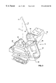
- FIG. 1 is an exploded perspective view of the stabilized platform system
- FIG. 2 is a perspective view of a stabilized platform system in accordance with one embodiment of the invention with some parts being omitted so as to show other parts more clearly,
- FIG. 3 is a perspective view of the universal joint arrangement used in the platform system shown in FIGS. 1 and 2,
- FIG. 4 is an exploded perspective view of the universal joint arrangement shown in FIG. 3,
- FIG. 5 is a perspective view of one of the magnetic torque motors used in the platform system
- FIG. 6 is a planned view of the torque motors and capacitive sensor array used in the platform system
- FIG. 7 is a perspective view of the torque motors and capacitive angle sensor array shown in FIG. 6 and
- FIG. 8 is a block diagram of the control system for the platform system.
- FIG. 1 shows a stabilized platform system with an outer gimbal in the form of a base assembly 12 securable to a supporting structure (not shown) such as a camera boom, an inner gimbal in the form of a payload stabilizing assembly 14 and a two-part casing 16 .
- the base assembly 12 has an octagonal base member 18 which is securable by bolts (not shown) to the supporting structure.
- the base member 18 carries the electrically energizable coil portions 20 of four torque motors substantially equally spaced around its periphery and extending in upwardly and outwardly inclined directions. Torque motors of this kind are described in more detail in previously mentioned U.S. Pat. No. 5,897,223.
- the base member 18 also carries diametrically opposite capacitive sensor arrays 22 of a pair of capacitive angle sensors located between adjacent pairs of motor coil portions 20 and also extending from the periphery of the base member 18 in upwardly and outwardly inclined directions. Capacitive angle sensors of this kind are also described in U.S. Pat. No. 5,897,223.
- the centre of the base member 18 has a circular stop portion 24 which limits motion of the payload stabilizing assembly 14 , as will be described in more detail later.
- the base member 18 further carries a mounting arm 26 for payload stabilizing assembly 14 which extends upwardly and outwardly from the periphery of the base member 18 and is located between adjacent pairs of motor coil portions 20 so that a pair of motor coil portions 20 with a capacitive sensor array 22 therebetween is located on each side of the mounting arm 26 .
- the payload stabilizing assembly 14 has a mounting arm 28 securable by bolts (not shown) to the mounting arm 26 of the base assembly 12 .
- a first angular adjustment arm 30 has one end pivotally mounted by means of a bearing 32 on the mounting arm 28 so that the adjustment arm 30 is capable of a limited amount of angular movement relative to the mounting arm 28 about an axis A which is upwardly and inwardly inclined in a manner which will be described in more detail later.
- a second angular adjustment arm 34 has one end pivotally mounted by means of a bearing 36 on the other end of the first adjustment arm 30 so that the adjustment arm 34 is capable of a limited amount of angular movement relative to the first adjustment arm 30 about an axis B of which is also upwardly and inwardly inclined in a manner which will be described in more detail later.
- a payload carrier 40 is pivotally mounted by means of a bearing 42 on the other end of the second adjustment arm 34 so that the payload carrier 40 is capable of a limited amount of angular movement relative to the second adjustment arm 34 about a vertical axis C.
- axes A, B and C meet at a point D which is some distance above the payload stabilizing assembly and which, when a payload is mounted thereon, is within the periphery of the payload (not shown).
- the orthogonal role, pitch and yaw axes x, y and z of the stabilizing assembly 14 meet at and pass through the point D at which extensions of axes A, B and C meet.
- a mounting plate 44 is secured in any suitable manner to the bottom of the payload carrier 40 and carries the motor and sensor components which complement the components provided on the base assembly 12 .
- the mounting plate 44 carries the magnetic structure portions 46 of the four torque motors substantially equally spaced around its periphery and angled to cooperate with the electrically energizable coil portions 20 mounted on the base assembly 12 .
- the mounting plate 44 also carries the capacitive excitation plates 48 of the two capacitive angle sensors located between adjacent pairs of magnetic structure portions 46 and angled to cooperate with the capacitive sensor arrays 22 on the base assembly 48 .
- the payload carrier 40 also carries an angular rate sensor, such as a fibre optic gyro (FOG) 50 , which is used in the same manner as described in U.S. Pat. No. 5,897,223.
- FOG fibre optic gyro
- the stabilizing assembly 14 also includes a payload interface plate 52 which is secured by bolts (not shown) to the top of the payload carrier 40 .
- An annular structural member 54 is secured by bolts (not shown) to the top of the mounting arm 28 of the stabilizing assembly 14 and also to the upper ends of mounting plates 21 , 23 on the base member 18 and on which motor coil portions 20 and the capacitive sensor arrays 22 are mounted, as well as to the upper end of mounting arm 26 .
- FIG. 4 shows a construction of the adjustment arm bearings 32 , 36 , 42 .
- Each bearing has a bearing shaft 60 , two bearing members 62 , a bearing cap 64 at the lower end, a retaining ring 66 at the upper end and a shaft retaining pin 68 .
- FIG. 5 shown one of the magnetic torque motors in more detail, namely the electrically energizable coil portion 20 which is carried by the base assembly 12 and the magnetic structure portion 46 which is carried by the stabilizing assembly 14 .
- the electrically energizable coil portion 20 which is carried by the base assembly 12
- the magnetic structure portion 46 which is carried by the stabilizing assembly 14 .
- FIG. 6 is a plan view of the four magnetic torque motors 20 , 46 and the two capacitive angle sensors 22 , 48 and their relation to the point of convergence D of the pivot axes A, B, and C shown in FIGS. 1 and 3.
- FIG. 7 is a perspective view of the same components from the same perspective as FIGS. 1 to 3 .
- FIG. 8 is a block diagram of the control system of the previously described embodiment of the invention.
- the control system is based on a single microprocessor and is generally similar to the control systems described in U.S. Pat. No. 5,897,223.
- the primary control algorithms of this microprocessor are shown as separate blocks in the figure.
- the angular rate sensor (or FOG) array 50 attached to the payload carrier 40 detects rates of rotation thereof relative to inertial coordinates.
- the processor's inner gimbal control algorithm computes and causes the torque motor array 20 to apply small correction moments to the inner gimbal using the principal of negative feedback to maintain the angular orientation of the payload stabilizing assembly in space.
- Capacitive angle sensors 22 sense the angular displacement between the base assembly 12 and the payload stabilizing assembly 14 about three orthogonal axes.
- the processor's outer gimbal control algorithm resolves the three angular displacements into components aligned with the axes of the outer follow-up devices servo axes. These displacements are then used to produce steering commands to drive a follow-up steering device to null each of the three angular displacements of the capacitive sensors 22 , i.e. to continually centre these sensors, in effect causing the follow-up steering device to follow the orientation of the payload stabilizing assembly 14 . Position feedback from the follow-up steering device may be used as part of the outer gimbal control algorithm when such information is available.
- these signals are resolved into three angular velocity vector components aligned with the angular rate sensing (or FOG) axes X, Y and Z, using the angles indicated by the capacitive angle sensor array and the position feedback from the follow-up steering device (if available) to determine the current orientation of the payload stabilizing assembly 14 .
- Three negative feedback control loops then drive the payload stabilizing assembly 14 to follow the external rate steering signals.
- the outer gimbal control algorithm causes the follow-up steering device to follow the moving payload stabilizing assembly 14 as before.
- Pitch and roll inclinometers mounted on the payload stabilizing assembly 14 may be used to generate automatic rate steering signals to steer the payload stabilizing assembly 14 to maintain a level horizon in the camera image.
- An alternative steering mode may us the three angular displacements measured by the capacitive sensors 22 to generate the three steering commands 70 to steer the payload stabilizing assembly 14 to null each of these displacements of the capacitive sensors 22 , i.e. to continually centre these sensors, in effect causing the payload stabilizing assembly 14 to follow the orientation of the supporting structure.
- the stabilized platform functions as a low pass filter between the payload and the supporting structure.
- Such a steering mode may be used with a tripod and a manually steered head.
- one adjustment arm may be omitted so that there are only two rotational axes.
- a further adjustment arm may be provided so that there are four rotational axes.
Abstract
Description
Claims (7)
Priority Applications (3)
| Application Number | Priority Date | Filing Date | Title |
|---|---|---|---|
| US09/330,043 US6263160B1 (en) | 1999-06-11 | 1999-06-11 | Stabilized platform systems for payloads |
| GB0013792A GB2350897B (en) | 1999-06-11 | 2000-06-06 | Stabilized platform systems for payloads |
| JP2000175754A JP4716392B2 (en) | 1999-06-11 | 2000-06-12 | Payload stabilized platform equipment |
Applications Claiming Priority (1)
| Application Number | Priority Date | Filing Date | Title |
|---|---|---|---|
| US09/330,043 US6263160B1 (en) | 1999-06-11 | 1999-06-11 | Stabilized platform systems for payloads |
Publications (1)
| Publication Number | Publication Date |
|---|---|
| US6263160B1 true US6263160B1 (en) | 2001-07-17 |
Family
ID=23288071
Family Applications (1)
| Application Number | Title | Priority Date | Filing Date |
|---|---|---|---|
| US09/330,043 Expired - Lifetime US6263160B1 (en) | 1999-06-11 | 1999-06-11 | Stabilized platform systems for payloads |
Country Status (3)
| Country | Link |
|---|---|
| US (1) | US6263160B1 (en) |
| JP (1) | JP4716392B2 (en) |
| GB (1) | GB2350897B (en) |
Cited By (29)
| Publication number | Priority date | Publication date | Assignee | Title |
|---|---|---|---|---|
| WO2002088585A2 (en) * | 2001-04-27 | 2002-11-07 | Engineered Support Systems, Inc. | Isolation platform assembly for supporting an instrumentation payload |
| US6611662B1 (en) * | 1999-05-28 | 2003-08-26 | David E. Grober | Autonomous, self leveling, self correcting stabilized platform |
| US6663298B2 (en) | 2002-02-07 | 2003-12-16 | Todd Gregory Haney | Hand held counter balance and shock absorber camera mount |
| US6718130B2 (en) * | 1999-05-28 | 2004-04-06 | David E. Grober | Stabilized camera and marker buoy for media coverage of aquatic events |
| US6849980B1 (en) * | 2003-02-21 | 2005-02-01 | Che Ram Souza Voigt | Cross plane wide-gap motor system for gimbal |
| US20060018646A1 (en) * | 2004-07-21 | 2006-01-26 | Stavely Donald J | Method of compensating for an effect of temperature on a control system |
| US20060017815A1 (en) * | 2004-07-21 | 2006-01-26 | Stavely Donald J | Flexible suspension for image stabilization |
| US20060018644A1 (en) * | 2004-07-21 | 2006-01-26 | Stavely Donald J | Apparatus and method for heat sinking a sensor |
| US20060021498A1 (en) * | 2003-12-17 | 2006-02-02 | Stanley Moroz | Optical muzzle blast detection and counterfire targeting system and method |
| US20070050139A1 (en) * | 2005-04-27 | 2007-03-01 | Sidman Adam D | Handheld platform stabilization system employing distributed rotation sensors |
| US20070108712A1 (en) * | 2005-08-23 | 2007-05-17 | Jeff Ryan | Shock isolation cradle |
| US20100079101A1 (en) * | 2005-04-27 | 2010-04-01 | Sidman Adam D | Handheld or vehicle-mounted platform stabilization system |
| US20100202766A1 (en) * | 2008-07-24 | 2010-08-12 | Teruyuki Takizawa | Camera driver |
| US20110164870A1 (en) * | 2008-06-07 | 2011-07-07 | Ei-Electronic Ideas Limited | Levelling apparatus |
| US8333520B1 (en) | 2011-03-24 | 2012-12-18 | CamMate Systems, Inc. | Systems and methods for detecting an imbalance of a camera crane |
| US20130181086A1 (en) * | 2012-01-15 | 2013-07-18 | Raytheon Company | Mitigation of drift effects in secondary inertial measurements of an isolated detector assembly |
| US8540438B1 (en) | 2011-03-24 | 2013-09-24 | CamMate Systems. Inc. | Systems and methods for positioning a camera crane |
| US20140225768A1 (en) * | 2013-02-12 | 2014-08-14 | Panasonic Avionics Corporation | Optimization of Low Profile Antenna(s) for Equatorial Operation |
| CN104406587A (en) * | 2014-11-06 | 2015-03-11 | 北京航空航天大学 | Protection type stabilized platform frame limiting device |
| DE102013015610A1 (en) * | 2013-09-19 | 2015-03-19 | Bundesrepublik Deutschland, vertreten durch das Bundesministerium der Verteidigung, vertreten durch das Bundesamt für Ausrüstung, Informationstechnik und Nutzung der Bundeswehr | Actuator for vibration decoupling |
| CN104508346A (en) * | 2013-12-10 | 2015-04-08 | 深圳市大疆创新科技有限公司 | Carrier of non-orthogonal shafts |
| WO2015095951A1 (en) | 2013-12-24 | 2015-07-02 | Pv Labs Inc. | Platform stabilization system |
| WO2017041302A1 (en) * | 2015-09-11 | 2017-03-16 | SZ DJI Technology Co., Ltd. | Stabilizing platform |
| US20170094185A1 (en) * | 2014-04-04 | 2017-03-30 | SZ DJI Technology Co., Ltd. | Gimbal driving device and gimbal assembly using the same |
| US20220002128A1 (en) * | 2020-04-09 | 2022-01-06 | Chapman/Leonard Studio Equipment, Inc. | Telescoping electric camera crane |
| US11225260B2 (en) * | 2017-03-28 | 2022-01-18 | Beijing Jingdong Qianshi Technology Co., Ltd. | Control method and device for automated guided vehicle, and automated guided vehicle |
| US11319985B2 (en) | 2020-08-03 | 2022-05-03 | Raytheon Company | Isolation joint with spherical bearing and integral angle measurement |
| US11560920B2 (en) * | 2015-07-02 | 2023-01-24 | Sz Dji Osmo Technology Co., Ltd. | Gimbal for image capturing |
| US20230066026A1 (en) * | 2020-02-17 | 2023-03-02 | Anton Yanovich RADZEVICH | Device for stabilizing video equipment |
Families Citing this family (1)
| Publication number | Priority date | Publication date | Assignee | Title |
|---|---|---|---|---|
| CN102420975A (en) * | 2011-11-01 | 2012-04-18 | 上海海事大学 | Anti-swaying device and method of sea-wrecking searching system |
Citations (3)
| Publication number | Priority date | Publication date | Assignee | Title |
|---|---|---|---|---|
| US4197548A (en) * | 1976-06-01 | 1980-04-08 | B. E. Industries, Inc. | Antenna stabilization system |
| US4919382A (en) * | 1988-09-14 | 1990-04-24 | The United States Of America As Represented By The Secretary Of The Navy | Multi-post yoke gimbal |
| US5638303A (en) * | 1995-06-28 | 1997-06-10 | Mcdonnell Douglas Corporation | Non-contacting isolated stabilized microgravity platform system |
Family Cites Families (8)
| Publication number | Priority date | Publication date | Assignee | Title |
|---|---|---|---|---|
| GB723951A (en) * | 1952-10-21 | 1955-02-16 | Ferranti Ltd | Improvements relating to stabilizing equipment |
| GB1230846A (en) * | 1968-09-26 | 1971-05-05 | ||
| US4498038A (en) * | 1983-02-15 | 1985-02-05 | Malueg Richard M | Stabilization system for soft-mounted platform |
| GB2173347A (en) * | 1985-02-15 | 1986-10-08 | Techwest A Division Of Fleet A | Stabilized mount for a platform |
| JPH02205494A (en) * | 1989-02-03 | 1990-08-15 | Hitachi Ltd | Method and device following image of manipulator and manipulator device equipped with the same device |
| JPH0678182A (en) * | 1992-08-26 | 1994-03-18 | Japan Aviation Electron Ind Ltd | Stabilized universal head servo loop circuit |
| JPH0965057A (en) * | 1995-06-14 | 1997-03-07 | Canon Inc | Image input device |
| US5897223A (en) * | 1997-11-17 | 1999-04-27 | Wescam Inc. | Stabilized platform system for camera |
-
1999
- 1999-06-11 US US09/330,043 patent/US6263160B1/en not_active Expired - Lifetime
-
2000
- 2000-06-06 GB GB0013792A patent/GB2350897B/en not_active Expired - Fee Related
- 2000-06-12 JP JP2000175754A patent/JP4716392B2/en not_active Expired - Fee Related
Patent Citations (3)
| Publication number | Priority date | Publication date | Assignee | Title |
|---|---|---|---|---|
| US4197548A (en) * | 1976-06-01 | 1980-04-08 | B. E. Industries, Inc. | Antenna stabilization system |
| US4919382A (en) * | 1988-09-14 | 1990-04-24 | The United States Of America As Represented By The Secretary Of The Navy | Multi-post yoke gimbal |
| US5638303A (en) * | 1995-06-28 | 1997-06-10 | Mcdonnell Douglas Corporation | Non-contacting isolated stabilized microgravity platform system |
Cited By (59)
| Publication number | Priority date | Publication date | Assignee | Title |
|---|---|---|---|---|
| US6611662B1 (en) * | 1999-05-28 | 2003-08-26 | David E. Grober | Autonomous, self leveling, self correcting stabilized platform |
| US6718130B2 (en) * | 1999-05-28 | 2004-04-06 | David E. Grober | Stabilized camera and marker buoy for media coverage of aquatic events |
| EP1423638A4 (en) * | 2001-04-27 | 2006-02-08 | Engineered Support Systems Inc | Isolation platform assembly for supporting an instrumentation payload |
| US6547205B2 (en) * | 2001-04-27 | 2003-04-15 | Engineered Support Systems, Inc. | Isolation platform assembly for supporting an instrumentation payload |
| WO2002088585A3 (en) * | 2001-04-27 | 2004-03-11 | Engineered Support Systems Inc | Isolation platform assembly for supporting an instrumentation payload |
| EP1423638A2 (en) * | 2001-04-27 | 2004-06-02 | Engineered Support Systems, Inc. | Isolation platform assembly for supporting an instrumentation payload |
| WO2002088585A2 (en) * | 2001-04-27 | 2002-11-07 | Engineered Support Systems, Inc. | Isolation platform assembly for supporting an instrumentation payload |
| US6663298B2 (en) | 2002-02-07 | 2003-12-16 | Todd Gregory Haney | Hand held counter balance and shock absorber camera mount |
| US6849980B1 (en) * | 2003-02-21 | 2005-02-01 | Che Ram Souza Voigt | Cross plane wide-gap motor system for gimbal |
| US20050225189A1 (en) * | 2003-02-21 | 2005-10-13 | Voigt Che R S | Cross plane wide-gap motor system for gimbal |
| US7190097B2 (en) * | 2003-02-21 | 2007-03-13 | Che Ram Souza Voigt | Cross plane wide-gap motor system for gimbal |
| US20060021498A1 (en) * | 2003-12-17 | 2006-02-02 | Stanley Moroz | Optical muzzle blast detection and counterfire targeting system and method |
| US7710460B2 (en) | 2004-07-21 | 2010-05-04 | Hewlett-Packard Development Company, L.P. | Method of compensating for an effect of temperature on a control system |
| US20060017815A1 (en) * | 2004-07-21 | 2006-01-26 | Stavely Donald J | Flexible suspension for image stabilization |
| US7679647B2 (en) * | 2004-07-21 | 2010-03-16 | Hewlett-Packard Development Company, L.P. | Flexible suspension for image stabilization |
| US20060018646A1 (en) * | 2004-07-21 | 2006-01-26 | Stavely Donald J | Method of compensating for an effect of temperature on a control system |
| US20060018644A1 (en) * | 2004-07-21 | 2006-01-26 | Stavely Donald J | Apparatus and method for heat sinking a sensor |
| US8179078B2 (en) | 2005-04-27 | 2012-05-15 | Sidman Adam D | Handheld or vehicle-mounted platform stabilization system |
| US20070050139A1 (en) * | 2005-04-27 | 2007-03-01 | Sidman Adam D | Handheld platform stabilization system employing distributed rotation sensors |
| US20100079101A1 (en) * | 2005-04-27 | 2010-04-01 | Sidman Adam D | Handheld or vehicle-mounted platform stabilization system |
| US7642741B2 (en) | 2005-04-27 | 2010-01-05 | Sidman Adam D | Handheld platform stabilization system employing distributed rotation sensors |
| US20070108712A1 (en) * | 2005-08-23 | 2007-05-17 | Jeff Ryan | Shock isolation cradle |
| US7513516B2 (en) | 2005-08-23 | 2009-04-07 | Jri Development Group, Llc | Shock isolation cradle |
| US20110164870A1 (en) * | 2008-06-07 | 2011-07-07 | Ei-Electronic Ideas Limited | Levelling apparatus |
| US8408820B2 (en) * | 2008-06-07 | 2013-04-02 | Ei-Electronic Ideas Limited | Levelling apparatus |
| US20100202766A1 (en) * | 2008-07-24 | 2010-08-12 | Teruyuki Takizawa | Camera driver |
| US8027579B2 (en) * | 2008-07-24 | 2011-09-27 | Panasonic Corporation | Camera driver |
| US8540438B1 (en) | 2011-03-24 | 2013-09-24 | CamMate Systems. Inc. | Systems and methods for positioning a camera crane |
| US8333520B1 (en) | 2011-03-24 | 2012-12-18 | CamMate Systems, Inc. | Systems and methods for detecting an imbalance of a camera crane |
| US8552350B2 (en) * | 2012-01-15 | 2013-10-08 | Raytheon Company | Mitigation of drift effects in secondary inertial measurements of an isolated detector assembly |
| US20130181086A1 (en) * | 2012-01-15 | 2013-07-18 | Raytheon Company | Mitigation of drift effects in secondary inertial measurements of an isolated detector assembly |
| US9583829B2 (en) * | 2013-02-12 | 2017-02-28 | Panasonic Avionics Corporation | Optimization of low profile antenna(s) for equatorial operation |
| US20140225768A1 (en) * | 2013-02-12 | 2014-08-14 | Panasonic Avionics Corporation | Optimization of Low Profile Antenna(s) for Equatorial Operation |
| DE102013015610A1 (en) * | 2013-09-19 | 2015-03-19 | Bundesrepublik Deutschland, vertreten durch das Bundesministerium der Verteidigung, vertreten durch das Bundesamt für Ausrüstung, Informationstechnik und Nutzung der Bundeswehr | Actuator for vibration decoupling |
| US9789976B2 (en) * | 2013-12-10 | 2017-10-17 | Sz Dji Osmo Technology Co., Ltd. | Carrier having non-orthogonal axes |
| CN104508346A (en) * | 2013-12-10 | 2015-04-08 | 深圳市大疆创新科技有限公司 | Carrier of non-orthogonal shafts |
| WO2015085499A1 (en) * | 2013-12-10 | 2015-06-18 | 深圳市大疆创新科技有限公司 | Non-orthogonal axis carrier |
| US20170106998A1 (en) * | 2013-12-10 | 2017-04-20 | SZ DJI Technology Co., Ltd. | Carrier having non-orthogonal axes |
| US20160229556A1 (en) * | 2013-12-10 | 2016-08-11 | SZ DJI Technology Co., Ltd. | Carrier having non-orthogonal axes |
| CN104508346B (en) * | 2013-12-10 | 2016-09-28 | 深圳市大疆创新科技有限公司 | Non-orthogonal axes carrier |
| US9561870B2 (en) * | 2013-12-10 | 2017-02-07 | SZ DJI Technology Co., Ltd. | Carrier having non-orthogonal axes |
| US9765925B2 (en) | 2013-12-24 | 2017-09-19 | Pv Labs Ltd. | Platform stabilization system |
| AU2014373639B2 (en) * | 2013-12-24 | 2017-11-16 | Pv Labs Ltd. | Platform stabilization system |
| JP2017508109A (en) * | 2013-12-24 | 2017-03-23 | ピーブイ ラボズ インク.Pv Labs Inc. | Platform stabilization system |
| US9348197B2 (en) | 2013-12-24 | 2016-05-24 | Pv Labs Inc. | Platform stabilization system |
| WO2015095951A1 (en) | 2013-12-24 | 2015-07-02 | Pv Labs Inc. | Platform stabilization system |
| US20170094185A1 (en) * | 2014-04-04 | 2017-03-30 | SZ DJI Technology Co., Ltd. | Gimbal driving device and gimbal assembly using the same |
| US9749544B2 (en) * | 2014-04-04 | 2017-08-29 | Sz Dji Osmo Technology Co., Ltd. | Gimbal driving device and gimbal assembly using the same |
| CN104406587B (en) * | 2014-11-06 | 2017-09-05 | 北京航空航天大学 | A kind of protection formula stabilized platform framework stopping means |
| CN104406587A (en) * | 2014-11-06 | 2015-03-11 | 北京航空航天大学 | Protection type stabilized platform frame limiting device |
| US11560920B2 (en) * | 2015-07-02 | 2023-01-24 | Sz Dji Osmo Technology Co., Ltd. | Gimbal for image capturing |
| WO2017041302A1 (en) * | 2015-09-11 | 2017-03-16 | SZ DJI Technology Co., Ltd. | Stabilizing platform |
| CN108137166A (en) * | 2015-09-11 | 2018-06-08 | 深圳市大疆灵眸科技有限公司 | Stability augmentation platform |
| US10766635B2 (en) | 2015-09-11 | 2020-09-08 | Sz Dji Osmo Technology Co., Ltd. | Stabilizing platform |
| CN108137166B (en) * | 2015-09-11 | 2020-11-20 | 深圳市大疆灵眸科技有限公司 | Stability augmentation platform |
| US11225260B2 (en) * | 2017-03-28 | 2022-01-18 | Beijing Jingdong Qianshi Technology Co., Ltd. | Control method and device for automated guided vehicle, and automated guided vehicle |
| US20230066026A1 (en) * | 2020-02-17 | 2023-03-02 | Anton Yanovich RADZEVICH | Device for stabilizing video equipment |
| US20220002128A1 (en) * | 2020-04-09 | 2022-01-06 | Chapman/Leonard Studio Equipment, Inc. | Telescoping electric camera crane |
| US11319985B2 (en) | 2020-08-03 | 2022-05-03 | Raytheon Company | Isolation joint with spherical bearing and integral angle measurement |
Also Published As
| Publication number | Publication date |
|---|---|
| GB0013792D0 (en) | 2000-07-26 |
| GB2350897A (en) | 2000-12-13 |
| JP4716392B2 (en) | 2011-07-06 |
| JP2001041395A (en) | 2001-02-13 |
| GB2350897B (en) | 2003-01-22 |
Similar Documents
| Publication | Publication Date | Title |
|---|---|---|
| US6263160B1 (en) | Stabilized platform systems for payloads | |
| US4989466A (en) | Gyroscopically stabilized sensor positioning system | |
| US5897223A (en) | Stabilized platform system for camera | |
| US4828376A (en) | Triaxis stabilized platform | |
| US7894144B2 (en) | High accuracy optical pointing apparatus | |
| US6154317A (en) | Device for stabilizing of a remotely controlled sensor, like a camera | |
| EP0128935A1 (en) | Improved suspension system for supporting and conveying equipment, such as a camera | |
| EP3542414B1 (en) | A stabilization arrangement for stabilization of an antenna mast | |
| US4315610A (en) | Optical image stabilizing system | |
| KR20180099650A (en) | Active stabilization system | |
| US6789437B2 (en) | Apparatus for precision slewing of flatform-mounted devices | |
| JPH10104673A (en) | Image stabilizer | |
| CA2275015C (en) | Stabilized platform systems for payloads | |
| KR20190069801A (en) | Device of driving camera, driving method thereof and jimbal apparatus | |
| JP3441898B2 (en) | Image stabilizer | |
| JP2002277245A (en) | Space stabilizer | |
| JPS607202A (en) | Stabilizer | |
| JPS62184376A (en) | Antenna directing device | |
| JPS6271307A (en) | Antenna stabilizer | |
| KR20190143172A (en) | Pan-tilt-gimbal integrated system and control method thereof | |
| JP3203855B2 (en) | Optical device | |
| JPS5934161Y2 (en) | stabilizer device | |
| JPH07154128A (en) | Antenna directing device | |
| KR20230121344A (en) | Drive module for axis-free inertial stabilization platform | |
| JPH02177773A (en) | Stabilizer for video camera |
Legal Events
| Date | Code | Title | Description |
|---|---|---|---|
| AS | Assignment |
Owner name: WESCAM INC., CANADA Free format text: ASSIGNMENT OF ASSIGNORS INTEREST;ASSIGNOR:LEWIS, MICHAEL D.;REEL/FRAME:010184/0354 Effective date: 19990811 |
|
| STCF | Information on status: patent grant |
Free format text: PATENTED CASE |
|
| FPAY | Fee payment |
Year of fee payment: 4 |
|
| AS | Assignment |
Owner name: PICTORVISION INCORPORATED, CANADA Free format text: ASSIGNMENT OF ASSIGNORS INTEREST;ASSIGNOR:WESCAM INC.;REEL/FRAME:017957/0391 Effective date: 20060508 |
|
| AS | Assignment |
Owner name: PV LABS INC., CANADA Free format text: ARTICLES OF AMALGAMATION;ASSIGNOR:PICTORVISION INCORPORATED;REEL/FRAME:020741/0760 Effective date: 20071206 |
|
| FPAY | Fee payment |
Year of fee payment: 8 |
|
| FPAY | Fee payment |
Year of fee payment: 12 |
|
| AS | Assignment |
Owner name: BDC CAPITAL INC., A WHOLLY-OWNED SUBSIDIARY OF BUS Free format text: SECURITY INTEREST;ASSIGNOR:PV LABS INC.;REEL/FRAME:035670/0001 Effective date: 20110425 |
|
| AS | Assignment |
Owner name: PV LABS LTD., CANADA Free format text: NUNC PRO TUNC ASSIGNMENT;ASSIGNORS:902878 ONTARIO LIMITED;PV LABS INC.;REEL/FRAME:045252/0219 Effective date: 20171218 |