US6268564B1 - Connector fixing construction of connector bracket - Google Patents
Connector fixing construction of connector bracket Download PDFInfo
- Publication number
- US6268564B1 US6268564B1 US09/271,207 US27120799A US6268564B1 US 6268564 B1 US6268564 B1 US 6268564B1 US 27120799 A US27120799 A US 27120799A US 6268564 B1 US6268564 B1 US 6268564B1
- Authority
- US
- United States
- Prior art keywords
- connector
- fitting grooves
- partition walls
- bracket
- connector bracket
- Prior art date
- Legal status (The legal status is an assumption and is not a legal conclusion. Google has not performed a legal analysis and makes no representation as to the accuracy of the status listed.)
- Expired - Fee Related
Links
Images

Classifications
-
- H—ELECTRICITY
- H01—ELECTRIC ELEMENTS
- H01R—ELECTRICALLY-CONDUCTIVE CONNECTIONS; STRUCTURAL ASSOCIATIONS OF A PLURALITY OF MUTUALLY-INSULATED ELECTRICAL CONNECTING ELEMENTS; COUPLING DEVICES; CURRENT COLLECTORS
- H01R13/00—Details of coupling devices of the kinds covered by groups H01R12/70 or H01R24/00 - H01R33/00
- H01R13/46—Bases; Cases
- H01R13/516—Means for holding or embracing insulating body, e.g. casing, hoods
- H01R13/518—Means for holding or embracing insulating body, e.g. casing, hoods for holding or embracing several coupling parts, e.g. frames
Landscapes
- Details Of Connecting Devices For Male And Female Coupling (AREA)
- Connector Housings Or Holding Contact Members (AREA)
Abstract
In a connector fixing construction of a connector bracket, there are provided a plurality of kinds of partition walls which can be suitably fixed within the connector bracket. A plurality of first fitting grooves for receiving and holding the various partition walls are formed in an inner peripheral surface of the connector bracket. A first lock projection is provided in the first fitting groove, and a second lock projection for engagement with the first lock projection is formed on each of opposite end surfaces of the partition wall. A connector lock for holding the connector is formed on each of the partition walls at a lower end portion thereof. A plurality of second fitting grooves are formed in each of opposite sides of the partition walls.
Description
1. Field of the Invention
This invention relates to a connector fixing construction of a connector bracket, and more particularly to a connector fixing construction of a connector bracket, in which a plurality of kinds of partition walls are held within a bracket so that various connectors can be fixed within the bracket.
2. Description of the Related Art
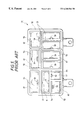
Various connector fixing constructions of a connector bracket are already known. For example, there is known a connector fixing construction 51 of a connector bracket shown in FIGS. 5 and 6. The conventional connector bracket 52, shown in FIG. 5, includes partition walls 53 defining connector receiving chambers 54 to 58 for respectively receiving many kinds of connectors 61 to 65, and connector locks 59 provided adjacent respectively to the bottoms of the connector receiving chambers 54 to 58 for holding the connectors 61 to 65, respectively.
In the above connector fixing construction 51 of the connector bracket, when five kinds of connectors 61 to 65 are fitted respectively into the connector receiving chambers 54 to 58 from the bottom side of the connector bracket 52, these connectors are locked by the connector locks 59, respectively.
Thus, in the conventional connector fixing construction 51 of the connector bracket, many kinds of connectors 61 to 65 can be received and held within the connector bracket 52, and therefore the overall construction can be made compact as compared with the case where the connectors are mounted separately.
There is no problem with the above conventional connector fixing construction 51 of the connector bracket if the kinds and number of connectors to be received and held within the connector bracket are fixed. However, in many cases, the kinds and number of connectors are changed when the specification is changed or when the connector bracket is used in another kind of car. Therefore, the conventional connector bracket 52, in which the connector receiving chambers 54 to 58 are formed by the fixed partition walls 53, could not deal with such change, and therefore is inferior in versatility.
With the above problem in view, it is an object of this invention to provide a connector fixing construction of a connector bracket in which even if the kinds and number of connectors to be used are changed, this change can be dealt with.
In order to achieve the above object, according to the present invention, there is provided a connector fixing construction comprising: a connector bracket having a plurality of first fitting grooves formed in an inner peripheral surface thereof, the first fitting grooves extending vertically; and a plurality of kinds of partition walls for being fitted and held in the fitting grooves, wherein each of the partition walls is fitted in desired opposed ones of the first fitting grooves so that a plurality of connectors are fixed in their respective predetermined positions within the connector bracket.
In the above connector fixing construction of the connector bracket, the plurality of first fitting grooves are formed in the inner peripheral surface of the connector bracket, and extend vertically, and there are provided the plurality of kinds of partition walls for being fitted and held in the fitting grooves; and each of the partition walls is fitted in the desired opposed first fitting grooves so that the plurality of connectors can be fixed in their respective predetermined positions within the connector bracket. Therefore, even if the kinds and number of connectors to be used are changed, connector receiving chambers for respectively receiving the connectors can be formed. Therefore, there can be obtained the connector bracket having excellent versatility.
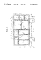
FIG. 1 is a plan view of a preferred embodiment of a connector fixing construction of a connector bracket of the invention;
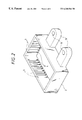
FIG. 2 is a perspective view of the connector bracket in FIG. 1;
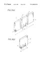
FIGS. 3(a) and 3(b) are perspective views showing partition walls in FIG. 1;
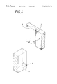
FIG. 4 is a perspective view showing a first lock projection and a second lock projection in FIG. 1;
FIG. 5 is a plan view showing a conventional connector fixing construction of a connector bracket; and
FIG. 6 is a side-elevational view of the connector bracket in FIG. 5.
A preferred embodiment of a connector fixing construction of a connector bracket of the invention will now be described in detail with reference to FIGS. 1 to 4. FIG. 1 is a plan view of the preferred embodiment of the connector fixing construction of the connector bracket of the invention, FIG. 2 is a perspective view of the connector bracket in FIG. 1, FIGS. 3(a) and 3(b) are perspective views showing partition walls in FIG. 1, and FIG. 4 is a perspective view showing a first fitting groove and an end surface of the partition wall in FIG. 1.
As shown in FIGS. 1 to 3(b), the connector bracket 2, having the connector fixing construction 1, is made, for example, of a synthetic resin, and connectors 21, 22, 23 and 24 are received and fixed within the connector bracket 2. A plurality of first fitting grooves 3 are formed in an inner peripheral surface of the connector bracket 2, and extend vertically (that is, in the direction of the height thereof). A plurality of kinds of partition walls (described later) can be fitted at their ends in the first fitting grooves 3. A first lock projection 4 for retaining the partition wall is formed at a lower end portion of each first fitting groove 3 (see FIG. 2).
There are provided the plurality of kinds of partition walls of different widths L, that is, the large-size partition walls 5, the medium- size partition walls 15, 16 and 17, and the small-size partition walls 8 (see FIGS. 3(a) and 3(b)). These partition walls can be suitably mounted within the connector bracket 2. A second lock projection 6 for engagement with the first lock projection 4 is formed on a lower end portion of each of opposite side end surfaces of each of the partition walls.
A connector lock 7 for holding the connectors 21, 22, 23, 24 is formed at a lower end portion of each of the partition walls 5, 8, 15, 16 and 17, and is disposed centrally of the length thereof. Slits 7 a are formed in the partition wall, and are disposed respectively on opposite sides of the connector lock 7 so that that portion of the partition wall, having the connector lock 7, can be easily elastically deformed.
As shown in FIGS. 2, 3(a) and 3(b), the upper ends of the first and second fitting grooves 3 and 9 are not open upwardly, but are closed. Mounting brackets 18 each having a mounting hole 19 are formed integrally on the connector bracket 2, and the connector bracket 2 can be easily mounted on a vehicle body or the like through these mounting brackets 18.
In the above connector fixing construction 1 of the connector bracket, each partition wall 5 is first fitted into the desired first fitting grooves 3 from the lower side of the connector bracket 2, so that the second lock projections 6 are retainingly engaged respectively with the corresponding first lock projections 4, thereby fixing the partition wall 5 to the connector bracket 2. Then, the partition wall 17 is fitted in the second fitting grooves 9 in the partition walls 5 as shown in FIG. 1, so that the partition wall 17 is held on the partition walls 5 since the second fitting grooves 9 have the closed upper and lower ends. As a result, there is formed a connector receiving chamber 13 for receiving the large-size connector 23.
When each partition wall 8 is held in the desired first and second fitting grooves 3 and 9, there are formed connector receiving chambers 14 for receiving the small-size connectors 24, respectively. Further, when the partition walls 8, 15 and 16 are held in the desired first and second fitting grooves 3 and 9, connector receiving chambers 11 for respectively receiving the medium-size connectors 21, as well as connector receiving chambers 12 for respectively receiving the medium-size connectors 22, are formed. Then, the various connectors 21 to 24 are inserted respectively into the connector receiving chambers 11 to 14 from the lower side of the connector bracket 2, and are held by the connector locks 7.
As described above, in the connector fixing construction of the connector bracket of this embodiment, there are provided the plurality of kinds of partition walls 5, 8, 15, 16 and 17 which can be suitably mounted within the connector bracket 2, and the plurality of first fitting grooves 3, capable of holding the partition walls, are formed in the inner peripheral surface of the connector bracket 2. The second fitting grooves 9 for enabling the interior of the connector bracket to be divided into many sections are formed in the opposite sides (faces) of the partition walls 5, 15, 16 and 17.
Therefore, there can be formed the connector receiving chambers 11 to 14 corresponding to the various connectors 21 to 24 of difference shapes. Therefore, there can be obtained the connector bracket having excellent versatility.
The first lock projection 4 is formed in each first fitting groove 3, and the second lock projections 6 are formed on each partition wall 5, 8, 15, 16, 17, and the connector lock 7 for holding the connector 21, 22, 23, 24 is formed on the partition wall 5, 8, 15, 16 and 17 at its lower end portion. Therefore, the various partition walls 5, 8, 15, 16 and 17 and the various connectors 21 to 24 can be positively fixed within the connector bracket 2, and there can be obtained the connector bracket 2 of high reliability.
The connector fixing construction of the connector bracket of the invention is not limited to the above embodiment, but various modifications can be made. For example, in the above embodiment, although one connector lock 7 is formed on the central portion of the lower end portion of each partition wall, the connector lock 7 does not always need to be provided at the central portion, and also a plurality of connector locks may be provided in the case of using a large-size connector.
As described above, in the connector fixing construction of the connector bracket of the present invention, the plurality of first fitting grooves are formed in the inner peripheral surface of the connector bracket, and extend vertically, and there are provided the plurality of kinds of partition walls for being fitted and held in the fitting grooves, and each of the partition walls is fitted in the desired opposed first fitting grooves so that the plurality of connectors can be fixed in their respective predetermined positions within the connector bracket.
Therefore, even if the kinds and number of connectors to be used are changed, the connector receiving chambers for respectively receiving the connectors can be formed. Therefore, there can be obtained the connector bracket having excellent versatility.
The plurality of second fitting grooves for enabling the interior of the connector bracket to be divided into many sections are formed in each of the opposite sides of the partition wall, the second fitting grooves extending vertically. The first lock projection is provided in the first fitting groove, and the second lock projection for engagement with the first lock projection is formed on each of the opposite end surfaces of the partition wall.
Therefore, even if the kinds and number of connectors to be used are changed in a wider range, the connector receiving chambers for respectively receiving the connectors can be formed, and the partition walls and the connectors can be positively held. Therefore, there can be obtained the connector bracket having more excellent versatility and high reliability.
Claims (2)
1. A connector fixing structure comprising:
a connector bracket having a plurality of first fitting grooves formed in an inner peripheral surface thereof, said first fitting grooves extending vertically; and
a plurality of kinds of partition walls for being fitted and held in said first fitting grooves,
wherein each of said partition walls is fitted in desired opposed ones of said first fitting grooves so that a plurality of connectors are fixed in their respective predetermined positions within said connector bracket; and
a plurality of second fitting grooves for enabling an interior of said connector bracket to be divided into many sections are formed in each of opposite side surfaces of each of said partition walls, said second fitting grooves extending vertically and each having closed upper and lower ends.
2. A connector fixing structure comprising:
a connector bracket having a plurality of first fitting grooves formed in an inner peripheral surface thereof, said first fitting grooves extending vertically; and
a plurality of kinds of partition walls for being fitted and held in said first fitting grooves,
wherein each of said partition walls is fitted in desired opposed ones of said first fitting grooves so that a plurality of connectors are fixed in their respective predetermined positions within said connector bracket; and
wherein a first lock projection is formed in each of said first fitting grooves, and a second lock projection for engagement with said first lock projection is formed on each of opposite end surfaces of each of said partition walls.
Applications Claiming Priority (2)
| Application Number | Priority Date | Filing Date | Title |
|---|---|---|---|
| JP10-068639 | 1998-03-18 | ||
| JP10068639A JPH11265753A (en) | 1998-03-18 | 1998-03-18 | Connector fixing structure of connector bracket |
Publications (1)
| Publication Number | Publication Date |
|---|---|
| US6268564B1 true US6268564B1 (en) | 2001-07-31 |
Family
ID=13379513
Family Applications (1)
| Application Number | Title | Priority Date | Filing Date |
|---|---|---|---|
| US09/271,207 Expired - Fee Related US6268564B1 (en) | 1998-03-18 | 1999-03-17 | Connector fixing construction of connector bracket |
Country Status (2)
| Country | Link |
|---|---|
| US (1) | US6268564B1 (en) |
| JP (1) | JPH11265753A (en) |
Cited By (10)
| Publication number | Priority date | Publication date | Assignee | Title |
|---|---|---|---|---|
| US20040007486A1 (en) * | 2002-05-24 | 2004-01-15 | Bergh James A. | Adjustable partition device for portable containers |
| US20050032436A1 (en) * | 2003-08-07 | 2005-02-10 | Mancini Danna A. | Powerpole connector assembly and methods thereof |
| US20060169701A1 (en) * | 2005-02-01 | 2006-08-03 | Meissen Cynthia R | Storage container |
| US20070246471A1 (en) * | 2006-03-15 | 2007-10-25 | Heimo Hrovat | Module tray system |
| US7374460B1 (en) | 2007-04-17 | 2008-05-20 | Traxxas Lp | Electrical connector assembly |
| US8759674B2 (en) | 2012-05-29 | 2014-06-24 | Hubbell Incorporated | Electrical box with multi-directional partition plate |
| US10361548B2 (en) * | 2017-01-18 | 2019-07-23 | Siemens Schweiz Ag | Divided junction box |
| USD933014S1 (en) | 2020-03-16 | 2021-10-12 | Traxxas Lp | Electrical connector for a model vehicle |
| USD939442S1 (en) | 2020-03-16 | 2021-12-28 | Traxxas Lp | Electrical connector for a model vehicle |
| US11569589B2 (en) | 2020-04-07 | 2023-01-31 | Traxxas, L.P. | Electrical power tap connector |
Families Citing this family (1)
| Publication number | Priority date | Publication date | Assignee | Title |
|---|---|---|---|---|
| JP5705812B2 (en) * | 2012-11-15 | 2015-04-22 | 古河電気工業株式会社 | Connector holder |
Citations (11)
| Publication number | Priority date | Publication date | Assignee | Title |
|---|---|---|---|---|
| US2788912A (en) * | 1954-12-08 | 1957-04-16 | Simonsen Metal Products Compan | Tray |
| US4261465A (en) * | 1979-08-29 | 1981-04-14 | C. R. Daniels, Inc. | Tote box for carrying different length circuit boards |
| GB2134884A (en) * | 1982-12-23 | 1984-08-22 | Polstore | Drawer divider |
| US4577773A (en) * | 1984-08-10 | 1986-03-25 | The Rogers Manufacturing Co. | Utility box |
| WO1991017066A1 (en) * | 1990-05-04 | 1991-11-14 | Mark Wayne | Truck bed divider system |
| US5240301A (en) * | 1989-01-05 | 1993-08-31 | Arnold Richard E | Bed liner having integral cargo restraint capability |
| US5299688A (en) * | 1992-03-20 | 1994-04-05 | Pro Box | Storage device and system for card collections |
| US5441150A (en) * | 1992-09-03 | 1995-08-15 | Ma Laboratories, Inc. | Memory module container |
| US5584412A (en) * | 1996-05-01 | 1996-12-17 | Kuan Tong Industrial Co., Ltd. | Box disposed in a car trunk |
| US5594207A (en) * | 1993-06-02 | 1997-01-14 | Thomas & Betts Corporation | Self-locking divider plate for an electrical box |
| US5664856A (en) * | 1994-02-17 | 1997-09-09 | Snap-On Technologies, Inc. | Stackable divided drawer partition |
-
1998
- 1998-03-18 JP JP10068639A patent/JPH11265753A/en active Pending
-
1999
- 1999-03-17 US US09/271,207 patent/US6268564B1/en not_active Expired - Fee Related
Patent Citations (11)
| Publication number | Priority date | Publication date | Assignee | Title |
|---|---|---|---|---|
| US2788912A (en) * | 1954-12-08 | 1957-04-16 | Simonsen Metal Products Compan | Tray |
| US4261465A (en) * | 1979-08-29 | 1981-04-14 | C. R. Daniels, Inc. | Tote box for carrying different length circuit boards |
| GB2134884A (en) * | 1982-12-23 | 1984-08-22 | Polstore | Drawer divider |
| US4577773A (en) * | 1984-08-10 | 1986-03-25 | The Rogers Manufacturing Co. | Utility box |
| US5240301A (en) * | 1989-01-05 | 1993-08-31 | Arnold Richard E | Bed liner having integral cargo restraint capability |
| WO1991017066A1 (en) * | 1990-05-04 | 1991-11-14 | Mark Wayne | Truck bed divider system |
| US5299688A (en) * | 1992-03-20 | 1994-04-05 | Pro Box | Storage device and system for card collections |
| US5441150A (en) * | 1992-09-03 | 1995-08-15 | Ma Laboratories, Inc. | Memory module container |
| US5594207A (en) * | 1993-06-02 | 1997-01-14 | Thomas & Betts Corporation | Self-locking divider plate for an electrical box |
| US5664856A (en) * | 1994-02-17 | 1997-09-09 | Snap-On Technologies, Inc. | Stackable divided drawer partition |
| US5584412A (en) * | 1996-05-01 | 1996-12-17 | Kuan Tong Industrial Co., Ltd. | Box disposed in a car trunk |
Cited By (20)
| Publication number | Priority date | Publication date | Assignee | Title |
|---|---|---|---|---|
| US20040007486A1 (en) * | 2002-05-24 | 2004-01-15 | Bergh James A. | Adjustable partition device for portable containers |
| US20050032436A1 (en) * | 2003-08-07 | 2005-02-10 | Mancini Danna A. | Powerpole connector assembly and methods thereof |
| US7004795B2 (en) * | 2003-08-07 | 2006-02-28 | Anderson Power Products | Powerpole connector assembly and methods thereof |
| US20060169701A1 (en) * | 2005-02-01 | 2006-08-03 | Meissen Cynthia R | Storage container |
| US20070246471A1 (en) * | 2006-03-15 | 2007-10-25 | Heimo Hrovat | Module tray system |
| US20110076886A1 (en) * | 2007-04-17 | 2011-03-31 | Seralaathan Hariharesan | Electrical connector assembly |
| US10177500B2 (en) | 2007-04-17 | 2019-01-08 | Traxxas Lp | Electrical connector assembly |
| US7530855B2 (en) | 2007-04-17 | 2009-05-12 | Traxxas Lp | Electrical connector assembly |
| US20090186530A1 (en) * | 2007-04-17 | 2009-07-23 | Seralaathan Hariharesan | Electrical Connector Assembly |
| US7867038B2 (en) | 2007-04-17 | 2011-01-11 | Traxxas Lp | Electrical connector assembly |
| US7374460B1 (en) | 2007-04-17 | 2008-05-20 | Traxxas Lp | Electrical connector assembly |
| US8641440B2 (en) | 2007-04-17 | 2014-02-04 | Traxxas Lp | Electrical connector assembly |
| US20080261460A1 (en) * | 2007-04-17 | 2008-10-23 | Seralaathan Hariharesan | Electrical connector assembly |
| US9166323B2 (en) | 2007-04-17 | 2015-10-20 | Traxxas Lp | Electrical Connector Assembly |
| US9705254B2 (en) | 2007-04-17 | 2017-07-11 | Traxxas Lp | Electrical connector assembly |
| US8759674B2 (en) | 2012-05-29 | 2014-06-24 | Hubbell Incorporated | Electrical box with multi-directional partition plate |
| US10361548B2 (en) * | 2017-01-18 | 2019-07-23 | Siemens Schweiz Ag | Divided junction box |
| USD933014S1 (en) | 2020-03-16 | 2021-10-12 | Traxxas Lp | Electrical connector for a model vehicle |
| USD939442S1 (en) | 2020-03-16 | 2021-12-28 | Traxxas Lp | Electrical connector for a model vehicle |
| US11569589B2 (en) | 2020-04-07 | 2023-01-31 | Traxxas, L.P. | Electrical power tap connector |
Also Published As
| Publication number | Publication date |
|---|---|
| JPH11265753A (en) | 1999-09-28 |
Similar Documents
| Publication | Publication Date | Title |
|---|---|---|
| US6268564B1 (en) | Connector fixing construction of connector bracket | |
| JP3410951B2 (en) | Electrical junction box | |
| US7413463B2 (en) | Containing structure for circuit board | |
| US5575683A (en) | Connector with front piece fixing terminals | |
| KR100251116B1 (en) | Connector | |
| US5356302A (en) | Joint connector | |
| US6074234A (en) | Connector assembly with locking structures disposed in concave exterior corners | |
| EP1524729B1 (en) | Electrical connector | |
| JP3108072U (en) | Metal housing for airbag control device | |
| US5277623A (en) | Low profile panel mountable retainer for electrical connectors | |
| US5190477A (en) | Wire harness connection structure | |
| US6138843A (en) | Frame piece for a rack of a switching cabinet | |
| US5443392A (en) | Shielding device for rectangular cable plugs | |
| US5839907A (en) | Structure of card | |
| US20050026480A1 (en) | Ground joint connector | |
| US5236114A (en) | Carrier basket | |
| US6172299B1 (en) | Box-shaped electric part-mounting construction | |
| US5529338A (en) | One piece automotive airbag squib connector | |
| US6098826A (en) | Communications equipment housing | |
| JP2500645B2 (en) | Electronic component package mounting case | |
| EP0884804B1 (en) | Electrical connector housing | |
| JP4220179B2 (en) | PCB carrier case | |
| US7654852B2 (en) | Connector and connector assembling system | |
| EP0986144A1 (en) | Electrical connection box | |
| US20220045454A1 (en) | Connector Housing |
Legal Events
| Date | Code | Title | Description |
|---|---|---|---|
| AS | Assignment |
Owner name: YAZAKI CORPORATION, JAPAN Free format text: ASSIGNMENT OF ASSIGNORS INTEREST;ASSIGNOR:MIYAKOSHI, KOJI;REEL/FRAME:009835/0394 Effective date: 19990305 |
|
| FPAY | Fee payment |
Year of fee payment: 4 |
|
| REMI | Maintenance fee reminder mailed | ||
| LAPS | Lapse for failure to pay maintenance fees | ||
| STCH | Information on status: patent discontinuation |
Free format text: PATENT EXPIRED DUE TO NONPAYMENT OF MAINTENANCE FEES UNDER 37 CFR 1.362 |
|
| FP | Lapsed due to failure to pay maintenance fee |
Effective date: 20090731 |