US6269129B1 - 64/256 quadrature amplitude modulation trellis coded modulation decoder - Google Patents
64/256 quadrature amplitude modulation trellis coded modulation decoder Download PDFInfo
- Publication number
- US6269129B1 US6269129B1 US09/066,048 US6604898A US6269129B1 US 6269129 B1 US6269129 B1 US 6269129B1 US 6604898 A US6604898 A US 6604898A US 6269129 B1 US6269129 B1 US 6269129B1
- Authority
- US
- United States
- Prior art keywords
- bits
- uncoded
- phase
- quadrature
- decoder
- Prior art date
- Legal status (The legal status is an assumption and is not a legal conclusion. Google has not performed a legal analysis and makes no representation as to the accuracy of the status listed.)
- Expired - Lifetime
Links
Images


Classifications
-
- H—ELECTRICITY
- H04—ELECTRIC COMMUNICATION TECHNIQUE
- H04L—TRANSMISSION OF DIGITAL INFORMATION, e.g. TELEGRAPHIC COMMUNICATION
- H04L1/00—Arrangements for detecting or preventing errors in the information received
- H04L1/004—Arrangements for detecting or preventing errors in the information received by using forward error control
- H04L1/0056—Systems characterized by the type of code used
- H04L1/0057—Block codes
-
- H—ELECTRICITY
- H03—ELECTRONIC CIRCUITRY
- H03M—CODING; DECODING; CODE CONVERSION IN GENERAL
- H03M13/00—Coding, decoding or code conversion, for error detection or error correction; Coding theory basic assumptions; Coding bounds; Error probability evaluation methods; Channel models; Simulation or testing of codes
- H03M13/25—Error detection or forward error correction by signal space coding, i.e. adding redundancy in the signal constellation, e.g. Trellis Coded Modulation [TCM]
- H03M13/256—Error detection or forward error correction by signal space coding, i.e. adding redundancy in the signal constellation, e.g. Trellis Coded Modulation [TCM] with trellis coding, e.g. with convolutional codes and TCM
-
- H—ELECTRICITY
- H03—ELECTRONIC CIRCUITRY
- H03M—CODING; DECODING; CODE CONVERSION IN GENERAL
- H03M13/00—Coding, decoding or code conversion, for error detection or error correction; Coding theory basic assumptions; Coding bounds; Error probability evaluation methods; Channel models; Simulation or testing of codes
- H03M13/37—Decoding methods or techniques, not specific to the particular type of coding provided for in groups H03M13/03 - H03M13/35
- H03M13/39—Sequence estimation, i.e. using statistical methods for the reconstruction of the original codes
- H03M13/41—Sequence estimation, i.e. using statistical methods for the reconstruction of the original codes using the Viterbi algorithm or Viterbi processors
- H03M13/4161—Sequence estimation, i.e. using statistical methods for the reconstruction of the original codes using the Viterbi algorithm or Viterbi processors implementing path management
- H03M13/4169—Sequence estimation, i.e. using statistical methods for the reconstruction of the original codes using the Viterbi algorithm or Viterbi processors implementing path management using traceback
-
- H—ELECTRICITY
- H03—ELECTRONIC CIRCUITRY
- H03M—CODING; DECODING; CODE CONVERSION IN GENERAL
- H03M13/00—Coding, decoding or code conversion, for error detection or error correction; Coding theory basic assumptions; Coding bounds; Error probability evaluation methods; Channel models; Simulation or testing of codes
- H03M13/65—Purpose and implementation aspects
- H03M13/6502—Reduction of hardware complexity or efficient processing
-
- H—ELECTRICITY
- H04—ELECTRIC COMMUNICATION TECHNIQUE
- H04L—TRANSMISSION OF DIGITAL INFORMATION, e.g. TELEGRAPHIC COMMUNICATION
- H04L1/00—Arrangements for detecting or preventing errors in the information received
- H04L1/004—Arrangements for detecting or preventing errors in the information received by using forward error control
- H04L1/0045—Arrangements at the receiver end
- H04L1/0052—Realisations of complexity reduction techniques, e.g. pipelining or use of look-up tables
-
- H—ELECTRICITY
- H04—ELECTRIC COMMUNICATION TECHNIQUE
- H04L—TRANSMISSION OF DIGITAL INFORMATION, e.g. TELEGRAPHIC COMMUNICATION
- H04L1/00—Arrangements for detecting or preventing errors in the information received
- H04L1/004—Arrangements for detecting or preventing errors in the information received by using forward error control
- H04L1/0045—Arrangements at the receiver end
- H04L1/0054—Maximum-likelihood or sequential decoding, e.g. Viterbi, Fano, ZJ algorithms
-
- H—ELECTRICITY
- H04—ELECTRIC COMMUNICATION TECHNIQUE
- H04L—TRANSMISSION OF DIGITAL INFORMATION, e.g. TELEGRAPHIC COMMUNICATION
- H04L1/00—Arrangements for detecting or preventing errors in the information received
- H04L1/004—Arrangements for detecting or preventing errors in the information received by using forward error control
- H04L1/0056—Systems characterized by the type of code used
- H04L1/0059—Convolutional codes
- H04L1/006—Trellis-coded modulation
-
- H—ELECTRICITY
- H04—ELECTRIC COMMUNICATION TECHNIQUE
- H04L—TRANSMISSION OF DIGITAL INFORMATION, e.g. TELEGRAPHIC COMMUNICATION
- H04L1/00—Arrangements for detecting or preventing errors in the information received
- H04L1/004—Arrangements for detecting or preventing errors in the information received by using forward error control
- H04L1/0056—Systems characterized by the type of code used
- H04L1/0064—Concatenated codes
- H04L1/0065—Serial concatenated codes
-
- H—ELECTRICITY
- H04—ELECTRIC COMMUNICATION TECHNIQUE
- H04L—TRANSMISSION OF DIGITAL INFORMATION, e.g. TELEGRAPHIC COMMUNICATION
- H04L1/00—Arrangements for detecting or preventing errors in the information received
- H04L1/004—Arrangements for detecting or preventing errors in the information received by using forward error control
- H04L1/0056—Systems characterized by the type of code used
- H04L1/0067—Rate matching
- H04L1/0068—Rate matching by puncturing
- H04L1/0069—Puncturing patterns
Definitions
- the present claimed invention relates to cable modems. More particularly, the present claimed invention relates to quadrature amplitude modulation trellis coded modulation decoders.
- cable networks were established to provide TV signals to a community that otherwise could not receive reliable TV signals. With subsequent addition of more channels, cable TVs have gained enormous popularity in the general segment as well. With the advent of the Internet and other digital communications, however, cable networks and channels have become a focus for transmitting digitized information at high speed and bandwidth. This is because a cable network can provide a high speed digital communication channel in addition to well known traditional cable services.
- FIG. 1 illustrates a conventional cable modem transmission block diagram 100 depicting an FEC scheme that complies with the standard of ITU-T Recommendation J-83 Annex B.
- the ITU-T Recommendation J-83 Annex B specifies using 64- and 256- quadrature amplitude modulation (QAM).
- the cable transmission block diagram 100 includes an FEC encoder 102 , an FEC decoder 104 , and a cable channel 106 .
- the FEC encoder 102 encodes data using conventional FEC schemes for transmission to the FEC decoder 104 through the cable channel 106 .
- the FEC encoder 102 includes a Reed Solomon (RS) encoder 108 , a convolutional interleaver 110 , a randomizer 112 (e.g., scrambler), and a Trellis coded modulation (TCM) encoder 114 .
- the RS encoder 108 sequentially receives 122 byte (i.e., symbol) packets with each byte containing 7 bits. Each packet contains 122 7-bit symbols or bytes.
- the RS encoder 108 adds six 7-bit redundancy bytes for correcting up to 3 symbol errors.
- the RS encoded 128 7-bit symbol packets are then transmitted to the interleaver 110 for convolutionally interleaving the symbols by modifying the order of the symbols in a packet. Convolutional interleaving is designed to reduce burst mode errors.
- the interleaver 110 sequentially transmits the RS encoded and interleaved 128 7-bit symbol packets to the randomizer 112 .
- the randomizer 112 adds a pseudorandom noise sequence of 7 bit symbols by performing bit-wise exclusive-OR operations to the symbols in an FEC frame (e.g., packet) to assure a random transmitted sequence.
- an FEC frame refers to a packet that is processed in sequential fashion in the FEC encoder 102 and FEC decoder 104 .
- the randomizer 112 thus provides even distribution of symbols in the constellation (e.g., 64 QAM, 256 QAM) to enable the modem to maintain proper phase lock during the transmission of data.
- the randomized data packets are then serially transmitted to the TCM encoder 114 .
- the TCM encoder 114 adds redundancy to the data to improve the signal-to-noise ratio by increasing the symbol constellation without increasing the symbol rate.
- the TCM encoded data is then sent to the FEC decoder 104 over the cable channel 106 .
- the conventional FEC encoder 102 including the RS encoder 108 , the interleaver 110 , the randomizer 112 , and the TCM encoder 114 is known in the art and is described, for example, in a standard recommended by ITU-T (International Telecommunication Union) Recommendation J.83 entitled “Digital Multi-Programme Systems for Television Sound and Data Services for Cable Distribution,” which is incorporated herein by reference in its entirety.
- ITU-T Recommendation J.83 specifies a single chip 64/256-QAM TCM encoder, which may be used to encode the inner code for a concatenated decoding scheme of North American cable modem.
- the FEC decoder 104 includes a TCM decoder 116 , a de-randomizer 118 , a convolutional de-interleaver 120 , and an RS decoder 122 .
- the TCM decoder 116 receives the data serially from the FEC encoder 102 via the cable channel 106 and decodes the TCM encoded data.
- the TCM decoded data is then transmitted to the de-randomizer 118 and de-randomizes the symbols in the 128 7-bit symbol packets.
- the convolutional de-interleaver 120 receives the de-randomized data and de-interleaves the symbols in the 128 7-bit symbol packets.
- the de-interleaver 120 then transmits the de-interleaved data to the RS decoder 116 .
- the RS decoder 116 decodes the received data by performing RS error detection and correction on the received data. This RS decoding removes the 6 7-bit redundancy symbols added by the RS encoder 108 and thereby generates the original MPEG framed data of 122 7-bit symbol or byte packets as output.
- the concatenated FEC coding scheme described in the ITU-T standard employs trellis coding for the inner code.
- the use of the trellis coding introduces redundancy to improve the signal-to-noise ratio by increasing the symbol constellation without increasing the symbol rate.
- Such coding is referred to as “trellis coded modulation” or “TCM” for short.
- FIG. 2A illustrates a block diagram of a conventional TCM encoder 114 .
- the TCM encoder 114 of Prior Art FIG. 2 is a 64-QAM TCM encoder, which encodes a group of four RS encoded symbols into five consecutive 64-QAM symbols for mapping into five consecutive 64 QAM signals.
- the 64-QAM TCM encoder 114 serially receives 128 7-bit FEC frames (e.g., packets).
- a parser 202 identifies a group of four 7-bit symbols as RS1, RS2, RS3, and RS4 and assigns the symbols RS1 and RS2 as in-phase “I” component and assigns the symbols RS3 and RS4 as quadrature “Q” component.
- the symbol RS1 includes seven bits I 0 , I 1 , I 2 , I 3 , I 4 , I 5 , and I 6 ;
- the symbol RS2 includes bits I 7 , I 8 , I 9 , I 10 , I 11 , I 12 and I 13 ;
- RS3 includes 7 bits Q 0 , Q 1 , Q 2 , Q 3 , Q 4 , Q 5 , and Q 6 ;
- RS4 includes bits Q 7 , Q 8 , Q 9 , Q 10 , Q 11 , Q 12 , and Q 13 . Since each symbol contains 7 bits, the total number of input bits for the four symbols is 28 bits with 14 bits each for I and Q symbols.
- the parser 202 assigns the individual bits of the I and Q symbols RS symbols into two groups as follows: two upper or most significant uncoded bit streams 212 and 214 and one lower or least significant bit coded bit stream 206 and 208 .
- the parser 202 outputs two upper uncoded bit streams 212 : one stream including bits I 1 , I 4 , I 7 , I 10 , and I 12 , and the other stream including bits I 2 , I 5 , I 8 , I 11 , and I 13 .
- the parser 202 outputs the bits I 0 , I 3 , I 6 , and I 9 for transmission to a differential encoder 204 .
- the parser 202 outputs two upper uncoded bit streams 214 : one stream including bits Q 1 , Q 4 , Q 7 , Q 10 , and Q 12 , and the other stream including bits Q 2 , Q 5 , Q 8 , Q 11 , and Q 13 .
- the parser 202 outputs the bits Q 0 , Q 3 , Q 6 , and Q 9 for transmission to the differential encoder 204 .
- the two upper uncoded bit streams 212 and 214 of I and Q components are transmitted to a 64-QAM mapper 210 .
- the differential encoder 204 receives the lower streams 216 and 218 of I and Q components in sequence and performs a 90 degree rotationally invariant trellis coding for each corresponding pair of I and Q bits as received. Specifically, the differential encoder 204 performs the rotationally invariant trellis coding for the I and Q bit pairs as they are received as follows: I 0 and Q 0 , I 3 and Q 3 , I 6 and Q 6 , and I 9 and Q 9 . This allows the information to be carried by the change in phase, rather than by the absolute phase. The differential encoder 204 then transmits the differentially encoded lower stream I and Q components to a pair of punctured binary convolutional encoders 206 and 208 , respectively.
- the punctured binary convolutional encoders 206 and 208 are rate 1 ⁇ 2 binary convolutional encoders and convolutionally encodes redundancy into the least significant bits of the I and Q symbols to improve signal-to-noise gain.
- This generator is equivalent to the generator matrix [1 ⁇ D 2 ⁇ D 4 , 1 ⁇ D ⁇ D 2 ⁇ D 3 ⁇ D 4 ], where D represents a delay element “Z ⁇ 1 .”
- the 1 ⁇ 2 rate encoder generates 8 output bits from the four input bits for each lower I and Q component streams 216 and 218 .
- the 8 output bits are fed into a puncture matrix: 0001 1111 , where “0” denotes NO transmission and “1” represents transmission of the output signal.
- the puncture matrix essentially converts the rate 1 ⁇ 2 encoder to rate 4 ⁇ 5 to produce a single serial bit stream of 5 bits.
- the punctured binary convolutional encoders 206 and 208 encodes the 4 bits of the lower I and Q bit streams 216 and 218 , respectively, to generate 5 coded bits of I 0 ′, I 1 ′, I 2 ′, I 3 ′, and I 4 ′ as the convolutionally encoded lower I stream 220 and 5 coded bits of Q 0 ′, Q 1 ′, Q 2 ′, Q 3 ′, and Q 4 ′ as the convolutionally encoded lower Q stream 222 . Since the TCM encoder 114 encodes a trellis group of 28 input bits to generate 30 bits, the overall trellis coded modulation of the 64-QAM TCM encoder 114 yields a 28/30 rate.
- the 64 QAM mapper 210 receives two upper streams 212 and 214 and one lower streams of the I and Q components for a total of six streams.
- Each of the streams includes 5 serial data bits. Since I and Q includes 3 data streams, both I and Q streams can be used to define 3 bits of data at any one time. For example, the bits I 0 ′, I 1 , and I 2 define an I component while the bits Q 0 ′, Q 1 , and Q 2 define a Q component.
- the 3 bits of I and Q components can then used in a double mapping process to generate a QAM signal.
- the 64-QAM mapper 210 determines a QAM symbol defined by “X” and “Y” components.
- Each of the “X” and “Y” components is 3 bits and represent 8-PAM signal constellation.
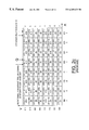
- FIG. 2B illustrates a 64-QAM table that can be used to generate the X and Y values.
- the TCM encoder 114 may also include a QAM constellation mapper to generate a QAM signal.
- the QAM constellation mapper can use the X and Y components as indices to a 64 QAM constellation mapping table to generate a corresponding QAM signal.
- FIG. 2C depicts a 64-QAM constellation mapping table. Given the five consecutive bits in each of the streams 212 , 214 , 220 , and 222 of the I and Q components, this double mapping process generates 5 consecutive QAM signals corresponding to the 5 consecutive QAM symbols.
- FIG. 3A illustrates a block diagram of a conventional 256-QAM TCM encoder 300 .
- the 256-QAM TCM encoder 300 encodes a trellis group of 38 bits into five consecutive 256-QAM symbols for mapping into five consecutive 64 QAM signals.
- the 256-QAM TCM encoder encodes the 38 input bits into 5 consecutive QAM symbols and signals.
- the 256-QAM TCM encoder 300 serially receives 128 7-bit FEC frames (e.g., packets).
- a parser 302 identifies a trellis group of 38 bits and assigns 19 bits as in-phase “I” component and the remaining 19 bits as quadrature “Q” component.
- the trellis group of 38 bits may either be in a non-sync trellis group bit order as indicated in row 304 or a sync trellis group bit order as indicated in row 306 .
- the parser 302 serializes the RS symbol bits beginning with the most significant bits of the first symbol of the first RS codeword following the frame sync. Bits are then placed in trellis group locations from RS symbols in the order as indicated in rows 304 or 306 . For the sync trellis group, RS bits begin at location I 1 instead of I 0 .
- the parser 302 assigns the individual bits of the I and Q symbols RS symbols into two groups as follows: three upper or most significant uncoded bit streams 308 and 310 and one lower or least significant bit coded bit stream 312 and 314 .
- the parser 302 outputs three upper uncoded bit streams 308 : one stream including bits I 3 , I 7 , I 11 , I 15 , and I 18 , another stream including bits I 2 , I 6 , I 10 , I 14 , and I 17 , and the remaining stream including bits I 1 , I 5 , I 9 , I 13 , and I 16 .
- the parser 302 For the lower coded bit stream 312 of the I component, the parser 302 outputs the bits I 0 , I 4 , I 8 , and I 12 for transmission to a differential encoder 316 .
- the lower coded I component bit stream 312 includes S 0 , S 2 , S 4 , and S 6 .
- the parser 302 outputs three upper uncoded bit streams 310 : one stream including bits Q 3 , Q 7 , Q 11 , Q 15 , and Q 18 , another stream including bits Q 2 , Q 6 , Q 10 , Q 14 , and Q 17 , and the remaining stream including bits Q 1 , Q 5 , Q 9 , Q 13 , and Q 16 .
- the parser 302 outputs the bits Q 0 , Q4, Q 8 , and Q 12 for transmission to the differential encoder 316 .
- the lower coded Q component bit stream 314 includes bits S 1 , S 3 , S 5 , and S 7 .
- the three upper uncoded bit streams 308 and 310 of I and Q components are transmitted to a 256-QAM mapper 318 .
- the differential encoder 316 receives the lower streams 312 and 314 of I and Q components in sequence and performs a 90 degree rotationally invariant trellis coding for each corresponding pair of I and Q bits as received. Specifically, the differential encoder 316 performs the rotationally invariant trellis coding for the I and Q bit pairs as they are received as follows: I 0 and Q 0 , I 4 and Q 4 , I 8 and Q 8 , and I 12 and Q 12 for a non-sync trellis group bit order and S 0 and S 1 , S 2 and S 3 , S 4 and S 5 , and S 6 and S 7 for a sync trellis group bit order.
- the differential encoder 316 then transmits the differentially encoded lower stream I and Q components to a pair of punctured binary convolutional encoders 320 and 322 , respectively.
- the punctured binary convolutional encoders 320 and 322 are rate 1 ⁇ 2 binary convolutional encoders and convolutionally encodes redundancy into the least significant bits of the I and Q symbols to improve signal-to-noise gain.
- This generator is equivalent to the generator matrix [1 ⁇ D 2 ⁇ D 4 , 1 ⁇ D ⁇ D 2 ⁇ D 3 ⁇ D 4 ], where D represents a delay element “Z ⁇ 1 .”
- the 1 ⁇ 2 rate encoder generates 8 output bits from the four input bits for each I and Q component streams 312 and 314 .
- the 8 output bits are then fed into a puncture matrix: 0001 1111 , where “0” denotes NO transmission and “1” represents transmission of the output signal.
- the puncture matrix essentially converts the rate 1 ⁇ 2 encoder to rate 4 ⁇ 5 to produce a single serial bit stream of 5 bits.
- the punctured binary convolutional encoders 320 and 322 encodes the 4 bits of the lower I and Q bit streams 216 and 218 , respectively, to generate 5 coded bits of I 0 ′, I 1 ′, I 2 ′, I 3 ′, and I 4 ′ as the convolutionally encoded lower I stream 324 and 5 coded bits of Q 0 ′, Q 1 ′, Q 2 ′, Q 3 ′, and Q 4 ′ as the convolutionally encoded lower Q stream 326 . Since the TCM encoder 300 encodes a trellis group of 38 input bits to generate 40 bits, the overall trellis coded modulation of the 256-QAM TCM encoder 300 yields a 38/40 rate.
- the 256 QAM mapper 318 receives three upper streams 308 and 310 and the lower streams 324 and 326 of the I and Q components for a total of six streams.
- Each of the streams includes 5 serial data bits. Since I and Q each includes 4 data streams, both I and Q streams can be used to define 4 bits of data at any one time. For example, the bits I 0 ′, I 1 , I 2 , and I 3 define an I component while the bits Q 0 ′, Q 1 , Q 2 , and Q 3 define a Q component.
- the 4 bits of I and Q components can then used in a double mapping process to generate a QAM signal.
- the 256-QAM Mapper 318 determines an 8-bit QAM symbol defined by “X” and “Y” components.
- Each of the “X” and “Y” components is 4 bits and represents 16-PAM signal constellation.
- FIG. 3B illustrates a 256-QAM table that can be used to generate the X and Y values.
- the TCM encoder 300 may also include a QAM constellation mapper 328 to generate a QAM signal.
- the QAM constellation mapper 328 can use the X and Y components as indices to a 256 QAM constellation mapping table to generate a corresponding QAM signal.
- FIG. 3C depicts a 256-QAM constellation mapping table. Given the five consecutive bits in each of the streams 308 , 310 , 324 , and 326 of the I and Q components, this double mapping process generates 5 consecutive QAM signals corresponding to the 5 consecutive 8-bit QAM symbols.
- the present invention fills these needs by providing a 64/256 QAM TCM decoder. It should be appreciated that the present invention can be implemented in numerous ways, including as a process, an apparatus, a system, a device, or a method. Several inventive embodiments of the present invention are described below.
- the present invention provides a quadrature amplitude modulation (QAM) trellis coded modulation (TCM) decoder for decoding a stream of QAM TCM signals.
- QAM quadrature amplitude modulation
- TCM trellis coded modulation
- Each of the signals has a plurality of associated branch metrics and has an in-phase component and a quadrature component.
- the in-phase component is defined by a plurality of in-phase symbols and the quadrature component is defined by a plurality of quadrature symbols.
- the QAM TCM decoder includes a first Viterbi decoder and a second Viterbi decoder.
- the first Viterbi decoder is configured to receive an in-phase component of a QAM TCM signal for decoding the associated in-phase symbols into an in-phase decoded bit and a plurality of uncoded in-phase bits.
- the second Viterbi decoder configured to receive a quadrature component of the QAM TCM signal for decoding the associated quadrature symbols into a quadrature decoded bit and a plurality of uncoded quadrature bits.
- the QAM TCM decoder is preferably configured to decode 64- or 256-QAM TCM signals.
- the present invention provides a method for decoding a stream of QAM TCM signals to generate decoded in-phase and quadrature bits and a plurality of uncoded in-phase and quadrature bits.
- Each of the signals has a plurality of associated branch metrics, and each signal has an in-phase component and a quadrature component.
- the in-phase component is defined by a plurality of in-phase symbols and the quadrature component is defined by a plurality of quadrature symbols.
- the method comprises: a) receiving a stream of QAM TCM signals; b) demodulating each of the QAM TCM signals into an in-phase component and a quadrature component; c) receiving an in-phase component of a QAM TCM signal; d) receiving a quadrature component of the QAM TCM signal; e) generating an in-phase decoded bit and a plurality of uncoded in-phase bits by decoding the associated in-phase symbols; and f) generating a quadrature decoded bit and a plurality of uncoded quadrature bits by decoding the associated quadrature symbols.
- a QAM TCM decoder for decoding a stream of QAM TCM signals.
- Each of the signals has a plurality of associated branch metrics, and each signal has an in-phase component and a quadrature component.
- the in-phase component is defined by a plurality of in-phase symbols and the quadrature component is defined by a plurality of quadrature symbols.
- the QAM TCM decoder includes a first decoding means and a second decoding means.
- the first decoding means is configured to receive an in-phase component of a QAM TCM signal for decoding the associated in-phase symbols into an in-phase decoded bit and a plurality of uncoded in-phase bits.
- the second decoding means configured to receive a quadrature component of the QAM TCM signal for decoding the associated quadrature symbols into a quadrature decoded bit and a plurality of uncoded quadrature bits.
- the first and second decoding means are adapted to decode 64- or 256-QAM TCM signals.
- the 64/256-QAM TCM decoder of the present invention provides the benefit of decoding in-phase and quadrature components independently and separately. Since in-phase and quadrature component of 64/256-QAM TCM code can be decoded independently, the present invention reduces branch metric calculation and trellis complexity. In addition, the TCM decoder of the present invention can decode 64- or 256-QAM TCM signals. Other aspects and advantages of the invention will become apparent from the following detailed description, taken in conjunction with the accompanying drawings, illustrating by way of example the principles of the invention.
- FIG. 1 illustrates a conventional cable modem transmission block diagram depicting a forward error correction (FEC) scheme in accordance with standard of ITU-T Recommendation J-83 Annex B.
- FEC forward error correction
- FIG. 2A illustrates a block diagram of a conventional TCM encoder.
- FIG. 2B illustrates a 64-QAM table that can be used to generate the X and Y values.
- FIG. 2C depicts a 64-QAM constellation mapping table.
- FIG. 3A illustrates a block diagram of a conventional 256-QAM TCM encoder.
- FIG. 3B illustrates a 256-QAM table that can be used to generate the X and Y values.
- FIG. 3C depicts a 256-QAM constellation mapping table.
- FIG. 4A illustrates a block diagram of a 64/256 QAM TCM decoder in accordance with one embodiment of the present invention.
- FIG. 4B illustrates a block diagram of the 64/256 QAM TCM decoder 400 including a serial-to-parallel circuitry.
- FIG. 5A illustrates a block diagram of the Viterbi decoder for decoding a 64/256-QAM TCM signal stream in accordance with one embodiment of the present invention.
- FIG. 5B illustrates a more detailed block diagram of the Viterbi decoder for decoding 64/256-QAM TCM signals in accordance with one embodiment of the present invention.
- FIG. 6A illustrates a block diagram of a Viterbi decoder for decoding 64/256-QAM TCM signals in accordance with an alternative embodiment of the present invention.
- FIG. 6B illustrates a more detailed block diagram of the Viterbi decoder in accordance with one embodiment of the present invention.
- FIG. 4A illustrates a block diagram of a 64/256 QAM TCM decoder 400 in accordance with one embodiment of the present invention.
- the 64 QAM TCM decoder 400 includes a 64/256 QAM demodulator 402 , a depuncture circuitry 404 , and a rate-1 ⁇ 2 Viterbi decoder 406 .
- the 64/256-QAM demodulator 402 receives an analog 64- or 256-QAM signal stream through a cable network and determines whether the received signal is a 64- or 256-QAM signal.
- the 64/256-QAM demodulator generates a 1-bit indicator signal for indicating whether the received signal is a 64- or 256-QAM signal and transmits the QAM indicator signal to other parts of the circuitry such as the depuncture circuitry 404 and the Viterbi decoder 406 .
- the QAM demodulator 402 receives a stream of QAM signals and demodulates the received QAM signals into an in-phase component X I and a quadrature component Y Q .
- the QAM demodulator 402 receives five consecutive signals (e.g., S 0 , S 1 , S 2 , S 3 , S 4 ) and demodulates the signals into in-phase component X I and quadrature component Y Q of five consecutive in-phase and quadrature symbols each, respectively.
- the in-phase component X I includes five consecutive in-phase symbols (e.g., X 0 , X 1 , X 2 , X 3 , X 4 ).
- the quadrature component Y Q includes five consecutive quadrature symbols (e.g., Y 0 , Y 1 , Y 2 , Y 3 , Y 4 ).
- the depuncture circuitry 404 receives the five consecutive in-phase and quadrature symbols in parallel and generates a depunctured in-phase component X 1 ′ and a depunctured quadrature component Y Q ′.
- the depuncture circuitry 407 generates the in-phase component X I ′ of [*, *, *, X 0 : X 4 , X 3 , X 2 , X 1 ] and the depuncture circuitry 408 produces the quadrature component Y Q ′ of [*, *, *, Y 0 : Y 4 , Y 3 , Y 2 , Y 1 ], wherein * denotes a dummy variable.
- the eight consecutive in-phase component X I ′ and quadrature component Y Q ′ symbols are then transmitted pair wise in parallel to the Viterbi decoder 406 .
- the symbols X 0 and X 1 are transmitted pair wise in parallel to the Viterbi decoder 406 for simultaneous processing.
- the symbols Y 0 and Y 1 are transmitted pair wise for processing by the Viterbi decoder 406 .
- the depuncture circuitry 404 adds or inserts 3 dummy symbols (e.g., *) to each of the received five consecutive symbols of X I and Y Q components and essentially converts the rate 4 ⁇ 5 soft output stream into rate 1 ⁇ 2 output stream.
- 3 dummy symbols e.g., *
- the in-phase and quadrature depuncture circuitry 407 and 408 generate a depunctured soft in-phase and quadrature outputs X I ′ and Y Q ′, respectively, for transmission to the Viterbi decoder 406 .
- the Viterbi decoder 406 includes an in-phase Viterbi decoder 412 and a quadrature Viterbi decoder 414 .
- the in-phase Viterbi decoder 412 receives the in-phase component X I ′ and generates a decoded in-phase (e.g., I LSB ) bit and uncoded bits or MSBs of the in-phase component (i.e., X MSB ).
- the quadrature Viterbi decoder 414 receives the quadrature component Y Q ′ and generates a decoded quadrature (e.g., Q LSB ) bit and uncoded bits or MSBs of the quadrature component (i.e., Y MSB ) for each pair of symbols received.
- the in-phase Viterbi decoder 412 receives four consecutive pairs of in-phase component X I ′ and generates four consecutive decoded in-phase (e.g., I LSB ) bits and uncoded bits or MSBs of the in-phase component (i.e., X MSB ).
- the quadrature Viterbi decoder 414 preferably receives four consecutive pairs of quadrature component Y Q ′ and generates a decoded quadrature (e.g., Q LSB ) bit and uncoded bits or MSBs of the quadrature component (i.e., Y MSB ) for each pair of symbols received.
- the Viterbi decoder 406 thus outputs in-phase component including I LSB and X MSB and quadrature component including Q LSB and Y MSB .
- FIG. 4B illustrates a block diagram of the 64/256 QAM TCM decoder 400 including a serial-to-parallel circuitry 420 .
- the serial-to parallel circuitry 420 includes an in-phase serial-to-parallel circuitry 422 and a quadrature serial-to-parallel circuitry 424 .
- the in-phase serial-to-parallel circuitry 422 is coupled to the in-phase depuncture circuitry 407 to receive the in-phase component X 1 ′ symbols for arranging the in-phase symbols from a serial into a parallel sequence for input into the in-phase Viterbi decoder 412 .
- the quadrature serial-to-parallel circuitry 424 is coupled to the quadrature depuncture circuitry 408 to receive quadrature symbols Y Q ′ for arranging the quadrature symbols from a serial into a parallel sequence for input into the quadrature Viterbi decoder 414 .
- the in-phase and quadrature serial-to-parallel circuitry 422 and 424 receive eight consecutive in-phase and quadrature symbols, respectively and convert the symbols into four consecutive pairs of in-phase and quadrature symbols, respectively.
- the in-phase and quadrature serial-to-parallel circuitry 422 and 424 then transmit the four consecutive pairs of in-phase and quadrature symbols, respectively, in parallel into the in-phase and quadrature Viterbi decoders 412 and 414 , respectively.
- the Viterbi decoder 406 receives the depunctured in-phase and quadrature components from the depuncture circuitry 404 in parallel and decodes the soft in-phase and quadrature data streams from the 64/256-QAM demodulator 402 separately and independently. In a preferred embodiment, the Viterbi decoder 406 receives the four consecutive pairs of in-phase and quadrature symbols in parallel.
- the Viterbi decoder 406 preferably includes an in-phase Viterbi decoder 412 for decoding the in-phase component and a quadrature Viterbi decoder 414 for decoding the quadrature component.
- the in-phase Viterbi decoder 412 receives the four consecutive in-phase component symbols while the quadrature Viterbi decoder 414 receives the four consecutive quadrature component symbols.
- Each of the Viterbi decoders 412 and 414 generates one coded information bit for convolutional code and 4 uncoded bits for 64-QAM signals or 6 uncoded bits for 256-QAM signals for the respective component of the data stream.
- the Viterbi decoder 406 receives the indicator signal from the QAM demodulator 402 , which indicates whether the received signals are 64- or 256-QAM modulated signals. In response to the indicator signal, the Viterbi decoder 406 decodes the received signals as either 64- or 256-QAM TCM signals. In particular, the Viterbi decoders 412 and 414 decode the in-phase and quadrature components, respectively, of the received signals in accordance with the indicator signal.
- FIG. 5A illustrates a block diagram of the Viterbi decoder 412 for decoding a 64/256-QAM TCM signal stream in accordance with one embodiment of the present invention. While FIG. 5A illustrates the Viterbi decoder 412 , it should be appreciated that the Viterbi decoder 412 can also be utilized as the Viterbi decoder 414 in FIG. 4 to decode the quadrature components as well.
- the Viterbi decoder 412 includes a branch metric generator 502 , an add-compare-select circuitry 504 coupled to the branch metric generator 502 , and a trace-back circuitry 506 coupled to the add-compare-select circuitry 504 .
- the branch metric generator 502 receives in-phase components of a 64/256-QAM TCM signals and extracts the associated branch metrics.
- the Viterbi decoder 412 receives four consecutive pairs of in-phase component symbols. Since the TCM encoder uses a rate-1 ⁇ 2 16-state convolutional code, each of the four branches in a 16-state trellis (i.e., 00, 01, 10, 11) has four distinct labels. Accordingly, only the branch metrics for these four distinct branch labels (e.g., BM00, BM01, BM10, and BM11) are computed. In this setting, two consecutive soft data bits are fed into the branch metric generator 502 because each distinct label has two bits.
- LSBs least significant bits
- MSBs most significant bits
- a label with minimum branch metric can also be determined.
- a label with minimum branch metric can be determined.
- the branch metric generator 502 then adds each branch metric and stores a pair of two uncoded bits (e.g., MSBs) from stored labels with minimum branch metric. In this manner, the branch metric generator circuitry 502 determines the uncoded bits (e.g., MSBs) and minimum distance for each branch.
- a pair of two uncoded bits e.g., MSBs
- the two bits are used as the LSBs for representing 16-PAM signal constellation mapping, i.e., ( ⁇ 15, ⁇ 13, ⁇ 11, ⁇ 9, ⁇ 7, ⁇ 5, ⁇ 3, ⁇ 1, 1, 3, 5, 7, 9, 11, 13, 15) in decoding 256-QAM signals.
- a label with minimum branch metric can also be determined.
- a label with minimum branch metric can be determined.
- the branch metric generator 502 then adds each branch metric and stores a pair of three uncoded bits (e.g., MSBs) from stored labels with minimum branch metric. In this manner, the branch metric generator circuitry 602 determines the uncoded bits (e.g., MSBs) and minimum distance for each branch.
- the add-compare-select circuitry 504 receives the uncoded bits and the minimum distances for each branch from the branch metric generator circuitry 502 . The add-compare-select circuitry 504 then compares the branch metrics of each state label and determines the smallest branch metric for each state. The add-compare-select circuitry 504 then assigns a decision bit to the smallest branch metric. For each 64-QAM signal, the Viterbi decoder 412 thus generates the state decision bit and 4 uncoded bits in the case of 64-QAM signals or 6 uncoded bits for 256-QAM signals.
- the add-compare-select circuitry 504 updates path metrics recursively.
- the add-compare-select circuitry 504 preferably includes a fixed add-compare-select unit for each state of trellis so that the Viterbi decoder 408 can select the minimum metric path between the two competing paths entering the state and store the path metric of the surviving path.
- Each of the add-compare-select unit is assigned to a unique state of the trellis, which is used as a label for the associated add-compare-select unit.
- each add-compare-select unit receives path metrics from two add-compare-select units and sends the path metrics to two other add-compare-select units. Any two add-compare-select units with labels of the form 0X and 1X receive the path metrics from the same pair of add-compare-select units with labels X0 and X1, where X denotes either 1 or 0.
- the pair of add-compare-select units (0X, 1X) forms a hardware entity, which is referred to as a double-add-compare-select unit.
- the wiring between the add-compare-select units is isomorphic to the state diagram of the convolutional code. Using this scheme, the add-compare-select circuitry 504 generates and feeds 4 (for 64-QAM signals) or 6 (for 256-QAM signals) uncoded bits and a state decision bit to the trace-back circuitry.
- the trace-back circuitry 506 uses the received decision bits to identify surviving paths for all states. In addition, the trace-back circuitry 506 determines a unique Maximum Likelihood (ML) path by tracing back all the surviving paths to their common root. The unique ML path is preferably determined by tracing back one single path down to coding depth levels.
- ML Maximum Likelihood
- the trace-back circuitry 506 generates eight consecutive 2-bit pairs for parallel branches and 4 information bits from 8 consecutive in-phase component of the 64-QAM signals.
- the trace-back circuitry 506 generates eight consecutive 3-bit pairs for parallel branches and 4 information bits from 8 consecutive in-phase component of the 256-QAM signals.
- the four recovered information bits are then fed into a binary convolutional encoder to produce 8 LSBs. These eight LSBs are combined with eight consecutive 2-bit pair for 64-QAM signals or 3-bit pair for 256-QAM signals and fed into a puncture circuitry to generate 5 consecutive 3-bit “X” components in the case of 64-QAM signals or 4-bit “X-components” in the case of 256-QAM signals. Five consecutive 3-bit or 4-bit quadrature “Y- components” are likewise generated by the Viterbi decoder 414 in a similar manner.
- FIG. 5B illustrates a more detailed block diagram of the Viterbi decoder 412 for decoding 64/256-QAM TCM signals in accordance with one embodiment of the present invention.
- the trace-back circuitry 506 includes a storage unit 508 , a trace-back unit 510 , a last-in-first-out (FIFO) unit 512 , and a trace-back controller 514 .
- the branch metric generator 502 and the add-select-compare circuitry 504 perform the functions discussed previously.
- the branch metric generator 502 generates and transmits branch metrics BM 00 , BM 01 , BM 10 , and BM 11 to the add-compare-select circuitry 502 along with the uncoded bits.
- the add-compare-select circuitry 504 then compares the branches for each of the states and determines the branch with the smallest branch metric, which is assigned with a decision bit, as mentioned above in conjunction with FIG. 5 A.
- the outputs of the add-compare-select circuitry 504 are stored in the storage unit 508 of the trace-back circuitry 506 .
- the storage unit 508 includes three random access memories (RAMs) M1, M2, and M3, each of which is (16 ⁇ 7) ⁇ 32 or 112 ⁇ 32 bits to accommodate the larger memory requirements of 256-QAM signals, where 16 corresponds to 16 states, 7 corresponds to 6 uncoded bits and 1 information bit for 256-QAM signals, 32 corresponds to 24-read and 8-write operation for read-three-write-one mode.
- RAMs random access memories
- M1, M2, and M3 each of which is (16 ⁇ 7) ⁇ 32 or 112 ⁇ 32 bits to accommodate the larger memory requirements of 256-QAM signals, where 16 corresponds to 16 states, 7 corresponds to 6 uncoded bits and 1 information bit for 256-QAM signals, 32 corresponds to 24-read and 8-write operation for read-three-write-one mode.
- For 64-QAM signals only 5 bits are required for 4 uncoded bits and 1
- the add-compare-select circuitry 504 writes once into a RAM and the trace-back circuitry 506 reads three times from the RAMs M1, M2, and M3 of the storage unit 508 .
- the trace-back controller 514 provides the write and read addresses.
- the trace-back unit 510 preferably traces back three consecutive 16 states at a time and outputs one information bit, which is equivalent to the LSB of the current state, and the uncoded information bits.
- the trace-back circuitry 506 preferably utilizes trace back depth of 72 based on index ⁇ of 3 and coding depth of 48.
- the trace-back unit 510 writes 1 decoded bit and MSBs into the LIFO 512.
- the LIFO 512 receives three symbols in parallel. In this LIFO configuration, writing to the LIFO 512 takes 24 clock cycles and reading from the LIFO 512 takes 24 clock cycles. However, only 24 symbols on 72 input symbols are read due to the coding depth of 48 symbols. Eventually, the next valid data is ready to be written into the LIFO 512 after 24 clock cycles.
- the trace-back controller 514 controls the burst input/output of the LIFO 512 by transmitting a burst period signal.
- FIG. 6A illustrates a block diagram of a Viterbi decoder 600 for decoding 64/256-QAM TCM signals in accordance with another embodiment of the present invention.
- the Viterbi decoder 600 can be employed as the Viterbi decoders 412 and 414 in FIG. 4 to decode the in-phase and quadrature components.
- the Viterbi decoder 600 includes a branch metric generator 602 , an add-compare-select circuitry 604 , and a trace-back circuitry 606 .
- the Viterbi decoder 600 also includes a delay unit 608 .
- the delay unit 608 is preferably implemented as a RAM such as a DRAM, SRAM, etc.
- the branch metric generator 602 generates four 4- or 6-bit uncoded bits (e.g., MSBs) and minimum branch metric distances as discussed previously.
- the generated minimum branch metric distances for branch metrics with labels 00, 10, 01, 11 are then transmitted to the add-compare-select circuitry 604 .
- the generated uncoded bits for BM00, BM10, BM01, BM11 are transmitted to the delay unit 608 .
- the add-compare-select circuitry 604 generates a state decision bit for each QAM signal and transmits the generated bits to the trace-back circuitry 606 .
- the trace-back circuitry 606 produces 1 coded information bit and a control signal for selecting one of the four 4- or 6-bit uncoded (i.e., MSBs) bits held in the delay unit 608 .
- the Viterbi decoder 600 thus outputs 1 coded information bit and a 4- or 6-bit uncoded bits.
- FIG. 6B illustrates a more detailed block diagram of the Viterbi decoder 600 in accordance with one embodiment of the present invention.
- the Viterbi decoder 600 includes a branch metric generator 602 , an add-compare-select circuitry 604 , a trace-back circuitry 606 , a delay unit 608 , and a multiplexer 618 .
- the trace-back circuitry 606 further includes a storage unit 610 , a trace-back unit 612 , a LIFO unit 614 , and a trace-back controller 616 In this configuration, the outputs of the add-compare-select circuitry 604 are stored in the storage unit 610 of the trace-back circuitry 606 .
- the storage unit 610 includes three RAMs of 1 ⁇ 16 ⁇ 32 bits each to store the decision bits for either 64- or 256-QAM signals, where 1 bit corresponds to a decision bit, 16 corresponds to 16 states, and 32 corresponds to 24-read and 8-write operation for read-three-write-one mode.
- the trace-back circuitry 606 generates three bits, one for decoded bit and two bits to determine the coset of the uncoded bits, i.e., the MSBs.
- the delay unit 608 provides the required delay to transmit the four branch metrics to the multiplexer 618 .
- the LIFO unit 614 transmits the 2-bit coset selection signal to the multiplexer 618 , which selects one of the four branch metrics as the output of 4 or 6 uncoded bits.
- the 64/256 QAM TCM decoder of the present invention provides the benefit of decoding in-phase and quadrature components independently and separately. Since in-phase and quadrature component of 64/256 QAM TCM code can be decoded independently, the present invention reduces branch metric calculation and trellis complexity. In addition, the TCM decoder of the present invention can decode both 64/256 QAM TCM code.
- the TCM decoder thus generates eight consecutive 3-bit pairs for parallel branches and 4 information bits from 8 consecutive in-phase component of 256-QAM signals. These recovered data bits can be used to recover the “I” and “Q” components of the original signal as discussed and illustrated in a co-pending U.S. patent application having Ser. No. 09/065,751 (Attorney Docket No.
Abstract
Description
Claims (41)
Priority Applications (1)
| Application Number | Priority Date | Filing Date | Title |
|---|---|---|---|
| US09/066,048 US6269129B1 (en) | 1998-04-24 | 1998-04-24 | 64/256 quadrature amplitude modulation trellis coded modulation decoder |
Applications Claiming Priority (1)
| Application Number | Priority Date | Filing Date | Title |
|---|---|---|---|
| US09/066,048 US6269129B1 (en) | 1998-04-24 | 1998-04-24 | 64/256 quadrature amplitude modulation trellis coded modulation decoder |
Publications (1)
| Publication Number | Publication Date |
|---|---|
| US6269129B1 true US6269129B1 (en) | 2001-07-31 |
Family
ID=22066933
Family Applications (1)
| Application Number | Title | Priority Date | Filing Date |
|---|---|---|---|
| US09/066,048 Expired - Lifetime US6269129B1 (en) | 1998-04-24 | 1998-04-24 | 64/256 quadrature amplitude modulation trellis coded modulation decoder |
Country Status (1)
| Country | Link |
|---|---|
| US (1) | US6269129B1 (en) |
Cited By (31)
| Publication number | Priority date | Publication date | Assignee | Title |
|---|---|---|---|---|
| US20020027956A1 (en) * | 2000-07-11 | 2002-03-07 | Lg Electronics, Inc. | Communication system and method for transmitting signal in the same |
| US6438112B1 (en) * | 1997-06-13 | 2002-08-20 | Canon Kabushiki Kaisha | Device and method for coding information and device and method for decoding coded information |
| US20020118772A1 (en) * | 2000-12-21 | 2002-08-29 | Jingdong Lin | Channel optimization system |
| US6507619B1 (en) * | 2000-03-24 | 2003-01-14 | Atheros Communications, Inc. | Decoding system and method for digital communications |
| GB2377867A (en) * | 2001-04-12 | 2003-01-22 | Supergold Comm Ltd | A 2/3 rate binary convolutional encoder |
| US20030058954A1 (en) * | 2001-05-31 | 2003-03-27 | Allen He | Method and apparatus for a complementary encoder/decoder |
| US20030058955A1 (en) * | 2001-07-11 | 2003-03-27 | Sreen Raghavan | High-speed communications transceiver |
| US6549584B1 (en) * | 1999-06-30 | 2003-04-15 | Texas Instruments Incorporated | Coding scheme for cable modems |
| US20030087634A1 (en) * | 2001-07-11 | 2003-05-08 | Raghavan Sreen A. | 10165368High-speed multi-channel communications transceiver with inter-channel interference filter |
| US20030123579A1 (en) * | 2001-11-16 | 2003-07-03 | Saeid Safavi | Viterbi convolutional coding method and apparatus |
| US20030134607A1 (en) * | 2001-07-11 | 2003-07-17 | Raghavan Sreeen A. | Multi-channel communications transceiver |
| WO2003088607A1 (en) * | 2002-04-12 | 2003-10-23 | Azea Networks Limited | Transmission system |
| US6654929B1 (en) * | 1999-10-01 | 2003-11-25 | Matsushita Electric Industrial Co., Ltd. | Viterbi decoder and Viterbi decoding method |
| US20040064781A1 (en) * | 1999-10-01 | 2004-04-01 | Matsushita Electric Industrial Co., Ltd. | Viterbi decoder and Viterbi decoding method |
| US6738949B2 (en) * | 1998-05-13 | 2004-05-18 | Matsushita Electric Industrial Co., Ltd. | Error correction circuit and error correction method |
| US6769090B1 (en) * | 2000-08-14 | 2004-07-27 | Virata Corporation | Unified technique for multi-rate trellis coding and decoding |
| US20040247022A1 (en) * | 2003-06-03 | 2004-12-09 | Raghavan Sreen A. | Near-end, far-end and echo cancellers in a multi-channel transceiver system |
| US20050018635A1 (en) * | 1999-11-22 | 2005-01-27 | Ipr Licensing, Inc. | Variable rate coding for forward link |
| US20050169319A1 (en) * | 2003-04-25 | 2005-08-04 | Farrokh Mohamadi | Ten Gigabit copper physical layer system |
| US7043681B2 (en) | 2002-05-03 | 2006-05-09 | Ibiquity Digital Corporation | Digital audio broadcasting method and apparatus using complementary pattern-mapped convolutional codes |
| US7065696B1 (en) * | 2003-04-11 | 2006-06-20 | Broadlogic Network Technologies Inc. | Method and system for providing high-speed forward error correction for multi-stream data |
| US20070076816A1 (en) * | 1999-03-05 | 2007-04-05 | Ipr Licensing, Inc. | Maximizing data rate by adjusting codes and code rates in CDMA system |
| US20070266303A1 (en) * | 2006-04-27 | 2007-11-15 | Qualcomm Incorporated | Viterbi decoding apparatus and techniques |
| US7298798B1 (en) * | 2001-08-24 | 2007-11-20 | Mediatek, Inc. | Method and system for decoding block codes |
| US20070274407A1 (en) * | 2000-03-24 | 2007-11-29 | Thomson John S | Decoding System And Method For Digital Communications |
| US20080072124A1 (en) * | 2006-09-05 | 2008-03-20 | Mediatek Inc. | Apparatus and method for detecting puncture position in a symbol stream encoded by punctured convolutional coding scheme |
| US7593380B1 (en) | 1999-03-05 | 2009-09-22 | Ipr Licensing, Inc. | Variable rate forward error correction for enabling high performance communication |
| WO2014043007A1 (en) * | 2012-09-11 | 2014-03-20 | Baker Hughes Incorporated | Apparatus and method for coding and modulation |
| CN107683592A (en) * | 2016-05-11 | 2018-02-09 | 华为技术有限公司 | Data processing method, device and system |
| US10020912B2 (en) | 2013-03-13 | 2018-07-10 | Sans R&D, Llc | Method and a system for a receiver design in bandwidth constrained communication systems |
| WO2019173027A1 (en) * | 2018-03-05 | 2019-09-12 | Qualcomm Incorporated | High-rate trellis coded modulations |
Citations (4)
| Publication number | Priority date | Publication date | Assignee | Title |
|---|---|---|---|---|
| US5396518A (en) * | 1993-05-05 | 1995-03-07 | Gi Corporation | Apparatus and method for communicating digital data using trellis coding with punctured convolutional codes |
| US5469452A (en) * | 1991-09-27 | 1995-11-21 | Qualcomm Incorporated | Viterbi decoder bit efficient chainback memory method and decoder incorporating same |
| US5737365A (en) * | 1995-10-26 | 1998-04-07 | Motorola, Inc. | Method and apparatus for determining a received signal quality estimate of a trellis code modulated signal |
| US6005897A (en) * | 1997-12-16 | 1999-12-21 | Mccallister; Ronald D. | Data communication system and method therefor |
-
1998
- 1998-04-24 US US09/066,048 patent/US6269129B1/en not_active Expired - Lifetime
Patent Citations (4)
| Publication number | Priority date | Publication date | Assignee | Title |
|---|---|---|---|---|
| US5469452A (en) * | 1991-09-27 | 1995-11-21 | Qualcomm Incorporated | Viterbi decoder bit efficient chainback memory method and decoder incorporating same |
| US5396518A (en) * | 1993-05-05 | 1995-03-07 | Gi Corporation | Apparatus and method for communicating digital data using trellis coding with punctured convolutional codes |
| US5737365A (en) * | 1995-10-26 | 1998-04-07 | Motorola, Inc. | Method and apparatus for determining a received signal quality estimate of a trellis code modulated signal |
| US6005897A (en) * | 1997-12-16 | 1999-12-21 | Mccallister; Ronald D. | Data communication system and method therefor |
Non-Patent Citations (2)
| Title |
|---|
| Stephen B. Wicker, "The Viterbi Decoding Algorithm", pp. 290-331, 1995, Error Control Systems for Digital Communication and Storage, Prentice Hall, New Jersey. |
| Unknown, "Digital Multi-Programme Systems for Television Sound and Data Services for Cable Distribution", 10/95, International Telecommunication Union (ITU), Recommendation J.83. |
Cited By (77)
| Publication number | Priority date | Publication date | Assignee | Title |
|---|---|---|---|---|
| US6438112B1 (en) * | 1997-06-13 | 2002-08-20 | Canon Kabushiki Kaisha | Device and method for coding information and device and method for decoding coded information |
| US6738949B2 (en) * | 1998-05-13 | 2004-05-18 | Matsushita Electric Industrial Co., Ltd. | Error correction circuit and error correction method |
| US20040158798A1 (en) * | 1998-05-13 | 2004-08-12 | Hiroyuki Senda | Error correction circuit and error correction method |
| US8068474B2 (en) | 1999-03-05 | 2011-11-29 | Ipr Licensing, Inc. | Variable rate coding for enabling high performance communication |
| US8204140B2 (en) | 1999-03-05 | 2012-06-19 | Ipr Licensing, Inc. | Subscriber unit and method for variable forward error correction (FEC) decoding |
| US7826437B2 (en) | 1999-03-05 | 2010-11-02 | Ipr Licensing, Inc. | Variable rate coding for enabling high performance communication |
| US20110047444A1 (en) * | 1999-03-05 | 2011-02-24 | Interdigital Technology Corporation | Variable rate coding for enabling high performance communication |
| US20100011272A1 (en) * | 1999-03-05 | 2010-01-14 | Ipr Licensing, Inc. | Variable rate coding for enabling high performance communication |
| US9306703B2 (en) | 1999-03-05 | 2016-04-05 | Intel Corporation | Variable rate coding for enabling high performance communication |
| US20070076816A1 (en) * | 1999-03-05 | 2007-04-05 | Ipr Licensing, Inc. | Maximizing data rate by adjusting codes and code rates in CDMA system |
| US8964909B2 (en) | 1999-03-05 | 2015-02-24 | Intel Corporation | Maximizing data rate by adjusting codes and code rates |
| US8437329B2 (en) | 1999-03-05 | 2013-05-07 | Intel Corporation | Variable rate coding for enabling high performance communication |
| US9369235B2 (en) | 1999-03-05 | 2016-06-14 | Intel Corporation | Maximizing data rate by adjusting codes and code rates |
| US7593380B1 (en) | 1999-03-05 | 2009-09-22 | Ipr Licensing, Inc. | Variable rate forward error correction for enabling high performance communication |
| US20090135950A1 (en) * | 1999-03-05 | 2009-05-28 | Ipr Licensing Inc. | Maximizing data rate by adjusting codes and code rates |
| US7502424B2 (en) | 1999-03-05 | 2009-03-10 | Ipr Licensing, Inc. | Maximizing data rate by adjusting codes and code rates |
| US6549584B1 (en) * | 1999-06-30 | 2003-04-15 | Texas Instruments Incorporated | Coding scheme for cable modems |
| US20040064781A1 (en) * | 1999-10-01 | 2004-04-01 | Matsushita Electric Industrial Co., Ltd. | Viterbi decoder and Viterbi decoding method |
| US6654929B1 (en) * | 1999-10-01 | 2003-11-25 | Matsushita Electric Industrial Co., Ltd. | Viterbi decoder and Viterbi decoding method |
| US7225393B2 (en) | 1999-10-01 | 2007-05-29 | Matsushita Electric Industrial Co., Ltd. | Viterbi decoder and Viterbi decoding method |
| US9294222B2 (en) | 1999-11-22 | 2016-03-22 | Intel Corporation | Variable rate coding for forward and reverse link |
| US20090010368A1 (en) * | 1999-11-22 | 2009-01-08 | Ipr Licensing Inc. | Variable rate coding for forward link |
| US20050018635A1 (en) * | 1999-11-22 | 2005-01-27 | Ipr Licensing, Inc. | Variable rate coding for forward link |
| US8194783B2 (en) | 1999-11-22 | 2012-06-05 | Ipr Licensing, Inc. | Variable rate coding for a forward and reverse link |
| US7426241B2 (en) * | 1999-11-22 | 2008-09-16 | Ipr Licensing, Inc. | Variable rate coding for forward link |
| US7636400B2 (en) | 2000-03-24 | 2009-12-22 | Atheros Communications, Inc. | Decoding system and method for digital communications |
| US20070274407A1 (en) * | 2000-03-24 | 2007-11-29 | Thomson John S | Decoding System And Method For Digital Communications |
| US20100098183A1 (en) * | 2000-03-24 | 2010-04-22 | Thomson John S | Decoding System And Method For Digital Communications |
| US7924932B2 (en) | 2000-03-24 | 2011-04-12 | Atheros Communications, Inc. | Decoding system and method for digital communications |
| US6507619B1 (en) * | 2000-03-24 | 2003-01-14 | Atheros Communications, Inc. | Decoding system and method for digital communications |
| US20020027956A1 (en) * | 2000-07-11 | 2002-03-07 | Lg Electronics, Inc. | Communication system and method for transmitting signal in the same |
| US7251285B2 (en) * | 2000-07-11 | 2007-07-31 | Lg Electronics Inc. | Method and apparatus for transmitting and receiving using turbo code |
| US6769090B1 (en) * | 2000-08-14 | 2004-07-27 | Virata Corporation | Unified technique for multi-rate trellis coding and decoding |
| US7606317B2 (en) | 2000-12-21 | 2009-10-20 | Agere Systems Inc. | Channel optimization system |
| US20020118772A1 (en) * | 2000-12-21 | 2002-08-29 | Jingdong Lin | Channel optimization system |
| US20060176964A1 (en) * | 2000-12-21 | 2006-08-10 | Agere Systems Inc. | Channel optimization system |
| US7065151B2 (en) * | 2000-12-21 | 2006-06-20 | Agere Systems Inc. | Channel optimization system |
| GB2377867A (en) * | 2001-04-12 | 2003-01-22 | Supergold Comm Ltd | A 2/3 rate binary convolutional encoder |
| US7313192B2 (en) * | 2001-05-31 | 2007-12-25 | Nxp B.V. | Method and apparatus for a complementary encoder/decoder |
| US20030058954A1 (en) * | 2001-05-31 | 2003-03-27 | Allen He | Method and apparatus for a complementary encoder/decoder |
| US7403752B2 (en) | 2001-07-11 | 2008-07-22 | Vativ Technologies, Inc. | Multi-channel communications transceiver |
| US7295623B2 (en) | 2001-07-11 | 2007-11-13 | Vativ Technologies, Inc. | High-speed communications transceiver |
| US20030058955A1 (en) * | 2001-07-11 | 2003-03-27 | Sreen Raghavan | High-speed communications transceiver |
| US20030081693A1 (en) * | 2001-07-11 | 2003-05-01 | Raghavan Sreen A. | Low complexity high-speed communications transceiver |
| US20030087634A1 (en) * | 2001-07-11 | 2003-05-08 | Raghavan Sreen A. | 10165368High-speed multi-channel communications transceiver with inter-channel interference filter |
| US7590168B2 (en) | 2001-07-11 | 2009-09-15 | Entropic Communications, Inc. | Low complexity high-speed communications transceiver |
| US20030134607A1 (en) * | 2001-07-11 | 2003-07-17 | Raghavan Sreeen A. | Multi-channel communications transceiver |
| US7236757B2 (en) | 2001-07-11 | 2007-06-26 | Vativ Technologies, Inc. | High-speed multi-channel communications transceiver with inter-channel interference filter |
| US7298798B1 (en) * | 2001-08-24 | 2007-11-20 | Mediatek, Inc. | Method and system for decoding block codes |
| US20030123579A1 (en) * | 2001-11-16 | 2003-07-03 | Saeid Safavi | Viterbi convolutional coding method and apparatus |
| WO2003088607A1 (en) * | 2002-04-12 | 2003-10-23 | Azea Networks Limited | Transmission system |
| US8971171B2 (en) | 2002-04-12 | 2015-03-03 | Xtera Communications, Inc. | Reduced FEC overhead in an optical transmission system |
| US20060050803A1 (en) * | 2002-04-12 | 2006-03-09 | Stuart Barnes | Transmission system |
| US20050213966A1 (en) * | 2002-04-12 | 2005-09-29 | Martin Chown | Transmission system |
| US7978973B2 (en) | 2002-04-12 | 2011-07-12 | Xtera Communications Ltd. | Transmission system |
| US20090269068A1 (en) * | 2002-04-12 | 2009-10-29 | Azea Networks Limited | Transmission system |
| US7526205B2 (en) | 2002-04-12 | 2009-04-28 | Azea Networks Limited | Transmission system |
| US7043681B2 (en) | 2002-05-03 | 2006-05-09 | Ibiquity Digital Corporation | Digital audio broadcasting method and apparatus using complementary pattern-mapped convolutional codes |
| US7065696B1 (en) * | 2003-04-11 | 2006-06-20 | Broadlogic Network Technologies Inc. | Method and system for providing high-speed forward error correction for multi-stream data |
| US20050169319A1 (en) * | 2003-04-25 | 2005-08-04 | Farrokh Mohamadi | Ten Gigabit copper physical layer system |
| US7522641B2 (en) | 2003-04-25 | 2009-04-21 | Farrokh Mohamadi | Ten gigabit copper physical layer system |
| US20040247022A1 (en) * | 2003-06-03 | 2004-12-09 | Raghavan Sreen A. | Near-end, far-end and echo cancellers in a multi-channel transceiver system |
| US7388904B2 (en) * | 2003-06-03 | 2008-06-17 | Vativ Technologies, Inc. | Near-end, far-end and echo cancellers in a multi-channel transceiver system |
| US20070266303A1 (en) * | 2006-04-27 | 2007-11-15 | Qualcomm Incorporated | Viterbi decoding apparatus and techniques |
| US7590925B2 (en) * | 2006-09-05 | 2009-09-15 | Mediatek Inc. | Apparatus and method for detecting puncture position in a symbol stream encoded by punctured convolutional coding scheme |
| US20080072124A1 (en) * | 2006-09-05 | 2008-03-20 | Mediatek Inc. | Apparatus and method for detecting puncture position in a symbol stream encoded by punctured convolutional coding scheme |
| GB2522135B (en) * | 2012-09-11 | 2019-07-10 | Baker Hughes Inc | Apparatus and method for coding and modulation |
| GB2522135A (en) * | 2012-09-11 | 2015-07-15 | Baker Hughes Inc | Apparatus and method for coding and modulation |
| WO2014043007A1 (en) * | 2012-09-11 | 2014-03-20 | Baker Hughes Incorporated | Apparatus and method for coding and modulation |
| US10020912B2 (en) | 2013-03-13 | 2018-07-10 | Sans R&D, Llc | Method and a system for a receiver design in bandwidth constrained communication systems |
| US10243690B2 (en) | 2013-03-13 | 2019-03-26 | Sans R&D, Llc | Method and a system for a receiver design in bandwidth constrained communication systems |
| CN107683592A (en) * | 2016-05-11 | 2018-02-09 | 华为技术有限公司 | Data processing method, device and system |
| EP3324583A4 (en) * | 2016-05-11 | 2019-02-27 | Huawei Technologies Co., Ltd. | Data processing method, apparatus and system |
| US10615911B2 (en) | 2016-05-11 | 2020-04-07 | Huawei Technologies Co., Ltd. | Data processing method, apparatus, and system |
| CN107683592B (en) * | 2016-05-11 | 2020-10-23 | 华为技术有限公司 | Data processing method, device and system |
| CN112350800A (en) * | 2016-05-11 | 2021-02-09 | 华为技术有限公司 | Data processing method, device and system |
| WO2019173027A1 (en) * | 2018-03-05 | 2019-09-12 | Qualcomm Incorporated | High-rate trellis coded modulations |
Similar Documents
| Publication | Publication Date | Title |
|---|---|---|
| US6269129B1 (en) | 64/256 quadrature amplitude modulation trellis coded modulation decoder | |
| US5233629A (en) | Method and apparatus for communicating digital data using trellis coded qam | |
| US5408502A (en) | Apparatus and method for communicating digital data using trellis coded QAM with punctured convolutional codes | |
| US6738949B2 (en) | Error correction circuit and error correction method | |
| US6233712B1 (en) | Apparatus and method for recovering information bits from a 64/256-quadrature amplitude modulation treliss coded modulation decoder | |
| KR100324858B1 (en) | It uses connection coding.Method and communication apparatus of level modulation data | |
| KR100773448B1 (en) | Robust Digital Communication System | |
| JP3386136B2 (en) | Data frame structure and synchronization system for digital television signals | |
| JP4284125B2 (en) | Continuous code decoder and method for recirculating parity bits | |
| EP1018232B1 (en) | Unequal error protection in coded modulation schemes | |
| US6016568A (en) | High rate trellis coding and decoding method and apparatus | |
| KR100768770B1 (en) | Enhanced Slice Prediction Feedback | |
| US5944850A (en) | Digital transmission system and method comprising a punctured product code combined with a quadrature amplitude modulation | |
| JPH114270A (en) | Digital transmission system and method | |
| JP2000209106A (en) | Realization by minimum amount of memory of high-speed viterbi decoder | |
| US7289569B2 (en) | HDTV trellis decoder architecture | |
| US6035428A (en) | Apparatus for deinterleaving and output-processing decoded data in a trellis decoder | |
| US5757863A (en) | Apparatus for decoding a signal encoded by using trellis coded modulation | |
| JPH0832632A (en) | Transmission system and its device | |
| US7545890B1 (en) | Method for upstream CATV coded modulation | |
| KR100891693B1 (en) | Mapping arrangement for digital communication system | |
| KR100210405B1 (en) | Method and apparatus for tracebacking survivor path of trellis-coded data | |
| JP2000036763A (en) | Error correction circuit | |
| KR19980072601A (en) | Branch Metric Calculator |
Legal Events
| Date | Code | Title | Description |
|---|---|---|---|
| AS | Assignment |
Owner name: LSI LOGIC CORPORATION, CALIFORNIA Free format text: ASSIGNMENT OF ASSIGNORS INTEREST;ASSIGNORS:RHEE, DOJUN;SOUVANTHONG, CHANTHACHITH;REEL/FRAME:009135/0555 Effective date: 19980423 |
|
| STCF | Information on status: patent grant |
Free format text: PATENTED CASE |
|
| FPAY | Fee payment |
Year of fee payment: 4 |
|
| FEPP | Fee payment procedure |
Free format text: PAYER NUMBER DE-ASSIGNED (ORIGINAL EVENT CODE: RMPN); ENTITY STATUS OF PATENT OWNER: LARGE ENTITY Free format text: PAYOR NUMBER ASSIGNED (ORIGINAL EVENT CODE: ASPN); ENTITY STATUS OF PATENT OWNER: LARGE ENTITY |
|
| FPAY | Fee payment |
Year of fee payment: 8 |
|
| FPAY | Fee payment |
Year of fee payment: 12 |
|
| AS | Assignment |
Owner name: DEUTSCHE BANK AG NEW YORK BRANCH, AS COLLATERAL AG Free format text: PATENT SECURITY AGREEMENT;ASSIGNORS:LSI CORPORATION;AGERE SYSTEMS LLC;REEL/FRAME:032856/0031 Effective date: 20140506 |
|
| AS | Assignment |
Owner name: LSI CORPORATION, CALIFORNIA Free format text: CHANGE OF NAME;ASSIGNOR:LSI LOGIC CORPORATION;REEL/FRAME:033102/0270 Effective date: 20070406 |
|
| AS | Assignment |
Owner name: AVAGO TECHNOLOGIES GENERAL IP (SINGAPORE) PTE. LTD Free format text: ASSIGNMENT OF ASSIGNORS INTEREST;ASSIGNOR:LSI CORPORATION;REEL/FRAME:035390/0388 Effective date: 20140814 |
|
| AS | Assignment |
Owner name: LSI CORPORATION, CALIFORNIA Free format text: TERMINATION AND RELEASE OF SECURITY INTEREST IN PATENT RIGHTS (RELEASES RF 032856-0031);ASSIGNOR:DEUTSCHE BANK AG NEW YORK BRANCH, AS COLLATERAL AGENT;REEL/FRAME:037684/0039 Effective date: 20160201 Owner name: AGERE SYSTEMS LLC, PENNSYLVANIA Free format text: TERMINATION AND RELEASE OF SECURITY INTEREST IN PATENT RIGHTS (RELEASES RF 032856-0031);ASSIGNOR:DEUTSCHE BANK AG NEW YORK BRANCH, AS COLLATERAL AGENT;REEL/FRAME:037684/0039 Effective date: 20160201 |
|
| AS | Assignment |
Owner name: BANK OF AMERICA, N.A., AS COLLATERAL AGENT, NORTH CAROLINA Free format text: PATENT SECURITY AGREEMENT;ASSIGNOR:AVAGO TECHNOLOGIES GENERAL IP (SINGAPORE) PTE. LTD.;REEL/FRAME:037808/0001 Effective date: 20160201 Owner name: BANK OF AMERICA, N.A., AS COLLATERAL AGENT, NORTH Free format text: PATENT SECURITY AGREEMENT;ASSIGNOR:AVAGO TECHNOLOGIES GENERAL IP (SINGAPORE) PTE. LTD.;REEL/FRAME:037808/0001 Effective date: 20160201 |
|
| AS | Assignment |
Owner name: AVAGO TECHNOLOGIES GENERAL IP (SINGAPORE) PTE. LTD., SINGAPORE Free format text: TERMINATION AND RELEASE OF SECURITY INTEREST IN PATENTS;ASSIGNOR:BANK OF AMERICA, N.A., AS COLLATERAL AGENT;REEL/FRAME:041710/0001 Effective date: 20170119 Owner name: AVAGO TECHNOLOGIES GENERAL IP (SINGAPORE) PTE. LTD Free format text: TERMINATION AND RELEASE OF SECURITY INTEREST IN PATENTS;ASSIGNOR:BANK OF AMERICA, N.A., AS COLLATERAL AGENT;REEL/FRAME:041710/0001 Effective date: 20170119 |
|
| AS | Assignment |
Owner name: AVAGO TECHNOLOGIES INTERNATIONAL SALES PTE. LIMITE Free format text: ASSIGNMENT OF ASSIGNORS INTEREST;ASSIGNOR:AVAGO TECHNOLOGIES GENERAL IP (SINGAPORE) PTE. LTD.;REEL/FRAME:047022/0620 Effective date: 20180509 |
|
| AS | Assignment |
Owner name: AVAGO TECHNOLOGIES INTERNATIONAL SALES PTE. LIMITE Free format text: CORRECTIVE ASSIGNMENT TO CORRECT THE NATURE OF CONVEYANCE AND EFFECTIVE DATE PREVIOUSLY RECORDED ON REEL 047022 FRAME 0620. ASSIGNOR(S) HEREBY CONFIRMS THE MERGER;ASSIGNOR:AVAGO TECHNOLOGIES GENERAL IP (SINGAPORE) PTE. LTD.;REEL/FRAME:047185/0643 Effective date: 20180509 |
|
| AS | Assignment |
Owner name: AVAGO TECHNOLOGIES INTERNATIONAL SALES PTE. LIMITE Free format text: CORRECTIVE ASSIGNMENT TO CORRECT THE EFFECTIVE DATE PREVIOUSLY RECORDED ON REEL 047185 FRAME 0643. ASSIGNOR(S) HEREBY CONFIRMS THE MERGER;ASSIGNOR:AVAGO TECHNOLOGIES GENERAL IP (SINGAPORE) PTE. LTD.;REEL/FRAME:047476/0845 Effective date: 20180905 |
|
| AS | Assignment |
Owner name: AVAGO TECHNOLOGIES INTERNATIONAL SALES PTE. LIMITE Free format text: CORRECTIVE ASSIGNMENT TO CORRECT THE EFFECTIVE DATE OF MERGER PREVIOUSLY RECORDED AT REEL: 047185 FRAME: 0643. ASSIGNOR(S) HEREBY CONFIRMS THE CORRECTIVE MERGER;ASSIGNOR:AVAGO TECHNOLOGIES GENERAL IP (SINGAPORE) PTE. LTD.;REEL/FRAME:047959/0296 Effective date: 20180905 |