US6277224B1 - Ultrasonic perforator and a method for performing an ultrasonic perforation - Google Patents
Ultrasonic perforator and a method for performing an ultrasonic perforation Download PDFInfo
- Publication number
- US6277224B1 US6277224B1 US09/471,976 US47197699A US6277224B1 US 6277224 B1 US6277224 B1 US 6277224B1 US 47197699 A US47197699 A US 47197699A US 6277224 B1 US6277224 B1 US 6277224B1
- Authority
- US
- United States
- Prior art keywords
- web
- ultrasonic
- pin roll
- roll
- tensioned
- Prior art date
- Legal status (The legal status is an assumption and is not a legal conclusion. Google has not performed a legal analysis and makes no representation as to the accuracy of the status listed.)
- Expired - Lifetime
Links
Images


Classifications
-
- B—PERFORMING OPERATIONS; TRANSPORTING
- B26—HAND CUTTING TOOLS; CUTTING; SEVERING
- B26D—CUTTING; DETAILS COMMON TO MACHINES FOR PERFORATING, PUNCHING, CUTTING-OUT, STAMPING-OUT OR SEVERING
- B26D7/00—Details of apparatus for cutting, cutting-out, stamping-out, punching, perforating, or severing by means other than cutting
- B26D7/08—Means for treating work or cutting member to facilitate cutting
- B26D7/086—Means for treating work or cutting member to facilitate cutting by vibrating, e.g. ultrasonically
-
- B—PERFORMING OPERATIONS; TRANSPORTING
- B26—HAND CUTTING TOOLS; CUTTING; SEVERING
- B26F—PERFORATING; PUNCHING; CUTTING-OUT; STAMPING-OUT; SEVERING BY MEANS OTHER THAN CUTTING
- B26F1/00—Perforating; Punching; Cutting-out; Stamping-out; Apparatus therefor
- B26F1/24—Perforating by needles or pins
-
- Y—GENERAL TAGGING OF NEW TECHNOLOGICAL DEVELOPMENTS; GENERAL TAGGING OF CROSS-SECTIONAL TECHNOLOGIES SPANNING OVER SEVERAL SECTIONS OF THE IPC; TECHNICAL SUBJECTS COVERED BY FORMER USPC CROSS-REFERENCE ART COLLECTIONS [XRACs] AND DIGESTS
- Y10—TECHNICAL SUBJECTS COVERED BY FORMER USPC
- Y10T—TECHNICAL SUBJECTS COVERED BY FORMER US CLASSIFICATION
- Y10T156/00—Adhesive bonding and miscellaneous chemical manufacture
- Y10T156/10—Methods of surface bonding and/or assembly therefor
- Y10T156/1052—Methods of surface bonding and/or assembly therefor with cutting, punching, tearing or severing
- Y10T156/1056—Perforating lamina
- Y10T156/1057—Subsequent to assembly of laminae
-
- Y—GENERAL TAGGING OF NEW TECHNOLOGICAL DEVELOPMENTS; GENERAL TAGGING OF CROSS-SECTIONAL TECHNOLOGIES SPANNING OVER SEVERAL SECTIONS OF THE IPC; TECHNICAL SUBJECTS COVERED BY FORMER USPC CROSS-REFERENCE ART COLLECTIONS [XRACs] AND DIGESTS
- Y10—TECHNICAL SUBJECTS COVERED BY FORMER USPC
- Y10T—TECHNICAL SUBJECTS COVERED BY FORMER US CLASSIFICATION
- Y10T156/00—Adhesive bonding and miscellaneous chemical manufacture
- Y10T156/17—Surface bonding means and/or assemblymeans with work feeding or handling means
- Y10T156/1702—For plural parts or plural areas of single part
- Y10T156/1712—Indefinite or running length work
- Y10T156/1741—Progressive continuous bonding press [e.g., roll couples]
Definitions
- the invention relates to an ultrasonic method and system for continuously perforating a continuous strip of material, and more particularly to an ultrasonic perforator and a method of performing an ultrasonic perforation.
- Perforations in continuous material are required in a variety of manufacturing processes.
- adhesive bandages are uncomfortable to the bandage user unless there are perforations through the bandages to allow access to some ambient air, called “breathing”.
- the number of perforations in the material, as well as the diameter of each perforation in the material contribute to the air flow rate through material in cubic feet per minute per square foot. This air flow rate is referred to as porosity.
- mechanical punches were used to perforate the web of materials for adhesive bandages. Mechanical punches are limited to slower web speeds. Additionally, these punches required a great deal of maintenance for operation. The most crucial problem with the mechanical punches is the risk that the pins of the punches would break and lodge in the web, possibly injuring the bandage user.
- Hot pin perforation is also known in the prior art.
- the limitations of hot pin perforation are numerous, including slow web speed, poor (non-circular) hole formation with raised rings of melted material around each hole, rough texture of the web due to the raised rings and the inefficient application of heat to the entire surface of the material.
- the results of hot pin perforations are marginal when foam is employed in the web.
- Ultrasonic perforation is also employed in the prior art.
- the prior art ultrasonic systems employ ultrasonic equipment adjacent to a pin roll with a fixed gap of space in the path of the web between the ultrasonic equipment and the pin roll. This gap is created by the placement of a stop that limits movement of the ultrasonic equipment toward the pin roll.
- This fixed gap results in changes in the perforations over time due to the fact that the gap changes when the ultrasonic equipment is heated by use, and yields higher porosity as the temperature of the ultrasonic horn increases.
- the prior art also requires precise machining of the pin roll to an exact concentricity to avoid changes in the gap, and thus in the perforations, due to unevenness in the pin roll, and the repeated calibration of the ultrasonic equipment's position relative to the pin roll to maintain the fixed gap and thereby avoid changes in the perforations.
- the invention has been developed for the perforation of a continuous web of materials in patterns, including custom designed patterns, with the advantages of high speed operation, well defined holes, smooth texture in the resulting perforated materials, the elimination of heating system problems, and a less expensive cost of operation.
- the system includes a nip roll for providing tension to the web, a pin roll constructed of unhardened steel and a wear resistant coating, and an ultrasonic horn, which is cooled by a stream of forced air.
- the ultrasonic horn and pin roll are preferably positioned so that there is no gap between the two, and no calibration or extremely precise machining of the pin roll is required.
- the method of the invention includes holding the web in tension, perforating the web with ultrasonic equipment which is immediately adjacent to a pin roll, and cooling the ultrasonic equipment with a forced stream of air.
- the resulting material has well defined holes without abnormal tearing, and has a smooth surface with no raised annular edges around the holes.
- the material to be perforated may have one or several compositions, such as wovens, non-wovens, or paper.
- a carrier construction web consists of an adhesive layer topped by a layer of film or foam and finally topped by carrier paper.
- An interliner construction web consists of a layer of film or foam topped by a layer of adhesive and finally topped by an interliner paper.
- the material may also be non-adhesive coated, non-laminated film or foam materials. These films, and the materials from which they are constructed, are well known in the art.
- the ultrasonic system for perforating a tensioned web having a top surface and a bottom surface includes a pin roll, having a plurality of perforators thereon, at least one ultrasonic emitter having an outlet that contacts and exerts a pressure on the tensioned web, at least one actuator that forces the ultrasonic emitter toward the tensioned web and maintains contact between the outlet and the tensioned web by exerting the pressure only on the tensioned web, and a nip roll that tangentially contacts the pin roll.
- the ultrasonic system for perforating a tensioned web may also include a forced air source that directs forced air onto the outlet, and a feedback controller that allows the outlet to reach a predetermined temperature, and then maintains that temperature by alternately activating and deactivating the forced air source.
- FIG. 1A shows one embodiment of the ultrasonic perforation process with the web path denoted for both the pre- and post- nip paths;
- FIG. 1B shows one embodiment of the ultrasonic perforation process with the web path denoted for both the pre- and post- nip paths;
- FIG. 2 displays one embodiment of the web material used in carrier construction
- FIG. 3 displays one embodiment of the web material used in interliner construction
- FIG. 4 shows one embodiment of a pattern of 0.025′′ diameter pins on the pin roll
- FIG. 5 shows one embodiment of a pattern of 0.02′′ diameter pins on the pin roll
- FIG. 6 shows one embodiment of a pattern of 0.016′′ diameter pins on the pin roll
- FIG. 7 shows one embodiment of a pin pattern on a pin roll
- FIG. 8 shows a second embodiment of a pin pattern on a pin roll
- FIG. 9 shows a third embodiment of a pin pattern on a pin roll
- FIG. 10 displays a typical air permeability (or porosity) versus the pin roll speed for the ultrasonic perforation system
- FIG. 11 displays the air permeability (or porosity) of material resulting from the use of the nipped and unnipped pin roll;
- FIG. 12 displays the air permeability (or porosity) of material resulting from the use of the open nip and the closed nip, and as used herein, “open nip” means the nip roll does not contact the pin roll, and “closed nip” means the nip roll contacts the pin roll.
- the present invention improves the ultrasonic perforation of web materials, which are comprised of carrier construction, interliner construction, adhesive coated, non-adhesive coated, non-laminated film materials, or non-adhesive coated, non-laminated foam materials.
- the web material is used for adhesive bandage backings.
- the carrier construction shown in FIG. 2, has a layer of adhesive 21 , a layer of film or foam 22 , and a layer of carrier paper 23 .
- the layer of film or foam is used as the backing which attaches to the skin when the web is used as a bandage, and the layer of carrier paper is removed before the web is employed as a bandage.
- the backing film is preferably composed of vinyl, plastic, polyethylene or similar material, and the carrier paper is preferably a silicone treated, 1# to 75# basis weight paper.
- the interliner construction shown in FIG. 3, has a layer of film or foam 31 , a layer of adhesive 32 and a layer of interliner paper 33 .
- the layer of film or foam is used as the backing when the web is used as a bandage, and the layer of interliner paper is removed before the web is employed as a bandage.
- the backing film is preferably composed of vinyl, plastic, polyethylene or similar material, and the interliner paper is preferably composed of a silicone treated 1# to 75# basis weight paper.
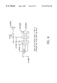
- FIG. 1 A A preferred embodiment of the invention is depicted in FIG. 1 A.
- Two distinct web paths are depicted by web 2 which follows the post-nip path and web 3 which follows the pre-nip path.
- Post-nip path means the web 2 contacts the nip roll 5 after contacting the ultrasonic equipment 1
- pre-nip path means the web 3 contacts the nip roll 5 before contacting the ultrasonic equipment 1 .
- Either construction internalliner or carrier
- pre-nip path can be run in either path (pre-nip or post nip).
- the post-nip path is preferred for both the interliner construction and the carrier construction.
- the webs employ path 2 in a preferred embodiment.
- the webs used in the post-nip path are preferably of carrier construction (see FIG. 2 ).
- the web 2 is fed off of a conventional unwind under controlled tension and is directed by one or more idle rollers 8 a , 8 b to the perforating station 18 .
- the perforating station 18 includes a driven pin roll 6 , a pin roll drive motor 7 , a nip roll 5 , air cylinders 4 , 12 , ultrasonic equipment 1 , 13 , 14 , 15 , a driven nip roll 10 , and a non-driver nip roll 16 .
- the pin roll 6 is knurled or engraved with a pattern of truncated conical projections, or pins 41 , 51 , 61 , 71 , 81 , 91 .
- the height and diameter of the pins will vary depending on the thickness of the film.
- the pins are generally about 0.025′′ high, with a diameter of the top of the pins preferably in the range of 0.005′′ to about 0.025′′.
- FIGS. 4, 5 , 6 , 7 , 8 , and 9 show preferred patterns of pin arrangements on the pin roll 6 , which mirror the perforation patterns created in the web 2 .
- the number of pins per square inch of pin roll 6 surface area will depend on the material used, and, for a thin film, the number of pins per square inch may range preferably from about 5 to about 500, and more preferably from 70 to 300, and most preferably between 110 to 230.
- the pins on the pin roll in the preferred embodiment, have a height greater than the height of the web as measured from the pin roll 6 toward the horn 1 .
- the pin roll 6 is preferably an unhardened material, such as steel, which may be coated with a wear resistant coating having release properties.
- the carrier construction web 2 (see FIG. 2) is oriented so that the adhesive layer is in contact with the pin roll 6 and the carrier paper is in contact with the ultrasonic equipment 1 .
- the release properties of the coating on the pin roll prevent the adhesive layer from becoming stuck to the pin roll 6 .
- the coating is, in a preferred embodiment, a chrome-carbide ceramic metal (cermet), applied to the pin roll 6 with a High Velocity Oxygen Fuel process, followed with a silicone post treatment and cure.
- the pin roll 6 is driven by a drive motor 7 .
- the drive motor 7 is driven by an electronic variable speed drive system (not shown).
- the drive motor 7 is preset to maintain a constant pin roll 6 speed.
- the web 2 exits one or more idle rollers 8 a , 8 b and wraps around the pin roll 6 , passing under the ultrasonic horn 1 .
- the ultrasonic horn is positioned so that the ultrasonic horn 1 is immediately adjacent to the pin roll 6 . There is no fixed gap between the ultrasonic horn 1 and the pin roll 6 , and no mechanical stop to prevent the horn 1 from contacting the pin roll 6 .
- the horn 1 does not come into direct contact with any adhesive on the material.
- the ultrasonic horn 1 may be a carbide tipped titanium horn.
- a booster 13 and converter 14 are used in connection with the ultrasonic horn 1 , forming the ultrasonic stack.
- Air actuator 15 is affixed to the ultrasonic stack. Air actuator 15 causes the ultrasonic horn 1 to fully contact one side of the web 2 , and the pin roll 6 to fully contact the other side of the web 2 . Air actuator 15 also causes the ultrasonic horn 1 to fully contact the pin roll 6 when the web 2 is not present.
- the air pressure in the air loaded actuator 15 and the amplitude of the ultrasonic generator can be varied 50-100%, from 2.5 bs/inch of width to 150 lbs/inch of width to generate the holes formed in the adhesive 21 and film or foam layer 22 of the carrier construction. These holes may be formed without completely penetrating the carrier paper 23 .
- the horn loads applied by air actuator 15 to the web are preferably from 20 lbs/inch of width to 60 lbs/inch of width.
- the ultrasonic stack is driven by a conventional ultrasonic generator.
- the ultrasonic equipment has an adjustable amplitude and a maximum power input of 2000 to 2500 watts, and operates at or near a frequency of 20 kHz, although other commercially available units could be used in the present application with operating ranges from 15 kHz (audible frequency) to 40 kHz, and other applications could use units with operating ranges up to 400 kHz.
- the maximum power and frequency may optionally be increased over these limits depending on equipment used.
- the ultrasonic horn preferably imparts a localized heating to soften and melt the material at the tip of the pins on the pin roll producing a pattern of holes which match the pin pattern on the pin roll.
- the need for a precise fixed gap between the horn 1 and pin roll 6 is eliminated by providing the air actuator 15 which controls the placement of the horn.
- the movement of the horn 1 toward or away from the pin roll 6 is controlled only by the air actuator 15 , and gravity in an embodiment wherein the horn 1 is vertical to the ground, and is not limited by a stop as in the prior art.
- the horn 1 is forced toward the pin roll 6 , and is in contact with the pin roll 6 when there is no material wound around the pin roll 6 .
- the horn 1 is forced, by both the air actuator 15 and gravity, into contact with the material.
- the force with which the horn 1 is forced onto the material is dependent on the type of material, and the perforation desired.
- Table I shows some examples of the types of materials used with the present invention, and the force with which they are pressed into contact with the horn 1 . Additionally, the horn 1 is controlled for amplitude and vibration, as well as force toward the material. Excessive horn force, amplitude, or vibration provides undesired stress to the system components. Thus, the horn is maintained to provide only enough force, amplitude, and vibration to provide the desired web porosity.
- the air actuator 15 discussed herein is exemplary only. Any type of actuator 15 known in the art, such as a hydraulic or spring actuator, may be used in the present invention to urge the horn toward the material. Additionally, because the force toward the material of the horn maintains a contact with the material, the present invention does not require any active variation of the gap, but rather maintains the contact through passive variations.
- Prior art runout may be manifested in cyclical variation in the size of the holes perforated in the web as the height of the gap varied within each revolution of the pin roll, unless the pin roll body, journals, bearings and bearing seats are precisely machined.
- the porosity in the prior art may increase during a continuous production resulting from the decrease in the gap brought about by the thermal expansion of the horn, since forced air cooling is not provided in the prior art.
- the horn 1 has a tendency to heat while web perforations are being created.
- an application of a forced stream of air to the tip of the horn 1 by an air stream generator 17 cools the horn.
- the air stream generator 17 is a fan or a compressed air device. This cooling prevents premature horn failure due to heat induced cracking of the horn. Additionally, cooling limits, and preferably prevents, the increase in air porosity with time from the start-up of the perforating system to the shut-down of the perforating system.
- the web 2 passes between the ultrasonic horn 1 and pin roll 6 , while conforming to the circumference of the pin roll 6 , and, while still conforming to the pin roll 6 , passes between the pin roll 6 and the nip roll 5 .
- the nip roll 5 may be a steel core covered with hard rubber or plastic of preferably 70 to 100 durometer, Shore A hardness scale.
- One or more air cylinders 4 is employed to load the nip roll 5 against the pin roll 6 .
- the nip roll 5 contacts the pin roll 6 tangentially between 15 and 345 degrees around the circumference of the pin roll from the horn 1 .
- the nip roll 5 nips the web against the pin roll 6 to prevent any slippage of the web 2 over the pin roll 6 .
- the nip roll 5 imparts a very smooth texture to carrier construction type webs.
- the film or foam layer 22 is ultimately placed on the bandage user's skin and the carrier paper 23 is removed, the smooth texture of the web 2 is noticeable to the touch.
- the web 2 passes through an exit nip station.
- the exit nip station includes a driven nip roll 10 and a non-driven nip roll 16 .
- Both rolls 10 , 16 may be formed of rubber, or one may be formed of steel.
- the driven nip roll 10 is formed of steel, the steel must be release coated. Release coatings are well known in the art.
- the driven nip roll 10 is driven by the pin roll drive motor 7 with a variable speed or drive transmission 11 .
- variable speed or drive transmission 11 may be adjusted via a hand wheel, providing a slight stretch or draw to the web 2 , thereby eliminating any slack in the web 2 between the pin roll 6 and the driven nip roll 10 .
- the preferred variable speed or drive transmission ratio is from about 1.01:1 to 2:1, and is dependent upon such factors as the material of the web 2 being perforated, the geometry of the pin pattern, and the desired amount of perforations.
- One or more air cylinders 12 pneumatically load the non-driven nip roll 16 against the driven nip roll 10 and prevent the web 2 from slipping around the driven nip roll 10 , in order to provide constant speed and uniform tension in the web 2 .
- Tension in the web 2 is isolated between the pin roll 6 and the rewind roll (not shown).
- the web 2 enters the rewind roll after passing between the driven nip roll 10 and the non-driven nip roll 16 .
- the rewind tension is made to decrease as the diameter of the web 2 on the rewind roll increases.
- the web employs path 3 .
- the web 3 is fed off a conventional unwind under controlled tension and is directed by idler roller 8 a to the perforating station 18 .
- the perforating station includes a driven pin roll 6 , a pin roll drive motor 7 , a nip roll 5 , air cylinders 4 and 12 , ultrasonic equipment 1 , 13 , 14 , 15 , a drive/nip roll 10 , and a non-driven nip roll 16 .
- the web exits one or more idle rollers 8 a and is wound around the nip roll 5 .
- the web 3 passes between the nip roll 5 and the pin roll 6 , causing an impression of the pin pattern in the web 3 , but preferably no holes are produced.
- the film or foam layer 31 is compressed, displaced or both at the top of each pin, causing a smaller thickness in the film or foam layer where the film or foam layer contacts the top of each pin, thereby requiring less ultrasonic energy to perforate the web 3 than a web 2 as described above.
- the perforating speed in the pre-nip path may be increased approximately twenty percent (20%) over the speed set for the web 2 in the post-nip path.
- the porosity will be approximately ten to twenty percent (10-20%) greater than that obtained in the web 2 in the postnip path. This increase can be seen in FIG. 10 for webs having foam layers.
- the web 3 After the web 3 wraps around the nip roll 5 , the web 3 conforms to the contour of the pin roll 6 circumference and passes between the pin roll 6 and the ultrasonic horn 1 .
- the ultrasonic horn 1 perforates the film or foam layer 31 .
- the web 3 exits from the pin roll 6 , and tension is set to separate the web 3 from the pin roll 6 .
- tension is set relatively high, resulting in little or no wrap of the web 2 on the pin roll 6 immediately following the contact point between the pin roll 6 and the ultrasonic horn 1 .
- the tension is set relatively low, such as 0.5 pli to 2.5 pli, resulting in a small amount of wrap of the web 3 on the pin roll 6 immediately after the ultrasonic horn 1 .
- the web 3 passes through the exit nip station in order to set the above mentioned tension.
- the perforation system is preferably for use by webs 2 , 3 having a width of up to six inches. This size web exiting the perforation system could be fed immediately to a single high-speed adhesive bandage maker upon exiting the perforation system.
- the perforation system has the advantages of low capital cost, quick installation and quick start up time.
- the production of perforated webs 2 , 3 can be increased by employing one or more ultrasonic systems across a wider web, for example 30 inches to 60 inches wide.
- Other processes, such as slitting, can be combined with ultrasonic perforation for savings in capital costs and production costs.
- the web ( 2 ) follows a similar path to that shown in FIG. 1 A.
- the web 2 is directed by an idle roller 8 a to the perforating station 18 , where the web 2 passes between one or more ultrasonic horns 1 and the pin roll 6 , the web 2 continues around the circumference of the pin roll 6 , passes between the pin roll 6 and the nip roll 5 , and is then directed by one or more pass rollers 8 c , 8 d to a tension sensing roller 9 .
- the ultrasonic horns 1 are aligned so that each perforate a separate and distinct width of the web 2 .
- Tension sensing roller 9 measures and controls the tension in the web 2 between the pin roll 6 and the driven exit nip roll 10 .
- the exit nip drive motor 11 is preferably electronically regulated.
- the exit nip drive motor 11 will preferably follow the speed of the pin roll drive motor 7 .
- the exit nip drive motor speed is responsive to the tension sensing roller 9 , in order to maintain tension on the web 2 .
- the web 2 upon exiting the driven exit nip roll 10 , is rewound onto a core, preferably cardboard, by a rewind of conventional design.
- the web 3 follows a similar path as that shown in FIG. 1 A.
- the web 3 is directed by one or more idle rollers 8 b , 8 c to the perforating station 18 , where the web 3 passes between the nip roll 5 and the pin roll 6 , impressing the pin pattern into the web 3 .
- the web 3 winds around the circumference of the pin roll 6 and then passes between the ultrasonic horn 1 and the pin roll 6 , where it is perforated by one or more ultrasonic horns 1 .
- the ultrasonic horns 1 are aligned so that each perforate a separate and distinct width of the web 3 .
- the web 3 then separates from the pin roll 6 , passes around pass roller 8 d , and wraps around tension sensing roller 9 .
- Tension sensing roller 9 measures and controls the tension in the web 3 between the pin roll 6 and the driven exit nip roll 10 .
- the exit nip drive motor 11 is preferably electronically regulated.
- FIG. 1B illustrates an embodiment of the present invention that includes two or more ultrasonic horns 1 in series.
- This embodiment offers increased throughput where each horn maintains the same energy level as is used in an embodiment including only one horn 1 , and offers a decrease in horn energy necessary to maintain the same throughput as in an embodiment including only one horn 1 .
- the embodiment of FIG. 1B offers an increase in throughput of up to 20%. For example, using a carrier PVC web, a speed of 200 ft/min can be achieved using one horn 1 , with a target porosity of 30 cfm/sq.ft.
- a throughput of 240 ft/min can be achieved, at the same porosity, using at least two horns 1 .
- throughput speed
- a foam web at the porosity of 30 cfm/sq.ft would have a throughput of 60-70 ft/min using one horn, but would still display the same 20% throughput increase in an embodiment including multiple horns 1 .
- a corresponding increase in the circumference of the pin roll may be required to accommodate the additional horns 1 .
- the perforation system may further include a closed loop temperature control system.
- a temperature sensor would be mounted on or in the ultrasonic horn 1 , and the temperature of the horn would be input to a controller.
- the temperature sensor may be an infrared non-contact temperature sensor.
- the controller would control the air flow from the air stream generator 17 onto the ultrasonic horn 1 in order to maintain a pre-determined set temperature of the ultrasonic horn 1 . In this manner, the ultrasonic horn 1 will not be heated and will not cause a variation in the position of the ultrasonic horn 1 relative to the pin roll 6 .
- the closed loop system allows the horn to heat up to temperature, and then maintains an even temperature, thereby insuring a more narrow porosity range throughout a production run.
- FIG. 10 displays the air permeability, or porosity versus the pin roll speed for the ultrasonic perforation system. It is evident from the Figure that there is an increase in porosity for all given pin roll speeds where a pre-nip is used, versus an embodiment not using a prenip.
- FIG. 11 displays the air permeability, or porosity, of material resulting from the use of the nipped and unnipped pin roll. It is evident from the Figure that there is an increase in air permeability where a nipped pin roll is used, versus an embodiment including an unnipped pin roll. FIG. 11 shows the increase in porosity of a interlined film when the pre-nip path 3 is employed versus when the web 2 does not contact the nip roll 5 before the ultrasonic horn 1 (the post-nip path).
- FIG. 12 displays the air permeability (or porosity) of material resulting from the use of the open nip and the closed nip.
- open nip means the nip roll does not contact the pin roll
- closed nip means the nip roll contacts the pin roll.
- FIG. 12 illustrates the increase in speed at which a interliner film can be run in a pre-nip path to obtain the same porosity as a slower speed web in the post-nip path 2 .
Abstract
Description
Claims (67)
Priority Applications (10)
| Application Number | Priority Date | Filing Date | Title |
|---|---|---|---|
| US09/471,976 US6277224B1 (en) | 1999-12-23 | 1999-12-23 | Ultrasonic perforator and a method for performing an ultrasonic perforation |
| BRPI0007359-8A BR0007359B1 (en) | 1999-12-23 | 2000-12-21 | ultrasonic drilling is a process for performing ultrasonic drilling. |
| CA002329383A CA2329383C (en) | 1999-12-23 | 2000-12-21 | An ultrasonic perforator and a method for performing an ultrasonic perforation |
| ZA200007807A ZA200007807B (en) | 1999-12-23 | 2000-12-21 | An ultrasonic perforator and a method for performing ultrasonic perforation. |
| AU72513/00A AU775287B2 (en) | 1999-12-23 | 2000-12-22 | An ultrasonic perforator and a method for performing an ultrasonic perforation |
| EP00311666A EP1112823B1 (en) | 1999-12-23 | 2000-12-22 | An ultrasonic perforator and a method for performing an ultrasonic perforation |
| JP2000391290A JP4767407B2 (en) | 1999-12-23 | 2000-12-22 | Ultrasonic drilling apparatus and ultrasonic drilling method |
| DE60026807T DE60026807T2 (en) | 1999-12-23 | 2000-12-22 | Device and method for perforating by ultrasound |
| CNB001372718A CN1321784C (en) | 1999-12-23 | 2000-12-22 | Supersonic boring machine and method thereof |
| MXPA01000108A MXPA01000108A (en) | 1999-12-23 | 2001-01-08 | Ultrasonic perforator and a method for performing an ultrasonic perforation. |
Applications Claiming Priority (1)
| Application Number | Priority Date | Filing Date | Title |
|---|---|---|---|
| US09/471,976 US6277224B1 (en) | 1999-12-23 | 1999-12-23 | Ultrasonic perforator and a method for performing an ultrasonic perforation |
Publications (1)
| Publication Number | Publication Date |
|---|---|
| US6277224B1 true US6277224B1 (en) | 2001-08-21 |
Family
ID=23873736
Family Applications (1)
| Application Number | Title | Priority Date | Filing Date |
|---|---|---|---|
| US09/471,976 Expired - Lifetime US6277224B1 (en) | 1999-12-23 | 1999-12-23 | Ultrasonic perforator and a method for performing an ultrasonic perforation |
Country Status (10)
| Country | Link |
|---|---|
| US (1) | US6277224B1 (en) |
| EP (1) | EP1112823B1 (en) |
| JP (1) | JP4767407B2 (en) |
| CN (1) | CN1321784C (en) |
| AU (1) | AU775287B2 (en) |
| BR (1) | BR0007359B1 (en) |
| CA (1) | CA2329383C (en) |
| DE (1) | DE60026807T2 (en) |
| MX (1) | MXPA01000108A (en) |
| ZA (1) | ZA200007807B (en) |
Cited By (20)
| Publication number | Priority date | Publication date | Assignee | Title |
|---|---|---|---|---|
| US20020176730A1 (en) * | 2001-05-14 | 2002-11-28 | Frederick Bleckmann | Method and apparatus for production of labels |
| US20030135187A1 (en) * | 2000-05-30 | 2003-07-17 | Klemp Walter V. | Disposable absorbent garment such as a diaper or training pants and a process of making the same |
| US6645330B2 (en) | 2002-01-03 | 2003-11-11 | Paragon Trade Brands, Inc. | Method of making disposable absorbent article having graphics using ultrasonic thermal imaging |
| US20040084995A1 (en) * | 2002-11-04 | 2004-05-06 | Stegelmann Norman R. | Ultrasonic horn assembly stack component connector |
| US20040216830A1 (en) * | 2003-04-30 | 2004-11-04 | Kimberly-Clark Worldwide, Inc. | Apparatus and method for mechanically bonding and cutting an article |
| US20050087282A1 (en) * | 2003-10-28 | 2005-04-28 | Streicher James G. | Non-invasive tear mechanism for flexible packaging and apparatus |
| US6942404B1 (en) * | 2001-12-17 | 2005-09-13 | Michael Demarchi | Marker tubing processing methods and apparatus |
| US20050224168A1 (en) * | 2002-02-05 | 2005-10-13 | Hans-Willi Mainz | Method and device for improving adhesion of the individual layers of a composite material |
| US20060243367A1 (en) * | 2005-04-27 | 2006-11-02 | Engelhart Darin A | Multi-roll bonding and aperturing |
| US20090205471A1 (en) * | 2008-02-14 | 2009-08-20 | Boyer Machine Inc. | Film perforation apparatus |
| US20090224443A1 (en) * | 2008-03-05 | 2009-09-10 | Rundquist Victor F | Niobium as a protective barrier in molten metals |
| US20110229688A1 (en) * | 2008-11-28 | 2011-09-22 | Brightwake Limited | Perforation of laminated materials, laminate comprising a perforated layer of hydrophobic gel and an imperforate substrate, wound dressing |
| US8574336B2 (en) | 2010-04-09 | 2013-11-05 | Southwire Company | Ultrasonic degassing of molten metals |
| US8652397B2 (en) | 2010-04-09 | 2014-02-18 | Southwire Company | Ultrasonic device with integrated gas delivery system |
| US9486553B2 (en) | 2009-07-16 | 2016-11-08 | Brightwake Limited | Method |
| US9528167B2 (en) | 2013-11-18 | 2016-12-27 | Southwire Company, Llc | Ultrasonic probes with gas outlets for degassing of molten metals |
| CN108081357A (en) * | 2017-12-27 | 2018-05-29 | 宁波雯泽纺织品有限公司 | Cloth tensioning apparatus |
| US10233515B1 (en) | 2015-08-14 | 2019-03-19 | Southwire Company, Llc | Metal treatment station for use with ultrasonic degassing system |
| CN113423368A (en) * | 2019-02-26 | 2021-09-21 | 墨尼克医疗用品有限公司 | Method of introducing perforations into a laminate comprising a silicone gel |
| EP2712312B1 (en) | 2011-05-17 | 2023-01-11 | Smith & Nephew plc | Negative-pressure wound treatment apparatus |
Families Citing this family (20)
| Publication number | Priority date | Publication date | Assignee | Title |
|---|---|---|---|---|
| US20030131919A1 (en) * | 2001-12-28 | 2003-07-17 | King Timothy James | Method for simultaneously imprinting a pattern and bonding cellulose webs using ultrasonic energy |
| DE10202333B4 (en) * | 2002-01-23 | 2006-04-06 | Nordenia Deutschland Gronau Gmbh | Process for producing an elastic, air-permeable composite film |
| US6773527B2 (en) | 2002-04-01 | 2004-08-10 | Kimberly-Clark Worldwide, Inc. | Method for obtaining improved ultrasonic bond strength |
| SE530256C2 (en) * | 2005-12-16 | 2008-04-15 | Moelnlycke Health Care Ab | Method for making holes in heat-meltable materials |
| EP1849569B2 (en) | 2006-04-26 | 2020-12-09 | Herrmann Ultraschalltechnik GmbH & Co. KG | Device for machining workpieces using ultrasound and method for operating such a device |
| US9132225B2 (en) | 2009-01-15 | 2015-09-15 | Brightwake Limited | Cardiopulmonary bypass circuit including a filtration device |
| CN102794645A (en) * | 2011-05-26 | 2012-11-28 | 李景珠 | Numerical control pinhole machining device |
| CN102248775A (en) * | 2011-06-01 | 2011-11-23 | 江苏万乐复合材料有限公司 | Low-melting point polyethylene (PE) film online printing perforating machine |
| WO2014206452A1 (en) * | 2013-06-26 | 2014-12-31 | Knauf Gips Kg | Gypsum plasterboard production plant and method for producing a gypsum plasterboard |
| US10351377B2 (en) * | 2015-08-03 | 2019-07-16 | Elsner Engineering Works, Inc. | Ultrasonic roll tail closure of non-woven web material method and apparatus |
| CN105666579A (en) * | 2016-01-25 | 2016-06-15 | 李理 | Electric heating needle for punching holes in rubber strips |
| CN105568553B (en) * | 2016-02-29 | 2018-10-02 | 嘉兴南华无纺材料有限公司 | Improved non-woven fabric production equipment |
| CN105671842B (en) * | 2016-02-29 | 2018-03-20 | 嘉兴南华无纺材料有限公司 | The pressing device of the production equipment of non-woven fabrics |
| DE102017119279A1 (en) * | 2017-08-23 | 2019-02-28 | Herrmann Ultraschalltechnik Gmbh & Co. Kg | Method for cutting a rubber sheet |
| CN109822668A (en) * | 2018-11-23 | 2019-05-31 | 佛山市稳格家居用品有限公司 | A kind of synthetic leather perforating device and drilling technology |
| EP3930975A1 (en) * | 2019-02-26 | 2022-01-05 | Mölnlycke Health Care AB | Device and process for introducing perforations into laminates |
| CN109940687A (en) * | 2019-04-03 | 2019-06-28 | 上海泽平机械设备有限公司 | A kind of Silica hydrogel ultrasonic drilling machine |
| CN112406251A (en) * | 2019-08-20 | 2021-02-26 | 杭州特种纸业有限公司 | Ultrasonic wave composite perforating machine |
| CN111215310A (en) * | 2020-01-13 | 2020-06-02 | 杭州电子科技大学 | Multi-gear ultrasonic generation control acquisition electric appliance cabinet |
| CN113524693B (en) * | 2021-07-16 | 2023-01-13 | 吉祥三宝高科纺织有限公司 | Ultrasonic low-damage point-like automatic compound mechanism of protective mask |
Citations (5)
| Publication number | Priority date | Publication date | Assignee | Title |
|---|---|---|---|---|
| US4747895A (en) * | 1986-08-20 | 1988-05-31 | American White Cross Laboratories, Inc. | Continuous ultrasonic perforating system and method |
| US5230761A (en) * | 1984-05-21 | 1993-07-27 | Qst Industries, Inc. | Waistband interlining with thin edges and its ultrasonic formation |
| US5735984A (en) * | 1994-11-08 | 1998-04-07 | Minnesota Mining And Manufacturing Company | Method of aperturing thin sheet materials |
| US5879494A (en) * | 1996-09-23 | 1999-03-09 | Minnesota Mining And Manufacturing Company | Method of aperturing thin sheet materials |
| US5879493A (en) * | 1995-04-03 | 1999-03-09 | Minnesota Mining And Manufacturing Company | Viral resistant seam for protective apparel, and method of manufacturing same |
Family Cites Families (11)
| Publication number | Priority date | Publication date | Assignee | Title |
|---|---|---|---|---|
| FR2313186A1 (en) * | 1975-03-13 | 1976-12-31 | Calemard Station Service Texti | DEVICE APPLYING ULTRA-SONIC EFFECTS TO OPERATIONS SUCH AS CUTTING, WELDING AND OTHERS, PERFORMED ON TEXTILE OR SHEET ARTICLES, WOVEN OR NOT, PARTLY OR TOTALLY THERMOFUSIBLE |
| GB2208622B (en) * | 1984-12-03 | 1989-09-20 | Asahi Chemical Ind | Tool usable for production of an easily openable tightly sealed bag |
| JPS61260997A (en) * | 1985-05-16 | 1986-11-19 | 株式会社井上ジャパックス研究所 | Deburring device |
| JPH04109242A (en) * | 1990-08-30 | 1992-04-10 | Konica Corp | Cutting device for photographic telemp |
| EP0540495A1 (en) * | 1991-10-30 | 1993-05-05 | GFM Gesellschaft für Fertigungstechnik und Maschinenbau Aktiengesellschaft | Method of cutting workpieces made from fibre reinforced plastic |
| DE4206584C2 (en) * | 1992-03-03 | 1994-03-10 | Fraunhofer Ges Forschung | Device and method for connecting two components by means of ultrasound |
| JPH07156135A (en) * | 1993-12-02 | 1995-06-20 | Nikon Corp | Method and apparatus for machining hard an brittle material |
| SE508245C2 (en) * | 1994-12-30 | 1998-09-21 | Moelnlycke Ab | Method and apparatus for perforating a web of material |
| JPH1177596A (en) * | 1997-09-03 | 1999-03-23 | Mitsuo Fujisawa | Ultrasonic machining device for sheet material |
| DE19753740C1 (en) * | 1997-12-04 | 1999-07-15 | Herrmann Ultraschalltechnik | Device for processing a material web |
| JP2000084895A (en) * | 1998-09-09 | 2000-03-28 | Bridgestone Corp | Sheet cutting tool and sheet winding device |
-
1999
- 1999-12-23 US US09/471,976 patent/US6277224B1/en not_active Expired - Lifetime
-
2000
- 2000-12-21 CA CA002329383A patent/CA2329383C/en not_active Expired - Lifetime
- 2000-12-21 BR BRPI0007359-8A patent/BR0007359B1/en not_active IP Right Cessation
- 2000-12-21 ZA ZA200007807A patent/ZA200007807B/en unknown
- 2000-12-22 EP EP00311666A patent/EP1112823B1/en not_active Expired - Lifetime
- 2000-12-22 CN CNB001372718A patent/CN1321784C/en not_active Expired - Lifetime
- 2000-12-22 DE DE60026807T patent/DE60026807T2/en not_active Expired - Lifetime
- 2000-12-22 AU AU72513/00A patent/AU775287B2/en not_active Expired
- 2000-12-22 JP JP2000391290A patent/JP4767407B2/en not_active Expired - Lifetime
-
2001
- 2001-01-08 MX MXPA01000108A patent/MXPA01000108A/en active IP Right Grant
Patent Citations (5)
| Publication number | Priority date | Publication date | Assignee | Title |
|---|---|---|---|---|
| US5230761A (en) * | 1984-05-21 | 1993-07-27 | Qst Industries, Inc. | Waistband interlining with thin edges and its ultrasonic formation |
| US4747895A (en) * | 1986-08-20 | 1988-05-31 | American White Cross Laboratories, Inc. | Continuous ultrasonic perforating system and method |
| US5735984A (en) * | 1994-11-08 | 1998-04-07 | Minnesota Mining And Manufacturing Company | Method of aperturing thin sheet materials |
| US5879493A (en) * | 1995-04-03 | 1999-03-09 | Minnesota Mining And Manufacturing Company | Viral resistant seam for protective apparel, and method of manufacturing same |
| US5879494A (en) * | 1996-09-23 | 1999-03-09 | Minnesota Mining And Manufacturing Company | Method of aperturing thin sheet materials |
Cited By (41)
| Publication number | Priority date | Publication date | Assignee | Title |
|---|---|---|---|---|
| US20030135187A1 (en) * | 2000-05-30 | 2003-07-17 | Klemp Walter V. | Disposable absorbent garment such as a diaper or training pants and a process of making the same |
| US6994761B2 (en) * | 2000-05-30 | 2006-02-07 | Fameccanica Data S.P.A. | Disposable absorbent garment such as a diaper or training pants and a process of making the same |
| US20020176730A1 (en) * | 2001-05-14 | 2002-11-28 | Frederick Bleckmann | Method and apparatus for production of labels |
| US6830639B2 (en) * | 2001-05-14 | 2004-12-14 | Pittsfield Weaving Co., Inc. | Method and apparatus for producing folded labels having rounded corners |
| US6942404B1 (en) * | 2001-12-17 | 2005-09-13 | Michael Demarchi | Marker tubing processing methods and apparatus |
| US6645330B2 (en) | 2002-01-03 | 2003-11-11 | Paragon Trade Brands, Inc. | Method of making disposable absorbent article having graphics using ultrasonic thermal imaging |
| US20050224168A1 (en) * | 2002-02-05 | 2005-10-13 | Hans-Willi Mainz | Method and device for improving adhesion of the individual layers of a composite material |
| US20070194661A1 (en) * | 2002-11-04 | 2007-08-23 | Kimberly-Clark Worldwide, Inc. | Ultrasonic Horn Assembly Stack Component Connector Having Threadless Segment |
| US20050110370A1 (en) * | 2002-11-04 | 2005-05-26 | Kimberly-Clark Worldwide, Inc. | Ultrasonic horn assembly stack component connector |
| US6841921B2 (en) * | 2002-11-04 | 2005-01-11 | Kimberly-Clark Worldwide, Inc. | Ultrasonic horn assembly stack component connector |
| US7514846B2 (en) | 2002-11-04 | 2009-04-07 | Kimberly-Clark Worldwide, Inc. | Ultrasonic horn assembly stack component connector having threadless segment |
| US20040084995A1 (en) * | 2002-11-04 | 2004-05-06 | Stegelmann Norman R. | Ultrasonic horn assembly stack component connector |
| US20040216830A1 (en) * | 2003-04-30 | 2004-11-04 | Kimberly-Clark Worldwide, Inc. | Apparatus and method for mechanically bonding and cutting an article |
| US7204899B2 (en) * | 2003-04-30 | 2007-04-17 | Kimberly-Clark Worldwide, Inc. | Apparatus and method for mechanically bonding and cutting an article |
| US20070144678A1 (en) * | 2003-04-30 | 2007-06-28 | Kimberly-Clark Worldwide, Inc. | Apparatus for mechanically bonding and cutting an article |
| US7341084B2 (en) | 2003-04-30 | 2008-03-11 | Kimberly-Clark Worldwide, Inc. | Apparatus for mechanically bonding and cutting an article |
| US7229512B2 (en) * | 2003-10-28 | 2007-06-12 | Streicher James G | Non-invasive tear mechanism for flexible packaging and apparatus |
| US20050087282A1 (en) * | 2003-10-28 | 2005-04-28 | Streicher James G. | Non-invasive tear mechanism for flexible packaging and apparatus |
| US20060243367A1 (en) * | 2005-04-27 | 2006-11-02 | Engelhart Darin A | Multi-roll bonding and aperturing |
| US7323072B2 (en) * | 2005-04-27 | 2008-01-29 | Kimberly-Clark Worldwide, Inc. | Multi-roll bonding and aperturing |
| US20090205471A1 (en) * | 2008-02-14 | 2009-08-20 | Boyer Machine Inc. | Film perforation apparatus |
| US20090224443A1 (en) * | 2008-03-05 | 2009-09-10 | Rundquist Victor F | Niobium as a protective barrier in molten metals |
| US8844897B2 (en) | 2008-03-05 | 2014-09-30 | Southwire Company, Llc | Niobium as a protective barrier in molten metals |
| US9327347B2 (en) | 2008-03-05 | 2016-05-03 | Southwire Company, Llc | Niobium as a protective barrier in molten metals |
| US20110229688A1 (en) * | 2008-11-28 | 2011-09-22 | Brightwake Limited | Perforation of laminated materials, laminate comprising a perforated layer of hydrophobic gel and an imperforate substrate, wound dressing |
| EP2382069A1 (en) | 2008-11-28 | 2011-11-02 | Brightwake Limited | Perforation of laminated materials, laminate comprising a perforated layer of hydrophobic gel and an imperforate substrate, wound dressing |
| EP2382069B1 (en) * | 2008-11-28 | 2017-08-09 | Brightwake Limited | Perforation of laminated materials |
| US9486553B2 (en) | 2009-07-16 | 2016-11-08 | Brightwake Limited | Method |
| US9617617B2 (en) | 2010-04-09 | 2017-04-11 | Southwire Company, Llc | Ultrasonic degassing of molten metals |
| US9382598B2 (en) | 2010-04-09 | 2016-07-05 | Southwire Company, Llc | Ultrasonic device with integrated gas delivery system |
| US8652397B2 (en) | 2010-04-09 | 2014-02-18 | Southwire Company | Ultrasonic device with integrated gas delivery system |
| US8574336B2 (en) | 2010-04-09 | 2013-11-05 | Southwire Company | Ultrasonic degassing of molten metals |
| US10640846B2 (en) | 2010-04-09 | 2020-05-05 | Southwire Company, Llc | Ultrasonic degassing of molten metals |
| EP2712312B1 (en) | 2011-05-17 | 2023-01-11 | Smith & Nephew plc | Negative-pressure wound treatment apparatus |
| US9528167B2 (en) | 2013-11-18 | 2016-12-27 | Southwire Company, Llc | Ultrasonic probes with gas outlets for degassing of molten metals |
| US10316387B2 (en) | 2013-11-18 | 2019-06-11 | Southwire Company, Llc | Ultrasonic probes with gas outlets for degassing of molten metals |
| US10233515B1 (en) | 2015-08-14 | 2019-03-19 | Southwire Company, Llc | Metal treatment station for use with ultrasonic degassing system |
| CN108081357A (en) * | 2017-12-27 | 2018-05-29 | 宁波雯泽纺织品有限公司 | Cloth tensioning apparatus |
| CN108081357B (en) * | 2017-12-27 | 2019-06-21 | 宁波雯泽纺织品有限公司 | Cloth tensioning apparatus |
| CN113423368A (en) * | 2019-02-26 | 2021-09-21 | 墨尼克医疗用品有限公司 | Method of introducing perforations into a laminate comprising a silicone gel |
| CN113423368B (en) * | 2019-02-26 | 2023-01-06 | 墨尼克医疗用品有限公司 | Method of introducing perforations into a laminate comprising a silicone gel |
Also Published As
| Publication number | Publication date |
|---|---|
| DE60026807D1 (en) | 2006-05-11 |
| AU775287B2 (en) | 2004-07-29 |
| DE60026807T2 (en) | 2007-03-29 |
| BR0007359A (en) | 2002-04-23 |
| ZA200007807B (en) | 2002-06-21 |
| EP1112823B1 (en) | 2006-03-22 |
| JP4767407B2 (en) | 2011-09-07 |
| MXPA01000108A (en) | 2002-10-23 |
| CA2329383C (en) | 2009-12-08 |
| CN1337299A (en) | 2002-02-27 |
| CA2329383A1 (en) | 2001-06-23 |
| AU7251300A (en) | 2001-06-28 |
| CN1321784C (en) | 2007-06-20 |
| BR0007359B1 (en) | 2008-11-18 |
| JP2001246597A (en) | 2001-09-11 |
| EP1112823A2 (en) | 2001-07-04 |
| EP1112823A3 (en) | 2003-05-14 |
Similar Documents
| Publication | Publication Date | Title |
|---|---|---|
| US6277224B1 (en) | Ultrasonic perforator and a method for performing an ultrasonic perforation | |
| US4854984A (en) | Dynamic mechanical bonding method and apparatus | |
| US4919738A (en) | Dynamic mechanical bonding method and apparatus | |
| EP0235790B1 (en) | Laminating device with paper or laminate tension control | |
| US4743334A (en) | Double sided laminating machine | |
| US6120629A (en) | Ultrasonic processing | |
| JPH0698597B2 (en) | Continuous ultrasonic perforation apparatus and method | |
| JPS5825577B2 (en) | Method and equipment for embossing and drilling | |
| US4786353A (en) | Laminating method and apparatus with extensible web width control | |
| US6902394B2 (en) | Apparatus for aiding the removal of an adhesively coated web from a rotating roll | |
| US20100032867A1 (en) | Method and apparatus for embossing non woven webs | |
| RU2488487C1 (en) | Method and system for producing perforated coiled material | |
| JPH06218899A (en) | Laminating method of air permeable sheet-like material | |
| US3582430A (en) | Method and apparatus for bonding foam plastic to a backing | |
| CA1086625A (en) | Printed textile web material | |
| JPH03150162A (en) | In-line sheet-laminating device of hot melt type | |
| JPH03101864A (en) | Extrusion laminating method | |
| CN116323152A (en) | Extrusion perforation system and method | |
| JP2005113223A (en) | Method and apparatus for heating metal foil | |
| JP2007301908A (en) | Apparatus for attaching backing liner to metal plate |
Legal Events
| Date | Code | Title | Description |
|---|---|---|---|
| FPAY | Fee payment |
Year of fee payment: 4 |
|
| REMI | Maintenance fee reminder mailed | ||
| STCF | Information on status: patent grant |
Free format text: PATENTED CASE |
|
| FP | Expired due to failure to pay maintenance fee |
Effective date: 20050821 |
|
| FPAY | Fee payment |
Year of fee payment: 8 |
|
| FPAY | Fee payment |
Year of fee payment: 12 |
|
| AS | Assignment |
Owner name: JOHNSON & JOHNSON CONSUMER COMPANIES, INC., NEW JE Free format text: ASSIGNMENT OF ASSIGNORS INTEREST;ASSIGNORS:MUESCH, EDWARD;ADAMS, CHARLIE LEE;MEIZANIS, JAMES;SIGNING DATES FROM 20131205 TO 20131213;REEL/FRAME:031804/0818 |
|
| AS | Assignment |
Owner name: JOHNSON & JOHNSON CONSUMER COMPANIES, LLC, DELAWARE Free format text: MERGER;ASSIGNOR:JOHNSON & JOHNSON CONSUMER COMPANIES, INC.;REEL/FRAME:036043/0978 Effective date: 20150623 Owner name: JOHNSON & JOHNSON CONSUMER INC, NEW JERSEY Free format text: MERGER AND CHANGE OF NAME;ASSIGNORS:JOHNSON & JOHNSON CONSUMER COMPANIES, LLC;JOHNSON & JOHNSON CONSUMER INC.;REEL/FRAME:036041/0605 Effective date: 20150623 Owner name: JOHNSON & JOHNSON CONSUMER COMPANIES, LLC, DELAWAR Free format text: MERGER;ASSIGNOR:JOHNSON & JOHNSON CONSUMER COMPANIES, INC.;REEL/FRAME:036043/0978 Effective date: 20150623 |
|
| AS | Assignment |
Owner name: JOHNSON & JOHNSON CONSUMER INC., NEW JERSEY Free format text: CORRECTIVE ASSIGNMENT TO CORRECT THE MERGED ENTITY' NEW NAME PREVIOUSLY RECORDED AT REEL: 036041 FRAME: 0605. ASSIGNOR(S) HEREBY CONFIRMS THE MERGER & CHANGE OF NAME;ASSIGNOR:JOHNSON & JOHNSON CONSUMER COMPANIES, LLC;REEL/FRAME:036143/0449 Effective date: 20150623 |