US6279447B1 - Method for the manufacture of gun ammunition having elongated projectile and a cartridge produced thereby - Google Patents
Method for the manufacture of gun ammunition having elongated projectile and a cartridge produced thereby Download PDFInfo
- Publication number
- US6279447B1 US6279447B1 US09/166,345 US16634598A US6279447B1 US 6279447 B1 US6279447 B1 US 6279447B1 US 16634598 A US16634598 A US 16634598A US 6279447 B1 US6279447 B1 US 6279447B1
- Authority
- US
- United States
- Prior art keywords
- case
- projectile
- gun
- powder
- gun powder
- Prior art date
- Legal status (The legal status is an assumption and is not a legal conclusion. Google has not performed a legal analysis and makes no representation as to the accuracy of the status listed.)
- Expired - Lifetime
Links
- 238000000034 method Methods 0.000 title claims abstract description 14
- 238000004519 manufacturing process Methods 0.000 title claims abstract description 9
- 239000003721 gunpowder Substances 0.000 claims abstract description 51
- 239000000843 powder Substances 0.000 claims description 17
- 230000005484 gravity Effects 0.000 claims description 5
- WFKWXMTUELFFGS-UHFFFAOYSA-N tungsten Chemical compound [W] WFKWXMTUELFFGS-UHFFFAOYSA-N 0.000 claims description 5
- 229910052721 tungsten Inorganic materials 0.000 claims description 4
- 239000010937 tungsten Substances 0.000 claims description 4
- ATJFFYVFTNAWJD-UHFFFAOYSA-N Tin Chemical compound [Sn] ATJFFYVFTNAWJD-UHFFFAOYSA-N 0.000 claims description 2
- 239000000203 mixture Substances 0.000 claims description 2
- 229910052751 metal Inorganic materials 0.000 claims 4
- 239000002184 metal Substances 0.000 claims 4
- 238000002788 crimping Methods 0.000 claims 1
- WABPQHHGFIMREM-UHFFFAOYSA-N lead(0) Chemical compound [Pb] WABPQHHGFIMREM-UHFFFAOYSA-N 0.000 claims 1
- 238000003780 insertion Methods 0.000 abstract description 4
- 230000037431 insertion Effects 0.000 abstract description 4
- 230000002939 deleterious effect Effects 0.000 abstract 1
- 239000002245 particle Substances 0.000 description 10
- 238000010304 firing Methods 0.000 description 9
- 230000000694 effects Effects 0.000 description 5
- 239000000463 material Substances 0.000 description 2
- 229910001369 Brass Inorganic materials 0.000 description 1
- 238000010276 construction Methods 0.000 description 1
- 238000007796 conventional method Methods 0.000 description 1
- 230000006378 damage Effects 0.000 description 1
- 238000011161 development Methods 0.000 description 1
- 238000006073 displacement reaction Methods 0.000 description 1
- 229910001385 heavy metal Inorganic materials 0.000 description 1
- 238000012360 testing method Methods 0.000 description 1
- 239000011800 void material Substances 0.000 description 1
Images

Classifications
-
- F—MECHANICAL ENGINEERING; LIGHTING; HEATING; WEAPONS; BLASTING
- F42—AMMUNITION; BLASTING
- F42B—EXPLOSIVE CHARGES, e.g. FOR BLASTING, FIREWORKS, AMMUNITION
- F42B33/00—Manufacture of ammunition; Dismantling of ammunition; Apparatus therefor
- F42B33/02—Filling cartridges, missiles, or fuzes; Inserting propellant or explosive charges
- F42B33/025—Filling cartridges, missiles, or fuzes; Inserting propellant or explosive charges by compacting
-
- F—MECHANICAL ENGINEERING; LIGHTING; HEATING; WEAPONS; BLASTING
- F42—AMMUNITION; BLASTING
- F42B—EXPLOSIVE CHARGES, e.g. FOR BLASTING, FIREWORKS, AMMUNITION
- F42B33/00—Manufacture of ammunition; Dismantling of ammunition; Apparatus therefor
- F42B33/001—Devices or processes for assembling ammunition, cartridges or cartridge elements from parts
-
- F—MECHANICAL ENGINEERING; LIGHTING; HEATING; WEAPONS; BLASTING
- F42—AMMUNITION; BLASTING
- F42B—EXPLOSIVE CHARGES, e.g. FOR BLASTING, FIREWORKS, AMMUNITION
- F42B33/00—Manufacture of ammunition; Dismantling of ammunition; Apparatus therefor
- F42B33/02—Filling cartridges, missiles, or fuzes; Inserting propellant or explosive charges
- F42B33/0207—Processes for loading or filling propulsive or explosive charges in containers
Definitions
- This invention relates to the manufacture of gun ammunition (cartridges) which include a case having a closed end which houses a primer and an open end, gun powder disposed within the case, and a projectile secured in the open end of the case.
- Gun ammunition known also as cartridges, are of standardized dimensions for a given caliber gun. These standards are set by the Sporting Arms and Ammunition Manufacturers Institute (SAAMI).
- SAAMI Sporting Arms and Ammunition Manufacturers Institute
- OAL overall length of the cartridge is critical to the successful operation of the mechanism which feeds the cartridge from a magazine into the breech of the gun.
- maximization of impact energy of the projectile upon striking a target dictates that the projectile be of maximum weight.
- Any given projectile desirably travels from the gun muzzle to a target with the longitudinal centerline of the projectile aligned with the trajectory of the projectile, that is, the projectile exhibits stability of flight from the gun muzzle to its target.
- a projectile can be overstabilized or understabilized.
- spin effects created by firing the projectile from a rifled gun barrel precession (i.e. yaw about the center of gravity of the projectile), nutation (another movement inside the precession), and wind effect.
- the wind effect may be reduced toward a minimum by making the projectile heavier, such as by fabricating the projectile from a heavy metal such as tungsten.
- Increasing the length of the projectile also can increase the overall weight of the projectile (for a given caliber).
- the size (geometry), including the length of a cartridge case is established by the standards set in the industry so that any given caliber ammunition cartridge will be received within the firing chamber of any gun of such given caliber.
- the only place the extra length of projectile can go is within the case.
- the “extra” length of the projectile takes up space within the interior of the case which normally would be available for gun powder.
- the gun powder be chosen to accommodate the heavier projectile, both from the standpoint of the increased weight of the projectile and the fact that there is less volume within the case for gun powder. In any event, it becomes desirable that there be a maximum amount of gun powder loaded into the case (along with the trailing end of the projectile).
- annular space between the outer surface of the projectile and the inner surface of the case.
- this annular space is devoid of gun powder. This factor exacerbates the problems of choice of the type of gun powder and the volume of gun powder which can be added to the case.
- the individual particles of a commercial gun powder are deliberately sized and of a geometry as will produce a given result when ignited within a cartridge case.
- the individual particles of a given gun powder may be flakes, balls, non-perforated grain (cylindrical), single perforated grain (tubular), or multi-perforated grain, for example.
- Each shape is designed to provide a given burn rate for each powder particle, which in turn develops a collective distinctive gas pressure curve for each type of gun powder. This burn rate and resulting gas pressure curve are critical for developing a given muzzle velocity for a given projectile from a gun. Any destruction, even partial, of the shape of particles of the gun powder will alter the gas pressure curve of a given charge of the gun powder.
- the present invention has as an object the provision of a method for the manufacture of gun ammunition cartridges wherein there is maximization of the permissible length of the projectile of each cartridge and full utilization of that interior volume of the case which is not occupied by the projectile.
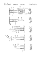
- FIG. 1 is a representation, partly in section, of a gun ammunition cartridge manufactured in accordance with the present invention, and;
- FIGS. 2A-2E constitute a representation of one embodiment of the method of the present invention, FIG. 2E being a sectioned plan view.
- an ammunition cartridge case is mounted upright with its open end directed upwardly.
- a measured quantity of gun powder is admitted to the case.
- a generally cylindrical projectile having a length sufficient to cause a substantial portion thereof to project inwardly into the case beyond the inboard terminal end of the neck of the case when the projectile is fully seated in the case, is inserted into the case a distance which causes the trailing end of the projectile to terminate short of contact with the powder charge within the upright case.
- the case is inverted, causing a portion of the powder charge to flow by gravity downwardly into, and to fill a portion of the annular space between the outer surface of the projectile and the inner surface of the case.
- Remaining powder from the initial powder charge lies loosely above the trailing end of the projectile and in the open space between the projectile and the closed end of the case. Thereafter, and while the case remains inverted, the projectile is further inserted into the case to the extent required to develop the desired overall length of the cartridge. This action pushes the trailing end of the projectile toward the closed end of the case, causing lateral displacement of the powder into the annular space between the projectile and the case as the projectile is moved further into the case. That portion of the powder charge which does not enter the annular space between the projectile and case is pushed gently upwardly to cause the powder to substantially fill the case and thereby be in excellent position for ignition upon firing of the primer of the cartridge.
- the outboard end of the neck of the case is crimped against the circumference of the fully seated projectile to anchor the projectile within the case.
- the quantity of the gun powder admitted to the case is initially calculated to substantially fill the void volume between the projectile and the case when the projectile is fully seated within the case.
- Employing the “two-stage” seating of the projectile to obtain the desired full seating of the projectile within the case precludes the projectile from being forced into such contact with the powder particles as will destroy or alter their individual particulate shapes.
- the gas pressure curve of the gun powder when ignited by the firing of the gun, is a known and unaltered entity, thereby resulting in the desired and intended muzzle velocity of the projectile as it is propelled from the gun.
- the present method results in uniformity of firing from cartridge to cartridge. This uniformity of firing has been found to be obtained by cartridges manufactured in accordance with the present invention, irrespective of whether the intended muzzle velocity of the projectile be subsonic or supersonic.
- a gun ammunition cartridge 12 manufactured in accordance the present method includes a case 14 having a generally cylindrical body portion 16 , a neck 18 , a closed end 20 which houses a primer 21 , and an open end 22 .
- a measured quantity of gun powder 23 is contained within the case and a projectile 24 is disposed within, and closes the open end of the case.
- the projectile is generally cylindrical and provided with an ogive at the leading end 25 thereof.
- the trailing end 26 of the projectile projects inwardly into the interior cavity 28 of the case by a substantial distance inwardly beyond the inboard terminal end 30 of the neck.
- annular space 32 When so positioned within the case, there is defined an annular space 32 between the outer surface 34 of that portion of the projectile which is disposed within the interior volume of the case, and the inner wall surface 36 of the case.
- This annular space is substantially filled with the gun powder 23 , as is the space 37 between the trailing end 26 of the projectile and the closed end 20 of the case.
- the quantity of gun powder initially introduced into the case is selected to occupy all or at least a maximum portion of that interior space (volume) of the case which is not occupied by the projectile.
- the caliber of the cartridge, the weight of the projectile, the desired muzzle velocity of the fired projectile, and the total interior volume of the case must be taken into consideration in determining which type of powder, and what quantity thereof, is to be introduced into the case in order to maintain SAAMI pressures for a given weapon.
- the case 14 of a cartridge is mounted upright on a supporting surface 40 with its open end 22 opening upwardly.
- a measured quantity of a chosen gun powder 23 is introduced into the upright case.
- the trailing end 26 of the projectile 24 is inserted into the case, via the open end 22 and the neck 18 of the case, to a distance wherein the trailing end 26 of the projectile terminates short of the level 42 of the gun powder in the case. This distance is less than the desired full extent of insertion (seating) of the projectile within the case.
- the outer surface 34 of the partially inserted projectile and that portion of the inner wall surface 36 of the case define an open annular space 32 therebetween which is devoid of gun powder as seen in FIG. 2 C.
- the fit between the outer surface 34 of the projectile and the inner surface 44 of the neck provides for frictional engagement therebetween as will preclude the projectile from falling out of the case during subsequent manufacturing operations.
- the case is inverted so that the closed end of the case is directed vertically upward (FIG. 2 D). This action results in the gun powder flowing, by gravity, into and substantially filling the annular space between the projectile and the case.
- this action results in evacuation of gun powder from that volume of the case adjacent the closed end thereof and leaving open space into which the projectile may be moved without materially disturbing the gun powder remaining between the trailing end of the projectile and the closed end of the case.
- the projectile is further inserted into the case to the extent required to obtain full seating of the projectile within the case and establishment of the desired OAL of the cartridge.
- This action in the depicted embodiment, gently radially displaces, but does not physically destroy or alter the shape of, the individual particles of gun powder (FIG. 2 E).
- this action results in the definition of an annular space between the inner wall of the case and the outer surface of that portion of the projectile which projects inwardly of the case and beyond the terminal end of the neck.
- the open end of the cartridge may be crimped against the outer circumference of the projectile to anchor the projectile in the case.
- the completed cartridge is recovered.
- cartridges of 5.56 mm caliber were manufactured with a target muzzle velocity of between about 1300 and about 1400 fps.
- a standard 5.56 mm brass metal cartridge case manufactured by Winchester Division of Olin Corporation of East Alton, Ill. was mounted upright with the open end of the case opening vertically upwardly.
- This case measured 1.760 inches in length and included a primer identified as CCI BR-4 from Blount Incorporated of Lewiston, Id.
- Sixteen grains of N 170 gun powder from Vihtavuori Oy of Finland was measured and poured into the open end of the case. The particles of this powder were of the extruded (grain) type.
- a 5.56 mm projectile which had been fabricated by cold-compacting in a die a mixture of about 97%, by weight, tungsten powder and about 3%, by weight, of tin powder, was selected for seating in the case.
- This projectile was of a length of 1.170 inches, weighed about 150 grains, and had a density of about 95 gm/cc. The trailing end of this projectile was inserted through the open end and neck of the case to a distance just short of the level of the gun powder disposed within the case.
- the case, containing the gun powder and the partly seated projectile was inverted so that the closed end of the case was disposed vertically above the projectile as depicted in FIG. 2 D.
- the process of inverting the incompletely formed cartridge caused the gun powder to flow, by gravity, into, and to fill, the annular space between the projectile and the case wall.
- a portion of the gun powder also covered the trailing end of the projectile.
- the leading end of the projectile was inserted into a die 50 having a die cavity 52 which geometrically matched the ogive on the leading end of the projectile (FIG. 2 E).
- the leading end of the projectile was urged into its fully seated attitude within the case.
- the projectile was inserted into the case to the extent that the OAL of the cartridge was 2.250 inches.
- the same 5.56 mm cartridge was manufactured employing 12.6 grains of gun powder, identified as N-170 from Vihtavuori, Oy of Finland. These cartridges were intended to be fired at subsonic velocities. In test firing of these latter cartridges from an M-16 rifle, the muzzle velocity of each the cartridges was in the subsonic range, with a mean deviation of about 25 fps. Further, these cartridges produced sufficient energy to consistently operate the bolt action of this gun.
- the present inventor has found that ensuring the presence of gun powder in the space between the trailing end of the projectile and the closed end of the case, and in the annular space between the case wall and the projectile, provides for uniform development of gas buildup within the case upon firing of the cartridge.
- This desirable effect enhances the consistency of muzzle velocity of the projectiles fired from cartridge to cartridge of a given caliber. This effect is especially desirable when one is manufacturing cartridges that are intended to propel the projectile from the gun at a subsonic muzzle velocity.
Abstract
Description
Claims (4)
Priority Applications (4)
| Application Number | Priority Date | Filing Date | Title |
|---|---|---|---|
| US09/166,345 US6279447B1 (en) | 1998-10-05 | 1998-10-05 | Method for the manufacture of gun ammunition having elongated projectile and a cartridge produced thereby |
| CA002346674A CA2346674A1 (en) | 1998-10-05 | 1999-09-29 | Method for the manufacture of gun ammunition having elongated projectile and a cartridge produced thereby |
| PCT/US1999/022688 WO2000020819A2 (en) | 1998-10-05 | 1999-09-29 | Method for the manufacture of gun ammunition having elongated projectile and a cartridge produced thereby |
| EP99968024A EP1119737A4 (en) | 1998-10-05 | 1999-09-29 | Method for the manufacture of gun ammunition having elongated projectile and a cartridge produced thereby |
Applications Claiming Priority (1)
| Application Number | Priority Date | Filing Date | Title |
|---|---|---|---|
| US09/166,345 US6279447B1 (en) | 1998-10-05 | 1998-10-05 | Method for the manufacture of gun ammunition having elongated projectile and a cartridge produced thereby |
Publications (1)
| Publication Number | Publication Date |
|---|---|
| US6279447B1 true US6279447B1 (en) | 2001-08-28 |
Family
ID=22602890
Family Applications (1)
| Application Number | Title | Priority Date | Filing Date |
|---|---|---|---|
| US09/166,345 Expired - Lifetime US6279447B1 (en) | 1998-10-05 | 1998-10-05 | Method for the manufacture of gun ammunition having elongated projectile and a cartridge produced thereby |
Country Status (4)
| Country | Link |
|---|---|
| US (1) | US6279447B1 (en) |
| EP (1) | EP1119737A4 (en) |
| CA (1) | CA2346674A1 (en) |
| WO (1) | WO2000020819A2 (en) |
Cited By (5)
| Publication number | Priority date | Publication date | Assignee | Title |
|---|---|---|---|---|
| US20020124759A1 (en) * | 2001-01-09 | 2002-09-12 | Amick Darryl D. | Tungsten-containing articles and methods for forming the same |
| US20040112243A1 (en) * | 2002-01-30 | 2004-06-17 | Amick Darryl D. | Tungsten-containing articles and methods for forming the same |
| US20040216589A1 (en) * | 2002-10-31 | 2004-11-04 | Amick Darryl D. | Tungsten-containing articles and methods for forming the same |
| US10260850B2 (en) | 2016-03-18 | 2019-04-16 | Environ-Metal, Inc. | Frangible firearm projectiles, methods for forming the same, and firearm cartridges containing the same |
| US10690465B2 (en) | 2016-03-18 | 2020-06-23 | Environ-Metal, Inc. | Frangible firearm projectiles, methods for forming the same, and firearm cartridges containing the same |
Citations (7)
| Publication number | Priority date | Publication date | Assignee | Title |
|---|---|---|---|---|
| DE18238C (en) * | J. J. ATKINSON und J. NEEDHAM in London, England | Innovations in cartridges | ||
| US2971426A (en) * | 1959-03-26 | 1961-02-14 | George C Potts | Method of loading fin stabilized ammunition |
| US3137198A (en) * | 1963-03-13 | 1964-06-16 | George C Potts | Apparatus and process for loading propellant in fin type round |
| CH380586A (en) * | 1961-01-20 | 1964-07-31 | Sig Schweiz Industrieges | cartridge |
| CH409705A (en) * | 1963-11-26 | 1966-03-15 | Sfindex | Supersonic velocity projectile |
| US4689185A (en) * | 1986-07-25 | 1987-08-25 | Olin Corporation | Priming method for rimfire cartridge |
| US4846068A (en) * | 1986-07-08 | 1989-07-11 | Steyr-Daimler-Puch Aktiengesellschaft | Cartridge for firearms |
-
1998
- 1998-10-05 US US09/166,345 patent/US6279447B1/en not_active Expired - Lifetime
-
1999
- 1999-09-29 EP EP99968024A patent/EP1119737A4/en not_active Ceased
- 1999-09-29 CA CA002346674A patent/CA2346674A1/en not_active Abandoned
- 1999-09-29 WO PCT/US1999/022688 patent/WO2000020819A2/en not_active Application Discontinuation
Patent Citations (7)
| Publication number | Priority date | Publication date | Assignee | Title |
|---|---|---|---|---|
| DE18238C (en) * | J. J. ATKINSON und J. NEEDHAM in London, England | Innovations in cartridges | ||
| US2971426A (en) * | 1959-03-26 | 1961-02-14 | George C Potts | Method of loading fin stabilized ammunition |
| CH380586A (en) * | 1961-01-20 | 1964-07-31 | Sig Schweiz Industrieges | cartridge |
| US3137198A (en) * | 1963-03-13 | 1964-06-16 | George C Potts | Apparatus and process for loading propellant in fin type round |
| CH409705A (en) * | 1963-11-26 | 1966-03-15 | Sfindex | Supersonic velocity projectile |
| US4846068A (en) * | 1986-07-08 | 1989-07-11 | Steyr-Daimler-Puch Aktiengesellschaft | Cartridge for firearms |
| US4689185A (en) * | 1986-07-25 | 1987-08-25 | Olin Corporation | Priming method for rimfire cartridge |
Cited By (10)
| Publication number | Priority date | Publication date | Assignee | Title |
|---|---|---|---|---|
| US20020124759A1 (en) * | 2001-01-09 | 2002-09-12 | Amick Darryl D. | Tungsten-containing articles and methods for forming the same |
| US7217389B2 (en) | 2001-01-09 | 2007-05-15 | Amick Darryl D | Tungsten-containing articles and methods for forming the same |
| US20040112243A1 (en) * | 2002-01-30 | 2004-06-17 | Amick Darryl D. | Tungsten-containing articles and methods for forming the same |
| US6823798B2 (en) * | 2002-01-30 | 2004-11-30 | Darryl D. Amick | Tungsten-containing articles and methods for forming the same |
| US20040216589A1 (en) * | 2002-10-31 | 2004-11-04 | Amick Darryl D. | Tungsten-containing articles and methods for forming the same |
| US7059233B2 (en) | 2002-10-31 | 2006-06-13 | Amick Darryl D | Tungsten-containing articles and methods for forming the same |
| US10260850B2 (en) | 2016-03-18 | 2019-04-16 | Environ-Metal, Inc. | Frangible firearm projectiles, methods for forming the same, and firearm cartridges containing the same |
| US10690465B2 (en) | 2016-03-18 | 2020-06-23 | Environ-Metal, Inc. | Frangible firearm projectiles, methods for forming the same, and firearm cartridges containing the same |
| US11280597B2 (en) | 2016-03-18 | 2022-03-22 | Federal Cartridge Company | Frangible firearm projectiles, methods for forming the same, and firearm cartridges containing the same |
| US11359896B2 (en) | 2016-03-18 | 2022-06-14 | Federal Cartridge Company | Frangible firearm projectiles, methods for forming the same, and firearm cartridges containing the same |
Also Published As
| Publication number | Publication date |
|---|---|
| WO2000020819A3 (en) | 2000-07-20 |
| EP1119737A2 (en) | 2001-08-01 |
| EP1119737A4 (en) | 2002-11-13 |
| CA2346674A1 (en) | 2000-04-13 |
| WO2000020819A2 (en) | 2000-04-13 |
Similar Documents
| Publication | Publication Date | Title |
|---|---|---|
| US5151555A (en) | Composite cartridge for high velocity rifles and the like | |
| US5822904A (en) | Subsuoic ammunition | |
| US5259288A (en) | Pressure regulating composite cartridge | |
| US5033386A (en) | Composite cartridge for high velocity rifles and the like | |
| US8261667B2 (en) | Lead attached sabot slug | |
| US4142467A (en) | Projectile with sabot | |
| US7814820B2 (en) | Method and apparatus for manufacturing wad-less ammunition | |
| US5375529A (en) | Prefragmenting munitions | |
| US6895865B2 (en) | Sabot for muzzleloading firearm | |
| WO1995013516A1 (en) | Pressure-regulating composite cartridge with gas expansion zone | |
| US10866075B2 (en) | Projectile having leading surface standoffs | |
| US6279447B1 (en) | Method for the manufacture of gun ammunition having elongated projectile and a cartridge produced thereby | |
| CA1337962C (en) | Composite cartridge for high velocity rifles and the like | |
| US4846071A (en) | Base-bleed gas generator for a projectile, shell or the like | |
| WO2008090505A2 (en) | Reloadable subsonic rifle cartridge | |
| EP0966649B1 (en) | Subsonic ammunition for small-bore weapons having a novel projectile | |
| US20060081148A1 (en) | Round of rifle ammuniton and method for making same | |
| US20230384070A1 (en) | Firearm ammunition component and method of use | |
| EP0555107A2 (en) | Shotgun cartridge shell with tracer | |
| JPH0445757B2 (en) | ||
| WO1993015374A1 (en) | Sabot for high dispersion shot shell | |
| RU2095735C1 (en) | Unitary small caliber cartridge | |
| WO2023086759A1 (en) | Caseless tapered-bore ammunition and firearm | |
| WO1998040675A1 (en) | Plated projectile for use in subsonic ammunition | |
| AU3204789A (en) | Composite cartridge for high velocity rifles and the like |
Legal Events
| Date | Code | Title | Description |
|---|---|---|---|
| AS | Assignment |
Owner name: COVE CORPORATION, TENNESSEE Free format text: ASSIGNMENT OF ASSIGNORS INTEREST;ASSIGNOR:BEAL, HAROLD F.;REEL/FRAME:009498/0092 Effective date: 19970820 |
|
| STCF | Information on status: patent grant |
Free format text: PATENTED CASE |
|
| AS | Assignment |
Owner name: DORIS NEBEL BEAL INTER VIVOS PATENT TRUST, A PATEN Free format text: ASSIGNMENT OF ASSIGNORS INTEREST;ASSIGNOR:BEAL, HAROLD F.;REEL/FRAME:012376/0235 Effective date: 20011022 |
|
| FEPP | Fee payment procedure |
Free format text: PAT HOLDER NO LONGER CLAIMS SMALL ENTITY STATUS, ENTITY STATUS SET TO UNDISCOUNTED (ORIGINAL EVENT CODE: STOL); ENTITY STATUS OF PATENT OWNER: SMALL ENTITY |
|
| REFU | Refund |
Free format text: REFUND - SURCHARGE FOR LATE PAYMENT, SMALL ENTITY (ORIGINAL EVENT CODE: R2554); ENTITY STATUS OF PATENT OWNER: SMALL ENTITY Free format text: REFUND - SURCHARGE, PETITION TO ACCEPT PYMT AFTER EXP, UNINTENTIONAL (ORIGINAL EVENT CODE: R2551); ENTITY STATUS OF PATENT OWNER: SMALL ENTITY |
|
| REMI | Maintenance fee reminder mailed | ||
| FPAY | Fee payment |
Year of fee payment: 4 |
|
| SULP | Surcharge for late payment | ||
| FEPP | Fee payment procedure |
Free format text: PAT HOLDER CLAIMS SMALL ENTITY STATUS, ENTITY STATUS SET TO SMALL (ORIGINAL EVENT CODE: LTOS); ENTITY STATUS OF PATENT OWNER: SMALL ENTITY |
|
| FPAY | Fee payment |
Year of fee payment: 8 |
|
| AS | Assignment |
Owner name: AWC SYSTEMS TECHNOLOGY, LLC, ARIZONA Free format text: ASSIGNMENT OF ASSIGNORS INTEREST;ASSIGNORS:DORIS NEBEL BEAL INTER VIVOS PATENT TRUST;BEAL, HAROLD F.;REEL/FRAME:028846/0274 Effective date: 20120801 |
|
| AS | Assignment |
Owner name: DORIS NEBEL BEAL INTER VIVOS PATENT TRUST, TENNESS Free format text: SECURITY AGREEMENT;ASSIGNOR:AWC SYSTEMS TECHNOLOGY, LLC;REEL/FRAME:028866/0703 Effective date: 20120801 |
|
| FPAY | Fee payment |
Year of fee payment: 12 |
|
| AS | Assignment |
Owner name: DORIS NEBEL BEAL INTER VIVOS PATENT TRUST, TENNESS Free format text: ASSIGNMENT OF ASSIGNORS INTEREST;ASSIGNORS:STRATEGIC ARMORY CORPS, LLC;AWC SYSTEMS TECHNOLOGY, LLC;REEL/FRAME:044500/0782 Effective date: 20170922 |
|
| AS | Assignment |
Owner name: BEAL, SHAINE A., SOUTH CAROLINA Free format text: ASSIGNMENT OF ASSIGNORS INTEREST;ASSIGNOR:DORIS NEBEL BEAL INTER VIVOS PATENT TRUST;REEL/FRAME:045444/0070 Effective date: 20180119 Owner name: NEELY, MARION B., SOUTH CAROLINA Free format text: ASSIGNMENT OF ASSIGNORS INTEREST;ASSIGNOR:DORIS NEBEL BEAL INTER VIVOS PATENT TRUST;REEL/FRAME:045444/0070 Effective date: 20180119 Owner name: MEALS, LLC, TENNESSEE Free format text: ASSIGNMENT OF ASSIGNORS INTEREST;ASSIGNOR:NEELY, MARION B.;REEL/FRAME:045445/0058 Effective date: 20180119 |
|
| AS | Assignment |
Owner name: MEALS, LLC, TENNESSEE Free format text: ASSIGNMENT OF ASSIGNORS INTEREST;ASSIGNOR:BEAL, SHAINE A.;REEL/FRAME:045459/0376 Effective date: 20180119 |