US6296726B1 - Method and apparatus for spin welding container closures - Google Patents
Method and apparatus for spin welding container closures Download PDFInfo
- Publication number
- US6296726B1 US6296726B1 US09/593,064 US59306400A US6296726B1 US 6296726 B1 US6296726 B1 US 6296726B1 US 59306400 A US59306400 A US 59306400A US 6296726 B1 US6296726 B1 US 6296726B1
- Authority
- US
- United States
- Prior art keywords
- lid
- accordance
- rotation
- bowl
- synthetic resin
- Prior art date
- Legal status (The legal status is an assumption and is not a legal conclusion. Google has not performed a legal analysis and makes no representation as to the accuracy of the status listed.)
- Expired - Lifetime
Links
Images


Classifications
-
- B—PERFORMING OPERATIONS; TRANSPORTING
- B29—WORKING OF PLASTICS; WORKING OF SUBSTANCES IN A PLASTIC STATE IN GENERAL
- B29C—SHAPING OR JOINING OF PLASTICS; SHAPING OF MATERIAL IN A PLASTIC STATE, NOT OTHERWISE PROVIDED FOR; AFTER-TREATMENT OF THE SHAPED PRODUCTS, e.g. REPAIRING
- B29C65/00—Joining or sealing of preformed parts, e.g. welding of plastics materials; Apparatus therefor
- B29C65/78—Means for handling the parts to be joined, e.g. for making containers or hollow articles, e.g. means for handling sheets, plates, web-like materials, tubular articles, hollow articles or elements to be joined therewith; Means for discharging the joined articles from the joining apparatus
- B29C65/7858—Means for handling the parts to be joined, e.g. for making containers or hollow articles, e.g. means for handling sheets, plates, web-like materials, tubular articles, hollow articles or elements to be joined therewith; Means for discharging the joined articles from the joining apparatus characterised by the feeding movement of the parts to be joined
- B29C65/7861—In-line machines, i.e. feeding, joining and discharging are in one production line
- B29C65/787—In-line machines, i.e. feeding, joining and discharging are in one production line using conveyor belts or conveyor chains
- B29C65/7873—In-line machines, i.e. feeding, joining and discharging are in one production line using conveyor belts or conveyor chains using cooperating conveyor belts or cooperating conveyor chains
-
- B—PERFORMING OPERATIONS; TRANSPORTING
- B29—WORKING OF PLASTICS; WORKING OF SUBSTANCES IN A PLASTIC STATE IN GENERAL
- B29C—SHAPING OR JOINING OF PLASTICS; SHAPING OF MATERIAL IN A PLASTIC STATE, NOT OTHERWISE PROVIDED FOR; AFTER-TREATMENT OF THE SHAPED PRODUCTS, e.g. REPAIRING
- B29C65/00—Joining or sealing of preformed parts, e.g. welding of plastics materials; Apparatus therefor
- B29C65/02—Joining or sealing of preformed parts, e.g. welding of plastics materials; Apparatus therefor by heating, with or without pressure
- B29C65/06—Joining or sealing of preformed parts, e.g. welding of plastics materials; Apparatus therefor by heating, with or without pressure using friction, e.g. spin welding
- B29C65/0672—Spin welding
-
- B—PERFORMING OPERATIONS; TRANSPORTING
- B29—WORKING OF PLASTICS; WORKING OF SUBSTANCES IN A PLASTIC STATE IN GENERAL
- B29C—SHAPING OR JOINING OF PLASTICS; SHAPING OF MATERIAL IN A PLASTIC STATE, NOT OTHERWISE PROVIDED FOR; AFTER-TREATMENT OF THE SHAPED PRODUCTS, e.g. REPAIRING
- B29C65/00—Joining or sealing of preformed parts, e.g. welding of plastics materials; Apparatus therefor
- B29C65/78—Means for handling the parts to be joined, e.g. for making containers or hollow articles, e.g. means for handling sheets, plates, web-like materials, tubular articles, hollow articles or elements to be joined therewith; Means for discharging the joined articles from the joining apparatus
- B29C65/7841—Holding or clamping means for handling purposes
-
- B—PERFORMING OPERATIONS; TRANSPORTING
- B29—WORKING OF PLASTICS; WORKING OF SUBSTANCES IN A PLASTIC STATE IN GENERAL
- B29C—SHAPING OR JOINING OF PLASTICS; SHAPING OF MATERIAL IN A PLASTIC STATE, NOT OTHERWISE PROVIDED FOR; AFTER-TREATMENT OF THE SHAPED PRODUCTS, e.g. REPAIRING
- B29C66/00—General aspects of processes or apparatus for joining preformed parts
- B29C66/01—General aspects dealing with the joint area or with the area to be joined
- B29C66/05—Particular design of joint configurations
- B29C66/10—Particular design of joint configurations particular design of the joint cross-sections
- B29C66/12—Joint cross-sections combining only two joint-segments; Tongue and groove joints; Tenon and mortise joints; Stepped joint cross-sections
- B29C66/124—Tongue and groove joints
- B29C66/1246—Tongue and groove joints characterised by the female part, i.e. the part comprising the groove
- B29C66/12463—Tongue and groove joints characterised by the female part, i.e. the part comprising the groove being tapered
-
- B—PERFORMING OPERATIONS; TRANSPORTING
- B29—WORKING OF PLASTICS; WORKING OF SUBSTANCES IN A PLASTIC STATE IN GENERAL
- B29C—SHAPING OR JOINING OF PLASTICS; SHAPING OF MATERIAL IN A PLASTIC STATE, NOT OTHERWISE PROVIDED FOR; AFTER-TREATMENT OF THE SHAPED PRODUCTS, e.g. REPAIRING
- B29C66/00—General aspects of processes or apparatus for joining preformed parts
- B29C66/01—General aspects dealing with the joint area or with the area to be joined
- B29C66/05—Particular design of joint configurations
- B29C66/10—Particular design of joint configurations particular design of the joint cross-sections
- B29C66/12—Joint cross-sections combining only two joint-segments; Tongue and groove joints; Tenon and mortise joints; Stepped joint cross-sections
- B29C66/124—Tongue and groove joints
- B29C66/1246—Tongue and groove joints characterised by the female part, i.e. the part comprising the groove
- B29C66/12469—Tongue and groove joints characterised by the female part, i.e. the part comprising the groove being asymmetric
-
- B—PERFORMING OPERATIONS; TRANSPORTING
- B29—WORKING OF PLASTICS; WORKING OF SUBSTANCES IN A PLASTIC STATE IN GENERAL
- B29C—SHAPING OR JOINING OF PLASTICS; SHAPING OF MATERIAL IN A PLASTIC STATE, NOT OTHERWISE PROVIDED FOR; AFTER-TREATMENT OF THE SHAPED PRODUCTS, e.g. REPAIRING
- B29C66/00—General aspects of processes or apparatus for joining preformed parts
- B29C66/01—General aspects dealing with the joint area or with the area to be joined
- B29C66/05—Particular design of joint configurations
- B29C66/10—Particular design of joint configurations particular design of the joint cross-sections
- B29C66/12—Joint cross-sections combining only two joint-segments; Tongue and groove joints; Tenon and mortise joints; Stepped joint cross-sections
- B29C66/124—Tongue and groove joints
- B29C66/1248—Interpenetrating groove joints
-
- B—PERFORMING OPERATIONS; TRANSPORTING
- B29—WORKING OF PLASTICS; WORKING OF SUBSTANCES IN A PLASTIC STATE IN GENERAL
- B29C—SHAPING OR JOINING OF PLASTICS; SHAPING OF MATERIAL IN A PLASTIC STATE, NOT OTHERWISE PROVIDED FOR; AFTER-TREATMENT OF THE SHAPED PRODUCTS, e.g. REPAIRING
- B29C66/00—General aspects of processes or apparatus for joining preformed parts
- B29C66/01—General aspects dealing with the joint area or with the area to be joined
- B29C66/05—Particular design of joint configurations
- B29C66/10—Particular design of joint configurations particular design of the joint cross-sections
- B29C66/13—Single flanged joints; Fin-type joints; Single hem joints; Edge joints; Interpenetrating fingered joints; Other specific particular designs of joint cross-sections not provided for in groups B29C66/11 - B29C66/12
- B29C66/131—Single flanged joints, i.e. one of the parts to be joined being rigid and flanged in the joint area
-
- B—PERFORMING OPERATIONS; TRANSPORTING
- B29—WORKING OF PLASTICS; WORKING OF SUBSTANCES IN A PLASTIC STATE IN GENERAL
- B29C—SHAPING OR JOINING OF PLASTICS; SHAPING OF MATERIAL IN A PLASTIC STATE, NOT OTHERWISE PROVIDED FOR; AFTER-TREATMENT OF THE SHAPED PRODUCTS, e.g. REPAIRING
- B29C66/00—General aspects of processes or apparatus for joining preformed parts
- B29C66/50—General aspects of joining tubular articles; General aspects of joining long products, i.e. bars or profiled elements; General aspects of joining single elements to tubular articles, hollow articles or bars; General aspects of joining several hollow-preforms to form hollow or tubular articles
- B29C66/51—Joining tubular articles, profiled elements or bars; Joining single elements to tubular articles, hollow articles or bars; Joining several hollow-preforms to form hollow or tubular articles
- B29C66/54—Joining several hollow-preforms, e.g. half-shells, to form hollow articles, e.g. for making balls, containers; Joining several hollow-preforms, e.g. half-cylinders, to form tubular articles
- B29C66/542—Joining several hollow-preforms, e.g. half-shells, to form hollow articles, e.g. for making balls, containers; Joining several hollow-preforms, e.g. half-cylinders, to form tubular articles joining hollow covers or hollow bottoms to open ends of container bodies
-
- B—PERFORMING OPERATIONS; TRANSPORTING
- B29—WORKING OF PLASTICS; WORKING OF SUBSTANCES IN A PLASTIC STATE IN GENERAL
- B29C—SHAPING OR JOINING OF PLASTICS; SHAPING OF MATERIAL IN A PLASTIC STATE, NOT OTHERWISE PROVIDED FOR; AFTER-TREATMENT OF THE SHAPED PRODUCTS, e.g. REPAIRING
- B29C66/00—General aspects of processes or apparatus for joining preformed parts
- B29C66/80—General aspects of machine operations or constructions and parts thereof
- B29C66/82—Pressure application arrangements, e.g. transmission or actuating mechanisms for joining tools or clamps
- B29C66/824—Actuating mechanisms
- B29C66/8242—Pneumatic or hydraulic drives
-
- B—PERFORMING OPERATIONS; TRANSPORTING
- B29—WORKING OF PLASTICS; WORKING OF SUBSTANCES IN A PLASTIC STATE IN GENERAL
- B29C—SHAPING OR JOINING OF PLASTICS; SHAPING OF MATERIAL IN A PLASTIC STATE, NOT OTHERWISE PROVIDED FOR; AFTER-TREATMENT OF THE SHAPED PRODUCTS, e.g. REPAIRING
- B29C66/00—General aspects of processes or apparatus for joining preformed parts
- B29C66/80—General aspects of machine operations or constructions and parts thereof
- B29C66/82—Pressure application arrangements, e.g. transmission or actuating mechanisms for joining tools or clamps
- B29C66/824—Actuating mechanisms
- B29C66/8246—Servomechanisms, e.g. servomotors
-
- B—PERFORMING OPERATIONS; TRANSPORTING
- B29—WORKING OF PLASTICS; WORKING OF SUBSTANCES IN A PLASTIC STATE IN GENERAL
- B29C—SHAPING OR JOINING OF PLASTICS; SHAPING OF MATERIAL IN A PLASTIC STATE, NOT OTHERWISE PROVIDED FOR; AFTER-TREATMENT OF THE SHAPED PRODUCTS, e.g. REPAIRING
- B29C66/00—General aspects of processes or apparatus for joining preformed parts
- B29C66/80—General aspects of machine operations or constructions and parts thereof
- B29C66/83—General aspects of machine operations or constructions and parts thereof characterised by the movement of the joining or pressing tools
- B29C66/832—Reciprocating joining or pressing tools
- B29C66/8322—Joining or pressing tools reciprocating along one axis
-
- B—PERFORMING OPERATIONS; TRANSPORTING
- B29—WORKING OF PLASTICS; WORKING OF SUBSTANCES IN A PLASTIC STATE IN GENERAL
- B29C—SHAPING OR JOINING OF PLASTICS; SHAPING OF MATERIAL IN A PLASTIC STATE, NOT OTHERWISE PROVIDED FOR; AFTER-TREATMENT OF THE SHAPED PRODUCTS, e.g. REPAIRING
- B29C66/00—General aspects of processes or apparatus for joining preformed parts
- B29C66/80—General aspects of machine operations or constructions and parts thereof
- B29C66/84—Specific machine types or machines suitable for specific applications
- B29C66/849—Packaging machines
-
- B—PERFORMING OPERATIONS; TRANSPORTING
- B29—WORKING OF PLASTICS; WORKING OF SUBSTANCES IN A PLASTIC STATE IN GENERAL
- B29C—SHAPING OR JOINING OF PLASTICS; SHAPING OF MATERIAL IN A PLASTIC STATE, NOT OTHERWISE PROVIDED FOR; AFTER-TREATMENT OF THE SHAPED PRODUCTS, e.g. REPAIRING
- B29C66/00—General aspects of processes or apparatus for joining preformed parts
- B29C66/90—Measuring or controlling the joining process
- B29C66/92—Measuring or controlling the joining process by measuring or controlling the pressure, the force, the mechanical power or the displacement of the joining tools
- B29C66/924—Measuring or controlling the joining process by measuring or controlling the pressure, the force, the mechanical power or the displacement of the joining tools by controlling or regulating the pressure, the force, the mechanical power or the displacement of the joining tools
- B29C66/9241—Measuring or controlling the joining process by measuring or controlling the pressure, the force, the mechanical power or the displacement of the joining tools by controlling or regulating the pressure, the force, the mechanical power or the displacement of the joining tools by controlling or regulating the pressure, the force or the mechanical power
- B29C66/92431—Measuring or controlling the joining process by measuring or controlling the pressure, the force, the mechanical power or the displacement of the joining tools by controlling or regulating the pressure, the force, the mechanical power or the displacement of the joining tools by controlling or regulating the pressure, the force or the mechanical power the pressure, the force or the mechanical power being kept constant over time
-
- B—PERFORMING OPERATIONS; TRANSPORTING
- B29—WORKING OF PLASTICS; WORKING OF SUBSTANCES IN A PLASTIC STATE IN GENERAL
- B29C—SHAPING OR JOINING OF PLASTICS; SHAPING OF MATERIAL IN A PLASTIC STATE, NOT OTHERWISE PROVIDED FOR; AFTER-TREATMENT OF THE SHAPED PRODUCTS, e.g. REPAIRING
- B29C66/00—General aspects of processes or apparatus for joining preformed parts
- B29C66/90—Measuring or controlling the joining process
- B29C66/92—Measuring or controlling the joining process by measuring or controlling the pressure, the force, the mechanical power or the displacement of the joining tools
- B29C66/929—Measuring or controlling the joining process by measuring or controlling the pressure, the force, the mechanical power or the displacement of the joining tools characterized by specific pressure, force, mechanical power or displacement values or ranges
- B29C66/9292—Measuring or controlling the joining process by measuring or controlling the pressure, the force, the mechanical power or the displacement of the joining tools characterized by specific pressure, force, mechanical power or displacement values or ranges in explicit relation to another variable, e.g. pressure diagrams
- B29C66/92921—Measuring or controlling the joining process by measuring or controlling the pressure, the force, the mechanical power or the displacement of the joining tools characterized by specific pressure, force, mechanical power or displacement values or ranges in explicit relation to another variable, e.g. pressure diagrams in specific relation to time, e.g. pressure-time diagrams
-
- B—PERFORMING OPERATIONS; TRANSPORTING
- B29—WORKING OF PLASTICS; WORKING OF SUBSTANCES IN A PLASTIC STATE IN GENERAL
- B29C—SHAPING OR JOINING OF PLASTICS; SHAPING OF MATERIAL IN A PLASTIC STATE, NOT OTHERWISE PROVIDED FOR; AFTER-TREATMENT OF THE SHAPED PRODUCTS, e.g. REPAIRING
- B29C66/00—General aspects of processes or apparatus for joining preformed parts
- B29C66/90—Measuring or controlling the joining process
- B29C66/93—Measuring or controlling the joining process by measuring or controlling the speed
- B29C66/934—Measuring or controlling the joining process by measuring or controlling the speed by controlling or regulating the speed
- B29C66/93441—Measuring or controlling the joining process by measuring or controlling the speed by controlling or regulating the speed the speed being non-constant over time
-
- B—PERFORMING OPERATIONS; TRANSPORTING
- B29—WORKING OF PLASTICS; WORKING OF SUBSTANCES IN A PLASTIC STATE IN GENERAL
- B29C—SHAPING OR JOINING OF PLASTICS; SHAPING OF MATERIAL IN A PLASTIC STATE, NOT OTHERWISE PROVIDED FOR; AFTER-TREATMENT OF THE SHAPED PRODUCTS, e.g. REPAIRING
- B29C66/00—General aspects of processes or apparatus for joining preformed parts
- B29C66/90—Measuring or controlling the joining process
- B29C66/93—Measuring or controlling the joining process by measuring or controlling the speed
- B29C66/934—Measuring or controlling the joining process by measuring or controlling the speed by controlling or regulating the speed
- B29C66/93451—Measuring or controlling the joining process by measuring or controlling the speed by controlling or regulating the speed by controlling or regulating the rotational speed, i.e. the speed of revolution
-
- B—PERFORMING OPERATIONS; TRANSPORTING
- B29—WORKING OF PLASTICS; WORKING OF SUBSTANCES IN A PLASTIC STATE IN GENERAL
- B29C—SHAPING OR JOINING OF PLASTICS; SHAPING OF MATERIAL IN A PLASTIC STATE, NOT OTHERWISE PROVIDED FOR; AFTER-TREATMENT OF THE SHAPED PRODUCTS, e.g. REPAIRING
- B29C66/00—General aspects of processes or apparatus for joining preformed parts
- B29C66/90—Measuring or controlling the joining process
- B29C66/93—Measuring or controlling the joining process by measuring or controlling the speed
- B29C66/939—Measuring or controlling the joining process by measuring or controlling the speed characterised by specific speed values or ranges
- B29C66/9392—Measuring or controlling the joining process by measuring or controlling the speed characterised by specific speed values or ranges in explicit relation to another variable, e.g. speed diagrams
-
- B—PERFORMING OPERATIONS; TRANSPORTING
- B29—WORKING OF PLASTICS; WORKING OF SUBSTANCES IN A PLASTIC STATE IN GENERAL
- B29C—SHAPING OR JOINING OF PLASTICS; SHAPING OF MATERIAL IN A PLASTIC STATE, NOT OTHERWISE PROVIDED FOR; AFTER-TREATMENT OF THE SHAPED PRODUCTS, e.g. REPAIRING
- B29C66/00—General aspects of processes or apparatus for joining preformed parts
- B29C66/90—Measuring or controlling the joining process
- B29C66/96—Measuring or controlling the joining process characterised by the method for implementing the controlling of the joining process
- B29C66/961—Measuring or controlling the joining process characterised by the method for implementing the controlling of the joining process involving a feedback loop mechanism, e.g. comparison with a desired value
-
- B—PERFORMING OPERATIONS; TRANSPORTING
- B65—CONVEYING; PACKING; STORING; HANDLING THIN OR FILAMENTARY MATERIAL
- B65B—MACHINES, APPARATUS OR DEVICES FOR, OR METHODS OF, PACKAGING ARTICLES OR MATERIALS; UNPACKING
- B65B7/00—Closing containers or receptacles after filling
- B65B7/16—Closing semi-rigid or rigid containers or receptacles not deformed by, or not taking-up shape of, contents, e.g. boxes or cartons
- B65B7/28—Closing semi-rigid or rigid containers or receptacles not deformed by, or not taking-up shape of, contents, e.g. boxes or cartons by applying separate preformed closures, e.g. lids, covers
- B65B7/2842—Securing closures on containers
- B65B7/2878—Securing closures on containers by heat-sealing
-
- B—PERFORMING OPERATIONS; TRANSPORTING
- B29—WORKING OF PLASTICS; WORKING OF SUBSTANCES IN A PLASTIC STATE IN GENERAL
- B29C—SHAPING OR JOINING OF PLASTICS; SHAPING OF MATERIAL IN A PLASTIC STATE, NOT OTHERWISE PROVIDED FOR; AFTER-TREATMENT OF THE SHAPED PRODUCTS, e.g. REPAIRING
- B29C66/00—General aspects of processes or apparatus for joining preformed parts
- B29C66/90—Measuring or controlling the joining process
- B29C66/92—Measuring or controlling the joining process by measuring or controlling the pressure, the force, the mechanical power or the displacement of the joining tools
- B29C66/922—Measuring or controlling the joining process by measuring or controlling the pressure, the force, the mechanical power or the displacement of the joining tools by measuring the pressure, the force, the mechanical power or the displacement of the joining tools
- B29C66/9221—Measuring or controlling the joining process by measuring or controlling the pressure, the force, the mechanical power or the displacement of the joining tools by measuring the pressure, the force, the mechanical power or the displacement of the joining tools by measuring the pressure, the force or the mechanical power
-
- B—PERFORMING OPERATIONS; TRANSPORTING
- B29—WORKING OF PLASTICS; WORKING OF SUBSTANCES IN A PLASTIC STATE IN GENERAL
- B29C—SHAPING OR JOINING OF PLASTICS; SHAPING OF MATERIAL IN A PLASTIC STATE, NOT OTHERWISE PROVIDED FOR; AFTER-TREATMENT OF THE SHAPED PRODUCTS, e.g. REPAIRING
- B29C66/00—General aspects of processes or apparatus for joining preformed parts
- B29C66/90—Measuring or controlling the joining process
- B29C66/93—Measuring or controlling the joining process by measuring or controlling the speed
- B29C66/932—Measuring or controlling the joining process by measuring or controlling the speed by measuring the speed
-
- B—PERFORMING OPERATIONS; TRANSPORTING
- B29—WORKING OF PLASTICS; WORKING OF SUBSTANCES IN A PLASTIC STATE IN GENERAL
- B29C—SHAPING OR JOINING OF PLASTICS; SHAPING OF MATERIAL IN A PLASTIC STATE, NOT OTHERWISE PROVIDED FOR; AFTER-TREATMENT OF THE SHAPED PRODUCTS, e.g. REPAIRING
- B29C66/00—General aspects of processes or apparatus for joining preformed parts
- B29C66/90—Measuring or controlling the joining process
- B29C66/93—Measuring or controlling the joining process by measuring or controlling the speed
- B29C66/939—Measuring or controlling the joining process by measuring or controlling the speed characterised by specific speed values or ranges
Definitions
- the present invention relates to the sealing of plastic lids or closures to plastic containers and, more particularly, to the spin welding of lids and containers.
- the process of spin welding is one in which the friction between relatively rotating lids and containers such as bowls and cups causes the synthetic resin at abutting surfaces to melt and bond the two surfaces upon cooling.
- many spin welding processes have involved spinning the lid or cover at a relatively high speed and then bringing it into contact with the container which produces the melting friction as the lid rotation is slowed and then stops.
- Exemplary of such a process is U.S. Pat. No. 3,297,504 to Brown et al.
- Another object is to provide novel apparatus for spin welding lids and containers which accommodates surface variations and produces well sealed containers.
- a method of making sealed synthetic resin containers which comprises molding thermoplastic synthetic resin into bowls and lids which have substantially complimentary mating surfaces extending about the periphery thereof.
- One of the bowls is filled with product, and the opposed, generally horizontal mating surfaces of the lid and bowl are brought into contact under a predetermined axial pressure while gripping the bowl and lid securely.
- the lid is rotated to the bowl with rapidly accelerating rotation while maintaining substantially the axial pressure to produce melting of the mating surfaces until a desired torque value is attained.
- the rotation of the lid is then immediately decelerated to terminate the rotation and allow the mating surfaces to bond.
- the rotation is effected at a high degree of acceleration and the termination of rotation is effected at a high degree of deceleration.
- the torque is monitored repeatedly during the step of accelerating rotation until a plateau is reached, and the rotation is continued for at least 50 milliseconds thereafter.
- the monitoring of the torque is conveniently effected by monitoring the power being drawn by a motor used for producing the accelerating rotation.
- the predetermined axial pressure is preferably 200-500 p.s.i., and the acceleration and termination of rotation is effected in less than four relative rotations of the lid relative to the bowl. Both the acceleration and deceleration are at a rate of 35,000-250,000 rpm/sec.
- the step of directing steam onto the mating surface of the bowl prior to bringing the lid into contact therewith and nitrogen is preferably admixed with the steam.
- nitrogen is preferably admixed with the steam.
- the apparatus for producing the spin welded containers comprises a holder for firmly gripping a bowl, a holder for firmly gripping a complimentary lid, and means for moving the holders relative to each other to bring mating surfaces into contact.
- Pressure applying means is provided to apply predetermined axial pressure on the abutting surfaces
- acceleration and deceleration means is provided for rapidly accelerating rotation of the holders relative to each other and for rapidly decelerating the relative rotation while maintaining substantially the predetermined axial pressure.
- Torque sensing means is included to sense the torque generated at the mating surfaces which is operative upon the acceleration and deceleration means to determine when the acceleration has reached a desired value indicative of the desired melting of the mating surfaces and then to effect the deceleration.
- FIG. 1 is a front elevational view of the lid spinning assembly of a spin welder embodying the present invention
- FIG. 2 is a side elevational view thereof and also fragmentarily illustrates the bowl holding subassembly
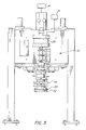
- FIG. 3 is a rear elevational view of the lid spinning assembly of FIG. 1;
- FIG. 4 is a sectional view of the chuck subassembly drawn to an enlarged scale
- FIGS. 5A-5D are graphic representations respectively, of applied pressure, torque, velocity and rotational distance for a cup/lid assembly of different samples to a reach predetermined torque set point;
- FIGS. 6A-6D are graphic representations illustrating the relationships, respectively, of applied pressure, torque, velocity and rotational distance
- FIG. 7 is a flow chart of the logic for the spin weld cycle
- FIG. 8 is an enlarged fragmentary cross sectional view of a bowl holder, bowl and lid prior to the spin welding thereof;
- FIG. 9 a is a bottom view of the lid holder
- FIG. 9 b is a cross sectional view of the lid holder
- FIG. 10 is a fragmentary cross sectional view of the lid holder blade in the section designated by the broken line circle of FIG. 9 and drawn to an enlarged scale;
- FIG. 11 is an enlarged fragmentary illustration of the blade holder and lid engaged thereby
- FIG. 12 is an enlarged fragmentary cross sectional view of the lid and bowl following spin welding
- FIG. 13 is a partially diagrammatic perspective illustration of a production unit for spin welding containers
- FIG. 14 is a diagrammatic plan view of the production unit of FIG. 13.
- FIG. 15 is a graphic representation of velocity and torque during the spin welding operation.
- FIGS. 1-3 therein illustrated is a single station spin welding machine embodying the present invention and which employs a lid supporting and spinning assembly generally designated by the numeral 10 that mounts the lid holder assembly generally designated by the numeral 12 .
- the chuck subassembly 14 of the lid holder assembly 12 includes at its lower end the lid holder 20 in which is seated a lid 32 . Rotation of the chuck subassembly 14 and lid holder 20 are effected by the servomotor 16 through the gear box 30 , and the servomotor 16 and lid holder assembly 12 are vertically movable by the air cylinder/piston 28 on slides 34 .
- a fragmentarily illustrated bowl or cup carrier generally designated by the numeral 24 has a cup holder 26 thereon in which is seated the cup 22 in alignment with the lid 32 .
- the cup holder 26 has a multiplicity of projections or teeth (seen in FIG. 8) about its periphery to grip the cup 22 firmly therein against relative rotation.
- Torque monitoring and power supply means to the servomotor 16 are indicated by the numeral 6 and control and power means for the air cylinder 28 are indicated by the numeral 8 .
- the chuck subassembly 14 is seen to include a linear bearing 44 in which the shaft 38 of the servomotor 16 is slidably seated.
- the shaft 38 acts upon a compression spring 40 so that, when the servomotor 16 moves the lid holder assembly 12 downwardly against the cup carrier 24 , the spring 40 is compressed while the chuck 14 slides upwardly relative thereto.
- the lid holder 20 has a multiplicity of teeth or gripper blades 46 spaced thereabout which are driven into the lid 32 by the downward movement to prevent its rotation therein.
- the cup holder 26 has teeth or gripper blades 48 spaced thereabout which are driven into the cup 22 by the pressure exerted on the upper surface thereof as the lid holder assembly 12 moves downwardly.
- the lid 32 and cup 22 are both restrained against rotation relative to their respective holders 20 , 26 .
- the peripheral portions of the lid 32 and cup 22 are configured to provide a cooperating circular groove or recess 70 and a projecting circular rib 72 which extends thereinto.
- the cup 22 also has a circumferential flange 74 which extends outwardly of the rib 72 and cooperates with a depending circumferential flange 76 on the lid 32 .
- the assembled container is illustrated in FIG. 12 and it can be seen that the resin in the adjacent surfaces of the lid 32 and cup 22 about the recess 70 and rib 72 , and about the flange 74 and flange 76 has fused to provide a relatively large area of bonding and sealing. Any contamination on those adjacent surfaces is expressed circumferentially and any flash is blended between the opposing flanges 74 , 76 .
- a cup 22 is loaded into the cup holder 26 , and the lid 32 is loaded into the lid holder 20 .
- the piston/cylinder 28 is actuated by the control 8 and moves the lid spinning assembly 10 downwardly against the cup 22 in the carrier 24 . As this downward movement takes place, the gripper blades 46 , 48 are embedded into the lid 32 and cup 22 , and the spring 40 is compressed to provide the desired biasing force.
- the servomotor 16 is actuated by the control 6 to effect relative rotation of the lid 32 relative to the cup 22 until the desired torque is reached at which time the control 6 rapidly decelerates the servomotor 16 and relative rotation to produce the desired welding of the opposing surfaces of the lid 32 and cup 22 .
- FIGS. 13 and 14 diagrammatically illustrate a high speed packaging installation provided by a cooperating pair of belt drive units generally designated by the numerals 80 , 82 .
- the unit 82 has a single drive belt 84 which has cup holder elements 86 thereon providing a semi-circular recess 88 .
- the unit 82 has a first drive belt 90 with cooperatively configured cup holder elements 86 thereon, and the belts 84 , 90 are synchronously driven by a gear (not shown).
- the drive paths of the belts 84 , 90 are elongated with arcuate ends.
- the belts 84 , 90 initially converge from the intake end to bring the cup holder elements 86 into abutting relationship, travel parallel through the central spin welding area, and then diverge at the unloading end.
- a conveyor belt 94 extends between the units 80 , 82 below the cup holder elements 86 and conveys the cups 22 into the space between the cup holder elements 86 on the belts 84 , 90 .
- the holder elements 86 firmly grip the cups 22 between them, and the conveyor belt 94 then desirably descends slightly so that the cups 22 are supported only in the holder elements 86 as they pass through the welding station. Thereafter, the conveyor belt 94 ascends to support the welded containers which are released by the holder elements as the belts 84 , 90 diverge towards the discharge end of the installation.
- the unit 82 has a turret 96 with a second drive belt assembly 98 which is synchronously driven with the belts 84 , 90 , and it carries the brackets 100 upon which are mounted the servomotors 102 and which are slidable on the vertical posts 104 by action of cams (not shown) at the entrance and exit ends of the welding area.
- the lids (not shown) are inserted into the lid holders (not shown) on the side of the belt path opposite the welding area.
- the motor 102 , clutch and lid holder containing the lid are moved downwardly by a cam (not shown) at the beginning of the welding area to load the spring and embed the gripper blades in the cup and lid, and a short burst of rotation of the motor 102 produces the spin weld of the opposing surfaces.
- the cups or bowls are filled with the product prior to movement on the conveyor belt into the spin welding installation.
- the method of the present invention is one which involves the rapid acceleration of relative rotation of the lid and disc after they have been brought into contact and are under axial pressure which is maintained during the spin welding operation.
- the torque generated (indicated by the power being drawn) by the motor producing the rotation is monitored to determine when it reaches a plateau and the rotation continues for a short time thereafter, following which the motor and rotation are rapidly decelerated.
- this torque will increase until the opposing surfaces melt and reduce the frictional drag. This ensures that the spin weld cycle lasts only for the time required to obtain sufficient melting to produce a good bond.
- This axial pressure should be at least 100 p.s.i. and is preferably in the range of 200-500 p.s.i.
- the motor and its controller must effect rapid acceleration and deceleration at a rate of 35,000-250,000 rpm/sec. This can be effected by the motor directly or through appropriate gear drive.
- FIGS. 5A-5D illustrate the variation in revolutions for three different specimens to reach the desired plateau in torque while applying the same pressure and rate of acceleration and deceleration.
- FIGS. 6A-6D illustrate the relationship between applied pressure, torque, velocity, acceleration, deceleration and rotational distance for a specimen cup and lid having a diameter of 3 ⁇ fraction (7/16) ⁇ inches and fabricated from a polypropylene/polyethylene resin and having a configuration substantially as seen in FIG. 8 .
- the lid is preferred because of lesser inertia and the tendency for the contents of the cup to be violently agitated by the rapid acceleration and deceleration
- cup as used herein include cups, bowls, bottles and other containers of generally circular cross section.
- the computer control for the spin welding assembly easily effects and synchronizes the several motions and cycles. Monitoring of the power demand is easily effected by an ammeter in the circuit to the motor, and the biasing force can be measured by a load cell. Movement of the lid assembly towards and away from the cup can be effected by hydraulic or pneumatic piston/cylinder units, or by mechanical action using cams and the like.
- the spin welding installation may include a series of nozzles to direct steam about the filled cup prior to the welding station so that steam fills the headspace in the container when the lid is sealed. When the steam condenses, a vacuum is formed in the container.
- a controlled atmosphere in the headspace it may be desirable to provide a controlled atmosphere in the headspace.
- providing a gas in the headspace will reduce the time required to cook the contents of the container after the lid is sealed. In a rotating cooker, this bubble will also agitate the contents to reduce the time required.
- nitrogen can be included in the headspace, and it is inert to the contents.
- the novel spin welding process of the present invention is rapid, efficient and accommodating of variations in surface characteristics of the mating surfaces and of contamination thereof.
- the method can be practiced in high speed lines which can be fabricated and operated at reasonable cost.
Abstract
Description
Claims (18)
Priority Applications (6)
| Application Number | Priority Date | Filing Date | Title |
|---|---|---|---|
| US09/593,064 US6296726B1 (en) | 2000-06-13 | 2000-06-13 | Method and apparatus for spin welding container closures |
| CA002376416A CA2376416A1 (en) | 2000-06-13 | 2001-05-23 | Spin welding container closures |
| AU64861/01A AU761796B2 (en) | 2000-06-13 | 2001-05-23 | Spin welding container closures |
| EP01939331A EP1299224A4 (en) | 2000-06-13 | 2001-05-23 | Spin welding container closures |
| PCT/US2001/016679 WO2001096093A1 (en) | 2000-06-13 | 2001-05-23 | Spin welding container closures |
| JP2002510256A JP2004503397A (en) | 2000-06-13 | 2001-05-23 | Container body for spin welding |
Applications Claiming Priority (1)
| Application Number | Priority Date | Filing Date | Title |
|---|---|---|---|
| US09/593,064 US6296726B1 (en) | 2000-06-13 | 2000-06-13 | Method and apparatus for spin welding container closures |
Publications (1)
| Publication Number | Publication Date |
|---|---|
| US6296726B1 true US6296726B1 (en) | 2001-10-02 |
Family
ID=24373213
Family Applications (1)
| Application Number | Title | Priority Date | Filing Date |
|---|---|---|---|
| US09/593,064 Expired - Lifetime US6296726B1 (en) | 2000-06-13 | 2000-06-13 | Method and apparatus for spin welding container closures |
Country Status (6)
| Country | Link |
|---|---|
| US (1) | US6296726B1 (en) |
| EP (1) | EP1299224A4 (en) |
| JP (1) | JP2004503397A (en) |
| AU (1) | AU761796B2 (en) |
| CA (1) | CA2376416A1 (en) |
| WO (1) | WO2001096093A1 (en) |
Cited By (16)
| Publication number | Priority date | Publication date | Assignee | Title |
|---|---|---|---|---|
| US6364977B1 (en) * | 2000-06-05 | 2002-04-02 | Sonics & Materials Inc. | Tuning mechanism and method for vibration welding |
| US6627016B2 (en) * | 2001-10-25 | 2003-09-30 | Abb, Inc. (Flexible Automation Division) | Robotic assembly process for plastic components |
| US6733605B1 (en) * | 2002-12-20 | 2004-05-11 | The Procter & Gamble Company | Method and apparatus for friction bonding portions of plural workpiece layers |
| WO2007064599A1 (en) * | 2005-11-29 | 2007-06-07 | Nestec S.A. | System and method for evaluating suitability of packaging for production process |
| US20080093420A1 (en) * | 2004-07-16 | 2008-04-24 | Ejot Gmbh & Co. Kg | Process for the Friction-Welding of Components |
| US20080127611A1 (en) * | 2005-10-04 | 2008-06-05 | Adcor Industries, Inc. | Capping device with bearing mechanism having a plurality of bearing members between a drive member and a capper body |
| US20080156803A1 (en) * | 2007-01-03 | 2008-07-03 | Mcclellan Ruth | Beverage containing assembly |
| US20080202069A1 (en) * | 2005-10-04 | 2008-08-28 | Brown Michael J | Device with a quick release mechanism and methods of releasing and re-connecting |
| US20100199484A1 (en) * | 2005-12-20 | 2010-08-12 | Ip Technologies Holdings, Llc | Method and apparatus for forming a metallic container |
| US20100263329A1 (en) * | 2009-04-14 | 2010-10-21 | James Nash | Filling and sealing of beverage containers |
| DE202010011347U1 (en) | 2010-08-13 | 2010-10-28 | Schoeller Arca Systems Gmbh | Transport bucket with lid closure, in particular for the tight intake of flowable and / or pasty media |
| US20110014013A1 (en) * | 2005-12-20 | 2011-01-20 | Ip Technologies Holdings Llc | Method and apparatus for forming a metallic container |
| US20110073258A1 (en) * | 2009-08-24 | 2011-03-31 | Ejot Holding Gmbh & Co. Kg | Apparatus for connecting at least two plates |
| CN102009754A (en) * | 2010-11-04 | 2011-04-13 | 吴章荣 | Capping device for drink outlet of high-capacity rectangular or square package box |
| US20150224605A1 (en) * | 2014-02-10 | 2015-08-13 | Ms Spaichingen Gmbh | Stand for a machine |
| US20150328676A1 (en) * | 2014-05-13 | 2015-11-19 | Deprag Schulz Gmbh U.Co. | Device for connecting components, in particular by means of direct screwing, special flow drilling screws or by means of friction welding, and method for connecting components in particular by means of direct screwing or friction welding |
Families Citing this family (1)
| Publication number | Priority date | Publication date | Assignee | Title |
|---|---|---|---|---|
| KR101511240B1 (en) | 2013-07-30 | 2015-04-10 | 주식회사 에프엔에스 | Electrostatic chuck having multi-layered thin films structure |
Citations (44)
| Publication number | Priority date | Publication date | Assignee | Title |
|---|---|---|---|---|
| US3120570A (en) | 1961-04-20 | 1964-02-04 | Southern California Plastic Co | Process for forming an insulated container |
| US3297504A (en) | 1963-03-13 | 1967-01-10 | Brown Machine Co Of Michigan | Method and apparatus for assembling and joining thermoplastic container sections by friction welding |
| US3385741A (en) | 1964-03-02 | 1968-05-28 | Continental Can Co | Method of securing plastic closures and containers |
| US3499068A (en) | 1966-04-20 | 1970-03-03 | Brown Machine Co Of Michigan | Methods and apparatus for making containers |
| US3542274A (en) | 1968-03-25 | 1970-11-24 | Caterpillar Tractor Co | Speed-programmed friction welder control |
| US3542275A (en) | 1968-04-12 | 1970-11-24 | Caterpillar Tractor Co | Reciprocating friction welder |
| US3562073A (en) | 1968-01-08 | 1971-02-09 | Mccord Corp | Apparatus for friction welding a pair of plastic members in a predetermined angular relation |
| US3715895A (en) | 1970-07-08 | 1973-02-13 | Glacier Ware Inc | Drinking cup for freezing a beverage to a slush-like condition |
| US3750927A (en) | 1971-11-12 | 1973-08-07 | Production Technology Inc | Apparatus and control for angular alignment of inertia or friction welded parts |
| US3800400A (en) | 1971-06-17 | 1974-04-02 | Koehring Co | Automatic plastic bottling system and method |
| US3824145A (en) | 1969-06-20 | 1974-07-16 | Continental Plastic Ag | Apparatus for bonding a thermoplastic tubular part to the periphery of a thermoplastic tube head |
| US3934780A (en) | 1972-08-03 | 1976-01-27 | Metal Box Limited | Apparatus for making tubular containers |
| US3973715A (en) | 1973-01-09 | 1976-08-10 | Rust Ambrose G | Friction welding |
| US3993519A (en) | 1975-11-07 | 1976-11-23 | Olsen Manufacturing Company, Inc. | Spin welding apparatus and method |
| USRE29448E (en) | 1963-03-13 | 1977-10-18 | Koehring Company | Method and apparatus for assembling and joining thermoplastic container sections by friction welding |
| US4212409A (en) | 1978-04-10 | 1980-07-15 | Ab Akerlund & Rausing | Container closure members |
| US4239575A (en) | 1978-10-26 | 1980-12-16 | William C. Heller, Jr. | Method and apparatus for movement of heated thermoplastic elements for shear-fusion bonding of such thermoplastic elements |
| US4247346A (en) | 1977-05-12 | 1981-01-27 | Asahi Kasei Kogyo Kabushiki Kaisha | Friction welding apparatus |
| US4333585A (en) | 1978-07-10 | 1982-06-08 | Luigi Del Bon | Deep-drawn preformed closure for the hermetic sealing of a can or similar container |
| GB2120200A (en) | 1982-05-19 | 1983-11-30 | Drg Uk Ltd | Lidded containers |
| US4466565A (en) | 1981-09-25 | 1984-08-21 | Tokyo Shibaura Denki Kabushiki Kaisha | Wire bonding apparatus for semiconductor device |
| US4469547A (en) | 1984-01-13 | 1984-09-04 | Boise Cascade Corporation | Spin-bonding apparatus including an axially displaceable spinner member |
| US4470514A (en) | 1982-04-14 | 1984-09-11 | Plastimecanique S.A. | Container having frangible opening means |
| US4513876A (en) | 1983-06-15 | 1985-04-30 | Robert Bosch Gmbh | Container lid with an opener device |
| US4533063A (en) | 1982-09-23 | 1985-08-06 | Robert Bosch Gmbh | Container lid having an opening device |
| US4534751A (en) | 1982-08-05 | 1985-08-13 | Cosden Technology, Inc. | Thermoplastic container end and method and apparatus for inertial spinwelding of thermoplastic container ends |
| US4548333A (en) | 1983-12-02 | 1985-10-22 | Hokkai Can Co., Ltd. | Container with easy open type closure |
| JPS6241021A (en) | 1985-08-16 | 1987-02-23 | Tonen Sekiyukagaku Kk | Control system for operating spin welder |
| US4693390A (en) | 1986-10-15 | 1987-09-15 | Continental Can Company, Inc. | Lid for a plastic container |
| US4712706A (en) | 1987-01-20 | 1987-12-15 | Hokkai Can Co., Ltd. | Easy open type can |
| US4721546A (en) | 1985-05-24 | 1988-01-26 | Metal Box P.L.C. | Spin-welding apparatus |
| US4735336A (en) | 1986-07-07 | 1988-04-05 | Robert Bosch Gmbh | Opener for a packaging container |
| US4758392A (en) | 1986-03-26 | 1988-07-19 | Metal Box P.L.C. | Method of spin-welding |
| US4784709A (en) * | 1984-03-14 | 1988-11-15 | Environmental Protection Polymers, Inc. | Seamless overpack and spin welding apparatus for making same |
| GB2217254A (en) | 1988-04-13 | 1989-10-25 | Metal Box Plc | Method and apparatus for spin welding |
| US4892227A (en) | 1988-04-21 | 1990-01-09 | Packaging Resources Incorporated | High barrier plastic container and method of making same |
| US5064485A (en) | 1990-04-23 | 1991-11-12 | Shell Oil Company | Method for the resilient spinwelding of thermoplastic articles |
| US5137166A (en) * | 1984-03-14 | 1992-08-11 | Environmental Protection Polymers, Inc. | Seamless overpack and spin welding apparatus for making same |
| GB2259885A (en) | 1991-08-26 | 1993-03-31 | Illinois Tool Works | Friction weld orientation system |
| US5276616A (en) | 1989-10-16 | 1994-01-04 | Sharp Kabushiki Kaisha | Apparatus for automatically generating index |
| US5647950A (en) | 1991-06-28 | 1997-07-15 | Pall Corporation | Filter assembly with a spin welded end cap |
| US5741395A (en) | 1996-07-25 | 1998-04-21 | Memtec America Corporation | Apparatus for integrally joining elongate preformed thermoplastic elements by friction welding |
| US5772103A (en) | 1996-09-25 | 1998-06-30 | Hofius, Sr.; David V. | Method and apparatus for friction torque welding |
| US5833127A (en) | 1996-12-12 | 1998-11-10 | Powell Mcgee Associates, Inc. | Method and apparatus for precision spin-welding |
Family Cites Families (1)
| Publication number | Priority date | Publication date | Assignee | Title |
|---|---|---|---|---|
| US3501110A (en) * | 1967-01-24 | 1970-03-17 | Nicholson File Co | Plastic spool and method of making same |
-
2000
- 2000-06-13 US US09/593,064 patent/US6296726B1/en not_active Expired - Lifetime
-
2001
- 2001-05-23 EP EP01939331A patent/EP1299224A4/en not_active Withdrawn
- 2001-05-23 WO PCT/US2001/016679 patent/WO2001096093A1/en not_active Application Discontinuation
- 2001-05-23 JP JP2002510256A patent/JP2004503397A/en not_active Abandoned
- 2001-05-23 CA CA002376416A patent/CA2376416A1/en not_active Abandoned
- 2001-05-23 AU AU64861/01A patent/AU761796B2/en not_active Ceased
Patent Citations (44)
| Publication number | Priority date | Publication date | Assignee | Title |
|---|---|---|---|---|
| US3120570A (en) | 1961-04-20 | 1964-02-04 | Southern California Plastic Co | Process for forming an insulated container |
| USRE29448E (en) | 1963-03-13 | 1977-10-18 | Koehring Company | Method and apparatus for assembling and joining thermoplastic container sections by friction welding |
| US3297504A (en) | 1963-03-13 | 1967-01-10 | Brown Machine Co Of Michigan | Method and apparatus for assembling and joining thermoplastic container sections by friction welding |
| US3385741A (en) | 1964-03-02 | 1968-05-28 | Continental Can Co | Method of securing plastic closures and containers |
| US3499068A (en) | 1966-04-20 | 1970-03-03 | Brown Machine Co Of Michigan | Methods and apparatus for making containers |
| US3562073A (en) | 1968-01-08 | 1971-02-09 | Mccord Corp | Apparatus for friction welding a pair of plastic members in a predetermined angular relation |
| US3542274A (en) | 1968-03-25 | 1970-11-24 | Caterpillar Tractor Co | Speed-programmed friction welder control |
| US3542275A (en) | 1968-04-12 | 1970-11-24 | Caterpillar Tractor Co | Reciprocating friction welder |
| US3824145A (en) | 1969-06-20 | 1974-07-16 | Continental Plastic Ag | Apparatus for bonding a thermoplastic tubular part to the periphery of a thermoplastic tube head |
| US3715895A (en) | 1970-07-08 | 1973-02-13 | Glacier Ware Inc | Drinking cup for freezing a beverage to a slush-like condition |
| US3800400A (en) | 1971-06-17 | 1974-04-02 | Koehring Co | Automatic plastic bottling system and method |
| US3750927A (en) | 1971-11-12 | 1973-08-07 | Production Technology Inc | Apparatus and control for angular alignment of inertia or friction welded parts |
| US3934780A (en) | 1972-08-03 | 1976-01-27 | Metal Box Limited | Apparatus for making tubular containers |
| US3973715A (en) | 1973-01-09 | 1976-08-10 | Rust Ambrose G | Friction welding |
| US3993519A (en) | 1975-11-07 | 1976-11-23 | Olsen Manufacturing Company, Inc. | Spin welding apparatus and method |
| US4247346A (en) | 1977-05-12 | 1981-01-27 | Asahi Kasei Kogyo Kabushiki Kaisha | Friction welding apparatus |
| US4212409A (en) | 1978-04-10 | 1980-07-15 | Ab Akerlund & Rausing | Container closure members |
| US4333585A (en) | 1978-07-10 | 1982-06-08 | Luigi Del Bon | Deep-drawn preformed closure for the hermetic sealing of a can or similar container |
| US4239575A (en) | 1978-10-26 | 1980-12-16 | William C. Heller, Jr. | Method and apparatus for movement of heated thermoplastic elements for shear-fusion bonding of such thermoplastic elements |
| US4466565A (en) | 1981-09-25 | 1984-08-21 | Tokyo Shibaura Denki Kabushiki Kaisha | Wire bonding apparatus for semiconductor device |
| US4470514A (en) | 1982-04-14 | 1984-09-11 | Plastimecanique S.A. | Container having frangible opening means |
| GB2120200A (en) | 1982-05-19 | 1983-11-30 | Drg Uk Ltd | Lidded containers |
| US4534751A (en) | 1982-08-05 | 1985-08-13 | Cosden Technology, Inc. | Thermoplastic container end and method and apparatus for inertial spinwelding of thermoplastic container ends |
| US4533063A (en) | 1982-09-23 | 1985-08-06 | Robert Bosch Gmbh | Container lid having an opening device |
| US4513876A (en) | 1983-06-15 | 1985-04-30 | Robert Bosch Gmbh | Container lid with an opener device |
| US4548333A (en) | 1983-12-02 | 1985-10-22 | Hokkai Can Co., Ltd. | Container with easy open type closure |
| US4469547A (en) | 1984-01-13 | 1984-09-04 | Boise Cascade Corporation | Spin-bonding apparatus including an axially displaceable spinner member |
| US5137166A (en) * | 1984-03-14 | 1992-08-11 | Environmental Protection Polymers, Inc. | Seamless overpack and spin welding apparatus for making same |
| US4784709A (en) * | 1984-03-14 | 1988-11-15 | Environmental Protection Polymers, Inc. | Seamless overpack and spin welding apparatus for making same |
| US4721546A (en) | 1985-05-24 | 1988-01-26 | Metal Box P.L.C. | Spin-welding apparatus |
| JPS6241021A (en) | 1985-08-16 | 1987-02-23 | Tonen Sekiyukagaku Kk | Control system for operating spin welder |
| US4758392A (en) | 1986-03-26 | 1988-07-19 | Metal Box P.L.C. | Method of spin-welding |
| US4735336A (en) | 1986-07-07 | 1988-04-05 | Robert Bosch Gmbh | Opener for a packaging container |
| US4693390A (en) | 1986-10-15 | 1987-09-15 | Continental Can Company, Inc. | Lid for a plastic container |
| US4712706A (en) | 1987-01-20 | 1987-12-15 | Hokkai Can Co., Ltd. | Easy open type can |
| GB2217254A (en) | 1988-04-13 | 1989-10-25 | Metal Box Plc | Method and apparatus for spin welding |
| US4892227A (en) | 1988-04-21 | 1990-01-09 | Packaging Resources Incorporated | High barrier plastic container and method of making same |
| US5276616A (en) | 1989-10-16 | 1994-01-04 | Sharp Kabushiki Kaisha | Apparatus for automatically generating index |
| US5064485A (en) | 1990-04-23 | 1991-11-12 | Shell Oil Company | Method for the resilient spinwelding of thermoplastic articles |
| US5647950A (en) | 1991-06-28 | 1997-07-15 | Pall Corporation | Filter assembly with a spin welded end cap |
| GB2259885A (en) | 1991-08-26 | 1993-03-31 | Illinois Tool Works | Friction weld orientation system |
| US5741395A (en) | 1996-07-25 | 1998-04-21 | Memtec America Corporation | Apparatus for integrally joining elongate preformed thermoplastic elements by friction welding |
| US5772103A (en) | 1996-09-25 | 1998-06-30 | Hofius, Sr.; David V. | Method and apparatus for friction torque welding |
| US5833127A (en) | 1996-12-12 | 1998-11-10 | Powell Mcgee Associates, Inc. | Method and apparatus for precision spin-welding |
Cited By (26)
| Publication number | Priority date | Publication date | Assignee | Title |
|---|---|---|---|---|
| WO2003053658A1 (en) * | 2000-06-05 | 2003-07-03 | Sonics & Materials Inc. | Tuning mechanism and method for vibration welding |
| US6364977B1 (en) * | 2000-06-05 | 2002-04-02 | Sonics & Materials Inc. | Tuning mechanism and method for vibration welding |
| US6627016B2 (en) * | 2001-10-25 | 2003-09-30 | Abb, Inc. (Flexible Automation Division) | Robotic assembly process for plastic components |
| US6733605B1 (en) * | 2002-12-20 | 2004-05-11 | The Procter & Gamble Company | Method and apparatus for friction bonding portions of plural workpiece layers |
| US20080093420A1 (en) * | 2004-07-16 | 2008-04-24 | Ejot Gmbh & Co. Kg | Process for the Friction-Welding of Components |
| US7874127B2 (en) | 2005-10-04 | 2011-01-25 | Adcor Industries | Device with a quick release mechanism and methods of releasing and re-connecting |
| US20080127611A1 (en) * | 2005-10-04 | 2008-06-05 | Adcor Industries, Inc. | Capping device with bearing mechanism having a plurality of bearing members between a drive member and a capper body |
| US20080202069A1 (en) * | 2005-10-04 | 2008-08-28 | Brown Michael J | Device with a quick release mechanism and methods of releasing and re-connecting |
| US7661245B2 (en) * | 2005-10-04 | 2010-02-16 | Adcor Industries, Inc. | Capping device with bearing mechanism having a plurality of bearing members between a drive member and a capper body |
| WO2007064599A1 (en) * | 2005-11-29 | 2007-06-07 | Nestec S.A. | System and method for evaluating suitability of packaging for production process |
| US8087564B2 (en) * | 2005-12-20 | 2012-01-03 | New Sonic Technologies, LLC | Apparatus for forming a metallic container |
| US8052027B2 (en) * | 2005-12-20 | 2011-11-08 | New Sonic Technologies, LLC | Apparatus for forming a metallic container |
| US20100199484A1 (en) * | 2005-12-20 | 2010-08-12 | Ip Technologies Holdings, Llc | Method and apparatus for forming a metallic container |
| US20110014013A1 (en) * | 2005-12-20 | 2011-01-20 | Ip Technologies Holdings Llc | Method and apparatus for forming a metallic container |
| US20080156803A1 (en) * | 2007-01-03 | 2008-07-03 | Mcclellan Ruth | Beverage containing assembly |
| US20100263329A1 (en) * | 2009-04-14 | 2010-10-21 | James Nash | Filling and sealing of beverage containers |
| US9132929B2 (en) * | 2009-04-14 | 2015-09-15 | James Nash | Filling and sealing of beverage containers |
| US20110073258A1 (en) * | 2009-08-24 | 2011-03-31 | Ejot Holding Gmbh & Co. Kg | Apparatus for connecting at least two plates |
| US8752603B2 (en) * | 2009-08-24 | 2014-06-17 | Ejot Gmbh & Co. Kg | Apparatus for connecting at least two plates |
| DE202010011347U1 (en) | 2010-08-13 | 2010-10-28 | Schoeller Arca Systems Gmbh | Transport bucket with lid closure, in particular for the tight intake of flowable and / or pasty media |
| WO2012019635A1 (en) | 2010-08-13 | 2012-02-16 | Schoeller Arca Systems Gmbh | Transporting bucket with lid closure, in particular for sealingly accommodating flowable and/or pasty media |
| CN102009754A (en) * | 2010-11-04 | 2011-04-13 | 吴章荣 | Capping device for drink outlet of high-capacity rectangular or square package box |
| US20150224605A1 (en) * | 2014-02-10 | 2015-08-13 | Ms Spaichingen Gmbh | Stand for a machine |
| US9296071B2 (en) * | 2014-02-10 | 2016-03-29 | Ms Spaichingen Gmbh | Stand for a machine |
| US20150328676A1 (en) * | 2014-05-13 | 2015-11-19 | Deprag Schulz Gmbh U.Co. | Device for connecting components, in particular by means of direct screwing, special flow drilling screws or by means of friction welding, and method for connecting components in particular by means of direct screwing or friction welding |
| US10010928B2 (en) * | 2014-05-13 | 2018-07-03 | Deprag Schulz Gmbh U. Co. | Device for connecting structural components, in particularly by means of direct screwing, especially flow hole screwing, or by means of friction welding, and method for connecting structural components, in particular by means of direct screwing or friction welding |
Also Published As
| Publication number | Publication date |
|---|---|
| CA2376416A1 (en) | 2001-12-20 |
| EP1299224A1 (en) | 2003-04-09 |
| AU6486101A (en) | 2001-12-24 |
| EP1299224A4 (en) | 2005-04-13 |
| AU761796B2 (en) | 2003-06-12 |
| WO2001096093A1 (en) | 2001-12-20 |
| JP2004503397A (en) | 2004-02-05 |
Similar Documents
| Publication | Publication Date | Title |
|---|---|---|
| US6296726B1 (en) | Method and apparatus for spin welding container closures | |
| CA1261582A (en) | Method of and apparatus for spin-welding | |
| US20080156847A1 (en) | Continuous motion spin welding apparatus, system, and method | |
| JP3803684B2 (en) | Intermediate plastic articles for flexible tube manufacturing | |
| EP0908387A1 (en) | Bag filling apparatus and method | |
| US3316135A (en) | Method and apparatus for friction welding plastic closures to plastic containers | |
| US5064485A (en) | Method for the resilient spinwelding of thermoplastic articles | |
| US11679534B2 (en) | Apparatus and method for processing cups | |
| US3309836A (en) | Method and apparatus for filling and heat-sealing plastic containers | |
| GB2086834A (en) | Packaging particulate material in an inert atmosphere | |
| KR20060004645A (en) | Device for blow moulding, filling and closing plastic containers | |
| US3338027A (en) | Container sealing apparatus | |
| CN87108346A (en) | Encapsulation | |
| US5621960A (en) | Method and apparatus for forming an assembly of a flexible tube and closure | |
| US5802820A (en) | Apparatus for obtaining the uniform distribution of a cohesionless substance contained within a bag | |
| HU213238B (en) | Method and device for closing packages | |
| US2729377A (en) | Machine for filling and sealing a container | |
| HU212397B (en) | Apparatus for filling and closing packages for packing liquids | |
| CA2170044A1 (en) | Appliance for introducing sealing compound into lug caps, process for introducing sealing compound into lug caps, and use of the appliance for injecting sealing compound into lug caps | |
| US4819409A (en) | Apparatus for forming an adhesive sealed package | |
| KR101449737B1 (en) | Apparatus for moulding plastic container | |
| JP3696704B2 (en) | Packing machine filling equipment | |
| US11440687B2 (en) | Station for sealing thermoformed containers for packaging lines | |
| CA1198396A (en) | Vacuum and inert gas purging of hoppers and containers during filling operations | |
| ATE175637T1 (en) | AUTOMATIC DEVICE WITH COAXIAL DISCS FOR PACKAGING FLEXIBLE, CONTINUOUSLY FEEDED CONTAINERS |
Legal Events
| Date | Code | Title | Description |
|---|---|---|---|
| AS | Assignment |
Owner name: SILGAN CONTAINERS CORPORATION, CALIFORNIA Free format text: ASSIGNMENT OF ASSIGNORS INTEREST;ASSIGNOR:PENCAK, JOHN;REEL/FRAME:010891/0600 Effective date: 20000609 |
|
| STCF | Information on status: patent grant |
Free format text: PATENTED CASE |
|
| AS | Assignment |
Owner name: DEUTSCHE BANK TRUST COMPANY AMERICAS, NEW YORK Free format text: SECURITY AGREEMENT;ASSIGNOR:SILGAN CONTAINERS CORPORATION;REEL/FRAME:013146/0703 Effective date: 20020628 |
|
| FPAY | Fee payment |
Year of fee payment: 4 |
|
| AS | Assignment |
Owner name: SILGAN CONTAINERS CORPORATION, CONNECTICUT Free format text: PATENT RELEASE;ASSIGNOR:DEUTSCHE BANK TRUST COMPANY AMERICAS, AS COLLATERAL AGENT;REEL/FRAME:016460/0944 Effective date: 20050630 |
|
| FPAY | Fee payment |
Year of fee payment: 8 |
|
| FPAY | Fee payment |
Year of fee payment: 12 |