US6311605B1 - Arrangement for protection against shaped changes - Google Patents

Arrangement for protection against shaped changes Download PDF

Info

Publication number
US6311605B1
US6311605B1 US09/197,029 US19702998A US6311605B1 US 6311605 B1 US6311605 B1 US 6311605B1 US 19702998 A US19702998 A US 19702998A US 6311605 B1 US6311605 B1 US 6311605B1
Authority
US
United States
Prior art keywords
arrangement according
disruptive
disruptive bodies
bodies
armoring
Prior art date
Legal status (The legal status is an assumption and is not a legal conclusion. Google has not performed a legal analysis and makes no representation as to the accuracy of the status listed.)
Expired - Lifetime
Application number
US09/197,029
Inventor
Gerd Kellner
Christian Nentwig
Current Assignee (The listed assignees may be inaccurate. Google has not performed a legal analysis and makes no representation or warranty as to the accuracy of the list.)
GEKE Schutztechnik GmbH
Original Assignee
Gerd Kellner
Christian Nentwig
Priority date (The priority date is an assumption and is not a legal conclusion. Google has not performed a legal analysis and makes no representation as to the accuracy of the date listed.)
Filing date
Publication date
Family has litigation
First worldwide family litigation filed litigation Critical https://patents.darts-ip.com/?family=7870082&utm_source=google_patent&utm_medium=platform_link&utm_campaign=public_patent_search&patent=US6311605(B1) "Global patent litigation dataset” by Darts-ip is licensed under a Creative Commons Attribution 4.0 International License.
Application filed by Gerd Kellner, Christian Nentwig filed Critical Gerd Kellner
Application granted granted Critical
Publication of US6311605B1 publication Critical patent/US6311605B1/en
Assigned to GEKE TECHNOLOGIE GMBH reassignment GEKE TECHNOLOGIE GMBH ASSIGNMENT OF ASSIGNORS INTEREST (SEE DOCUMENT FOR DETAILS). Assignors: NENTWIG, CHRISTIAN, KELLNER, GERD
Assigned to GEKE SCHUTZTECHNIK GMBH reassignment GEKE SCHUTZTECHNIK GMBH CHANGE OF NAME (SEE DOCUMENT FOR DETAILS). Assignors: GEKE TECHNOLOGIE GMBH
Anticipated expiration legal-status Critical
Expired - Lifetime legal-status Critical Current

Links

Images

Classifications

    • FMECHANICAL ENGINEERING; LIGHTING; HEATING; WEAPONS; BLASTING
    • F41WEAPONS
    • F41HARMOUR; ARMOURED TURRETS; ARMOURED OR ARMED VEHICLES; MEANS OF ATTACK OR DEFENCE, e.g. CAMOUFLAGE, IN GENERAL
    • F41H5/00Armour; Armour plates
    • F41H5/007Reactive armour; Dynamic armour
    • FMECHANICAL ENGINEERING; LIGHTING; HEATING; WEAPONS; BLASTING
    • F41WEAPONS
    • F41HARMOUR; ARMOURED TURRETS; ARMOURED OR ARMED VEHICLES; MEANS OF ATTACK OR DEFENCE, e.g. CAMOUFLAGE, IN GENERAL
    • F41H5/00Armour; Armour plates
    • F41H5/02Plate construction
    • FMECHANICAL ENGINEERING; LIGHTING; HEATING; WEAPONS; BLASTING
    • F41WEAPONS
    • F41HARMOUR; ARMOURED TURRETS; ARMOURED OR ARMED VEHICLES; MEANS OF ATTACK OR DEFENCE, e.g. CAMOUFLAGE, IN GENERAL
    • F41H5/00Armour; Armour plates
    • F41H5/02Plate construction
    • F41H5/023Armour plate, or auxiliary armour plate mounted at a distance of the main armour plate, having cavities at its outer impact surface, or holes, for deflecting the projectile

Definitions

  • the present invention relates to an arrangement for protection against shaped charges, primarily bomblets which approach or which position themselves on an object such as an armored target object.
  • the survivability of armored vehicles depends decisively upon their protective capability against threats which come from above or from the side.
  • threats which come from above, counted in the first instance are the so-called bomblets which are expelled from artillery grenades or warheads above the field of combat, and wherein the final path of flight is traversed in a free fall, mostly by means of being equipped with a simple aerodynamic stabilization.
  • the arming is effected upon or subsequent to the explosion from the warhead through aerodynamic and mechanical aids.
  • the triggering of the bomblets is mostly initiated through the rearward delay which is encountered upon striking against the surface of the target.
  • the actual active component of such charges consists of so-called hollow charges with a conical or trumpet-shaped insert, which can possess a uniform or variable wall thickness along its height, whereupon this is then, respectively, designated as a degressive or progressive hollow charge.
  • a high degree of manufacturing symmetry and corresponding dynamic material properties is a basic prerequisite.
  • FIG. 1 there is schematically illustrated a shaped charge in the form of a bomblet 1 at the point in time of striking against the surface 10 of an object which is to be protected.
  • the bomblet 1 consists essentially of a housing 2 , which is filled with an explosive 3 in such a manner that this explosive 3 will surround a downwardly opening insert 4 which is constituted of a material, for example, such as copper.
  • the explosive 3 which is through-detonated by means of a fuze 6 presses the insert together at a high rate of speed so that, from the tip region of the insert 4 , there is formed a hollow charge-jet or a jet 5 .
  • the insert 4 is thus deformed by means of the detonation of the explosive 3 into the jet 5 which moves under a continual stretching effect towards the surface 10 and penetrates into the latter.
  • the peak velocities of the particles which form the jet 5 lie hereby between 5 and 8 kilometers per second (km/sec), whereas the diameter of the formed jet 5 lies within the millimeter range.
  • penetrating depths which lie between 4 to 8 times the largest insert diameter.
  • the mechanical impact detonation is effected, as a rule, in that a detonating needle 7 due to its inertia, upon striking against the object moves in a passageway 8 towards the fuze 6 , and pierces the latter, as a result of which there is detonated the bomblet 1 .
  • the fuze 6 thereby brings the explosive 3 to detonation.
  • the power capability of the bomblet 1 depends essentially upon the stretching or expansion of the jet 5 . This is achieved in that the originally quasi-homogeneous jet at the point in time of its formation is stretched and thereby caused to be particularized. A depth effect is then obtained from the addition of the individual powers of the individual particles forming the jet 5 , which must penetrate behind each other in an absolutely precise manner.
  • the stretching of the jet 5 takes place continuously, whereby the distance between the particles from the tip in the direction of the bomblet 1 continually reduces.
  • a specific stretching path 9 which is generally designated as a stand-off.
  • the stand-off 9 is formed by the distance of the lower conical boundary of the insert 4 to the surface 10 .
  • the stand-off 9 in comparison with the diameter of the insert 4 of the bomblet 1 is formed small due to constructional requirements (referring, for example, to FIG. 1 ).
  • the stand-off 9 can be formed correspondingly larger (approximately 2-times the diameter of the insert).
  • the foregoing object is inventively attained through the intermediary of an arrangement in which the surface of the armoring of the object which is to be protected has disruptive bodies associated therewith, whose height, shape and arrangement are dimensioned such that at least one such body, for the disruption of the jet formation of the shaped charge, can penetrate into an internal region of a hollow charge insert or into the so-called stand-off region of the shaped charge.
  • the principle of the arrangement pursuant to the invention is predicated on that the formation of a symmetrical jet of a bomblet can be prevented, and thereby the power thereof is able to be quite significantly reduced.
  • This is preferably implemented through the penetration of at least one disruptive body into the internal region of the hollow charge insert and/or into the region of the insert opening.
  • the jet is disrupted already at the beginning of the stretching thereof and prior to the jet being fully formed in a particular advantageous manner, in that the final ballistic power capacity of the hollow charge is reduced up to a fraction of its maximum power capability. Comparable power reductions can be achieved with no other of the measures known from the standpoint of the target in the practice, and also not with the most modern dynamic methods.
  • FIG. 1 illustrates components of a shaped charge in the form of a bomblet for attacking from above an object which is to be protected;
  • FIG. 2 illustrates the subdivisions of the different effective zones of that type of charge
  • FIG. 3 illustrates different positions of disruptive bodies
  • FIG. 4 illustrates a zone A with further differently configured disruptive bodies
  • FIG. 5 illustrates a zone B with further examples of differently configured disruptive bodies
  • FIG. 6 illustrates the zones B and C with further examples of differently configured disruptive bodies
  • FIGS. 7 a through 7 c illustrate schematic representations of the deviation of the jet from its ideal line in dependence upon the position of the disruptive body which is introduced into the insert;
  • FIG. 8 illustrates a plurality of disruptive bodies which are provided with a covering
  • FIGS. 9 a and 9 b illustrate depressed or, respectively, partially outwardly extended disruptive body
  • FIGS. 10 a and 10 b illustrate, respectively, the release of disruptive bodies through the deflecting back of a surface
  • FIGS. 11 a through 11 d illustrate examples for a disruptive body which is embedded in a matrix or, respectively, a matrix which is equipped with disruptive bodies;
  • FIGS. 12 a and 12 b illustrate the penetration of a target material located on the surface of the object which is to protected in the interior region of a shaped charge
  • FIGS. 13 a and 13 b illustrate movable slender disruptive bodies
  • FIGS. 14 a through 14 c illustrate a schematically represented anchoring of different movable slender disruptive bodies
  • FIGS. 15 a through 15 b illustrate an apertured plate which is equipped with disruptive bodies, as well as a apertured plate which is correlated with an armoring and fastened thereto;
  • FIGS. 16 illustrates a schematic representation wherein a disruptive body penetrates a casing protecting the insert
  • FIG. 17 illustrates disruptive bodies which are fastened by means of a foil
  • FIGS. 18 a and 18 b illustrate a schematic representation of grid-like coverings from above of the surface of the object which is to be protected
  • FIG. 19 illustrates an optimized armoring which connects itself to the disruptive bodies
  • FIGS. 20 a through 20 c illustrate a comparison of different protective principles
  • FIG. 21 illustrates a protective module carrying disruptive bodies with connecting elements
  • FIG. 22 illustrates a protective module with movable coverings and resiliently formed disruptive bodies
  • FIGS. 23 a and 23 b illustrate a thin surface structure with jet-disruptive properties
  • FIG. 24 illustrates modular elements for the receipt of disruptive bodies
  • FIGS. 25 a through 25 c illustrate grids with knots for the receipt of disruptive bodies, and a knot in an enlarged view
  • FIG. 26 illustrates adjacent modules with edge and joint protection through disruptive bodies
  • FIG. 27 illustrates adjacent modules having joint bridging elements with disruptive bodies
  • FIGS. 28 a and 28 b illustrate disruptive bodies which are extendable by means of a bellows, whereby the bellows remains in the armoring;
  • FIGS. 29 a and 29 b illustrate disruptive bodies which are extendable by means of the bellows, whereby the bellows projects above the armoring;
  • FIG. 30 illustrates telescopably configured disruptive bodies
  • FIG. 31 illustrates disruptive bodies which are outwardly and again inwardly movable by means of a bellows
  • FIG. 32 illustrates the influence the disruptive distance from the surface of the object which is to be protected.
  • FIG. 33 illustrates disruptive bodies which are outwardly extendable by being controlled from a proximity sensor
  • FIG. 34 illustrates an active arrangement for protection against approaching threats.
  • zone A for the lower conical region and the stand-off 9
  • zone B for the middle region of the insert 4
  • zone C for the tip region of the insert 4 , which is arranged on the side of the insert 4 facing towards the fuze 6 .
  • FIG. 3 there is represented a bomblet 1 which is located on the surface of an armoring 10 .
  • a bomblet 1 which is located on the surface of an armoring 10 .
  • the effective centers of gravity of the disruptive masses or disruptive bodies are in the different geometrical embodiments of the disruptive bodies not identical with the actual centers of gravity of the masses. These designate primarily the location at which the disruptive body causes its greatest disruption of the jet.
  • connection between the effective centers of gravity 14 A through 14 F and the surface of the armoring 10 the object which is to be protected is effected either through a special arrangement, or presently through the disruptive bodies; for example, such as the disruptive bodies 16 A through 16 G, 17 , 18 and 19 themselves.
  • the disruptive bodies 16 A through 16 G, 17 , 18 and 19 themselves.
  • For assisting in the orientation there is illustrated the direction of movement of the bomblet 1 , its axis of symmetry 11 , the collapsing point 12 , and the forming jet tip 13 .
  • the already deformed portion of the insert 4 is designated with 4 A.
  • the main disruptive center of gravity 14 A is located at the inner wall of the cladding (insert) 4 .
  • the disruptive body projects until it reaches into the upper region of the insert 4 , in the location of the center of gravity 14 C in the middle region of the insert 4 outside of the axis of symmetry 11 .
  • the disruptive body in the position 14 D in the lower central region of the insert 4 is arranged proximate the axis of symmetry 11 , and at the location of the center of gravity 14 E, the disruptive body acts in the region of the stand-off.
  • a special instance represented by the location of the effective center of gravity 14 F the disruptive body mechanically pierces through or deforms the insert 4 .
  • FIG. 4 there is schematically illustrated the region of the insert 4 of the bomblet 1 , as well as the zone A, and as well as; for example, disruptive bodies 16 A, 16 B, 16 C, 16 D, 16 E, 16 F, 16 G.
  • the disruptive bodies 16 A through 16 G are formed as different geometric bodies.
  • the disruptive body 16 A cylindrical, the disruptive body 16 B rod-shaped, the disruptive body 16 C spherically shaped, the disruptive body 16 D cylindrical with a frusto-conical tip, the disruptive body 16 E cylindrical with a rounded-off tip, the disruptive body 16 F as a sharp tipped cone, and the disruptive body 16 G as a truncated cone.
  • All of the illustrated rotationally disruptive bodies can also be constructed cornered or symmetrical multi-sided; for example, as quadrats truncated pyramids, in the event that these due to reasons of signature conditions (radar detection) are considered as being advantageous. It lies within the scope of one skilled in the art that the embodiments illustrated in FIG. 4 for a disruptive body can also be employed for the desired effective centeis of gravity 14 D and 14 E of the disruptive bodies which are schematically illustrated in FIG. 3 .
  • FIG. 5 illustrates a few embodiments of disruptive bodies, which evidence a such a length that these project into the zone B of the insert 4 .
  • a disruptive body 17 A is constructed as a hollow cylinder, which in the present examplary embodiment is filled with a medium 17 B.
  • the disruptive body 17 A can also be simply constructed as a hollow body without any filler medium.
  • the disruptive body 18 A is constructed rod-shaped and can similarly possess hollow space 18 B and/or also a tip 18 C.
  • the disruptive body 18 A pursuant to a further embodiment which deviates from the foregoing exemplary embodiment, can be constructed solid and without a tip.
  • a disruptive body 19 A which is illustrated in FIG. 5 is cylindrical and formed with a rounded-off tip 19 B, whereby the basic cylindrical body is connected by means of a trunnion 19 C with a rounded-off tip 19 B.
  • a disruptive body 20 A is configured as a truncated cone which; for example, by means of a trunnion 20 B is fastened in the surface of the armoring 10 of the object to be protected as a carrying or support structure.
  • the disruptive body 17 A represents a specialized embodiment of the effective centers of gravity 14 C and 14 D illustrated in FIG. 3 .
  • the disruptive body 19 A represents a specialized exemplary embodiment of the effective center of gravity 14 E pursuant to FIG. 3, and the disruptive body 28 A for the effective center of gravity 14 A pursuant to FIG. 3 .
  • the transitions between between the individually represented embodiments of the disruptive bodies is variable, and can be contemplated by a multiplicity of combinations thereof.
  • FIG. 6 there is illustrated the zone C of the insert 4 , whereby rod-shaped disruptive body 23 is constructed in such a manner that it penetrates into the zone C, and in its principle embodiment corresponds to the effective center of gravity 14 B of FIG. 3 .
  • the combination of a rod-shaped disruptive body 23 with a conically constructed basic disruptive body 23 B is illustrated by way of example. This combination concurrently causes disruptions of the jet 5 in the zones A, B & C, as is schematically represented in FIG. 3 by means of effective centers of gravity 14 B, 14 D and 14 E.
  • a particularly interesting instance of disruption is illustrated in FIG. 6 .
  • This disruptive body 21 which in this exemplary embodiment is formed as a cylindrical disruptive body, penetrates the insert 4 of the bomblet 1 which strikes against the surface of the armoring 10 . As a result thereof, there is produced a greater deformed or disrupted zone 22 , which upon the through detonation of the explosive 3 leads to particularly outstanding disruptions of the jet 5 .
  • FIGS. 7 a through 7 c illustrate three examples of typical jet disruptions corresponding to the positions of the effective centers of gravity 14 A, 14 B, 14 C, 14 D, and 14 E.
  • the jet disruption illustrated in FIG. 7 a which is represented by the phantom line 24 A is initiated by the position of the effective center of gravity 14 B.
  • the effective center of gravity 14 B of the disruptive body is presented in a considerably schematic manner as a black circle, which represents the interior region 129 of the insert 4 which is reached by the end of the disruptive body.
  • FIG. 7 b which is graphically represented by the phantom-line 24 B, is caused through the disruptive bodies with the effective centers of gravity 14 A and 14 C which are brought into the interior region 129 of the insert 4 . There is achieved a further deflection of the middle portion of the jet 5 .
  • the jet deflection illustrated in FIG. 7 c is caused by the entry of the disruptive bodies with the effective centers of gravity 14 D, 14 E into the interior region 129 of the insert 4 .
  • the disruptions in the formation of the jet 5 here remains concentrated primarily on the rearward portion of the jet, whereas the disruptive body with the effective center of gravity 14 D due to its symmetrical axis-proximate position causes awaiting still further disruptions in the forward portions of the jet. Understandably, from the most different combinations of the locations of the center of gravity, as well as the embodiment of the outer form, and as well as the jet disruption corresponding to the length of the disruptive bodies, which as a rule add to each other since they basically support the asymmetry.
  • FIG. 9 a , 9 b and 1 O a , 10 b there are dynamically built up disruptive zones in accordance with need.
  • the disruptive bodies 27 are outwardly extended or justified from the surface 26 of a suitably constructed target.
  • the disruptive body is illustrated in the retracted position and in FIG. 9 b in a partly outwardly extended position.
  • FIGS. 10 a and 10 b illustrate an alternative embodiment in comparison with FIGS. 9 a and 9 b , whereby a surface 26 which originally covers the disruptive body 27 deflects back into the illustrated direction of the arrow (FIG. 10 a ) and thereby releases the disruptive body 27 (FIG. 10 b ).
  • FIGS. 11 a to 11 b there are illustrated a few special embodiments of target with the above-mentioned protective properties, whereby on the surface of the armoring (remaining or follow-up armoring) 10 of the object which is protected, there are applied disruptive bodies which cause the desired disruption of the jet.
  • FIGS. 11 a through 11 b illustrate examples of disruptive bodies which are embedded in a relatively soft, yieldable matrix 30 .
  • FIG. 11 a for example, there is positioned in a defined manner a conical disruptive body 28 in that type of material.
  • FIG. 11 b spherically-shaped disruptive bodies 29 are emerged in a regular or irregular distribution within the matrix 30 .
  • the matrix 30 is constructed as a positioning or embedding layer for a spherical disruptive body 31 which is not completely encompassed by the matrix 30 .
  • That type of matrix 30 can; for example, be constituted foamed of a material or a deformable polymeric material.
  • a layer 32 which is positioned in front of the surface 10 of the object which is to be protected consists of a material which is constructed sufficiently yieldable so that during the penetration of the bomblet 1 it is accelerated into this layer 32 in a direction of the insert 4 , as is illustrated by an arrow 33 .
  • a disruptive body 34 introduced into the interior region 29 of the insert 4 is a disruptive body 34 consisting of the material of the layer 32 for causing the disruption of the jet formation.
  • disruptions in the region of zone C, in effect in the tip region of the insert 4 are basically especially effective.
  • slender disruptive bodies such as are illustrated, for example, in FIG. 6 .
  • FIGS. 13 a and 13 b there are illustrated examples of such disruptive bodies 35 .
  • the object which is to be protected in FIG. 13 a at the surface of the armoring 10 , which is equipped with the disruptive bodies 35 the approaching bomblet 1 slides one (as illustrated) or a plurality (not illustrated) of the disruptive bodies 35 , in dependence upon the distribution density, into the interior region 129 of the insert 4 , and bends the disruptive body 35 into a shape which shown in FIG. 13 b as represented by 36 .
  • FIGS. 14 a and 14 b there are illustrated two further examples of the manner in which by means of slender disruptive bodies 35 there can be reached the tip region of the insert 4 of a striking bomblet 1 .
  • the condition illustrated in FIG. 14 a corresponds to the example illustrated in FIG. 13 b .
  • the disruptive body 35 is constructed to be bendable so that it can be brought into the shape illustrated by 36 .
  • the disruptive body 35 as illustrated at 37 , fixedly mounted in the surface of the armoring 10 .
  • the disruptive body 35 can be rigidly constructed and by means of a turning device 39 moveably supported in the surface of the armoring 10 and bringable into the outwardly extended positions 38 .
  • the turning device 39 by way of example illustrated in FIG. 14 c , can be; for instance, can be constituted of a housing 40 which is filled with an elastomeric material, which is embedded in the surface of the armoring 10 .
  • FIG. 15 a discloses, by way of example, an apertured plate 41 in which there are fastened disruptive bodies 42 .
  • FIG. 15 b a support layer 44 consists of a hollow structure which carries the disruptive bodies 42 .
  • This structure following the curvature of the supportive armoring 43 , is connected by means of a fastening element (not shown) or a schematically represented fastening layer 45 with the supportive armoring 43 .
  • a protective surface of that type can also be constituted of apertured sheetmetal strips with one or more rows of disruptive bodies.
  • the insert 4 of a striking bomblet 1 is equipped with a covering 46
  • a correspondingly constructed disruptive body 130 which in principle corresponds with the disruptive body 21 as in FIG. 6, to push through the covering 46 and to penetrate into the interior region 129 of the insert 4 . This is illustrated in principle in FIG. 16 of the drawings.
  • FIG. 17 A particular configuration of a disruptive layer built by a plurality of disruptive bodies 47 A, 47 B is illustrated in FIG. 17 .
  • the disruptive bodies 47 A, 47 B are fixed on a support plate 49 by means of bores 48 , and encompassed by a casing layer 50 which, for example, is applied under the effect subatmospheric pressure, such as would be a deep-drawn foil, onto the disruptive bodies 47 A, 47 B.
  • FIGS. 18 a and 18 b illustrate, respectively, a covering of the surface of the armoring 10 with disruptive bodies 51 and 52 , whereby these are arranged in such as manner that one or more of the disruptive bodies 51 , 52 can simultaneously penetrate into the interior region of a bomblet, which is schematically indicated by means of the circles.
  • FIG. 19 illustrates an example for an expedient substructure below a layer with disruptive bodies.
  • An exactly oriented high-powdered jet is essentially easier to disrupt by means of dynamically especially effective devices such as bulging structures then would be an already intensively dispersed jet. It is accordingly sensible that the jet which has been disrupted in a preceding zone 53 , can be caught in a ballistically especially effective back-up armoring 54 , such as is formed generally of a high-strength steel or ceramic.
  • a back-up armoring or layer 54 can then, for example, be fastened on a supportive armoring 56 by means of a damping layer 55 which is also adapted for the further dispersion of residual jet portions still exiting behind the layer 54 .
  • FIGS. 20 a through 20 c there are comparatively represented three target constructions.
  • FIG. 20 a illustrates a homogeneous steel armoring 57 which is still to be penetrated by the bomblet 1 (limit of penetration).
  • the reference mass in a reference height H 1 here consists of presently 100%, which corresponds to the value 1.
  • FIG. 20 b the same bomblet 1 penetrates still further through a high-strength special armoring 58 of usual structure.
  • the height H 2 thereof corresponds with somewhat the height of the solid armoring 57 , whereby its mass consists of only one-third that of armoring 58 .
  • FIG. 20 c there are represented two protectively equal armor structures with disruptive bodies 59 A and 59 B. Their total height H 3 should be one-half the height H 1 of the homogeneous armoring.
  • the power capability of a protective arrangement is given by means of the product from mass efficiency, which corresponds with the ratio of the penetrated target mass of a steel armoring in limiting penetration to the penetrated target mass of the considered target, and the spatial efficiency which, in turn, again correspond to the ratio of the thickness of the steel armoring which is penetrated in the limiting penetration, relative to the thickness of the intended target.
  • the example illustrated in FIG. 20 a provides as a reference a product of 1, whereby contrastingly the special armoring 58 pursuant to FIG. 20 b produces a product of three, and the structure pursuant to FIG. 20 c which is equipped with disruptive bodies produces a product of eight for the right-hand example and of 12 for the left-hand example. That type of total effectiveness is not achieved or even approached by any of the other inert armoring which is known from the state of the technology.
  • FIG. 21 An example of that type is represented in FIG. 21 .
  • disruptive bodies 16 G are mounted on a surface of the armoring 10 of the object which is to be protected.
  • the individual modules which form the protective surface are connected through connecting elements 61 , which also allow for a certain movability of the thus produced connections.
  • a particularly advantageous technological solution of the herein proposed principle represents due to their in height variable disruptive bodies, such as; for example, those represented in FIG. 22 .
  • spring-like disruptive bodies 63 which are retained in a chamber 131 , by means of a moveable covering 65 .
  • the disruptive bodies 63 are unstressed and then allow to expand.
  • FIG. 22 there is illustrated an unstressed disruptive body 63 A.
  • the disruptive body 63 or 63 A can be equipped with an additional disruptive mass 64 which is arranged at its end distant from the support elements 62 .
  • This principle of a highly changeable disruptive body can be implemented in different manners.
  • rubber-like disruptive bodies which can be folded bellows-like.
  • metal springs fulfill this task.
  • the variation in the height can also be achieved by a laying down of resilient disruptive bodies, which can be resiliently uprighted when needed.
  • FIGS. 23 a and 23 b Two further technologically interesting constructional forms of the arrangement are represented in FIGS. 23 a and 23 b .
  • the jet-disruptive surface is realized by means of thin structures.
  • the surface of the armoring 10 object of which is to protected carries a thin structure, which contains disruptive bodies 66 for an early jet disruption.
  • Such type of structures can be constituted of relatively thin metallic plates, of fiberglass reinforced plastic materials or polymers, which are cast, deep drawn, stamped, punched or compressed.
  • FIG. 23 b illustrates a further surface profile 67 , whereby there are provided disruptive bodies possessing different lengths and shapes. It is also possible to contemplate additionally introducing masses into the upper region of the disruptive bodies 66 , 67 in order to improve upon the disruptive effect.
  • FIG. 24 discloses two modules 68 with corresponding receivers 69 .
  • this can relate to metallic support modules, as well as also those consisting of plastic, rubber, fiber-glass-reinforced plastic, or the like.
  • Non-planar surfaces can be considered as being carried either through a modular configuration or through bendable support materials.
  • FIGS. 25 a through 25 c there is further carried out the above-described principle with regard to a flexible configuration.
  • this relates to a grid-like support structure 70 , which preferably possesses in the knots or nodules therof receivers 71 for disruptive bodies.
  • FIG. 25 b illustrates a receiver 71 located in a kuat in plan, view shown in an enlarged representation.
  • An inserted disruptive 72 is fastened, pursuant to FIG. 25 c , by means of a projection or trunnion 73 in the receiver 71 .
  • That type of principle is adapted for the receipt of suitably shaped disruptive bodies in the most widely differing kinds of materials, or also for the exchanging of disruptive bodies; for example, against different types of threats.
  • a further advantage or relatively yieldable thicker disruptive bodies of support layers for disruptive bodies can consist of in that any threats prior to their detonation are permitted to enter relatively deeply. This is of advantage when the bomblet is equipped with a fragmentation casing, which concurrently accerates fragments with the formation of the hollow charge jet by means of the detonating explosive in a lateral direction. These will then be at least in an immersed part, absorbed by the disruptive bodies or support layer.
  • a particular advantage of the herein described arrangement for the disruption of hollow charge jets during their formation consists of in that, hereby in particular, there can be avoided weak points of protective structures. This is elucidated in the exemplary embodiments of disruptive bodies illustrated in the following described drawing figures.
  • FIG. 26 illustrates four (4) protective modules 74 .
  • the disruptive bodies 75 , 77 are here basically arranged in such a manner that there is reinforced a critical edge region or impact region between the protective modules 74 . This can be effected in that the individual protective modules 74 possess disruptive bodies in their edge regions, or that disruptive bodies are directly integrated into the impact region. This is represented; for example, in FIG. 26 through the section X—X.
  • This bar 76 can also serve as a buffer element between the protective modules 74 or some other secondary functions (such as; for example, fixings).
  • FIG. 26 also illustrates an example of the manner by which a central disruptive body 77 in the impact region of a plurality of protective modules 74 can attain a decisive increase in protective power.
  • the edge regions of protective modeule 74 can be either reinforced through a one-sided edge bar carrying disruptive bodies or a lash 78 , assembling two (2) modules and in the edge regions themselves covering bars or lashes 79 , 80 , or by covering the impact region of a plurality of protective module 74 through impact plates 81 carrying dissruptive bodies, thereby increasing the protection.
  • the edge bar or lash 78 is hereby especially provided for the outer region of the support layers to which no further support layer is connected.
  • the bar or lash 79 is constructed relatively wide and possesses two adjacently arranged rows of disruptive bodies.
  • the bar or lash 80 is constructed so as to only possess a single row of disruptive bodies.
  • the impact plate 81 layer is of a quadratic or round basic shape and provides the support for four (4) disruptive bodies.
  • the disruptive bodies can be constructed of any suitable geometric form, such as for example, spherically, cylindrically, conically or pyramid-shaped and designed differently in length or height.
  • the disruptive bodies can be constituted of metallic materials, polymeric materials, glass or ceramic, fiber glass-reinforced plastics, of pressed members, cast members and/or of foamed materials.
  • FIGS. 28 a through 31 illustrate hereby a series of technological types of solutions.
  • an arrangement for protection against shaped charges whereby, upon need, by means of a bellows 84 and a carrier or support plate 85 , there can be extended disruptive bodies 90 from a chamber 83 .
  • a closed covering 93 of the arrangement is here effected through an apertured plate 91 , whose bores 92 are associated with the disruptive bodies 90 .
  • an outer covering 93 there can serve a thin plate or foil which; for example, can be pierce through by the disruptive bodies 90 .
  • Such a covering 93 can also assume a specialized function with regard to the signature.
  • the bellows 84 together with the carrier plate 85 encloses a pressure chamber 86 .
  • a pressure chamber 86 When, for instance, by means of an element 87 which generates a gas, which is controlled through a conduit 88 , there is released a working gas, then the disruptive bodies 90 are pushed out of the upper surface of that the protective structure. It is also possible the working gas is conducted directed through a bore 89 into the pressure chamber 86 .
  • FIGS. 28 a and 28 b illustrate an example embodiment.
  • FIGS. 29 a and 29 b illustrate an example embodiment.
  • FIGS. 28 a and 28 b there is again effected the outward extension of disruptive bodies 95 from a module 94 by means of a bellows 84 .
  • the module 84 is closed off by a layer 96 .
  • a working medium such as; for example, a working gas
  • the volume 86 A of the pressure chamber 86 is significantly increased and the bellows 84 , as represented in FIG. 29 b , is outwardly extended.
  • a working medium such as; for example, a working gas
  • FIG. 30 there is illustrated the instance in which individual disruptive bodies can be extended from a protective structure.
  • a disruptive body 100 At the left-hand side, by means of a superatmospheric pressure in the in feed line 102 and in the bore 103 there is moved a disruptive body 100 in a piston 99 .
  • the base piece 101 serves as a seal and lift limiter.
  • the height of the disruptive body 100 thereby determines in a first instance, the reachable lifting height HuH of 97 . It is also contemplatable that with that type of arrangement by means of superatmospheric pressure or subatmospheric pressure the disruptive body 100 can be outwardly moved or inwardly retracted.
  • the disruptive body 100 At the right-hand side in FIG. 3 there are extended telescopable disruptive bodies.
  • FIG. 31 illustrates a technical construction for the outward ejection of individual disruptive bodies 110 from a protective structure 107 , which is either eposed or covered by means of a layer 111 .
  • the outward displacement and the retraction of the disruptive bodies is effected through a working gas.
  • a bellows at 109 is thereby represented in the retracted condition and at 109 A in the outwardly extended condition.
  • power of shaped charges is determined through the stand-off, in effect, the distance of the edge of the insert from the surface of the structure which is to be protected.
  • the so-called bomblets 1 distinguish themselves as a rule in that already at a small-stand off, they achieve the desired penetrating power.
  • their penetrating power grows upon an increase in the stand off.
  • the herein proposed principle in employing the effect of disruption of the jet formation or the jet disruption while still in the region of the insert is in a special manner adapted such that the final ballistic power of shaped charges also at larger stand-offs are significantly reduced. The cause for this is represented in FIG. 32 .
  • FIG. 33 illustrates an example for such a type of “active” solution.
  • the approaching bomblet is detected by a proximity sensor 118 , as is illustrated by means of a phantom double-headed arrow 119 .
  • This sensor 118 transmits on impulse through a line 120 to a control unit 121 which, in turn; for example, through a connection 122 is connected with a gas-operated arrangement or the pressure chamber 86 pursuant to FIGS. 28 a , 28 b or 29 a , 29 b .
  • the outward displacement can also be effected through other techniques.
  • FIG. 34 illustrates a further example of an active protective arrangement for the ejection of disruptive bodies against approaching threats, such as hollow charges.
  • a target structure 123 contains individual acceleration chambers 98 which are provided with a covering 111 , corresponding to the description of FIG. 31.
  • a proximity sensor 124 is interlinked with an individual or with groups of defensive installations through the control element 126 , and detects approaching threats, such as bomblets 1 , in regions which are represented by 125 .
  • the outwardly displaced and, in this example, the disruptive bodies 110 which leave the target structure fly along a relatively short path, whose direction is identified by the arrow 127 , opposite towards the bomblet 1 through the bores or the receiver of the acceleration chamber 98 .
  • it is possible by means of a suitable combination of groups of disruptive bodies to afford that at least always one disruptive body will penetrate into the approaching threat (bomblet) and decisively disrupt the formation of the jet.
  • the disruptive bodies of all previously described exemplary embodiments can be constructed concavely, convexly, planar or pointy.
  • their side flanks can be constructed at right angles or at an acute angle linearly relative to the surface of the armoring 10 .
  • the disruptive bodies are movably arranged in guide rails which facilitate a sliding of the disruptive bodies along the surface of the object which is to be protected. Accordingly, it is possible to effectively protect a large surface with only a few disruptive bodies.
  • the arrangement of the disruptive bodies can similarly be controlled for movement along the surface of the object which is to be protected by a motion reporter or sensor arranged on the surface of the object.
  • the disruptive bodies can be fixedly connected with the surface of the armoring 10 of the object which is to be protected by means of adhesives, soldering, welding or press fitting.
  • the disruptive bodies in a particular embodiment, can consist of a combination of metallic, fiberglass-reinforced plastic materials, glass or ceramic, polymer films and/or foamed materials.
  • the wall thicknesses of metallic disruptive bodies can be lined in the magnitude of the wall thickness of the insert 4 at the disruptive location, whereby, however, also wall thicknesses for the disruptive bodies can be contemplated which deviate from the wall thickness of the insert 4 .
  • the average diameter of the disruptive body can be approximately two to five times that of the wall thicknesses of the insert 4 at the disruptive location.
  • the diameter of the disruptive bodies can correlate in a particular configuration with the average wall thickness of the insert 4 .
  • the disruptive bodies are formed of non-metallic materials, then the disruptive mass in the disruptive center of generally the mass can correspond with the mass which corresponds to the mass of the insert 4 at this particular location.

Abstract

An arrangement for protection against shaped charges, primarily bomblets which approach or which position themselves on an object such as armored target object, through the provision of disruptive bodies on the target object.

Description

The present invention relates to an arrangement for protection against shaped charges, primarily bomblets which approach or which position themselves on an object such as an armored target object.
The survivability of armored vehicles depends decisively upon their protective capability against threats which come from above or from the side. With regard to threats, which come from above, counted in the first instance are the so-called bomblets which are expelled from artillery grenades or warheads above the field of combat, and wherein the final path of flight is traversed in a free fall, mostly by means of being equipped with a simple aerodynamic stabilization. The arming is effected upon or subsequent to the explosion from the warhead through aerodynamic and mechanical aids. The triggering of the bomblets is mostly initiated through the rearward delay which is encountered upon striking against the surface of the target.
The actual active component of such charges consists of so-called hollow charges with a conical or trumpet-shaped insert, which can possess a uniform or variable wall thickness along its height, whereupon this is then, respectively, designated as a degressive or progressive hollow charge. In order that the hollow charges are able to unfold their full power, a high degree of manufacturing symmetry and corresponding dynamic material properties is a basic prerequisite.
From the practice it is known that already extremely small disturbances, caused through manufacturing imprecisions, inhomogeneities in the explosive, or slightly asymmetrically extending triggering cycles, or through a not completely regular through-detonation of the explosive, leads to such a significant reduction in power, that the hollow charge-jet or hollow barb which is formed from the insert will not spread or stretch, in a fully axially symmetrical manner.
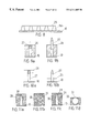
In FIG. 1 there is schematically illustrated a shaped charge in the form of a bomblet 1 at the point in time of striking against the surface 10 of an object which is to be protected. The bomblet 1 consists essentially of a housing 2, which is filled with an explosive 3 in such a manner that this explosive 3 will surround a downwardly opening insert 4 which is constituted of a material, for example, such as copper. The explosive 3 which is through-detonated by means of a fuze 6 presses the insert together at a high rate of speed so that, from the tip region of the insert 4, there is formed a hollow charge-jet or a jet 5. The insert 4 is thus deformed by means of the detonation of the explosive 3 into the jet 5 which moves under a continual stretching effect towards the surface 10 and penetrates into the latter. The peak velocities of the particles which form the jet 5 lie hereby between 5 and 8 kilometers per second (km/sec), whereas the diameter of the formed jet 5 lies within the millimeter range. At a complete precision, in a homogeneous steel armor there are attained penetrating depths which lie between 4 to 8 times the largest insert diameter. The mechanical impact detonation is effected, as a rule, in that a detonating needle 7 due to its inertia, upon striking against the object moves in a passageway 8 towards the fuze 6, and pierces the latter, as a result of which there is detonated the bomblet 1. The fuze 6 thereby brings the explosive 3 to detonation.
The power capability of the bomblet 1 depends essentially upon the stretching or expansion of the jet 5. This is achieved in that the originally quasi-homogeneous jet at the point in time of its formation is stretched and thereby caused to be particularized. A depth effect is then obtained from the addition of the individual powers of the individual particles forming the jet 5, which must penetrate behind each other in an absolutely precise manner. The stretching of the jet 5 takes place continuously, whereby the distance between the particles from the tip in the direction of the bomblet 1 continually reduces. For a desired penetrating power it is necessary to provide a specific stretching path 9, which is generally designated as a stand-off. The stand-off 9 is formed by the distance of the lower conical boundary of the insert 4 to the surface 10.
For impact detonators which necessitate a sufficient delay for their operational activation, the stand-off 9 in comparison with the diameter of the insert 4 of the bomblet 1 is formed small due to constructional requirements (referring, for example, to FIG. 1). For warheads with proximity fuzes, or with electrical triggering the stand-off 9 can be formed correspondingly larger (approximately 2-times the diameter of the insert).
Over a long period of time until now there has not been available any effective capability for protection against shaped charges, such as bomblets which approach or position themselves on an object.
SUMMARY OF INVENTION
Accordingly, it is an object of the present invention to provide an arrangement affording protection against shaped charges, such as primarily bomblets.
The foregoing object is inventively attained through the intermediary of an arrangement in which the surface of the armoring of the object which is to be protected has disruptive bodies associated therewith, whose height, shape and arrangement are dimensioned such that at least one such body, for the disruption of the jet formation of the shaped charge, can penetrate into an internal region of a hollow charge insert or into the so-called stand-off region of the shaped charge.
The principle of the arrangement pursuant to the invention is predicated on that the formation of a symmetrical jet of a bomblet can be prevented, and thereby the power thereof is able to be quite significantly reduced. This is preferably implemented through the penetration of at least one disruptive body into the internal region of the hollow charge insert and/or into the region of the insert opening.
Through the introduction of the disruptive body into the internal region or at least into the lower central region of the shaped charge, the jet is disrupted already at the beginning of the stretching thereof and prior to the jet being fully formed in a particular advantageous manner, in that the final ballistic power capacity of the hollow charge is reduced up to a fraction of its maximum power capability. Comparable power reductions can be achieved with no other of the measures known from the standpoint of the target in the practice, and also not with the most modern dynamic methods.
BRIEF DESCRIPTION OF THE DRAWINGS
Exemplary embodiments of the invention are further elucidated hereinbelow with reference to the drawings; in which:
FIG. 1 illustrates components of a shaped charge in the form of a bomblet for attacking from above an object which is to be protected;
FIG. 2 illustrates the subdivisions of the different effective zones of that type of charge;
FIG. 3 illustrates different positions of disruptive bodies;
FIG. 4 illustrates a zone A with further differently configured disruptive bodies;
FIG. 5 illustrates a zone B with further examples of differently configured disruptive bodies;
FIG. 6 illustrates the zones B and C with further examples of differently configured disruptive bodies;
FIGS. 7a through 7 c illustrate schematic representations of the deviation of the jet from its ideal line in dependence upon the position of the disruptive body which is introduced into the insert;
FIG. 8 illustrates a plurality of disruptive bodies which are provided with a covering;
FIGS. 9a and 9 b illustrate depressed or, respectively, partially outwardly extended disruptive body;
FIGS. 10a and 10 b illustrate, respectively, the release of disruptive bodies through the deflecting back of a surface;
FIGS. 11a through 11 d illustrate examples for a disruptive body which is embedded in a matrix or, respectively, a matrix which is equipped with disruptive bodies;
FIGS. 12a and 12 b illustrate the penetration of a target material located on the surface of the object which is to protected in the interior region of a shaped charge;
FIGS. 13a and 13 b illustrate movable slender disruptive bodies;
FIGS. 14a through 14 c illustrate a schematically represented anchoring of different movable slender disruptive bodies;
FIGS. 15a through 15 b illustrate an apertured plate which is equipped with disruptive bodies, as well as a apertured plate which is correlated with an armoring and fastened thereto;
FIGS. 16 illustrates a schematic representation wherein a disruptive body penetrates a casing protecting the insert;
FIG. 17 illustrates disruptive bodies which are fastened by means of a foil;
FIGS. 18a and 18 b illustrate a schematic representation of grid-like coverings from above of the surface of the object which is to be protected;
FIG. 19 illustrates an optimized armoring which connects itself to the disruptive bodies;
FIGS. 20a through 20 c illustrate a comparison of different protective principles;
FIG. 21 illustrates a protective module carrying disruptive bodies with connecting elements;
FIG. 22 illustrates a protective module with movable coverings and resiliently formed disruptive bodies;
FIGS. 23a and 23 b illustrate a thin surface structure with jet-disruptive properties;
FIG. 24 illustrates modular elements for the receipt of disruptive bodies;
FIGS. 25a through 25 c illustrate grids with knots for the receipt of disruptive bodies, and a knot in an enlarged view;
FIG. 26 illustrates adjacent modules with edge and joint protection through disruptive bodies;
FIG. 27 illustrates adjacent modules having joint bridging elements with disruptive bodies;
FIGS. 28a and 28 b illustrate disruptive bodies which are extendable by means of a bellows, whereby the bellows remains in the armoring;
FIGS. 29a and 29 b illustrate disruptive bodies which are extendable by means of the bellows, whereby the bellows projects above the armoring;
FIG. 30 illustrates telescopably configured disruptive bodies;
FIG. 31 illustrates disruptive bodies which are outwardly and again inwardly movable by means of a bellows;
FIG. 32 illustrates the influence the disruptive distance from the surface of the object which is to be protected.
FIG. 33 illustrates disruptive bodies which are outwardly extendable by being controlled from a proximity sensor; and
FIG. 34 illustrates an active arrangement for protection against approaching threats.
DETAILED DESCRIPTION OF PREFERRED EMBODIMENTS
For an explanation of the individual modes of the effect and capabilities of the herein described arrangement,there is implemented a subdivision of the region of the insert 4 inclusive the stand-off 9 into three zones. In FIG. 2, these are designated with zone A for the lower conical region and the stand-off 9, zone B for the middle region of the insert 4, and zone C for the tip region of the insert 4, which is arranged on the side of the insert 4 facing towards the fuze 6.
In FIG. 3 there is represented a bomblet 1 which is located on the surface of an armoring 10. Thereby, illustrated are a plurality of effective centers of gravity 14A, 14B, 14C, 14D, 14E, 14F of possible disruptive bodies in characteristics positions in an interior 129 of the insert 4. The effective centers of gravity of the disruptive masses or disruptive bodies are in the different geometrical embodiments of the disruptive bodies not identical with the actual centers of gravity of the masses. These designate primarily the location at which the disruptive body causes its greatest disruption of the jet. The connection between the effective centers of gravity 14A through 14F and the surface of the armoring 10 the object which is to be protected is effected either through a special arrangement, or presently through the disruptive bodies; for example, such as the disruptive bodies 16A through 16G, 17, 18 and 19 themselves. For assisting in the orientation, there is illustrated the direction of movement of the bomblet 1, its axis of symmetry 11, the collapsing point 12, and the forming jet tip 13. The already deformed portion of the insert 4 is designated with 4A.
The locations of the different effective centers of gravity 14A through 14F which are illustrated in FIG. 3 and thereby emphasized, the main disruptive center of gravity 14A is located at the inner wall of the cladding (insert) 4. In the location of the effective center of gravity 14B, the disruptive body projects until it reaches into the upper region of the insert 4, in the location of the center of gravity 14C in the middle region of the insert 4 outside of the axis of symmetry 11. Correspondingly, the disruptive body in the position 14D in the lower central region of the insert 4 is arranged proximate the axis of symmetry 11, and at the location of the center of gravity 14E, the disruptive body acts in the region of the stand-off. A special instance represented by the location of the effective center of gravity 14F. Here, the disruptive body mechanically pierces through or deforms the insert 4.
In FIG. 4 there is schematically illustrated the region of the insert 4 of the bomblet 1, as well as the zone A, and as well as; for example, disruptive bodies 16A, 16B, 16C, 16D, 16E, 16F, 16G. Hereby the disruptive bodies 16A through 16G are formed as different geometric bodies. Individually, the disruptive body 16A cylindrical, the disruptive body 16B rod-shaped, the disruptive body 16C spherically shaped, the disruptive body 16D cylindrical with a frusto-conical tip, the disruptive body 16E cylindrical with a rounded-off tip, the disruptive body 16F as a sharp tipped cone, and the disruptive body 16G as a truncated cone. All of the illustrated rotationally disruptive bodies can also be constructed cornered or symmetrical multi-sided; for example, as quadrats truncated pyramids, in the event that these due to reasons of signature conditions (radar detection) are considered as being advantageous. It lies within the scope of one skilled in the art that the embodiments illustrated in FIG. 4 for a disruptive body can also be employed for the desired effective centeis of gravity 14D and 14E of the disruptive bodies which are schematically illustrated in FIG. 3.
FIG. 5 illustrates a few embodiments of disruptive bodies, which evidence a such a length that these project into the zone B of the insert 4. Hereby, a disruptive body 17A is constructed as a hollow cylinder, which in the present examplary embodiment is filled with a medium 17B. The disruptive body 17A can also be simply constructed as a hollow body without any filler medium. The disruptive body 18A is constructed rod-shaped and can similarly possess hollow space 18B and/or also a tip 18C.
The disruptive body 18A, pursuant to a further embodiment which deviates from the foregoing exemplary embodiment, can be constructed solid and without a tip.
A disruptive body 19A which is illustrated in FIG. 5 is cylindrical and formed with a rounded-off tip 19B, whereby the basic cylindrical body is connected by means of a trunnion 19C with a rounded-off tip 19B. A disruptive body 20A is configured as a truncated cone which; for example, by means of a trunnion 20B is fastened in the surface of the armoring 10 of the object to be protected as a carrying or support structure.
The disruptive body 17A represents a specialized embodiment of the effective centers of gravity 14C and 14D illustrated in FIG. 3. The same as applicable to the disruptive body 18A which represents a specialized form of the effective centers of gravity 14B and 14C pursuant to FIG. 3. The disruptive body 19A represents a specialized exemplary embodiment of the effective center of gravity 14E pursuant to FIG. 3, and the disruptive body 28A for the effective center of gravity 14A pursuant to FIG. 3. Naturally, the transitions between between the individually represented embodiments of the disruptive bodies is variable, and can be contemplated by a multiplicity of combinations thereof.
In FIG. 6 there is illustrated the zone C of the insert 4, whereby rod-shaped disruptive body 23 is constructed in such a manner that it penetrates into the zone C, and in its principle embodiment corresponds to the effective center of gravity 14B of FIG. 3. Moreover, the combination of a rod-shaped disruptive body 23 with a conically constructed basic disruptive body 23B is illustrated by way of example. This combination concurrently causes disruptions of the jet 5 in the zones A, B & C, as is schematically represented in FIG. 3 by means of effective centers of gravity 14B, 14D and 14E. A particularly interesting instance of disruption is illustrated in FIG. 6. This disruptive body 21, which in this exemplary embodiment is formed as a cylindrical disruptive body, penetrates the insert 4 of the bomblet 1 which strikes against the surface of the armoring 10. As a result thereof, there is produced a greater deformed or disrupted zone 22, which upon the through detonation of the explosive 3 leads to particularly outstanding disruptions of the jet 5.
At this juncture it should be pointed out that the representative examples for disruptive bodies cause not only the jet disruptions with regard to their effective centers of gravity, but also that the connections to the surface of the armoring 10, such as connectors, casings, and so forth, cause further timely disruptions which extend over a greater spatial region.
FIGS. 7a through 7 c illustrate three examples of typical jet disruptions corresponding to the positions of the effective centers of gravity 14A, 14B, 14C, 14D, and 14E. The jet disruption illustrated in FIG. 7a, which is represented by the phantom line 24A is initiated by the position of the effective center of gravity 14B. Thereby, the effective center of gravity 14B of the disruptive body is presented in a considerably schematic manner as a black circle, which represents the interior region 129 of the insert 4 which is reached by the end of the disruptive body.
Inasmuch as the lower rapid portion of the jet which provides for the highest power component during the penetration of the armoring of the object which is to be protected, is formed by the tip of the insert 4, in this part, meaning within the zone C the disruption by means of a disruptive body is at its most intense. In addition, to the already mentioned disruption through the connections of the disruptive bodies and of the armoring 10, due to shock-wave reflections in the explosive and in the region of the insert 4, the introduced disruption also propagate into the following regions, so that the disruption of the jet does not remain restricted to only this region. This consideration, for the remainder is applicable to all further illustrated and described examples.
The jet disruption illustrated in FIG. 7b, which is graphically represented by the phantom-line 24B, is caused through the disruptive bodies with the effective centers of gravity 14A and 14C which are brought into the interior region 129 of the insert 4. There is achieved a further deflection of the middle portion of the jet 5.
The jet deflection illustrated in FIG. 7c, pursuant to a phantom-line 24C is caused by the entry of the disruptive bodies with the effective centers of gravity 14D, 14E into the interior region 129 of the insert 4. The disruptions in the formation of the jet 5 here remains concentrated primarily on the rearward portion of the jet, whereas the disruptive body with the effective center of gravity 14D due to its symmetrical axis-proximate position causes awaiting still further disruptions in the forward portions of the jet. Understandably, from the most different combinations of the locations of the center of gravity, as well as the embodiment of the outer form, and as well as the jet disruption corresponding to the length of the disruptive bodies, which as a rule add to each other since they basically support the asymmetry.
In the event that robust or relatively simply structured surfaces are to be implemented, one can be employ short, thick disruptive bodies with effect in the region of zone A. By means of these, for example, there can be realized accessible surfaces. Such measures correspond to the example illustrated in FIG. 7c, whereby the effect combines itself from a number of factors, when concurrently a plurality of disruptive bodies can be placed in the interior region of a striking bomblet 1, or when a central disruptive body leads to a concurrent asymmetrical disruption of the stretching hollow charge jet.
Should there be realized flat surfaces of the object which is to be protected, then, for example, as illustrated in FIG. 8 and as truncated cone configured dissruptive bodies 16F can be contemplated with a covering 25. Then, there is merely to be considered that this covering 25 does not prevent the further sinking down of the charge up to its detonation, in effect, the covering should not be constructed two massively. Just as well, it is possible to configure the covering 25 to be removable, so that it is first removed in a serious instance. Such types of coverings are then of particular interest when there is desired a specified signature behavior of the surfaces. It is also possible through specific forms and materials to impart to the disruptive body-supporting surface an advantageous signature phenomenon.
In FIG. 9a, 9 b and 1Oa, 10 b there are dynamically built up disruptive zones in accordance with need. Thus, in the example illustrated in FIGS. 9a, 9 b, the disruptive bodies 27 are outwardly extended or justified from the surface 26 of a suitably constructed target. Thereby, in FIG. 9a the disruptive body is illustrated in the retracted position and in FIG. 9b in a partly outwardly extended position.
FIGS. 10a and 10 b illustrate an alternative embodiment in comparison with FIGS. 9a and 9 b, whereby a surface 26 which originally covers the disruptive body 27 deflects back into the illustrated direction of the arrow (FIG. 10a) and thereby releases the disruptive body 27 (FIG. 10b).
In FIGS. 11a to 11 b there are illustrated a few special embodiments of target with the above-mentioned protective properties, whereby on the surface of the armoring (remaining or follow-up armoring) 10 of the object which is protected, there are applied disruptive bodies which cause the desired disruption of the jet. Thus, FIGS. 11a through 11 b illustrate examples of disruptive bodies which are embedded in a relatively soft, yieldable matrix 30. In FIG. 11a, for example, there is positioned in a defined manner a conical disruptive body 28 in that type of material. In FIG. 11b, spherically-shaped disruptive bodies 29 are emerged in a regular or irregular distribution within the matrix 30. In FIG. 11c, there is represented a combination of the embodiments of the disruptive bodies 28 and 29 as illustrated in FIGS. 11a and 11 b. In FIG. 11d, the matrix 30 is constructed as a positioning or embedding layer for a spherical disruptive body 31 which is not completely encompassed by the matrix 30. That type of matrix 30 can; for example, be constituted foamed of a material or a deformable polymeric material.
In FIG. 12, a layer 32 which is positioned in front of the surface 10 of the object which is to be protected, consists of a material which is constructed sufficiently yieldable so that during the penetration of the bomblet 1 it is accelerated into this layer 32 in a direction of the insert 4, as is illustrated by an arrow 33. Thereby, introduced into the interior region 29 of the insert 4 is a disruptive body 34 consisting of the material of the layer 32 for causing the disruption of the jet formation.
As already indicated, disruptions in the region of zone C, in effect in the tip region of the insert 4 are basically especially effective. In order to reach the zone C during the striking of the bomblet 1, there are expediently employed slender disruptive bodies, such as are illustrated, for example, in FIG. 6. In FIGS. 13a and 13 b there are illustrated examples of such disruptive bodies 35. The object which is to be protected in FIG. 13a at the surface of the armoring 10, which is equipped with the disruptive bodies 35, the approaching bomblet 1 slides one (as illustrated) or a plurality (not illustrated) of the disruptive bodies 35, in dependence upon the distribution density, into the interior region 129 of the insert 4, and bends the disruptive body 35 into a shape which shown in FIG. 13b as represented by 36.
In FIGS. 14a and 14 b there are illustrated two further examples of the manner in which by means of slender disruptive bodies 35 there can be reached the tip region of the insert 4 of a striking bomblet 1. The condition illustrated in FIG. 14a corresponds to the example illustrated in FIG. 13b. The disruptive body 35 is constructed to be bendable so that it can be brought into the shape illustrated by 36. Pursuant to FIG. 14b the disruptive body 35, as illustrated at 37, fixedly mounted in the surface of the armoring 10. Alternatively, to the bendable embodiment of the disruptive body 35, the disruptive body 35 can be rigidly constructed and by means of a turning device 39 moveably supported in the surface of the armoring 10 and bringable into the outwardly extended positions 38. The turning device 39, by way of example illustrated in FIG. 14c, can be; for instance, can be constituted of a housing 40 which is filled with an elastomeric material, which is embedded in the surface of the armoring 10.
Basically, the layer carrying the disruptive bodies can be modularly assembled. It can also be advantageous to cover curved surfaces with such kinds of disruptive layers. FIG. 15a discloses, by way of example, an apertured plate 41 in which there are fastened disruptive bodies 42. In this case,there are represented two basic disruptive body shapes, firstly, a slender embodiment pursuant to the disruptive body 16B of FIG. 4, or the disruptive body 18A according to FIG. 5, and a conical configuration according to the disruptive body 16F or 16G as in FIG. 4. In FIG. 15b a support layer 44 consists of a hollow structure which carries the disruptive bodies 42. This structure, following the curvature of the supportive armoring 43, is connected by means of a fastening element (not shown) or a schematically represented fastening layer 45 with the supportive armoring 43.
Pursuant to a particular embodiment, a protective surface of that type can also be constituted of apertured sheetmetal strips with one or more rows of disruptive bodies.
Inasmuch as it is also possible to contemplate that the insert 4 of a striking bomblet 1 is equipped with a covering 46, it is throughout possible that by means of a correspondingly constructed disruptive body 130, which in principle corresponds with the disruptive body 21 as in FIG. 6, to push through the covering 46 and to penetrate into the interior region 129 of the insert 4. This is illustrated in principle in FIG. 16 of the drawings.
A particular configuration of a disruptive layer built by a plurality of disruptive bodies 47A, 47B is illustrated in FIG. 17. Hereby, the disruptive bodies 47A, 47B are fixed on a support plate 49 by means of bores 48, and encompassed by a casing layer 50 which, for example, is applied under the effect subatmospheric pressure, such as would be a deep-drawn foil, onto the disruptive bodies 47A, 47B.
FIGS. 18a and 18 b illustrate, respectively, a covering of the surface of the armoring 10 with disruptive bodies 51 and 52, whereby these are arranged in such as manner that one or more of the disruptive bodies 51, 52 can simultaneously penetrate into the interior region of a bomblet, which is schematically indicated by means of the circles.
FIG. 19 illustrates an example for an expedient substructure below a layer with disruptive bodies. An exactly oriented high-powdered jet is essentially easier to disrupt by means of dynamically especially effective devices such as bulging structures then would be an already intensively dispersed jet. It is accordingly sensible that the jet which has been disrupted in a preceding zone 53, can be caught in a ballistically especially effective back-up armoring 54, such as is formed generally of a high-strength steel or ceramic. A back-up armoring or layer 54 can then, for example, be fastened on a supportive armoring 56 by means of a damping layer 55 which is also adapted for the further dispersion of residual jet portions still exiting behind the layer 54.
In FIGS. 20a through 20 c there are comparatively represented three target constructions. Thus, FIG. 20a illustrates a homogeneous steel armoring 57 which is still to be penetrated by the bomblet 1 (limit of penetration). The reference mass in a reference height H1 here consists of presently 100%, which corresponds to the value 1.
In FIG. 20b the same bomblet 1 penetrates still further through a high-strength special armoring 58 of usual structure. The height H2 thereof corresponds with somewhat the height of the solid armoring 57, whereby its mass consists of only one-third that of armoring 58. In FIG. 20c there are represented two protectively equal armor structures with disruptive bodies 59A and 59B. Their total height H3 should be one-half the height H1 of the homogeneous armoring. At an assumed ratio of disruptive range height to back-up armoring of 1:4 for the right-hand example (relative solid disruptive bodies), there is obtained in the center a one-quarter of the mass of the homogeneous steel target. In the left-hand example, there are employed slender, thin disruptive bodies, which allow for a ratio between the disruptive range height and back-up armoring of 2:1. Thereby, the mass reduces itself to one-sixth the mass of the homogeneous steel target.
In an unusual manner the power capability of a protective arrangement is given by means of the product from mass efficiency, which corresponds with the ratio of the penetrated target mass of a steel armoring in limiting penetration to the penetrated target mass of the considered target, and the spatial efficiency which, in turn, again correspond to the ratio of the thickness of the steel armoring which is penetrated in the limiting penetration, relative to the thickness of the intended target. The example illustrated in FIG. 20a provides as a reference a product of 1, whereby contrastingly the special armoring 58 pursuant to FIG. 20b produces a product of three, and the structure pursuant to FIG. 20c which is equipped with disruptive bodies produces a product of eight for the right-hand example and of 12 for the left-hand example. That type of total effectiveness is not achieved or even approached by any of the other inert armoring which is known from the state of the technology.
The above comparative observation leads then to further significantly higher value numbers when the disruptive structure operates with slender disruptive bodies extending far into the insert 4, or when the disruptive bodies are set further apart and/or possess a lower mass. Since the disruption of the jet can be attained in accordance with the position of the disruptive body with practically every material, it is possible to achieve a multiplicity of extremely mass-efficient solutions.
Experimental studies which have been carried out in the interim, lead to the conclusion that highly effective disruptions can also be achieved when the mass centers of gravity of the disruptive bodies are located approximately between the upper third and the middle of the insert 4. This simplifies the construction of optimally acting structure with disruptive bodies.
It can often be expedient to modularly build up a protective structure of the proposed type. An example of that type is represented in FIG. 21. On the left-hand side, disruptive bodies 16G are mounted on a surface of the armoring 10 of the object which is to be protected. On the right-hand side there should be integrelly constructed disruptive bodies 60 with the surface of the armoring 10 of the object which is to be protected. The individual modules which form the protective surface are connected through connecting elements 61, which also allow for a certain movability of the thus produced connections.
A particularly advantageous technological solution of the herein proposed principle represents due to their in height variable disruptive bodies, such as; for example, those represented in FIG. 22. In a correspondingly configured support element 62, there are located spring-like disruptive bodies 63 which are retained in a chamber 131, by means of a moveable covering 65. When the coverings 65 are removed from the chamber 131, the disruptive bodies 63 are unstressed and then allow to expand. Thus, in FIG. 22 there is illustrated an unstressed disruptive body 63A. In order to provide an efficient disruption of the jet by an expedient effective center of gravity, the disruptive body 63 or 63A can be equipped with an additional disruptive mass 64 which is arranged at its end distant from the support elements 62.
This principle of a highly changeable disruptive body can be implemented in different manners. Thus, it is also possible to contemplate rubber-like disruptive bodies which can be folded bellows-like. Also, metal springs fulfill this task. The variation in the height can also be achieved by a laying down of resilient disruptive bodies, which can be resiliently uprighted when needed.
Two further technologically interesting constructional forms of the arrangement are represented in FIGS. 23a and 23 b. Here, the jet-disruptive surface is realized by means of thin structures. In FIG. 23a, the surface of the armoring 10 object of which is to protected carries a thin structure, which contains disruptive bodies 66 for an early jet disruption. Such type of structures; for example, can be constituted of relatively thin metallic plates, of fiberglass reinforced plastic materials or polymers, which are cast, deep drawn, stamped, punched or compressed. FIG. 23b illustrates a further surface profile 67, whereby there are provided disruptive bodies possessing different lengths and shapes. It is also possible to contemplate additionally introducing masses into the upper region of the disruptive bodies 66, 67 in order to improve upon the disruptive effect.
For the utilization there can be also of interest such installations which are modularly assembled and into which there can be inserted the desired disruptive bodies. FIG. 24 discloses two modules 68 with corresponding receivers 69. Hereby, this can relate to metallic support modules, as well as also those consisting of plastic, rubber, fiber-glass-reinforced plastic, or the like. Non-planar surfaces can be considered as being carried either through a modular configuration or through bendable support materials.
In FIGS. 25a through 25 c there is further carried out the above-described principle with regard to a flexible configuration. Thereby this relates to a grid-like support structure 70, which preferably possesses in the knots or nodules therof receivers 71 for disruptive bodies. FIG. 25b illustrates a receiver 71 located in a kuat in plan, view shown in an enlarged representation. An inserted disruptive 72 is fastened, pursuant to FIG. 25c, by means of a projection or trunnion 73 in the receiver 71. That type of principle is adapted for the receipt of suitably shaped disruptive bodies in the most widely differing kinds of materials, or also for the exchanging of disruptive bodies; for example, against different types of threats.
It is also possible to contemplate that the examples of disruptive bodies or support layers for disruptive bodies which are represented in FIGS. 12, 23, 24 and 25 are constructed so thin or soft, that they possess outstanding damping properties. As a result, it is clearly contemplatable that also those with relatively high speeds or steeply descending speeds posing threats can be caught softly or resiliently, so that there is not at all produced any detonation of the bomblets.
A further advantage or relatively yieldable thicker disruptive bodies of support layers for disruptive bodies can consist of in that any threats prior to their detonation are permitted to enter relatively deeply. This is of advantage when the bomblet is equipped with a fragmentation casing, which concurrently accerates fragments with the formation of the hollow charge jet by means of the detonating explosive in a lateral direction. These will then be at least in an immersed part, absorbed by the disruptive bodies or support layer.
A particular advantage of the herein described arrangement for the disruption of hollow charge jets during their formation consists of in that, hereby in particular, there can be avoided weak points of protective structures. This is elucidated in the exemplary embodiments of disruptive bodies illustrated in the following described drawing figures.
Thus, FIG. 26 illustrates four (4) protective modules 74. The disruptive bodies 75, 77 are here basically arranged in such a manner that there is reinforced a critical edge region or impact region between the protective modules 74. This can be effected in that the individual protective modules 74 possess disruptive bodies in their edge regions, or that disruptive bodies are directly integrated into the impact region. This is represented; for example, in FIG. 26 through the section X—X. This illustrates a bar 76 inserted between the protective modules 74, which contains applicable disruptive bodies 75, which are connected by means of connectors 75A with the bar 76. This bar 76 can also serve as a buffer element between the protective modules 74 or some other secondary functions (such as; for example, fixings). FIG. 26 also illustrates an example of the manner by which a central disruptive body 77 in the impact region of a plurality of protective modules 74 can attain a decisive increase in protective power.
In FIG. 27 there are illustrated further examples for avoiding weak locations of modular armorings by means of disruptive bodies. Thus, the edge regions of protective modeule 74 can be either reinforced through a one-sided edge bar carrying disruptive bodies or a lash 78, assembling two (2) modules and in the edge regions themselves covering bars or lashes 79, 80, or by covering the impact region of a plurality of protective module 74 through impact plates 81 carrying dissruptive bodies, thereby increasing the protection.
The edge bar or lash 78 is hereby especially provided for the outer region of the support layers to which no further support layer is connected. The bar or lash 79 is constructed relatively wide and possesses two adjacently arranged rows of disruptive bodies. Alternatively thereto, the bar or lash 80 is constructed so as to only possess a single row of disruptive bodies. The impact plate 81 layer is of a quadratic or round basic shape and provides the support for four (4) disruptive bodies. Basically,in accordance with need, the disruptive bodies can be constructed of any suitable geometric form, such as for example, spherically, cylindrically, conically or pyramid-shaped and designed differently in length or height. The disruptive bodies can be constituted of metallic materials, polymeric materials, glass or ceramic, fiber glass-reinforced plastics, of pressed members, cast members and/or of foamed materials.
On the basis of FIGS. 9 and 10, there is illustrated the instance in which the disruptive zones can be dynamically built up. FIGS. 28a through 31 illustrate hereby a series of technological types of solutions. Thus, in FIG. 28a in an armoring 82 there is integrated an arrangement for protection against shaped charges, whereby, upon need, by means of a bellows 84 and a carrier or support plate 85, there can be extended disruptive bodies 90 from a chamber 83. A closed covering 93 of the arrangement is here effected through an apertured plate 91, whose bores 92 are associated with the disruptive bodies 90. As an outer covering 93 there can serve a thin plate or foil which; for example, can be pierce through by the disruptive bodies 90. Such a covering 93 can also assume a specialized function with regard to the signature.
The bellows 84 together with the carrier plate 85 encloses a pressure chamber 86. When, for instance, by means of an element 87 which generates a gas, which is controlled through a conduit 88, there is released a working gas, then the disruptive bodies 90 are pushed out of the upper surface of that the protective structure. It is also possible the working gas is conducted directed through a bore 89 into the pressure chamber 86.
In the example illustrated in FIGS. 28a and 28 b, the movement of the disruptive bodies 90 is limited by means of the plate 91. However, it is also possible to contemplate embodiments in which disruptive bodies can be pushed out relatively far from relatively flat protective arrangements by means of movable platforms. For this purpose, FIGS. 29a and 29 b illustrate an exemplery embodiment. With consideration given to FIGS. 28a and 28 b, there is again effected the outward extension of disruptive bodies 95 from a module 94 by means of a bellows 84. The module 84 is closed off by a layer 96. Upon need, by means of this arrangement there can be introduced into the pressure chamber 86 a working medium, such as; for example, a working gas, so that the volume 86A of the pressure chamber 86 is significantly increased and the bellows 84, as represented in FIG. 29b, is outwardly extended. Hereby, there can be achieved relatively large lifting heights HuH at 97.
In FIG. 30 there is illustrated the instance in which individual disruptive bodies can be extended from a protective structure. At the left-hand side, by means of a superatmospheric pressure in the in feed line 102 and in the bore 103 there is moved a disruptive body 100 in a piston 99. The base piece 101 serves as a seal and lift limiter. The height of the disruptive body 100 thereby determines in a first instance, the reachable lifting height HuH of 97. It is also contemplatable that with that type of arrangement by means of superatmospheric pressure or subatmospheric pressure the disruptive body 100 can be outwardly moved or inwardly retracted. At the right-hand side in FIG. 3 there are extended telescopable disruptive bodies. Hereby, by means of a piston 104 there is moved a second piston 105, in which there is movable an end member 100A. The introduction of the working gas is carried out through the bores 103 and 103A. By means of this telescoping principle it is possible to achieve a relatively large lifting height HuH at 97A.
FIG. 31 illustrates a technical construction for the outward ejection of individual disruptive bodies 110 from a protective structure 107, which is either eposed or covered by means of a layer 111. In accordance with the preceding two examples, and alternatively to FIG. 22, the outward displacement and the retraction of the disruptive bodies is effected through a working gas. A bellows at 109 is thereby represented in the retracted condition and at 109A in the outwardly extended condition.
Quite generally, power of shaped charges, as previously mentioned is determined through the stand-off, in effect, the distance of the edge of the insert from the surface of the structure which is to be protected. Charges for initiating an attack from above, the so-called bomblets 1, distinguish themselves as a rule in that already at a small-stand off, they achieve the desired penetrating power. However, also their penetrating power grows upon an increase in the stand off. The herein proposed principle in employing the effect of disruption of the jet formation or the jet disruption while still in the region of the insert, is in a special manner adapted such that the final ballistic power of shaped charges also at larger stand-offs are significantly reduced. The cause for this is represented in FIG. 32. Considered is a relatively small stand-off 113A of the bomblet 1 to the surface of the armoring 10 of the object which is to be protected in comparison with a relatively larger distance 113B. It is assumed that the center of gravity 112 in the effectiveness of the disruptive body will disrupt the forming jet in such a manner that upon reaching of the somewhat proximate surface of the object which is to be protected, the jet already evidences a lateral deflection 114A. As previously mentioned, due to the deflection of the jet particles from the axis, the penetrating depth 117A is already extensively reduced at an increase in the crater diameter 116A.
When the surface of the armoring 10, at the same disruption, is at a considerably greater distance 113B, then the jet 114A is stretched and also directed inwardly at a greater lateral deflection 114B. This leads to a further significant reduction in the penetrating depth 117B at a concurrent increase in the crater diameter 116B. Inasmuch as in the two (2) illustrated examples, the displaced crater volumes 115A, 115B are comparable due to energetic reasons, there is obtained a physically final explanation for the reduction in the penetrating depth.
It is also quite possible to contemplate that disruptive bodies in accordance with the proposed solution can be extended or raised up from the surface of the armoring 10 by means of a sensor and corresponding installations upon sensing the approach of a threat. FIG. 33 illustrates an example for such a type of “active” solution. In this case, the approaching bomblet is detected by a proximity sensor 118, as is illustrated by means of a phantom double-headed arrow 119. This sensor 118 transmits on impulse through a line 120 to a control unit 121 which, in turn; for example, through a connection 122 is connected with a gas-operated arrangement or the pressure chamber 86 pursuant to FIGS. 28a, 28 b or 29 a, 29 b. Naturally, the outward displacement can also be effected through other techniques. As examples there can serve electro-magnetic installations or also simple mechanical arrangements, such as springs.
FIG. 34 illustrates a further example of an active protective arrangement for the ejection of disruptive bodies against approaching threats, such as hollow charges. In this exemplary embodiment, a target structure 123 contains individual acceleration chambers 98 which are provided with a covering 111, corresponding to the description of FIG. 31. A proximity sensor 124 is interlinked with an individual or with groups of defensive installations through the control element 126, and detects approaching threats, such as bomblets 1, in regions which are represented by 125. The outwardly displaced and, in this example, the disruptive bodies 110 which leave the target structure fly along a relatively short path, whose direction is identified by the arrow 127, opposite towards the bomblet 1 through the bores or the receiver of the acceleration chamber 98. In this manner, it is possible by means of a suitable combination of groups of disruptive bodies, to afford that at least always one disruptive body will penetrate into the approaching threat (bomblet) and decisively disrupt the formation of the jet.
At their ends facing away from the surface of the armoring 10 of the object which is to be protected, the disruptive bodies of all previously described exemplary embodiments can be constructed concavely, convexly, planar or pointy. Just as well, their side flanks can be constructed at right angles or at an acute angle linearly relative to the surface of the armoring 10. Similarly, it is also possible to impart a curved surface to the sides of the disruptive bodies.
In order to guarantee the most possibly efficient disruption of the jet, and to maintain the weight of the object which is designed to be protective as low as possible, there must be considered an optimum mass distribution during the configuring of the disruptive bodies. In principle, it is expedient for the jet disruption when the disruptive bodies are correlated essentially with the shape of the insert, which is mostly conically or in a trumpet shaped form. This signifies that the further the disruptive bodies penetrate or enter into the interior region of the insert 4, the less mass is required, especially in the end region of the disruptive bodies, for an effective disruption of the jet formation. In the region of the surface of the object which is to be protected there is required more mass for the disruption of the jet formation, so that essentially at a mass and effectiveness optimized disruptive body there is obtained a profile which is similar to the Ganssian normal distribution curve.
Pursuant to another herein not specifically represented embodiment of the protective arrangement, there can be made provision that the disruptive bodies are movably arranged in guide rails which facilitate a sliding of the disruptive bodies along the surface of the object which is to be protected. Accordingly, it is possible to effectively protect a large surface with only a few disruptive bodies. The arrangement of the disruptive bodies can similarly be controlled for movement along the surface of the object which is to be protected by a motion reporter or sensor arranged on the surface of the object.
The disruptive bodies can be fixedly connected with the surface of the armoring 10 of the object which is to be protected by means of adhesives, soldering, welding or press fitting.
Alternatively, there is also present the possibility to detachably connect the disruptive bodies with the surface of armoring 10 of the object of which to be protected by means of a screw connection or a plug connection. The disruptive bodies, in a particular embodiment, can consist of a combination of metallic, fiberglass-reinforced plastic materials, glass or ceramic, polymer films and/or foamed materials.
The wall thicknesses of metallic disruptive bodies can be lined in the magnitude of the wall thickness of the insert 4 at the disruptive location, whereby, however, also wall thicknesses for the disruptive bodies can be contemplated which deviate from the wall thickness of the insert 4. The average diameter of the disruptive body can be approximately two to five times that of the wall thicknesses of the insert 4 at the disruptive location.
For elongate disruptive bodies, for example, such as slender cylinders or springs among others, the diameter of the disruptive bodies can correlate in a particular configuration with the average wall thickness of the insert 4. When the disruptive bodies are formed of non-metallic materials, then the disruptive mass in the disruptive center of generally the mass can correspond with the mass which corresponds to the mass of the insert 4 at this particular location.

Claims (49)

What is claimed is:
1. An arrangement for protection against attack by shaped charges and bomlets which approach or seat themselves on an armored object, characterized in that a surface of the armoring of the object which is to be protected has disruptive bodies associated therewith, the height, form and arrangement are dimensioned so that at least one of said disruptive bodies, for the disruption of the formation of a jet from the shaped charge, can selectively penetrate into an interior region of a hollow charge insert of the shaped charge and into a stand-off region of the shaped charge.
2. An arrangement according to claim 1, characterized in that the disruptive bodies are geometric bodies and are arranged and constructed in a manner so as to form a quasi-planar and/or accessible surface of the armoring.
3. An arrangement according to claim 1 or 2, characterized in that between the disruptive bodies and the surface of the armoring of the object which is to be protected there is located a connector which retains at least one of the disruptive bodies into a specified position.
4. An arrangement according to claim 1, characterized in that the disruptive bodies in relationship to an inner diameter of the shaped charge are so thin as to be able to penetrate into an upper region of the hollow charge insert.
5. An arrangement according to claim 1, characterized in that the disruptive bodies are entirely or partially brittle and/or rigidly constructed.
6. An arrangement according to claim 5, characterized in that the disruptive bodies are constituted partially or completely of metallic materials.
7. An arrangement according to claim 5, characterized in that the disruptive bodies are constituted entirely or partially of fiberglass-reinforced plastic materials.
8. An arrangement according to claim 5, characterized in that the disruptive bodies are constituted entirely or partially of glass or ceramic.
9. An arrangement according to claim 1, characterized in that the disruptive bodies are constituted entirely or partially of polymer materials.
10. An arrangement according to claim 1, characterized in that the disruptive bodies are constituted entirely or partially of pressed members.
11. An arrangement according to claim 1, characterized in that the disruptive bodies are constituted entirely or partially of foamed materials.
12. An arrangement according to claim 1, characterized in that the disruptive bodies are constituted of a combination of materials selected from the group consisting of metallic materials, fiberglass-reinforced plastic materials, glass ceramic, polymer materials, pressed members and foamed materials.
13. An arrangement according to claim 1, characterized in that the disruptive bodies are constructed entirely or partially hollow.
14. An arrangement according to claim 1, characterized in that the disruptive bodies are filled with a medium.
15. An arrangement according to claim 1, characterized that the disruptive bodies are solidly constructed.
16. An arrangement according to claim 1, characterized that the disruptive bodies are equipped with a tip and are variably dimensioned in diameter along their lengths.
17. An arrangement according to claim 1, characterized that the disruptive bodies are fixedly connected with the surface of the armoring of the object which is to be protected.
18. An arrangement according to claim 17, characterized that the disruptive bodies are selectively connected with the surface of the armoring of the object which is to be protected through the intermediary of adhesives, soldering, welding or press fitting.
19. An arrangement according to claim 1, characterized in that the disruptive bodies are detachably connected to the surface of the armoring of the object which is to be protected.
20. An arrangement according to claim 19, characterized in that the disruptive bodies are screwed to with the surface of the armoring of the object which is to be protected or inserted therein by a plug connection.
21. An arrangement according one claim to claim 1, characterized that the disruptive bodies are movably supported on the surface of the armoring of the object which is to be protected.
22. An arrangement according to claim 1, characterized in that the disruptive bodies are arranged relative to the surface of the armoring of the object which is to be protected so as to project sutuerdly therefrom only upon need in case of a threat.
23. An arrangement according to claim 1, characterized in that the disruptive bodies are fixed through embedding thereof into a comparatively soft matrix which is arranged on the surface of the armoring of the object which is to be protected.
24. An arrangement according to claim 23, characterized in that the matrix contains the disruptive bodies in either a uniform or irregular distribution.
25. An arrangement according to claim 1, characterized in that the disruptive bodies are connected with a modularly assembled layer arranged on the surface of the armoring of the object which is to be protected, whereby the individual modules of the layer are interconnected with each other by connecting elements which facilitate a certain movability of the connection.
26. An arrangement according to claim 25, characterized in that the layer is constructed as an apertured plate or strips in which there are fastened the disruptive bodies.
27. An arrangement according to claim 25, characterized in that the disruptive bodies are mounted on the protective modular layer through the intermediary of a fastener element or a fastening layer.
28. An arrangement according to claim 27, characterized in that the fastening layer comprises an adhesive foil.
29. An arrangement according to claim 1, characterized by a layer formed of disruptive bodies, which is bendably constructed and correlated with the surface of the armoring of the object which is to be protected.
30. An arrangement according to claim 1, characterized in that the disruptive bodies, are constructed so as to deform and/or penetrate the hollow charge insert.
31. An arrangement according to claim 1, characterized in that the disruptive bodies are constructed to be able to penetrate a covering which is arranged infront of the interior region of the hollow charge insert.
32. An arrangement according to claim 1, characterized through the provision of disruptive body layers which are equipped with a covering.
33. An arrangement according to claim 1, characterized in that the disruptive bodies are outwardly displaceable from a layer surrounding the disruptive bodies.
34. An arrangement according to claim 33, characterized in that the layer contains suitably distributed disruptive bodies.
35. An arrangement according to claim 1, characterized by a layer surrounding the disruptive bodies which deflects in front of the shaped charge and thereby releases the disruptive bodies.
36. An arrangement according to claim 33, characterized in that the layer carries individual said disruptive bodies.
37. An arrangement according to claim 1, characterized in that the disruptive bodies are supported swingebly, resiliently or bendably in a turning device.
38. An arrangement according to claim 1, characterized in that an armoring which follows the disruptive bodies is correlated with a disruptive zone formed by one of the disruptive bodies and forms a connection therewith.
39. An arrangement according to claim 1, characterized in that the disruptive bodies are variable in their lengths.
40. An arrangement according to claim 39, characterized that the disruptive bodies which are variable in their lengths are mounted in chambers and the chambers are equipped with a movable covering.
41. An arrangement according to claim 1, characterized that the disruptive bodies are integrally formed with a layer.
42. An arrangement according to claim 1, characterized that a surface layer of the armoring is formed by a rigid or bendable matting with receivers for the disruptive bodies.
43. An arrangement according to claim 1, characterized that the disruptive bodies are at least partially formed as springs which possess at their ends distant from the surface of the armoring an additional disruptive mass.
44. An arrangement according to claim 1, characterized in that first upon the striking of the shaped charge formed on a relatively soft deformable target material or a layer which is located on the surface of the armoring of the object which is to be protected, in which the target material of the one part of the layer is pushed into the interior region of the hollow charge insert.
45. An arrangement according to claim 1, characterized at least a part of the disruptive bodies is formed as a rubber-like element which is bellows-like foldable.
46. An arrangement according to claim 1, characterized that the disruptive bodies are fixed on a support plate by means of bores and surrounded by a casing layer.
47. An arrangement according to claim 1, characterized in that on the surface of the armoring there is arranged a detection device.
48. An arrangement according to claim 47, characterized in that the detection device activates a protective module prosessing disruptive bodies.
49. An arrangement according to claim 48, characterized in that disruptive bodies are accelerated from one or more said protective modules against a threat from said shaped charges.
US09/197,029 1998-06-05 1998-11-20 Arrangement for protection against shaped changes Expired - Lifetime US6311605B1 (en)

Applications Claiming Priority (2)

Application Number Priority Date Filing Date Title
DE19825260 1998-06-05
DE19825260A DE19825260B4 (en) 1998-06-05 1998-06-05 Arrangement for protecting objects against shaped charges

Publications (1)

Publication Number Publication Date
US6311605B1 true US6311605B1 (en) 2001-11-06

Family

ID=7870082

Family Applications (1)

Application Number Title Priority Date Filing Date
US09/197,029 Expired - Lifetime US6311605B1 (en) 1998-06-05 1998-11-20 Arrangement for protection against shaped changes

Country Status (12)

Country Link
US (1) US6311605B1 (en)
EP (1) EP1002213B1 (en)
AT (1) ATE326678T1 (en)
AU (1) AU4372999A (en)
CA (1) CA2300272C (en)
DE (1) DE19825260B4 (en)
DK (1) DK1002213T3 (en)
ES (1) ES2264260T3 (en)
IL (1) IL134375A (en)
PT (1) PT1002213E (en)
TR (1) TR200000811T1 (en)
WO (1) WO1999064811A1 (en)

Cited By (31)

* Cited by examiner, † Cited by third party
Publication number Priority date Publication date Assignee Title
WO2002048637A1 (en) 2000-12-15 2002-06-20 Invegyre Inc. A passive armour for protection against shaped charges
EP1422490A1 (en) * 2002-11-19 2004-05-26 Hans-Dieter Heinen Anti-effraction panel
WO2005064263A1 (en) * 2003-12-29 2005-07-14 Ruag Land Systems Protective layer against shaped charges
US20070180983A1 (en) * 2006-02-09 2007-08-09 Farinella Michael D Vehicle protection system
US7562612B2 (en) 2001-07-25 2009-07-21 Aceram Materials & Technologies, Inc. Ceramic components, ceramic component systems, and ceramic armour systems
WO2010008428A3 (en) * 2008-04-16 2010-04-01 Foster-Miller, Inc. Vehicle and structure shield
US7770506B2 (en) 2004-06-11 2010-08-10 Bae Systems Tactical Vehicle Systems Lp Armored cab for vehicles
US20100294122A1 (en) * 2006-02-09 2010-11-25 Hoadley David J Protection system including a net
US7866248B2 (en) 2006-01-23 2011-01-11 Intellectual Property Holdings, Llc Encapsulated ceramic composite armor
US20110179944A1 (en) * 2008-04-16 2011-07-28 Michael Farinella Low breaking strength vehicle and structure shield net/frame arrangement
WO2011123086A1 (en) * 2008-01-23 2011-10-06 Force Protection Technologies, Inc. Multilayer armor system for defending against missile-borne and stationary shaped charges
GB2480939A (en) * 2008-01-23 2011-12-07 Force Prot Technologies Inc Multilayer armor system for defending against missile-borne and stationary shaped charges
US8132495B2 (en) 2008-01-23 2012-03-13 Force Protection Technologies, Inc. Multilayer armor system for defending against missile-borne and stationary shaped charges
US8297193B1 (en) 2011-07-08 2012-10-30 Foster-Miller, Inc. Surrogate RPG
WO2013002836A2 (en) 2011-04-12 2013-01-03 Foster-Miller, Inc. Net patching devices
US8443709B2 (en) 2008-04-16 2013-05-21 QinetiQ North America, Inc. Vehicle and structure shield hard point
US8448560B1 (en) 2011-05-11 2013-05-28 The United States Of America As Represented By The Secretary Of The Army Propelled impacter reactive armor
US8453552B2 (en) 2008-04-16 2013-06-04 QinetiQ North America, Inc. Method of designing an RPG shield
US8464627B2 (en) 2008-04-16 2013-06-18 QinetiQ North America, Inc. Vehicle and structure shield with improved hard points
US8468927B2 (en) 2008-04-16 2013-06-25 QinetiQ North America, Inc. Vehicle and structure shield with a cable frame
US20130213210A1 (en) * 2010-08-13 2013-08-22 Geke Schutztechnik Gmbh Reactive protection arrangement
US8578833B2 (en) 2008-12-29 2013-11-12 Ruag Schweiz Ag Object protection from hollow charges and method for the production thereof
US8607685B2 (en) 2008-04-16 2013-12-17 QinetiQ North America, Inc. Load sharing hard point net
US20140007762A1 (en) * 2011-06-06 2014-01-09 Plasan Sasa Ltd. Armor element and an armor module comprising the same
US8677882B2 (en) 2010-09-08 2014-03-25 QinetiQ North America, Inc. Vehicle and structure shield with flexible frame
US8733225B1 (en) 2008-04-16 2014-05-27 QinteiQ Nörth America, Inc. RPG defeat method and system
US20140144312A1 (en) * 2010-11-17 2014-05-29 Bae Systems Hagglunds Aktiebolag Device for protection against grenades with shaped charges
US8813631B1 (en) 2013-02-13 2014-08-26 Foster-Miller, Inc. Vehicle and structure film/hard point shield
KR101714577B1 (en) * 2016-10-19 2017-03-09 국방과학연구소 Submunition protection structure and method using functional materials
US10215536B2 (en) 2017-04-21 2019-02-26 Foster-Miller, Inc. Hard point net
US11402177B2 (en) * 2019-12-03 2022-08-02 Michael Cohen Composite grid/slat-armor

Families Citing this family (12)

* Cited by examiner, † Cited by third party
Publication number Priority date Publication date Assignee Title
FR2805037B1 (en) 2000-02-10 2002-04-05 Giat Ind Sa WALL PROTECTION DEVICE
ES2361676T3 (en) * 2001-07-25 2011-06-21 Aceram Materials And Technologies Inc. SHIELDING PLATE WITH COVERING COATS.
WO2006134407A1 (en) * 2005-06-14 2006-12-21 Soukos Robots S.A. Rocket-propelled grenade protection system
DE102007031001A1 (en) 2007-07-04 2009-01-08 Manroland Ag Sheet-
DE102009050838A1 (en) 2009-10-27 2011-05-05 Rheinmetall Landsysteme Gmbh Protection system especially against bomblets or shaped charges from above
DE102009052820B4 (en) * 2009-11-13 2012-06-14 Krauss-Maffei Wegmann Gmbh & Co. Kg Protective cover for protective elements for protection against shaped charge projectiles, protective element with a protective cover and protected object with a protective element
DE102009052821B4 (en) * 2009-11-13 2012-05-24 Krauss-Maffei Wegmann Gmbh & Co. Kg Protective element for protection against shaped charge projectiles, protective cover for a protective element, protected object and method for protecting an object
WO2011057628A1 (en) * 2009-11-13 2011-05-19 Krauss-Maffei Wegmann Gmbh & Co. Kg Protective element for protecting against hollow charge projectiles, protective cover for a protective element, protected object, and method for protecting an object
FR2957665A1 (en) * 2010-03-22 2011-09-23 Nexter Systems DEPLOYABLE BALISTICAL PROTECTION DEVICE WITH ANTI-HOLLOW LOADS
DE102010047735B4 (en) * 2010-10-08 2015-02-12 Fraunhofer-Gesellschaft zur Förderung der angewandten Forschung e.V. Arrangement with self-healing protective coating
DE102011001809B4 (en) * 2011-04-05 2013-04-25 Krauss-Maffei Wegmann Gmbh & Co. Kg Protective element and method for accelerating Wirkelelementen
DE102013008941A1 (en) 2013-05-25 2014-11-27 Diehl Bgt Defence Gmbh & Co. Kg Arrangement for protecting an object, in particular a motor vehicle, against approaching projectiles

Citations (8)

* Cited by examiner, † Cited by third party
Publication number Priority date Publication date Assignee Title
US3324768A (en) * 1950-05-22 1967-06-13 Robert J Eichelberger Panels for protection of armor against shaped charges
US3684631A (en) * 1969-12-12 1972-08-15 Textron Inc Glass armor fabrication
US3826172A (en) * 1969-07-28 1974-07-30 Us Navy Metal, matrix-fiber composite armor
US4665794A (en) * 1982-03-12 1987-05-19 Georg Fischer Aktiengesellschaft Armor and a method of manufacturing it
US4881448A (en) * 1986-03-27 1989-11-21 Affarsverket Ffv Reactive armor arrangement
US5616885A (en) * 1996-06-03 1997-04-01 The United States Of America As Represented By The Secretary Of The Army Apparatus for dispersing a jet from a shaped charge liner via non-uniform charge confinement
US5739458A (en) * 1994-11-30 1998-04-14 Giat Industries Protection devices for a vehicle or structure and method
FR2771490A1 (en) * 1988-12-10 1999-05-28 Rheinmetall Gmbh Protective armour, used on vehicles

Family Cites Families (14)

* Cited by examiner, † Cited by third party
Publication number Priority date Publication date Assignee Title
DE127317C (en) *
CH80709A (en) * 1918-07-04 1919-08-01 Robert Hartmann Protective armor against projectiles from small arms
DE688526C (en) * 1938-07-05 1940-02-23 Bergedorfer Eisenwerk Akt Ges Remote liquid level measurement in refrigeration machines
FR1041126A (en) * 1951-08-07 1953-10-21 Protective armor against shaped charge projectiles
FR1103549A (en) * 1954-04-21 1955-11-03 Cie De Fives Lille Pour Const Shielding device
US3137205A (en) * 1959-02-04 1964-06-16 Bofors Ab Device for protection against bursting projectiles
DE2031658C3 (en) * 1970-06-26 1979-07-12 Krauss-Maffei Ag, 8000 Muenchen Armored wall with bulkhead-like chambers
DE2053345C3 (en) * 1970-10-30 1978-12-21 Messerschmitt-Boelkow-Blohm Gmbh, 8000 Muenchen Protective device against projectiles
DE2601562A1 (en) * 1975-07-02 1977-01-13 Pignal ARMOR PLATE
DE2719150C1 (en) * 1977-04-29 1987-03-05 Industrieanlagen Betriebsges Protection device against high energy projectiles
FR2498312A1 (en) * 1981-01-22 1982-07-23 Bruge Jean Spaced armour for armoured vehicle - consists of grid carrying cartridges which explode to contact on divert missile without piercing armour
US5025707A (en) * 1990-03-19 1991-06-25 The United States Of America As Represented By The Secretary Of The Army High pressure gas actuated reactive armor
US5217185A (en) * 1992-05-21 1993-06-08 The United States Of America As Represented By The Administrator Of The National Aeronautics And Space Administration Ablative shielding for hypervelocity projectiles
GB9520979D0 (en) * 1995-10-13 1996-08-28 Pilkington Thorn Optronics Ltd Armoured vehicle protection

Patent Citations (8)

* Cited by examiner, † Cited by third party
Publication number Priority date Publication date Assignee Title
US3324768A (en) * 1950-05-22 1967-06-13 Robert J Eichelberger Panels for protection of armor against shaped charges
US3826172A (en) * 1969-07-28 1974-07-30 Us Navy Metal, matrix-fiber composite armor
US3684631A (en) * 1969-12-12 1972-08-15 Textron Inc Glass armor fabrication
US4665794A (en) * 1982-03-12 1987-05-19 Georg Fischer Aktiengesellschaft Armor and a method of manufacturing it
US4881448A (en) * 1986-03-27 1989-11-21 Affarsverket Ffv Reactive armor arrangement
FR2771490A1 (en) * 1988-12-10 1999-05-28 Rheinmetall Gmbh Protective armour, used on vehicles
US5739458A (en) * 1994-11-30 1998-04-14 Giat Industries Protection devices for a vehicle or structure and method
US5616885A (en) * 1996-06-03 1997-04-01 The United States Of America As Represented By The Secretary Of The Army Apparatus for dispersing a jet from a shaped charge liner via non-uniform charge confinement

Cited By (62)

* Cited by examiner, † Cited by third party
Publication number Priority date Publication date Assignee Title
US6581504B2 (en) * 2000-12-15 2003-06-24 Paul Caron Passive armor for protection against shaped charges
WO2002048637A1 (en) 2000-12-15 2002-06-20 Invegyre Inc. A passive armour for protection against shaped charges
US7562612B2 (en) 2001-07-25 2009-07-21 Aceram Materials & Technologies, Inc. Ceramic components, ceramic component systems, and ceramic armour systems
EP1422490A1 (en) * 2002-11-19 2004-05-26 Hans-Dieter Heinen Anti-effraction panel
WO2005064263A1 (en) * 2003-12-29 2005-07-14 Ruag Land Systems Protective layer against shaped charges
US20070218210A1 (en) * 2003-12-29 2007-09-20 Urs Althaus Protective layer against shaped charges
US7770506B2 (en) 2004-06-11 2010-08-10 Bae Systems Tactical Vehicle Systems Lp Armored cab for vehicles
US7866248B2 (en) 2006-01-23 2011-01-11 Intellectual Property Holdings, Llc Encapsulated ceramic composite armor
US8061258B2 (en) 2006-02-09 2011-11-22 Foster-Miller, Inc. Protection system
US7900548B2 (en) 2006-02-09 2011-03-08 Foster Miller, Inc. Protection system including a net
US20100307328A1 (en) * 2006-02-09 2010-12-09 Hoadley David J Protection system
US20100319524A1 (en) * 2006-02-09 2010-12-23 Farinella Michael D Vehicle protection system
US20070180983A1 (en) * 2006-02-09 2007-08-09 Farinella Michael D Vehicle protection system
US7866250B2 (en) 2006-02-09 2011-01-11 Foster-Miller, Inc. Vehicle protection system
US8539875B1 (en) 2006-02-09 2013-09-24 Foster-Miller, Inc. Protection system
US8141470B1 (en) 2006-02-09 2012-03-27 Foster-Miller, Inc. Vehicle protection method
US20100294122A1 (en) * 2006-02-09 2010-11-25 Hoadley David J Protection system including a net
US8281702B2 (en) 2006-02-09 2012-10-09 Foster-Miller, Inc. Protection system
US8042449B2 (en) 2006-02-09 2011-10-25 Foster-Miller, Inc. Vehicle protection system
WO2011123086A1 (en) * 2008-01-23 2011-10-06 Force Protection Technologies, Inc. Multilayer armor system for defending against missile-borne and stationary shaped charges
GB2480939B (en) * 2008-01-23 2012-11-07 Force Prot Technologies Inc Multilayer armor system for defending against missile-borne and stationary shaped charges
GB2480939A (en) * 2008-01-23 2011-12-07 Force Prot Technologies Inc Multilayer armor system for defending against missile-borne and stationary shaped charges
US8132495B2 (en) 2008-01-23 2012-03-13 Force Protection Technologies, Inc. Multilayer armor system for defending against missile-borne and stationary shaped charges
AU2009357653B2 (en) * 2008-01-23 2012-04-19 Force Protection Technologies, Inc. Multilayer armor system for defending against missile-borne and stationary shaped charges
US8245620B2 (en) * 2008-04-16 2012-08-21 QinetiQ North America, Inc. Low breaking strength vehicle and structure shield net/frame arrangement
US8783156B1 (en) 2008-04-16 2014-07-22 Foster-Miller, Inc. Vehicle and structure shield with a cable frame
US8245621B2 (en) * 2008-04-16 2012-08-21 Qinetiq North America Vehicle and structure shield
US8245622B2 (en) * 2008-04-16 2012-08-21 QinetiQ North America, Inc. Vehicle and structure shield method
US8011285B2 (en) 2008-04-16 2011-09-06 Foster-Miller, Inc. Vehicle and structure shield
US9052167B2 (en) 2008-04-16 2015-06-09 Foster-Miller, Inc. RPG defeat method and system
US20110179944A1 (en) * 2008-04-16 2011-07-28 Michael Farinella Low breaking strength vehicle and structure shield net/frame arrangement
US8910349B1 (en) 2008-04-16 2014-12-16 Foster Miller, Inc. Net patching devices
US8443709B2 (en) 2008-04-16 2013-05-21 QinetiQ North America, Inc. Vehicle and structure shield hard point
EP2265889A4 (en) * 2008-04-16 2014-03-12 Foster Miller Inc Vehicle and structure shield
US8453552B2 (en) 2008-04-16 2013-06-04 QinetiQ North America, Inc. Method of designing an RPG shield
US8464627B2 (en) 2008-04-16 2013-06-18 QinetiQ North America, Inc. Vehicle and structure shield with improved hard points
US8468927B2 (en) 2008-04-16 2013-06-25 QinetiQ North America, Inc. Vehicle and structure shield with a cable frame
US8733225B1 (en) 2008-04-16 2014-05-27 QinteiQ Nörth America, Inc. RPG defeat method and system
WO2010008428A3 (en) * 2008-04-16 2010-04-01 Foster-Miller, Inc. Vehicle and structure shield
EP2265889A2 (en) * 2008-04-16 2010-12-29 Foster-Miller, INC. Vehicle and structure shield
US8607685B2 (en) 2008-04-16 2013-12-17 QinetiQ North America, Inc. Load sharing hard point net
US8615851B2 (en) 2008-04-16 2013-12-31 Foster-Miller, Inc. Net patching devices
EP2662657A3 (en) * 2008-04-16 2014-03-12 Foster Miller, Inc. Shield for a vehicle
US8701541B2 (en) 2008-12-29 2014-04-22 Ruag Schweiz Ag Object protection from hollow charges and method for the production thereof
US8578833B2 (en) 2008-12-29 2013-11-12 Ruag Schweiz Ag Object protection from hollow charges and method for the production thereof
US9074851B2 (en) 2008-12-29 2015-07-07 Ruag Schweiz Ag Object protection from hollow charges and method for the production thereof
US20130213210A1 (en) * 2010-08-13 2013-08-22 Geke Schutztechnik Gmbh Reactive protection arrangement
US9032858B2 (en) * 2010-08-13 2015-05-19 Geke Schutztechnik Gmbh Reactive protection arrangement
US8677882B2 (en) 2010-09-08 2014-03-25 QinetiQ North America, Inc. Vehicle and structure shield with flexible frame
US8931392B2 (en) * 2010-11-17 2015-01-13 BAE Systems Hägglunds Aktiebolag Device for protection against grenades with shaped charges
US20140144312A1 (en) * 2010-11-17 2014-05-29 Bae Systems Hagglunds Aktiebolag Device for protection against grenades with shaped charges
WO2013002836A2 (en) 2011-04-12 2013-01-03 Foster-Miller, Inc. Net patching devices
US8448560B1 (en) 2011-05-11 2013-05-28 The United States Of America As Represented By The Secretary Of The Army Propelled impacter reactive armor
US20140007762A1 (en) * 2011-06-06 2014-01-09 Plasan Sasa Ltd. Armor element and an armor module comprising the same
US8893606B2 (en) * 2011-06-06 2014-11-25 Plasan Sasa Ltd. Armor element and an armor module comprising the same
AU2012203499B2 (en) * 2011-06-06 2017-05-25 Plasan Sasa Ltd. Armor element and an armor module comprising the same
US8297193B1 (en) 2011-07-08 2012-10-30 Foster-Miller, Inc. Surrogate RPG
US9027457B1 (en) 2013-02-13 2015-05-12 Foster-Miller, Inc. Vehicle and structure film/hard point shield
US8813631B1 (en) 2013-02-13 2014-08-26 Foster-Miller, Inc. Vehicle and structure film/hard point shield
KR101714577B1 (en) * 2016-10-19 2017-03-09 국방과학연구소 Submunition protection structure and method using functional materials
US10215536B2 (en) 2017-04-21 2019-02-26 Foster-Miller, Inc. Hard point net
US11402177B2 (en) * 2019-12-03 2022-08-02 Michael Cohen Composite grid/slat-armor

Also Published As

Publication number Publication date
WO1999064811A1 (en) 1999-12-16
ES2264260T3 (en) 2006-12-16
IL134375A (en) 2004-09-27
TR200000811T1 (en) 2000-10-23
CA2300272C (en) 2004-06-22
CA2300272A1 (en) 1999-12-16
AU4372999A (en) 1999-12-30
DK1002213T3 (en) 2006-09-11
DE19825260A1 (en) 1999-12-16
PT1002213E (en) 2006-09-29
DE19825260B4 (en) 2007-02-08
EP1002213A1 (en) 2000-05-24
EP1002213B1 (en) 2006-05-17
IL134375A0 (en) 2001-04-30
ATE326678T1 (en) 2006-06-15

Similar Documents

Publication Publication Date Title
US6311605B1 (en) Arrangement for protection against shaped changes
US5864086A (en) Spin stabilized projectile with a payload
CA2468487C (en) Projectiles possessing high penetration and lateral effect with integrated disintegration arrangement
PT1000311E (en) Projectile or warhead
WO1996027775A1 (en) Dual operating mode warhead
US6161482A (en) Multi-disk shell and wad
US20220412706A1 (en) Bullet projectile with internal hammer and post for enhanced mechanical shock wave delivery for demolition
EP0735342B1 (en) Munition to self-protect a tank
USH33H (en) Shaped-charge
EP1419359B1 (en) Ammunition device with two active charges
DE4238482C2 (en) Warhead
US3865036A (en) High lethality shrapnel projectile
EP1682848B1 (en) Structure of a projectile
CA2155399C (en) Spin-stabilized projectile with a payload
RU2062439C1 (en) Hollow-charge tandem warhead
EP0760458A1 (en) Asymmetric penetration warhead
RU2247930C1 (en) Tank cluster shell "triglav" with fragmentation live components
RU2249175C1 (en) Warhead with a radially-directed low-velocity field of a flask guided missile intended for interception of tactical ballistic rockets
EP1685363B1 (en) Impact part of a projectile
US20070028792A1 (en) Impact part of a projectile
BG112404A (en) Cumulative-fragmentation grenade
GB2354310A (en) Warhead
CA2051401A1 (en) Ammunition unit
GB2433105A (en) Tandem warhead
BG112748A (en) Shot with directed flow of high speed kinetic elements

Legal Events

Date Code Title Description
STCF Information on status: patent grant

Free format text: PATENTED CASE

FPAY Fee payment

Year of fee payment: 4

AS Assignment

Owner name: GEKE TECHNOLOGIE GMBH, GERMANY

Free format text: ASSIGNMENT OF ASSIGNORS INTEREST;ASSIGNORS:KELLNER, GERD;NENTWIG, CHRISTIAN;REEL/FRAME:016206/0965;SIGNING DATES FROM 20050412 TO 20050413

FPAY Fee payment

Year of fee payment: 8

FPAY Fee payment

Year of fee payment: 12

AS Assignment

Owner name: GEKE SCHUTZTECHNIK GMBH, GERMANY

Free format text: CHANGE OF NAME;ASSIGNOR:GEKE TECHNOLOGIE GMBH;REEL/FRAME:035829/0772

Effective date: 20150601