US6314855B1 - Cable with a cable core, a cable jacket and a tear thread - Google Patents

Cable with a cable core, a cable jacket and a tear thread Download PDF

Info

Publication number
US6314855B1
US6314855B1 US09/458,472 US45847299A US6314855B1 US 6314855 B1 US6314855 B1 US 6314855B1 US 45847299 A US45847299 A US 45847299A US 6314855 B1 US6314855 B1 US 6314855B1
Authority
US
United States
Prior art keywords
tear
thread
cable
threads
auxiliary
Prior art date
Legal status (The legal status is an assumption and is not a legal conclusion. Google has not performed a legal analysis and makes no representation as to the accuracy of the status listed.)
Expired - Lifetime
Application number
US09/458,472
Inventor
Guenther Uhlenhuth
Oliver Buechner
Current Assignee (The listed assignees may be inaccurate. Google has not performed a legal analysis and makes no representation or warranty as to the accuracy of the list.)
Corning Research and Development Corp
Original Assignee
Siemens AG
Priority date (The priority date is an assumption and is not a legal conclusion. Google has not performed a legal analysis and makes no representation as to the accuracy of the date listed.)
Filing date
Publication date
Application filed by Siemens AG filed Critical Siemens AG
Assigned to SIEMENS AKTIENGESELLSCHAFT reassignment SIEMENS AKTIENGESELLSCHAFT ASSIGNMENT OF ASSIGNORS INTEREST (SEE DOCUMENT FOR DETAILS). Assignors: BUECHNER, OLIVER, UHLENHUTH, GUENTHER
Application granted granted Critical
Publication of US6314855B1 publication Critical patent/US6314855B1/en
Assigned to CCS TECHNOLOGY, INC. reassignment CCS TECHNOLOGY, INC. ASSIGNMENT OF ASSIGNORS INTEREST (SEE DOCUMENT FOR DETAILS). Assignors: SIEMENS AKTIENGESELLSCHAFT
Anticipated expiration legal-status Critical
Expired - Lifetime legal-status Critical Current

Links

Images

Classifications

    • HELECTRICITY
    • H01ELECTRIC ELEMENTS
    • H01BCABLES; CONDUCTORS; INSULATORS; SELECTION OF MATERIALS FOR THEIR CONDUCTIVE, INSULATING OR DIELECTRIC PROPERTIES
    • H01B7/00Insulated conductors or cables characterised by their form
    • H01B7/38Insulated conductors or cables characterised by their form with arrangements for facilitating removal of insulation
    • H01B7/385Insulated conductors or cables characterised by their form with arrangements for facilitating removal of insulation comprising a rip cord or wire
    • DTEXTILES; PAPER
    • D07ROPES; CABLES OTHER THAN ELECTRIC
    • D07BROPES OR CABLES IN GENERAL
    • D07B1/00Constructional features of ropes or cables
    • D07B1/14Ropes or cables with incorporated auxiliary elements, e.g. for marking, extending throughout the length of the rope or cable

Definitions

  • the present invention is concerned with a cable with a cable core, a cable jacket and at least one tear thread present between the core and the jacket.
  • Such cables are widely used in order to facilitate stripping, i.e., in order to part or remove a layer of the cable more easily, for example, the outer coating, without damaging layers that are situated beneath this coating.
  • an exact positioning of the tear thread is desirable, wherein the position can be made visible for the installer by means of marking the outside covering or jacket.
  • an exact positioning is difficult and can get lost given processing steps during manufacture.
  • This problem is particularly present when a steel grooved jacket is used.
  • the tear threads should preferably lie opposite one another.
  • An approach in order to oppose the above-mentioned problem is to introduce a multitude of tear threads, so that at least two tear threads are opposite one another or, respectively, at least one tear thread is presented in the desired position or location.
  • a cable having a cable core, a cable jacket and at least one tear thread positioned between the core and the jacket, wherein the tear thread is fixed in position by means of at least one auxiliary thread.
  • the method of the present invention comprises the steps of providing a cable core, arranging at least one tear thread on the cable core and arranging at least one auxiliary thread in order to fix the tear thread on the core and then arranging a cable jacket that surrounds the cable core, the tear thread and the auxiliary thread.
  • the at least one tear thread is fixed in position by means of at least one auxiliary thread. Therefore, the tear thread cannot move out of the imagined position, either during the process of manufacturing the cable or given a post-processing, such as laying the cable or installation of the cable in cable ducts.
  • the inventive cable comprises a plurality of tear threads, in particular at least two tear threads.
  • individual layers of the cable can be parted independently of each other and can be parted following one another by the utilization of a plurality of tear threads.
  • the utilization of a plurality of tear threads enables the parting of the cable layer, for example enables the parting of the coating at a plurality of positions.
  • tear threads these are preferably equidistantly arranged around the cable core in a preferred embodiment of the inventive cable. For example, when two threads are present for parting the outside coating, these should lie diametrically opposite one another.
  • the tear thread is wrapped by one or more auxiliary thread in order to achieve a particularly firm fixing and position. Not only an axial movement, but also a radial movement of the tear thread is inhibited by the wrapping, which, as warranted, can be supported by a knotting or tying.
  • the auxiliary thread or threads form a braid or a weave which preferably is what is referred to as a KEMAFIL type, which is described in a publication “Sonderdruck aus Band- und Flechtindustrie 30 (1993, 4-10, 76-81, 31 (1994)), 48-52”.
  • KEMAFIL a braid or a weave which preferably is what is referred to as a KEMAFIL type, which is described in a publication “Sonderdruck aus Band- und Flechtindustrie 30 (1993, 4-10, 76-81, 31 (1994)), 48-52”.
  • KEMAFIL type preferably is what is referred to as a KEMAFIL type, which is described in a publication “Sonderdruck aus Band- und Flechtindustrie 30 (1993, 4-10, 76-81, 31 (1994)), 48-52”.
  • a more uniform total appearance of the cable can be simply achieved when the auxiliary threads are presented in such a form.
  • a displacement of the auxiliary threads can also be avoided.
  • tear threads are a part of the above-mentioned braid or weave and, in particular, extend parallel to the longitudinal axis of the cable.
  • At least one tear thread is arranged at the cable core in the inventive method for the manufacturing of such a cable.
  • the cable core is an arbitrary structure which, for example, can be comprised of a plurality of layers.
  • an inventive cable can be understood as a cable core.
  • the tear thread is fixed in position with an auxiliary thread.
  • a cable coating is arranged, which cable coating surrounds the cable core, the tear threads and the auxiliary thread.
  • a plurality of tear threads are arranged in order to individually successively part a plurality of layers of the cable or in order to part a layer at a plurality of positions.
  • the auxiliary thread at least partially wraps the tear thread in order to guarantee an increased fixing of the tear thread given this arrangement.
  • This wrapping can additionally comprise a knotting or looping and can comprise a multiple wrapping.
  • the tear thread and the auxiliary thread are arranged as a braid or woven fabric.
  • the arrangement advantageously occurs according to the known KEMAFIL technology, whereby the tear thread or the tear threads are integrated into a structure that is being formed.
  • the two tear threads and the two auxiliary threads are knitted around the cable core so that the tear threads extend parallel to the longitudinal axis of the cable and are fixed in position by the auxiliary threads by means of this wrapping.
  • the auxiliary thread preferably exhibits less resistance to tearing than the tear threads in order not to impair the function of the tear threads. Given pulling of the tear threads, this means that the coating arranged thereupon is parted at the same time with the auxiliary threads. Therefore, a means is provided with the inventive method and the inventive cable in order to avoid an offset of the tear threads. Particularly, an exact positioning of the tear threads can be simply achieved and maintained given the process of manufacture, the post-processing and also the laying or installing of the cables.
  • FIG. 1 is a perspective view of a cable with two tear threads in the desired arrangement
  • FIG. 2 is an arrangement of tear threads and auxiliary threads in a woven pattern which is in an unwound condition to illustrate the loop or tying of the threads by the auxiliary threads.
  • FIG. 1 which has a cable core 1 , a cable jacket formed by two layers 4 and 5 and at least two tear threads 2 and 3 which extend between the core 1 and the jacket.
  • the layer 4 of the cable jacket comprises a steel grooved jacket and the layer 5 is a plastic coating.
  • the tear threads 2 and 3 should be present in an equidistant fashion with respect to the cable core 1 , and this means that they lie diametrically opposite one another.
  • the tear threads 2 and 3 are wrapped with auxiliary threads, such as 8 and 9 (see FIG. 2 ), in order to guarantee the positioning shown in FIG. 1 of the two tear threads.
  • FIG. 2 shows a weaving according to the KEMAFIL technology, wherein the tear threads 2 and 3 are components of the weaving.
  • the significantly thinner auxiliary threads 8 and 9 are knitted with the tear threads 2 and 3 so that the tear threads 2 and 3 can no longer move.
  • the auxiliary threads 8 and 9 respectively, form a looping knot, as shown with the reference character 10 .

Abstract

A cable with a cable core, a cable jacket and at least one tear thread extending therebetween, which tear thread is held in a fixed position by means of at least one auxiliary thread which is preferably wrapped or looped around the tear thread.

Description

BACKGROUND OF THE INVENTION
The present invention is concerned with a cable with a cable core, a cable jacket and at least one tear thread present between the core and the jacket. Such cables are widely used in order to facilitate stripping, i.e., in order to part or remove a layer of the cable more easily, for example, the outer coating, without damaging layers that are situated beneath this coating.
Given specific applications, an exact positioning of the tear thread is desirable, wherein the position can be made visible for the installer by means of marking the outside covering or jacket. However, it becomes clear than an exact positioning is difficult and can get lost given processing steps during manufacture. This problem is particularly present when a steel grooved jacket is used. For example when a cable that contains a steel grooved jacket with two tear threads is to be manufactured, the tear threads should preferably lie opposite one another. An approach in order to oppose the above-mentioned problem is to introduce a multitude of tear threads, so that at least two tear threads are opposite one another or, respectively, at least one tear thread is presented in the desired position or location.
Given cables with tear threads having a small length, another problem occurs. In a cable of a small length, it is frequently the case that the tear threads are pulled out of the cable without parting, tearing or breaking the cable jacket.
SUMMARY OF THE INVENTION
The present invention is directed to an object of providing a cable wherein the movement of one or more tear threads is inhibited or prevented. Another object of the invention is to provide a method for manufacturing such a cable.
These objects are achieved by a cable having a cable core, a cable jacket and at least one tear thread positioned between the core and the jacket, wherein the tear thread is fixed in position by means of at least one auxiliary thread. The method of the present invention comprises the steps of providing a cable core, arranging at least one tear thread on the cable core and arranging at least one auxiliary thread in order to fix the tear thread on the core and then arranging a cable jacket that surrounds the cable core, the tear thread and the auxiliary thread.
Given the inventive cable, the at least one tear thread is fixed in position by means of at least one auxiliary thread. Therefore, the tear thread cannot move out of the imagined position, either during the process of manufacturing the cable or given a post-processing, such as laying the cable or installation of the cable in cable ducts.
Advantageously, the inventive cable comprises a plurality of tear threads, in particular at least two tear threads. For example, individual layers of the cable can be parted independently of each other and can be parted following one another by the utilization of a plurality of tear threads. Alternatively, the utilization of a plurality of tear threads enables the parting of the cable layer, for example enables the parting of the coating at a plurality of positions.
Given the utilization of a plurality of tear threads, these are preferably equidistantly arranged around the cable core in a preferred embodiment of the inventive cable. For example, when two threads are present for parting the outside coating, these should lie diametrically opposite one another.
Preferably, the tear thread is wrapped by one or more auxiliary thread in order to achieve a particularly firm fixing and position. Not only an axial movement, but also a radial movement of the tear thread is inhibited by the wrapping, which, as warranted, can be supported by a knotting or tying.
Advantageously, the auxiliary thread or threads form a braid or a weave which preferably is what is referred to as a KEMAFIL type, which is described in a publication “Sonderdruck aus Band- und Flechtindustrie 30 (1993, 4-10, 76-81, 31 (1994)), 48-52”. A more uniform total appearance of the cable can be simply achieved when the auxiliary threads are presented in such a form. Furthermore, a displacement of the auxiliary threads can also be avoided.
Finally, it is preferred that the tear threads are a part of the above-mentioned braid or weave and, in particular, extend parallel to the longitudinal axis of the cable.
At least one tear thread is arranged at the cable core in the inventive method for the manufacturing of such a cable. Thus, it should be understood that the cable core is an arbitrary structure which, for example, can be comprised of a plurality of layers. This particularly means that also an inventive cable can be understood as a cable core. At the same time or subsequent to the arrangement of at least one tear thread at the cable core, the tear thread is fixed in position with an auxiliary thread. Finally, a cable coating is arranged, which cable coating surrounds the cable core, the tear threads and the auxiliary thread. Thus, the inventive cable is manufactured with the inventive method.
Advantageously, a plurality of tear threads, particularly two tear threads, are arranged in order to individually successively part a plurality of layers of the cable or in order to part a layer at a plurality of positions.
Preferably, the auxiliary thread at least partially wraps the tear thread in order to guarantee an increased fixing of the tear thread given this arrangement. This wrapping can additionally comprise a knotting or looping and can comprise a multiple wrapping.
Given a preferred method, the tear thread and the auxiliary thread, essentially at the same time, are arranged as a braid or woven fabric. The arrangement advantageously occurs according to the known KEMAFIL technology, whereby the tear thread or the tear threads are integrated into a structure that is being formed.
Finally, it is preferred that the two tear threads and the two auxiliary threads, essentially according to the KEMAFIL technology, are knitted around the cable core so that the tear threads extend parallel to the longitudinal axis of the cable and are fixed in position by the auxiliary threads by means of this wrapping.
The auxiliary thread preferably exhibits less resistance to tearing than the tear threads in order not to impair the function of the tear threads. Given pulling of the tear threads, this means that the coating arranged thereupon is parted at the same time with the auxiliary threads. Therefore, a means is provided with the inventive method and the inventive cable in order to avoid an offset of the tear threads. Particularly, an exact positioning of the tear threads can be simply achieved and maintained given the process of manufacture, the post-processing and also the laying or installing of the cables.
Other advantages and features of the invention will be readily apparent from the following description of the preferred embodiments, the drawings and claims.
BRIEF DESCRIPTION OF THE DRAWINGS
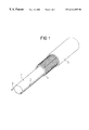
FIG. 1 is a perspective view of a cable with two tear threads in the desired arrangement; and
FIG. 2 is an arrangement of tear threads and auxiliary threads in a woven pattern which is in an unwound condition to illustrate the loop or tying of the threads by the auxiliary threads.
DESCRIPTION OF THE PREFERRED EMBODIMENTS
The principles of the present invention are particularly useful when incorporated in a cable shown in FIG. 1, which has a cable core 1, a cable jacket formed by two layers 4 and 5 and at least two tear threads 2 and 3 which extend between the core 1 and the jacket. In this embodiment, the layer 4 of the cable jacket comprises a steel grooved jacket and the layer 5 is a plastic coating. As shown, the tear threads 2 and 3 should be present in an equidistant fashion with respect to the cable core 1, and this means that they lie diametrically opposite one another.
The tear threads 2 and 3 are wrapped with auxiliary threads, such as 8 and 9 (see FIG. 2), in order to guarantee the positioning shown in FIG. 1 of the two tear threads. FIG. 2 shows a weaving according to the KEMAFIL technology, wherein the tear threads 2 and 3 are components of the weaving. The significantly thinner auxiliary threads 8 and 9 are knitted with the tear threads 2 and 3 so that the tear threads 2 and 3 can no longer move. In the shown embodiment, the auxiliary threads 8 and 9, respectively, form a looping knot, as shown with the reference character 10.
Although the invention was completely and exemplarily described above with reference to the enclosed drawings, someone skilled in the art should recognize that different modifications are possible and are to be included in the scope of the claimed invention. Exemplary different wrappings and looping techniques can be used. In addition, the fabric does not have to be of the KEMAFIL type. Finally, it is also not necessary to integrate the tear threads into the fabric, since it would be sufficient for the fixing at a cable core when the auxiliary thread is arranged over the tear threads as a fixing layer.
Although various minor modifications may be suggested by those versed in the art, it should be understood that we wish to embody within the scope of the patent granted heron all such modifications as reasonably and properly come within the scope of our contribution to the art.

Claims (20)

We claim:
1. A cable with a cable core, a cable jacket and at least one tear thread extending therebetween, the improvement comprising the tear thread being fixed in position by means of at least one auxiliary thread, wherein two tear threads are wrapped by at least one auxiliary thread, and wherein the auxiliary threads are provided as a braid with the two tear threads extending along the longitudinal axis of the cable.
2. A cable with a cable core, a cable jacket and at least one tear thread extending therebetween, the improvement comprising the tear thread being fixed in position by means of at least one auxiliary thread, wherein the at least one auxiliary thread has a lower resistance to tearing than the at least one tear thread.
3. A cable with a cable core, a cable jacket and at least one tear thread extending therebetween, the improvement comprising the tear thread being fixed in position by means of at least one auxiliary thread, wherein the auxiliary threads are provided as a braid or a weave.
4. A cable with a cable core, a cable jacket and at least one tear thread extending therebetween, the improvement comprising the tear thread being fixed in position by means of at least one auxiliary thread, wherein the tear thread is wrapped by said at least one auxiliary thread, and wherein the auxiliary thread is provided as a braid.
5. A method for manufacturing a cable having a cable core, a cable jacket and a tear thread between the core and the jacket, said method comprising the steps of providing a cable core and arranging at least one tear thread on the core, arranging at least one auxiliary thread in order to fix the tear threads in position, and then providing a cable jacket to surround the cable core, the tear thread and the auxiliary thread, wherein the at least one auxiliary thread has a lower resistance to tearing than the at least one tear thread.
6. A method for manufacturing a cable having a cable core, a cable jacket and a tear thread between the core and the jacket, said method comprising the steps of providing a cable core and arranging at least one tear thread on the core, arranging a plurality of auxiliary threads in order to fix the tear threads in position, and then providing a cable jacket to surround the cable core, the tear thread and the auxiliary thread, wherein arranging the at least one tear thread comprises partially wrapping the tear threads with the auxiliary thread including braiding the auxiliary thread and tear thread.
7. A cable comprising a cable core, a cable jacket surrounding the core, means for facilitating stripping of the jacket from the core comprising at least one tear thread located between the core and jacket and means for fixing the position of the tear thread comprising at least one auxiliary thread positioned between the jacket and core and engaging the at least one tear thread, wherein the at least one auxiliary thread has a thickness less than the at least one tear thread.
8. A cable according to claim 2, wherein a plurality of tear threads are provided.
9. A cable according to claim 8, wherein the tear threads are equidistantly arranged around the cable core.
10. A cable according to claim 9, wherein the tear threads are wrapped by one or more auxiliary threads.
11. A cable according to claim 3, wherein the tear threads are part of a braid or weave and extend parallel to the longitudinal axis of the cable.
12. A cable according to claim 2, wherein two tear threads are wrapped by at least one auxiliary thread.
13. A cable according to claim 2, wherein the tear thread is wrapped by said at least one auxiliary thread.
14. A cable according to claim 4, wherein the tear threads are part of the braid and extend parallel to the longitudinal axis of the cable.
15. A method according to claim 5, wherein the step of arranging at least one auxiliary thread arranges a plurality of auxiliary threads.
16. A method according to claim 15, wherein the step of arranging at least one auxiliary thread partially wraps the tear threads with the auxiliary thread.
17. A method according to claim 6, wherein two tear threads and at least two auxiliary threads are knitted around the cable core so that the tear threads extend parallel to the longitudinal axis of the cable and are fixed in position by the auxiliary threads being wrapped therearound.
18. A method according to claim 5, wherein the step of arranging the auxiliary thread partially wraps the tear thread with the auxiliary thread.
19. A method according to claim 5, wherein the step of arranging the tear thread and the auxiliary thread arranges these at the same time and braids the tear thread and auxiliary thread in a woven pattern.
20. A method according to claim 5, wherein the step of arranging tear threads arranges to tear threads and the step of arranging auxiliary threads arranges two auxiliary threads which are knitted together so that the tear threads extend parallel to the longitudinal axis of the cable and are fixed in position by the looping of the auxiliary threads onto the tear threads.
US09/458,472 1998-12-09 1999-12-09 Cable with a cable core, a cable jacket and a tear thread Expired - Lifetime US6314855B1 (en)

Applications Claiming Priority (2)

Application Number Priority Date Filing Date Title
DE19856814A DE19856814A1 (en) 1998-12-09 1998-12-09 Cable with a cable core, a cable jacket and a tear thread
DE19856814 1998-12-09

Publications (1)

Publication Number Publication Date
US6314855B1 true US6314855B1 (en) 2001-11-13

Family

ID=7890518

Family Applications (1)

Application Number Title Priority Date Filing Date
US09/458,472 Expired - Lifetime US6314855B1 (en) 1998-12-09 1999-12-09 Cable with a cable core, a cable jacket and a tear thread

Country Status (3)

Country Link
US (1) US6314855B1 (en)
EP (1) EP1008996A3 (en)
DE (1) DE19856814A1 (en)

Cited By (1)

* Cited by examiner, † Cited by third party
Publication number Priority date Publication date Assignee Title
US20130183177A1 (en) * 2012-01-16 2013-07-18 Schlumberger Technology Corporation Tubing Encased Motor Lead

Families Citing this family (1)

* Cited by examiner, † Cited by third party
Publication number Priority date Publication date Assignee Title
US6813421B2 (en) 2001-12-26 2004-11-02 Corning Cable Systems Llc Fiber optic cable having a ripcord

Citations (17)

* Cited by examiner, † Cited by third party
Publication number Priority date Publication date Assignee Title
US1686098A (en) * 1926-12-14 1928-10-02 Meiwald Franz Insulated flexible conductor and method of producing same
US2087303A (en) * 1934-04-21 1937-07-20 Anaconda Wire & Cable Co Insulated conductor and method of making same
US2450429A (en) * 1944-08-04 1948-10-05 Western Electric Co Electrical cord
US3106815A (en) * 1962-05-07 1963-10-15 Vector Cable Company Apparatus and method for forming stranded cables
US4059951A (en) * 1975-05-05 1977-11-29 Consolidated Products Corporation Composite strain member for use in electromechanical cable
US4299884A (en) * 1979-01-10 1981-11-10 L. Payen & Cie Type of wrapped textile thread and process for its production which involves thermofusion to secure wrapping to core
US4445321A (en) * 1982-11-29 1984-05-01 Hutchinson Raymond E Tendon construction for posttensioning prestressed concrete and the method of making such tendons
US5013127A (en) * 1990-04-26 1991-05-07 Siecor Corporation Flexible fiber optic distribution cable
US5109457A (en) * 1988-12-14 1992-04-28 At&T Bell Laboratories All-dielectric optical fiber cable having enhanced fiber access
WO1992010840A1 (en) 1990-12-13 1992-06-25 Raychem Limited Electrical cable
DE9113530U1 (en) 1991-10-30 1993-02-25 W.L. Gore & Associates Gmbh, 8011 Putzbrunn, De
US5197370A (en) * 1989-06-28 1993-03-30 The Bentley-Harris Manufacturing Company Abrasion resistant braided sleeve
US5642452A (en) * 1995-02-21 1997-06-24 Sumitomo Electric Lightwave Corp. Water-blocked optical fiber communications cable
US5671649A (en) * 1995-02-14 1997-09-30 Bentley-Harris Inc. Method of making protective sleeve with warp spacers
US5744206A (en) * 1994-04-06 1998-04-28 Vitrica, S.A. De C.V. Braided sleeving with rib strands
US5896482A (en) * 1994-12-20 1999-04-20 Lucent Technologies Inc. Optical fiber cable for underwater use using terrestrial optical fiber cable
US6185351B1 (en) * 1999-10-15 2001-02-06 Lucent Technologies, Inc. All-dielectric, self-supporting, loose-tube cable with optical fiber ribbons

Patent Citations (17)

* Cited by examiner, † Cited by third party
Publication number Priority date Publication date Assignee Title
US1686098A (en) * 1926-12-14 1928-10-02 Meiwald Franz Insulated flexible conductor and method of producing same
US2087303A (en) * 1934-04-21 1937-07-20 Anaconda Wire & Cable Co Insulated conductor and method of making same
US2450429A (en) * 1944-08-04 1948-10-05 Western Electric Co Electrical cord
US3106815A (en) * 1962-05-07 1963-10-15 Vector Cable Company Apparatus and method for forming stranded cables
US4059951A (en) * 1975-05-05 1977-11-29 Consolidated Products Corporation Composite strain member for use in electromechanical cable
US4299884A (en) * 1979-01-10 1981-11-10 L. Payen & Cie Type of wrapped textile thread and process for its production which involves thermofusion to secure wrapping to core
US4445321A (en) * 1982-11-29 1984-05-01 Hutchinson Raymond E Tendon construction for posttensioning prestressed concrete and the method of making such tendons
US5109457A (en) * 1988-12-14 1992-04-28 At&T Bell Laboratories All-dielectric optical fiber cable having enhanced fiber access
US5197370A (en) * 1989-06-28 1993-03-30 The Bentley-Harris Manufacturing Company Abrasion resistant braided sleeve
US5013127A (en) * 1990-04-26 1991-05-07 Siecor Corporation Flexible fiber optic distribution cable
WO1992010840A1 (en) 1990-12-13 1992-06-25 Raychem Limited Electrical cable
DE9113530U1 (en) 1991-10-30 1993-02-25 W.L. Gore & Associates Gmbh, 8011 Putzbrunn, De
US5744206A (en) * 1994-04-06 1998-04-28 Vitrica, S.A. De C.V. Braided sleeving with rib strands
US5896482A (en) * 1994-12-20 1999-04-20 Lucent Technologies Inc. Optical fiber cable for underwater use using terrestrial optical fiber cable
US5671649A (en) * 1995-02-14 1997-09-30 Bentley-Harris Inc. Method of making protective sleeve with warp spacers
US5642452A (en) * 1995-02-21 1997-06-24 Sumitomo Electric Lightwave Corp. Water-blocked optical fiber communications cable
US6185351B1 (en) * 1999-10-15 2001-02-06 Lucent Technologies, Inc. All-dielectric, self-supporting, loose-tube cable with optical fiber ribbons

Cited By (1)

* Cited by examiner, † Cited by third party
Publication number Priority date Publication date Assignee Title
US20130183177A1 (en) * 2012-01-16 2013-07-18 Schlumberger Technology Corporation Tubing Encased Motor Lead

Also Published As

Publication number Publication date
EP1008996A2 (en) 2000-06-14
DE19856814A1 (en) 2000-06-15
EP1008996A3 (en) 2000-12-06

Similar Documents

Publication Publication Date Title
US7235737B2 (en) Electromagnetic shielding sleeve which is intended, for example, to protect bundles of cables for use in aeronautics
US10202714B2 (en) Braided textile sleeve with self-sustaining expanded and contracted states and method of construction thereof
JP5874384B2 (en) cable
CN210119616U (en) Rat-proof optical cable
JP2008235024A (en) Flat cable
US10415162B2 (en) Impact resistant, shrinkable knitted tubular sleeve and method of construction thereof
US5414212A (en) Shielded "herringbone" harness
EP3533122B1 (en) Multi-cavity, shrinkable sleeve and method of construction thereof
JP2003060386A (en) Electromagnetic wave shielding coating material
US6314855B1 (en) Cable with a cable core, a cable jacket and a tear thread
JP2018137197A (en) Wire harness with braid cover and manufacturing method thereof
US10711378B2 (en) Knit textile sleeve with self-sustaining expanded and contracted states and method of construction thereof
US20200013523A1 (en) Composite Cable
US5303630A (en) Double serve braiding for jacketed cable
US20040144559A1 (en) Flexible braided electrical cable bundle
JP2002116357A (en) Flexible optical fiber cable
WO2017204003A1 (en) Protective member and electric wire with protective member
JP2007257975A (en) Complex cable
EP0826805A3 (en) Comingled composite yarn and method for forming same
JPH10223054A (en) Moving cable
US20180233257A1 (en) Wire harness protection structure and method for producing braided cover-equipped wire harness
JP7254265B2 (en) Cable for signal transmission equipment and method for manufacturing cable for signal transmission equipment
JP2000346250A (en) Pressureproof hose
JP2017212818A (en) Wire protection member, wire with wire protection member, and method of manufacturing wire with wire protection member
US1661102A (en) Ended cord and method of producing the same

Legal Events

Date Code Title Description
AS Assignment

Owner name: SIEMENS AKTIENGESELLSCHAFT, GERMANY

Free format text: ASSIGNMENT OF ASSIGNORS INTEREST;ASSIGNORS:UHLENHUTH, GUENTHER;BUECHNER, OLIVER;REEL/FRAME:010687/0131

Effective date: 19991220

STCF Information on status: patent grant

Free format text: PATENTED CASE

AS Assignment

Owner name: CCS TECHNOLOGY, INC., DELAWARE

Free format text: ASSIGNMENT OF ASSIGNORS INTEREST;ASSIGNOR:SIEMENS AKTIENGESELLSCHAFT;REEL/FRAME:013362/0204

Effective date: 20000131

FPAY Fee payment

Year of fee payment: 4

FPAY Fee payment

Year of fee payment: 8

FPAY Fee payment

Year of fee payment: 12