US6318156B1 - Multiphase flow measurement system - Google Patents
Multiphase flow measurement system Download PDFInfo
- Publication number
- US6318156B1 US6318156B1 US09/428,416 US42841699A US6318156B1 US 6318156 B1 US6318156 B1 US 6318156B1 US 42841699 A US42841699 A US 42841699A US 6318156 B1 US6318156 B1 US 6318156B1
- Authority
- US
- United States
- Prior art keywords
- density
- gas
- majority
- measuring
- liquid
- Prior art date
- Legal status (The legal status is an assumption and is not a legal conclusion. Google has not performed a legal analysis and makes no representation as to the accuracy of the status listed.)
- Expired - Lifetime
Links
- 238000005259 measurement Methods 0.000 title claims abstract description 89
- XLYOFNOQVPJJNP-UHFFFAOYSA-N water Substances O XLYOFNOQVPJJNP-UHFFFAOYSA-N 0.000 claims abstract description 99
- 238000000034 method Methods 0.000 claims abstract description 27
- 239000007788 liquid Substances 0.000 claims description 107
- 239000012071 phase Substances 0.000 claims description 62
- 239000012530 fluid Substances 0.000 claims description 40
- 239000007791 liquid phase Substances 0.000 claims description 33
- 239000011800 void material Substances 0.000 claims description 31
- 238000004364 calculation method Methods 0.000 claims description 25
- 238000012360 testing method Methods 0.000 abstract description 25
- 230000008569 process Effects 0.000 abstract description 5
- 239000007789 gas Substances 0.000 description 131
- 239000003921 oil Substances 0.000 description 70
- 238000004519 manufacturing process Methods 0.000 description 39
- 239000000203 mixture Substances 0.000 description 30
- 238000001739 density measurement Methods 0.000 description 16
- 238000000926 separation method Methods 0.000 description 14
- 230000005484 gravity Effects 0.000 description 10
- 230000006870 function Effects 0.000 description 7
- 230000000694 effects Effects 0.000 description 6
- 239000000523 sample Substances 0.000 description 5
- 238000005204 segregation Methods 0.000 description 5
- 239000000463 material Substances 0.000 description 4
- VNWKTOKETHGBQD-UHFFFAOYSA-N methane Chemical compound C VNWKTOKETHGBQD-UHFFFAOYSA-N 0.000 description 4
- 239000003208 petroleum Substances 0.000 description 4
- 230000004044 response Effects 0.000 description 4
- 238000004458 analytical method Methods 0.000 description 3
- 238000013016 damping Methods 0.000 description 3
- 238000010586 diagram Methods 0.000 description 3
- 230000002706 hydrostatic effect Effects 0.000 description 3
- 238000009434 installation Methods 0.000 description 3
- 238000011545 laboratory measurement Methods 0.000 description 3
- 239000003129 oil well Substances 0.000 description 3
- 230000001052 transient effect Effects 0.000 description 3
- 238000010521 absorption reaction Methods 0.000 description 2
- 239000012223 aqueous fraction Substances 0.000 description 2
- 230000000712 assembly Effects 0.000 description 2
- 238000000429 assembly Methods 0.000 description 2
- 238000012937 correction Methods 0.000 description 2
- 239000010779 crude oil Substances 0.000 description 2
- 238000013461 design Methods 0.000 description 2
- 238000001514 detection method Methods 0.000 description 2
- 238000007599 discharging Methods 0.000 description 2
- 230000033001 locomotion Effects 0.000 description 2
- 239000003345 natural gas Substances 0.000 description 2
- 238000005025 nuclear technology Methods 0.000 description 2
- 230000009467 reduction Effects 0.000 description 2
- 230000008054 signal transmission Effects 0.000 description 2
- 239000004215 Carbon black (E152) Substances 0.000 description 1
- 230000009471 action Effects 0.000 description 1
- 230000001154 acute effect Effects 0.000 description 1
- 230000005540 biological transmission Effects 0.000 description 1
- 238000012769 bulk production Methods 0.000 description 1
- 230000008859 change Effects 0.000 description 1
- 238000009833 condensation Methods 0.000 description 1
- 230000005494 condensation Effects 0.000 description 1
- 230000001186 cumulative effect Effects 0.000 description 1
- 230000007423 decrease Effects 0.000 description 1
- 238000011161 development Methods 0.000 description 1
- 238000005516 engineering process Methods 0.000 description 1
- 229930195733 hydrocarbon Natural products 0.000 description 1
- 150000002430 hydrocarbons Chemical class 0.000 description 1
- 238000002955 isolation Methods 0.000 description 1
- 238000007726 management method Methods 0.000 description 1
- 230000007246 mechanism Effects 0.000 description 1
- 239000003595 mist Substances 0.000 description 1
- 238000012986 modification Methods 0.000 description 1
- 230000004048 modification Effects 0.000 description 1
- 238000012806 monitoring device Methods 0.000 description 1
- 230000010355 oscillation Effects 0.000 description 1
- 230000000737 periodic effect Effects 0.000 description 1
- 238000005191 phase separation Methods 0.000 description 1
- 230000005855 radiation Effects 0.000 description 1
- 150000003839 salts Chemical class 0.000 description 1
- 238000005070 sampling Methods 0.000 description 1
- 230000035945 sensitivity Effects 0.000 description 1
- 238000001228 spectrum Methods 0.000 description 1
- 230000003068 static effect Effects 0.000 description 1
- 238000003860 storage Methods 0.000 description 1
Images


Classifications
-
- E—FIXED CONSTRUCTIONS
- E21—EARTH DRILLING; MINING
- E21B—EARTH DRILLING, e.g. DEEP DRILLING; OBTAINING OIL, GAS, WATER, SOLUBLE OR MELTABLE MATERIALS OR A SLURRY OF MINERALS FROM WELLS
- E21B49/00—Testing the nature of borehole walls; Formation testing; Methods or apparatus for obtaining samples of soil or well fluids, specially adapted to earth drilling or wells
- E21B49/08—Obtaining fluid samples or testing fluids, in boreholes or wells
- E21B49/087—Well testing, e.g. testing for reservoir productivity or formation parameters
- E21B49/0875—Well testing, e.g. testing for reservoir productivity or formation parameters determining specific fluid parameters
-
- G—PHYSICS
- G01—MEASURING; TESTING
- G01F—MEASURING VOLUME, VOLUME FLOW, MASS FLOW OR LIQUID LEVEL; METERING BY VOLUME
- G01F1/00—Measuring the volume flow or mass flow of fluid or fluent solid material wherein the fluid passes through a meter in a continuous flow
- G01F1/74—Devices for measuring flow of a fluid or flow of a fluent solid material in suspension in another fluid
-
- G—PHYSICS
- G01—MEASURING; TESTING
- G01F—MEASURING VOLUME, VOLUME FLOW, MASS FLOW OR LIQUID LEVEL; METERING BY VOLUME
- G01F1/00—Measuring the volume flow or mass flow of fluid or fluent solid material wherein the fluid passes through a meter in a continuous flow
- G01F1/76—Devices for measuring mass flow of a fluid or a fluent solid material
- G01F1/78—Direct mass flowmeters
- G01F1/80—Direct mass flowmeters operating by measuring pressure, force, momentum, or frequency of a fluid flow to which a rotational movement has been imparted
- G01F1/84—Coriolis or gyroscopic mass flowmeters
-
- G—PHYSICS
- G01—MEASURING; TESTING
- G01F—MEASURING VOLUME, VOLUME FLOW, MASS FLOW OR LIQUID LEVEL; METERING BY VOLUME
- G01F15/00—Details of, or accessories for, apparatus of groups G01F1/00 - G01F13/00 insofar as such details or appliances are not adapted to particular types of such apparatus
- G01F15/08—Air or gas separators in combination with liquid meters; Liquid separators in combination with gas-meters
-
- G—PHYSICS
- G01—MEASURING; TESTING
- G01N—INVESTIGATING OR ANALYSING MATERIALS BY DETERMINING THEIR CHEMICAL OR PHYSICAL PROPERTIES
- G01N9/00—Investigating density or specific gravity of materials; Analysing materials by determining density or specific gravity
- G01N9/002—Investigating density or specific gravity of materials; Analysing materials by determining density or specific gravity using variation of the resonant frequency of an element vibrating in contact with the material submitted to analysis
Definitions
- the present invention pertains to the field of flow metering technology including systems for use in measuring production volumes including a multiphase mixture of discrete phases, e.g., a mixture including oil, gas, and water phases. More specifically, the separator system utilizes a Coriolis flowmeter in combination with a two phase separator to measure production volumes of the respective components or phases of the multiphase mixture.
- phase refers to a type of fluid that may exist in contact with other fluids, e.g., a mixture of oil and water includes a discrete oil phase and a discrete water phase.
- a mixture of oil, gas, and water includes a discrete gas phase and a discrete liquid phase with the liquid phase including an oil phase and a water phase.
- fluid is used herein in the context that fluid includes gas and liquids.
- Older pressure vessel separators are bulky and occupy a relatively large surface area. This surface area is very limited and quite expensive to provide in certain installations including offshore production platforms and subsea completion templates. Some development efforts have attempted to provide multiphase measurement capabilities in compact packages for use in locations where surface area is limited. These packages typically require the use of nuclear technology to obtain multiphase flow measurements.
- Coriolis flowmeters are mass flowmeters that can also be operated as vibrating tube densitometers.
- the density of each phase may be used to convert the mass flow rate for a particular phase into a volumetric measurement. Numerous difficulties exist in using a Coriolis flowmeter to identify the respective mass percentages of oil, gas, and water in a total combined flow stream.
- U.S. Pat. No. 5,029,482 teaches the use of empirically-derived correlations that are obtained by flowing combined gas and liquid flow streams having known mass percentages of the respective gas and liquid components through a Coriolis meter. The empirically-derived correlations are then used to calculate the percentage of gas and the percentage of liquid in a combined gas and liquid flow stream of unknown gas and liquid percentages based upon a direct Coriolis measurement of the total mass flow rate.
- the composition of the fluid mixture from the well can change with time based upon pressure, volume, and temperature phenomena as pressure in the reservoir depletes and, consequently, there is a continuing need to reverify the density value.
- U.S. Pat. No. 4,773,257 teaches that a water fraction of a total oil and water flow stream may be calculated by adjusting the measured total mass flow rate for water content, and that the corresponding mass flow rates of the respective oil and water phases may be converted into volumetric values by dividing the mass flow rate for the respective phases by the density of the respective phases.
- the density of the respective phases must be determined from actual laboratory measurements.
- the '257 patent relies upon separation equipment to accomplish separation of gas from the total liquids, and this separation is assumed to be complete.
- U.S. Pat. No. 5,654,502 describes a self-calibrating Coriolis flowmeter that uses a separator to obtain respective oil and water density measurements, as opposed to laboratory density measurements.
- the oil density measurements are corrected for water content, which is measured by a water cut monitor or probe.
- the '502 patent relies upon a separator to eliminate gas from the fluids traveling through the meter, and does not teach a mechanism for providing multiphase flow measurements when gas is part of the flow stream that is applied to the Coriolis flowmeter.
- Water cut probes are used to measure water content in the segregated oil phase because a residual water content of up to about ten percent typically remains in the visibly segregated oil component.
- the term ‘water cut’ is used to describe the water content of a multiphase mixture, and is most often applied to a ratio that represents a relationship between a volume of oil and a volume of water in an oil and water mixture. According to the most conventional usage of the term ‘water-cut’, well production fluids would have a 95% water-cut when water comprises 95 out of a total 100 barrels of oil and water liquids.
- water-cut is sometimes also used to indicate a ratio of the total volume of oil produced to the total volume of water produced.
- oil-cut could imply the oil volume divided by the combined oil and water volume.
- water-cut encompasses any value that is mathematically equivalent to a value representing water or oil as a percentage of a total liquid mixture including water and oil.
- the present invention overcomes the problems that are outlined above by providing a fully automated Coriolis-based well test system which does not require manual sampling or laboratory analysis of the production fluids in order to determine the density of the oil and gas components. Additionally, the test system eliminates volumetric measurement errors that derive from the liberation of solution gas at reduced pressures.
- the well test system of the invention has two modes of operation.
- the test system operates as a normal well test system to measure the volume of respective components that are separated from a component mixture, namely, a wellhead production material including oil, gas, and water components.
- the well test system also has a special density determination mode that avoids the need to obtain hand samples of the production fluids for density measurements.
- The-on-site density measurements obtained from the system are more accurate than laboratory measurements because the fluids are measured at line conditions.
- the system also includes devices that separate a combined flowstream including multiphase wellhead production fluids into separate components.
- a valve manifold is used to selectively fill a vortex separator with the production of a single well.
- a gravity separator is used to retain a mixture of oil, gas, and water phases or components from multiple wells while the forces of gravity segregate these components from the production mixture.
- a dump valve is opened to at least partially drain the liquid components of the production component mixture from the gravity separator after separation of the respective components.
- Coriolis flowmeters may be operated in a mass flowmeter mode and densitometer mode. These meters are used to measure the mass flow rates of the respective oil and water components as they leave the respective separators. Density measurements are used obtained from the segregated oil components of multiphase flow. A water-cut monitor is used to obtain water-cut readings of the segregated oil phase. Altogether, fluid density, temperature, mass flow rate, and water-cut measurements are used to calculate a volumetric flow rate for the oil and water components in the production stream. This correction results in a more accurate calculation for the volumetric oil flow rate.
- volumetric test errors are also minimized by connecting a pressurized gas source to the test separator.
- the pressurized gas source is used to maintain a substantially constant separator pressure even when the separator dump valve is permitting flow of liquids from within the test separator.
- FIG. 1 depicts a schematic layout of an automated well test system according to the present invention
- FIGS. 2A and 2B depict a flow chart diagram governing the operation of the FIG. 1 system
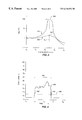
- FIG. 3 is a plot of hypothetical data demonstrating the practical effects of gas damping on the frequency response of flowtubes in a Coriolis flowmeter.
- FIG. 1 depicts a schematic diagram of a compact multiphase flow measurement system 100 for use in the petroleum industry
- System 100 includes an incoming multiphase flow line 102 that discharges into a vertical two phase vortex separator 104 .
- the vortex separator 104 discharges gas into an upper gas measurement flow line 106 and discharges liquids into a lower liquid measurement flow line 108 .
- the gas measurement flow line 106 and the liquid measurement flow line 108 recombine into discharge line 110 after flow measurements have been performed.
- a controller 112 includes a central processor together with associated circuitry for operating the respective components of system 100 .
- the system 100 is mounted on skid structure 114 for portability, and a production manifold 116 supplies multiphase fluids to system 100 from a plurality of oil or gas wells.
- Discharge flow line 110 leads to a three phase production separator 118 for separation of gas, water and oil phases prior to a point of commercial sale.
- the incoming multiphase flow line 102 receives multiphase fluids including oil, gas, and water from production manifold 116 along the direction of arrow 120 .
- a venturi section 122 utilizes the well known Bernouli effect to reduce pressure in the incoming multiphase fluids within flow line 102 at the throat of the venturi. It is preferred that the degree of pressure reduction occurs to a level which approximates the internal working pressure within the liquid Coriolis meter 166 . This reduction in pressure liberates or flashes gas from the multiphase fluids within flow line 102 .
- An incline/decline section 124 facilitates gravity segregation in the gas and liquid phases of the multiphase fluids preceding the vortex separator 104 .
- a horizontal discharge element 126 feeds the vortex separator 104 .
- Vortex separator 104 is depicted in midsectional view to reveal interior working components.
- Discharge element 126 is operably positioned for tangential discharge into the cylindrical interior separation section of vortex separator 104 . This manner of discharge causes a tornado or cyclone effect to occur in a liquid portion 128 of multiphase fluids within vortex separator 104 .
- the liquid portion 128 is a majority liquid phase including discrete water, oil, and entrained gas phases. Centrifugal forces arising from the cyclone effect cause additional separation of the entrained gas phase from the liquid portion 128 , but it is not possible to completely eliminate the entrained gas phase except at relatively low flow rates permitting additional gravity segregation of the entrained gas phase.
- the liquid portion 128 discharges from vortex separator 104 into the liquid measurement flow line 108 .
- a water trap 130 is installed in the lower portion of vortex separator 104 . This trap may be bled to obtain periodic water density measurements, or a water density meter (not depicted in FIG. 1) may be installed in combination with the trap 130 to provide water density information to controller 112 .
- a gas portion 132 of the multiphase fluids within vortex separator is a majority gas phase including gas together with mists of oil and water.
- a mist collecting screen 134 is used for partial condensation of the mists, which in condensed form drip back into the liquid portion 128 .
- Gas portion 132 discharges into the gas measurement flow line 106 .
- Gas measurement flow line 106 includes a pressure transmitter 135 that transmits an absolute pressure reading of pressure within gas measurement flow line 106 to controller 112 on electrical line 136 .
- Pressure transmitter 135 may be purchased commercially, for example, as a Model 2088 pressure transmitter from Rosemount of Eden Prairie, Minn.
- a tube 138 connects gas measurement line 136 with the bottom of vortex separator 104 .
- Tube 138 contains a hydrostatic gauge 140 coupled with a pressure transmitter 142 for use in transmitting pressure information concerning the hydrostatic head between point 144 within gas measurement flow line 106 and point 146 at the bottom of vortex separator 104 .
- Electrical line 148 connects the pressure transmitter 142 with controller 112 , which uses the hydrostatic head data from pressure transmitter 142 to open and close electrically operable throttling valves 150 and 174 for pressure adjustment assuring proper operation of vortex separator 104 , i.e., to prevent vortex separator from becoming overfull with gas to the point where gas portion 132 discharges into liquid measurement flow line 108 or to the point where liquid portion 128 discharges into gas measurement flow line 106 .
- Electrical lines 152 and 176 operably connect controller 112 with the throttling valves 150 and 174 , which may, for example, be purchased as Model V2001066-ASCO valves from Fisher of Marshall Town, Iowa.
- a Coriolis mass flowmeter 154 in gas measurement flow line 106 provides mass flow rate and density measurements on the gas portion 132 of multiphase fluids within gas measurement flow line 106 .
- the Coriolis mass flowmeter 154 is coupled with a flow transmitter 156 for providing signals representing these measurements to controller 112 .
- Coriolis flowmeter 154 is electronically configured for operations including measurements of mass flow rates, densities, and temperatures of materials passing through gas measurement flow line 106 .
- Exemplary forms of Coriolis flowmeter 154 include the ELITE Models CMF300356NU and Model CMF300H551NU, which are available from Micro Motion of Boulder, Colo.
- Electrical line 158 operably couples flow transmitter 156 with controller 112 for transmission of these signals.
- a check valve 160 in gas measurement flow line 106 assures positive flow in the direction of arrow 162 , thus preventing intrusion of liquid portion 128 into gas measurement flow line 106 .
- Liquid measurement flow line 108 contains a static mixer 164 , which turbulates the liquid portion 128 within liquid measurement flow line 108 to prevent gravity segregation of the respective oil, water, and entrained gas phases.
- a Coriolis flowmeter 166 provides mass flow rate and density measurements of liquid portion 128 within liquid measurement flow line 108 , and is connected to flow transmitter 168 for transmission of signals representing these measurements on electrical line 170 to controller 112 .
- a water cut monitor 172 is installed in liquid measurement flow line 108 to measure the water cut in liquid portion 128 within liquid measurement flow line 108 .
- the type of water-cut monitor is selected depending upon how large the water-cut is expected to be in the flow stream. For example, capacitance meters are relatively inexpensive, but other types of meters may be required where the water-cut may exceed about 30% by volume.
- Capacitance or resistance probes operate on the principle that oil and water have drastically different dielectric constants. These probes lose sensitivity with increasing water content, and provide acceptably accurate water-cut measurements only where the water volume is less than about 20% to 30% of the total flow stream. The upper 30% accuracy limit is far below the level that is observed from many producing wells. For example, the total liquid production volume of an oil well can be 99% water. Capacitance or resistivity based water-cut monitors, therefore, are relegated to determining the water-cut in an oil component that has a relatively low water content.
- a water-cut probe can measure the volumetric percentage of water in a combined oil and water flow stream.
- Water cut monitoring devices including microwave devices are capable of detecting water in an amount up to about one hundred percent of the flow mixture, but in environments including three phase flow are subject to interpreting gas content as oil. This interpretation occurs because microwave detection devices operate on the principle that water in the spectrum of interest absorbs sixty times more microwave energy than does crude oil. The absorption calculations assume that no natural gas is present, but natural gas absorbs twice as much microwave radiation than does crude oil. It follows that a microwave water cut detection system could correct the water cut reading by compensating for the fact that gas in the mixture has affected the measurement.
- Electrical line 173 operably connects water cut monitor 172 with controller 112 .
- Controller 112 uses an electrically actuated two-way valve 174 to control pressure in liquid measurement line 108 in a manner that assures proper operation of vortex separator 104 in cooperation with valve 150 , i.e., valve 174 is opened and closed to prevent gas portion 132 from discharging into liquid measurement flow line 108 and to prevent liquid portion 128 from discharging into gas measurement flow line 106 .
- Electrical line 176 operably connects valve 174 with controller 112 .
- a check valve 178 in liquid measurement flow line 108 assures positive flow in the direction of arrow 180 , thus preventing intrusion of gas portion 132 into the liquid measurement flow line 108 .
- the gas measurement flow line 106 meets in a T with liquid measurement flow line 108 to form a common discharge flow line 110 leading to production separator 118 .
- Controller 112 is an automation system that is used to govern the operation of system 100 .
- controller 100 includes a computer that is programmed with data acquisition and programming software together with driver circuitry and interfaces for operation of remote devices.
- a preferred form of controller 112 is the Fisher Model ROC364.
- the production manifold 116 contains a plurality of electronically operable three way valves, e.g., valves 182 and 184 , which each have corresponding production sources, such as an oil well 186 or a gas well 188 .
- a particularly preferred three-way valve for use in this application is the Xomox TUFFLINE 037AX WCB/316 well switching valve with a MATRYX MX200 actuator.
- the valves are preferably configured to each receive production fluids from a corresponding individual well, but may also receive production from a group of wells. Controller 112 selectively configures these valves by transmitting signals on electrical line 190 .
- the valves are selectively configured to flow multiphase fluids from a well 186 or combinations of wells (e.g. wells 186 and 188 ) into rail 192 for delivery of fluids into incoming multiphase flow line 102 while other valves are selectively configured to bypass system 100 by flowing through bypass flow line 194 .
- Production separator 118 is connected to pressure transmitter 195 and an electrical line 196 for transmission of signals to controller 112 .
- Separator 118 is operably connected with a gas sales line, an oil sales line, and a salt water discharge line (not depicted in FIG. 1) in any conventional manner known to those skilled in the art.
- FIGS. 2A and 2B depict a schematic process diagram of a process P 200 representing control logic for use in programming controller 112 .
- These instructions typically reside in an electronic memory or an electronic storage device for access and use by controller 112 . Instructions that embody the process P 200 can be storied on any machine readable medium for retrieval, interpretation and execution by controller 112 or similar devices that are connected to system 100 in any operable manner.
- Process P 200 begins with step P 202 in which controller 112 determines that it is proper to enter a production test mode. With regard to FIG. 1, this means that controller 112 selectively configures the valves 182 and 184 of production manifold 116 to flow a well or an operator-selected combinations of wells corresponding to production sources 186 and 188 through rail 192 and into incoming multiphase flow line 102 . This determination is usually performed on the basis of a time delay, e.g., to test each well at least once per week.
- the test mode may also be performed on a continuous basis with the respective valves of production manifold 116 always being selectively configured to flow into system 100 while other valves are configured to bypass system 100 through bypass line 194 .
- These types of well test measurements are conventionally used in allocating, on a deliverability basis, the percentages of the total flow stream that pass through production separator 118 to specific production sources, e.g., sources 186 and 188 .
- Manually actuated valves 196 and 197 can be opened and closed for selective isolation of system 100 , i.e., valves 196 and 197 can both be closed for the removal of all components that are mounted on skid 114 .
- An electrically actuated valve 199 is normally closed.
- a second or redundant bypass line 198 interior to valves 196 and 197 permits flow to bypass system 100 when valve 199 is open and valves 150 and 174 are closed.
- step P 204 controller 112 constricting or opening valves 150 and 174 to reduce or increase the total flow rate through vortex separator 104 for the purpose of separating gas from liquid phases in the multiphase fluid.
- the total flow rate through system 100 need not be reduced because controller 112 can open valve 199 to permit flow through interior bypass 198 .
- the exact flow rate depends upon the physical volume of the vortex separator and liquid measurement flow line 108 , as well as the amount of fluid that sources 186 and 188 are capable of delivering to system 100 .
- the object of reducing the flow rate through system 100 is to eliminate entrained bubbles from liquid measurement flow line 108 through the use of vortex separator 104 with assistance by gravity segregation while the flow rate is still high enough to prevent substantial gravity segregation of oil from water in the remaining liquid phase. It is also possible to accomplish substantially complete separation of the gas phase from the liquid phase by increasing the flow rate with separation being accomplished by centrifugal forces through vortex separator 104 . Controller 112 monitors the drive gain or pickoff voltage from Coriolis flowmeter 166 for this purpose, as explained with reference to FIGS. 3 and 4.
- FIG. 3 is a plot of hypothetical data demonstrating the practical effects of gas damping on the frequency response of flowtubes in the Coriolis flowmeter 166 (see also FIG. 1 ).
- the log of transmissivity is plotted as a function of the frequency of alternating voltage applied to the drive coil of Coriolis flowmeter 166 , e.g., at frequencies f 0 , f 1 , and f 2 .
- a first curve 300 corresponds to the undamped system of Equation (1), i.e., no gas is present in the fluid being measured.
- a second curve 302 corresponds to a damped system where gas is present. Both curves 300 and 302 have an optimal value 304 and 304 ′, respectively, at the natural frequency f n .
- FIG. 4 is a plot of hypothetical data showing the relationship between drive gain and time for an event 400 where a transient bubble enters the Coriolis flowmeter 166 as a bubble entrained in a multiphase fluid.
- the bubble enters at time 402 and exits at time 404 .
- Drive gain is expressed as a percentage in FIG. 4, and plotted as a function of time at intervals, e.g., t 1 , t 2 , and t 3 .
- Controller 112 (see also FIG. 1) is programmed to monitor drive gain or transmissivity by comparing the same against a threshold value 406 . Where the drive gain or transmissivity of curve 408 exceeds threshold 406 , controller 112 recognizes that density measurements are affected by the presence of transient bubbles.
- Coriolis flowmeter 166 uses only density values obtained when drive gain is less than threshold 406 for purposes of step P 206 .
- the exact level of threshold 406 depends upon the specific meter design together with the intended environment of use, and is intended to permit less than one to two percent gas by volume in the multiphase fluid.
- the pickoff voltage drops in inverse proportion to the event 400 of the curve 408 shown in FIG. 4 .
- the meters are sometimes programmed to sense this drop in amplitude, and they respond by vibrating an oscillation coil to an amplitude of maximum design specification until the gas damping effect is reversed.
- step P 206 includes Coriolis flowmeter 166 measuring density of the liquid phase without entrained gas.
- This density measurement is intended to represent density of the liquid phase having no gas voids.
- This density measurement is referred to as ⁇ L in the discussion below, and is used to describe the density of a liquid mixture including gas and oil with no entrained gas fraction.
- ⁇ L in the discussion below, and is used to describe the density of a liquid mixture including gas and oil with no entrained gas fraction.
- step P 208 controller 112 selectively adjusts valves 150 and 174 in a manner that optimizes separation results in vortex separator 104 according to manufacturer's specifications based upon the gross rates of flow through Coriolis flowmeters 154 and 166 together with pressure signals received from pressure transmitter 135 and differential pressure gauge 140 .
- production manifold 116 is configured to flow for active producing well test measurements.
- Vortex separator 104 functions differently in this step, as compared to step P 204 , because controller 112 does not adjust valves 150 and 174 in a manner that reduces drive gain below the threshold 406 shown in FIG. 4 . In this circumstance, the majority liquid phase flowing through liquid measurement line 108 may include entrained gas bubbles.
- Step P 210 includes the use of Coriolis flowmeter 166 to measure the total mass flow rate Q TL of the majority liquid phase including entrained gas within liquid measurement line 108 , as well as the density of the majority liquid phase. This density measurement is referred to as ⁇ meas in the discussion that follows.
- controller 112 determines the dry gas density ⁇ gas of the gas in the multiphase fluid.
- Gas density may be calculated from pressure and temperature information using well known correlations developed by the American Gas Association based upon gas gravity, or laboratory analysis may provide other empirical correlations for gas density determined from actual measurements of produced gas from the multiphase flow stream.
- Another alternative technique for the determination of gas density is to obtain an actual density measurement from Coriolis flowmeter 154 simultaneously with step P 204 or in a separate step P 210 where controller 112 selectively adjusts valves 150 and 174 to minimize the drive gain intensity shown in FIG. 4 .
- Equation (2) will be used in an iterative convergence algorithm.
- a first guess e.g., a stored value for ⁇ calc from the preceding cycle of test measurements for a particular production source 186 or an arbitrary value such as 0.8 g/cc.
- a particularly preferred manner of providing a first guess for the value of ⁇ calc is to obtain a water cut measurement from water cut monitor 172 . Then, it is possible to assume that no gas is present in the multiphase flow mixture and solve Equation (3) for ⁇ calc :
- WC water cut expressed as a fraction comprising the amount of water in the liquid mixture divided by the total volume of the liquid mixture
- ⁇ w is the density of water in the liquid mixture
- ⁇ o is the density of oil in the liquid mixture.
- the resultant first guess for ⁇ calc is the theoretical value of a liquid mixture having no gas void fraction.
- the measured density ⁇ meas will be less than ⁇ calc when x i is greater than zero, provided the values ⁇ w and ⁇ o are correct.
- the values ⁇ w and ⁇ o may be obtained from laboratory measurements that are performed on samples of the majority liquid phase including respective oil and water phases. For example, a water density value may be obtained from a hydrometer connected to water trap 130 . These values may also be approximated to acceptable levels of accuracy by well known empirical correlations that are published by the American Petroleum Institute.
- step P 216 controller 112 performs a calculation to determine whether the last guess for ⁇ calc has provided a calculation of X Li according to Equation (2) wherein the value of X i has converged within an acceptable range of error.
- the next guess for ⁇ calc is calculated as:
- ⁇ calci ( ⁇ gas X Li )+(1 ⁇ X Li ) ⁇ L (4)
- ⁇ calci is the next guess for ⁇ calc calculated using the value X Li from Equation (2)
- ⁇ L is the density of the liquid mixture
- D is the absolute value of a delimiter representing a negligible error, e.g., 0.01 g/cc, or approximating the limits of precision that is available from Coriolis flowmeter 166
- ⁇ calci is the present value calculated according to Equation (4)
- ⁇ calci-1 is the old value of ⁇ calci from the prior iteration of Equation (2) that produced the X Li value corresponding to ⁇ calci .
- water cut meter 172 is somewhat redundant if there is no gas phase in the multiphase flow, and may then be optionally eliminated because it is not a required value for this iterative convergence technique.
- step P 214 A a more rigorous or noniterative solution is available, provided that the measured water cut value supplied by water cut meter 172 is within a range where the meter functions with acceptable accuracy and precision.
- the meter reading is a function of the fluid content, and this permits the simultaneous solution of a system of three equations to provide answers for three variables where the equations are:
- ⁇ w is the density of water in the flow stream
- ⁇ o is the density of oil in the flow stream
- ⁇ g is the density of gas in the flow stream
- ⁇ mix is the density of the combined flow stream
- q w is the fractional flow rate of water by volume (i.e., a water-cut)
- q 0 is the fractional flow rate of oil by volume
- q g is the fractional flow rate of gas by volume
- f(sat) is a function of flow stream content that is unique to a particular type of water-cut meter providing a total meter reading M.
- step P 222 entails using Coriolis flowmeter 154 to measure the mass flow rate Q TG and density ⁇ mgas of the majority gas phase flowing through Coriolis flowmeter 154 under the flow conditions of step P 208 .
- XG is a fraction corresponding to a volume of gas taken with respect to the total volume of the majority gas phase
- ⁇ mgas is a value obtained in step P 222
- ⁇ gas is a value obtained in step P 212
- ⁇ L is a value obtained in step P 206 .
- step P 224 the value of water cut obtained from water cut monitor 172 is adjusted, as needed, to compensate for the presence of gas in the majority liquid phase.
- the gas void fraction X Li is known, it is possible to use this value to correct water cut readings for microwave absorption based upon the assumption that only oil and water are present.
- Step P 226 includes using the data thus acquired to solve for the flow rates of the three respective phases in each of the majority liquid phase and the majority gas phase. These equations are useful for this purpose:
- V L Q L ⁇ L ;
- V O Q O ⁇ o ;
- V G Q G P gas ; and
- V W Q W P W , ( 22 )
- Q L is the total mass flow rate of the liquid phases flowing through system 100 ;
- Q TL is the total mass flow rate of the majority liquid phase including entrained gas;
- X i is the gas void fraction in the majority liquid phase determined from step P 214 and resulting in convergence in step P 218 ;
- Q TG is the total gas mass flow rate of the majority gas phase measured in step P 222 ;
- X G is the gas void fraction in the majority gas phase determined in step P 224 ;
- Q G is the total gas mass flow rate through system 100 ;
- ⁇ O is the total oil mass flow rate through system 100 ;
- Q W is the total water mass flow rate through system 100 ;
- WC is the water cut provided from water cut monitor 172 with corrections as needed in step P 224 ;
- V L is the total volumetric flow rate of the liquid phases flowing through system 100 ;
- ⁇ L is the liquid phase density determined in step P 206 ;
- V O is the total oil volumetric flow rate through system 100
- step P 232 controller 112 determines if a new test configuration should be executed. If controller 112 determines that a new test configuration should be executed, then controller 112 returns to step P 204 . If controller 112 determines that a new test configuration should not be executed, then controller 112 exits the production test mode in step P 234 .
- Controller 112 in step P 230 interacts with system components including production manifold 116 to optimize field efficiency. For example, in an oilfield having drive energy that is predominated by a gas cap, production efficiency is optimized when the gas cap is depleted after the oil is recovered. It is desirable to produce oil referentially before the gas, and the gas-oil contact may move downward into the former oil zone as the oil is depleted. This movement of the gas-oil contact can result in wells that formerly produced primarily oil changing to produce primarily gas. The proper response to this drastically increased gas production in an oil well is normally to shut the well in or reduce its production rate so as not to deplete the drive energy of the reservoir, and controller 112 can be programmed to take this action. Similar responses can be programmed for moving oil-water contacts or even to optimize present economic performance from an accounting standpoint by producing one low cost well before higher cost wells if all other factors are equal.
Abstract
An automatic well test system (100) utilizes a two phase vortex separator 104 connected to a pair of Coriolis flowmeters (154, 166) to measure volumetric flow rates in three phase flow. Measurements are performed according to a process (P200) including an iterative convergence technique. Measurements are enhanced by the use of real time density and water-cut measurements from a water-cut meter (172) and a water density meter.
Description
1. Field of the Invention
The present invention pertains to the field of flow metering technology including systems for use in measuring production volumes including a multiphase mixture of discrete phases, e.g., a mixture including oil, gas, and water phases. More specifically, the separator system utilizes a Coriolis flowmeter in combination with a two phase separator to measure production volumes of the respective components or phases of the multiphase mixture.
2. Statement of the Problem
It is often the case that a fluid flowing through a tubular member contains a plurality of phases, i.e., the fluid is a multiphase fluid. As used herein, the term “phase” refers to a type of fluid that may exist in contact with other fluids, e.g., a mixture of oil and water includes a discrete oil phase and a discrete water phase. Similarly, a mixture of oil, gas, and water includes a discrete gas phase and a discrete liquid phase with the liquid phase including an oil phase and a water phase. The term “fluid” is used herein in the context that fluid includes gas and liquids.
Special problems arise when one uses a flowmeter to measure volumetric or mass flow rates in the combined multiphase flow stream. Specifically, the flowmeter is designed to provide a direct measurement of the combined flow stream, but this measurement cannot be directly resolved into individual measurements of the respective phases. This problem is particularly acute in the petroleum industry where producing oil and gas wells provide a multiphase flow stream including unprocessed oil, gas, and saltwater. Commercial markets exist only for the hydrocarbon products.
It is a common practice in the petroleum industry to install equipment that is used to separate respective oil, gas, and water phases of flow from oil and gas wells. The producing wells in a field or a portion of a field often share a production facility for this purpose, including a main production separator, a well test separator, pipeline transportation access, saltwater disposal wells, and safety control features. Proper management of producing oil or gas fields demands knowledge of the respective volumes of oil, gas and water that are produced from the fields and individual wells in the fields. This knowledge is used to improve the producing efficiency of the field, as well as in allocating ownership of revenues from commercial sales of bulk production.
Early installations of separation equipment have included the installation of large and bulky vessel-type separation devices. These devices have a horizontal or vertical oblong pressure vessel together with internal valve and weir assemblies. Industry terminology refers to a ‘two-phase’ separator as one that is used to separate a gas phase from a liquid phase including oil and water. The use of a two phase separator does not permit direct volumetric measurements to be obtained from segregated oil and water components under actual producing conditions because the combined oil and water fractions are, in practice, not broken out from the combined liquid stream. A ‘three-phase’ separator is used to separate the gas from the liquid phases and also separates the liquid phase into oil and water phases. As compared to two-phase separators, three-phase separators require additional valve and weir assemblies, and typically have larger volumes to permit longer residence times of produced materials for gravity separation of the production materials into their respective oil, gas, and water components.
Older pressure vessel separators are bulky and occupy a relatively large surface area. This surface area is very limited and quite expensive to provide in certain installations including offshore production platforms and subsea completion templates. Some development efforts have attempted to provide multiphase measurement capabilities in compact packages for use in locations where surface area is limited. These packages typically require the use of nuclear technology to obtain multiphase flow measurements.
Coriolis flowmeters are mass flowmeters that can also be operated as vibrating tube densitometers. The density of each phase may be used to convert the mass flow rate for a particular phase into a volumetric measurement. Numerous difficulties exist in using a Coriolis flowmeter to identify the respective mass percentages of oil, gas, and water in a total combined flow stream.
U.S. Pat. No. 5,029,482 teaches the use of empirically-derived correlations that are obtained by flowing combined gas and liquid flow streams having known mass percentages of the respective gas and liquid components through a Coriolis meter. The empirically-derived correlations are then used to calculate the percentage of gas and the percentage of liquid in a combined gas and liquid flow stream of unknown gas and liquid percentages based upon a direct Coriolis measurement of the total mass flow rate. The composition of the fluid mixture from the well can change with time based upon pressure, volume, and temperature phenomena as pressure in the reservoir depletes and, consequently, there is a continuing need to reverify the density value.
U.S. Pat. No. 4,773,257 teaches that a water fraction of a total oil and water flow stream may be calculated by adjusting the measured total mass flow rate for water content, and that the corresponding mass flow rates of the respective oil and water phases may be converted into volumetric values by dividing the mass flow rate for the respective phases by the density of the respective phases. The density of the respective phases must be determined from actual laboratory measurements. The '257 patent relies upon separation equipment to accomplish separation of gas from the total liquids, and this separation is assumed to be complete.
U.S. Pat. No. 5,654,502 describes a self-calibrating Coriolis flowmeter that uses a separator to obtain respective oil and water density measurements, as opposed to laboratory density measurements. The oil density measurements are corrected for water content, which is measured by a water cut monitor or probe. The '502 patent relies upon a separator to eliminate gas from the fluids traveling through the meter, and does not teach a mechanism for providing multiphase flow measurements when gas is part of the flow stream that is applied to the Coriolis flowmeter.
Even three phase separation equipment does not necessarily provide complete separation of the oil phase from the water phase. Water cut probes are used to measure water content in the segregated oil phase because a residual water content of up to about ten percent typically remains in the visibly segregated oil component. The term ‘water cut’ is used to describe the water content of a multiphase mixture, and is most often applied to a ratio that represents a relationship between a volume of oil and a volume of water in an oil and water mixture. According to the most conventional usage of the term ‘water-cut’, well production fluids would have a 95% water-cut when water comprises 95 out of a total 100 barrels of oil and water liquids. The term ‘water-cut’ is sometimes also used to indicate a ratio of the total volume of oil produced to the total volume of water produced. A term ‘oil-cut’ could imply the oil volume divided by the combined oil and water volume. As defined herein, the term ‘water-cut’ encompasses any value that is mathematically equivalent to a value representing water or oil as a percentage of a total liquid mixture including water and oil.
There remains a need to provide a compact package for performing multiphase flow measurements when gas is part of the flow stream and where the package does not require the use of nuclear technology to perform direct measurements on the fluid. Accordingly, it is an aspect of the present invention to provide method and apparatus that is capable of performing multiphase flow measurements in systems having mixtures of gas and liquids or in liquid systems having mixtures of liquids, whether these mixtures are miscible or immiscible.
The present invention overcomes the problems that are outlined above by providing a fully automated Coriolis-based well test system which does not require manual sampling or laboratory analysis of the production fluids in order to determine the density of the oil and gas components. Additionally, the test system eliminates volumetric measurement errors that derive from the liberation of solution gas at reduced pressures.
The well test system of the invention has two modes of operation. The test system operates as a normal well test system to measure the volume of respective components that are separated from a component mixture, namely, a wellhead production material including oil, gas, and water components. The well test system also has a special density determination mode that avoids the need to obtain hand samples of the production fluids for density measurements. The-on-site density measurements obtained from the system are more accurate than laboratory measurements because the fluids are measured at line conditions.
The system also includes devices that separate a combined flowstream including multiphase wellhead production fluids into separate components. A valve manifold is used to selectively fill a vortex separator with the production of a single well. A gravity separator is used to retain a mixture of oil, gas, and water phases or components from multiple wells while the forces of gravity segregate these components from the production mixture. A dump valve is opened to at least partially drain the liquid components of the production component mixture from the gravity separator after separation of the respective components.
Coriolis flowmeters may be operated in a mass flowmeter mode and densitometer mode. These meters are used to measure the mass flow rates of the respective oil and water components as they leave the respective separators. Density measurements are used obtained from the segregated oil components of multiphase flow. A water-cut monitor is used to obtain water-cut readings of the segregated oil phase. Altogether, fluid density, temperature, mass flow rate, and water-cut measurements are used to calculate a volumetric flow rate for the oil and water components in the production stream. This correction results in a more accurate calculation for the volumetric oil flow rate.
In preferred embodiments, volumetric test errors are also minimized by connecting a pressurized gas source to the test separator. The pressurized gas source is used to maintain a substantially constant separator pressure even when the separator dump valve is permitting flow of liquids from within the test separator.
Other salient features, objects, and advantages will be apparent to those skilled in the art upon a reading of the discussion below in combination with the accompanying drawings.
FIG. 1 depicts a schematic layout of an automated well test system according to the present invention;
FIGS. 2A and 2B depict a flow chart diagram governing the operation of the FIG. 1 system;
FIG. 3 is a plot of hypothetical data demonstrating the practical effects of gas damping on the frequency response of flowtubes in a Coriolis flowmeter; and
FIG. 4 is a plot of hypothetical data showing the relationship between drive gain and time for an event where a transient bubble enters a Coriolis flowmeter.
FIG. 1 depicts a schematic diagram of a compact multiphase flow measurement system 100 for use in the petroleum industry System 100 includes an incoming multiphase flow line 102 that discharges into a vertical two phase vortex separator 104. In turn, the vortex separator 104 discharges gas into an upper gas measurement flow line 106 and discharges liquids into a lower liquid measurement flow line 108. The gas measurement flow line 106 and the liquid measurement flow line 108 recombine into discharge line 110 after flow measurements have been performed. A controller 112 includes a central processor together with associated circuitry for operating the respective components of system 100. The system 100 is mounted on skid structure 114 for portability, and a production manifold 116 supplies multiphase fluids to system 100 from a plurality of oil or gas wells. Discharge flow line 110 leads to a three phase production separator 118 for separation of gas, water and oil phases prior to a point of commercial sale.
The incoming multiphase flow line 102 receives multiphase fluids including oil, gas, and water from production manifold 116 along the direction of arrow 120. A venturi section 122 utilizes the well known Bernouli effect to reduce pressure in the incoming multiphase fluids within flow line 102 at the throat of the venturi. It is preferred that the degree of pressure reduction occurs to a level which approximates the internal working pressure within the liquid Coriolis meter 166. This reduction in pressure liberates or flashes gas from the multiphase fluids within flow line 102. An incline/decline section 124 facilitates gravity segregation in the gas and liquid phases of the multiphase fluids preceding the vortex separator 104. A horizontal discharge element 126 feeds the vortex separator 104.
Vortex separator 104 is depicted in midsectional view to reveal interior working components. Discharge element 126 is operably positioned for tangential discharge into the cylindrical interior separation section of vortex separator 104. This manner of discharge causes a tornado or cyclone effect to occur in a liquid portion 128 of multiphase fluids within vortex separator 104.
The liquid portion 128 is a majority liquid phase including discrete water, oil, and entrained gas phases. Centrifugal forces arising from the cyclone effect cause additional separation of the entrained gas phase from the liquid portion 128, but it is not possible to completely eliminate the entrained gas phase except at relatively low flow rates permitting additional gravity segregation of the entrained gas phase. The liquid portion 128 discharges from vortex separator 104 into the liquid measurement flow line 108. A water trap 130 is installed in the lower portion of vortex separator 104. This trap may be bled to obtain periodic water density measurements, or a water density meter (not depicted in FIG. 1) may be installed in combination with the trap 130 to provide water density information to controller 112.
A gas portion 132 of the multiphase fluids within vortex separator is a majority gas phase including gas together with mists of oil and water. A mist collecting screen 134 is used for partial condensation of the mists, which in condensed form drip back into the liquid portion 128.
A Coriolis mass flowmeter 154 in gas measurement flow line 106 provides mass flow rate and density measurements on the gas portion 132 of multiphase fluids within gas measurement flow line 106. The Coriolis mass flowmeter 154 is coupled with a flow transmitter 156 for providing signals representing these measurements to controller 112. Coriolis flowmeter 154 is electronically configured for operations including measurements of mass flow rates, densities, and temperatures of materials passing through gas measurement flow line 106. Exemplary forms of Coriolis flowmeter 154 include the ELITE Models CMF300356NU and Model CMF300H551NU, which are available from Micro Motion of Boulder, Colo.
Liquid measurement flow line 108 contains a static mixer 164, which turbulates the liquid portion 128 within liquid measurement flow line 108 to prevent gravity segregation of the respective oil, water, and entrained gas phases. A Coriolis flowmeter 166 provides mass flow rate and density measurements of liquid portion 128 within liquid measurement flow line 108, and is connected to flow transmitter 168 for transmission of signals representing these measurements on electrical line 170 to controller 112.
A water cut monitor 172 is installed in liquid measurement flow line 108 to measure the water cut in liquid portion 128 within liquid measurement flow line 108. The type of water-cut monitor is selected depending upon how large the water-cut is expected to be in the flow stream. For example, capacitance meters are relatively inexpensive, but other types of meters may be required where the water-cut may exceed about 30% by volume. Capacitance or resistance probes operate on the principle that oil and water have drastically different dielectric constants. These probes lose sensitivity with increasing water content, and provide acceptably accurate water-cut measurements only where the water volume is less than about 20% to 30% of the total flow stream. The upper 30% accuracy limit is far below the level that is observed from many producing wells. For example, the total liquid production volume of an oil well can be 99% water. Capacitance or resistivity based water-cut monitors, therefore, are relegated to determining the water-cut in an oil component that has a relatively low water content.
Commercially available devices that are used to measure water-cut include near infrared sensors, capacitance/inductance sensors, microwave sensors, and radio frequency sensors. Each type of device is associated with operational limits. Thus, a water-cut probe can measure the volumetric percentage of water in a combined oil and water flow stream.
Water cut monitoring devices including microwave devices are capable of detecting water in an amount up to about one hundred percent of the flow mixture, but in environments including three phase flow are subject to interpreting gas content as oil. This interpretation occurs because microwave detection devices operate on the principle that water in the spectrum of interest absorbs sixty times more microwave energy than does crude oil. The absorption calculations assume that no natural gas is present, but natural gas absorbs twice as much microwave radiation than does crude oil. It follows that a microwave water cut detection system could correct the water cut reading by compensating for the fact that gas in the mixture has affected the measurement.
The production manifold 116 contains a plurality of electronically operable three way valves, e.g., valves 182 and 184, which each have corresponding production sources, such as an oil well 186 or a gas well 188. A particularly preferred three-way valve for use in this application is the Xomox TUFFLINE 037AX WCB/316 well switching valve with a MATRYX MX200 actuator. The valves are preferably configured to each receive production fluids from a corresponding individual well, but may also receive production from a group of wells. Controller 112 selectively configures these valves by transmitting signals on electrical line 190. The valves are selectively configured to flow multiphase fluids from a well 186 or combinations of wells (e.g. wells 186 and 188) into rail 192 for delivery of fluids into incoming multiphase flow line 102 while other valves are selectively configured to bypass system 100 by flowing through bypass flow line 194.
Operation of System 100
FIGS. 2A and 2B depict a schematic process diagram of a process P200 representing control logic for use in programming controller 112. These instructions typically reside in an electronic memory or an electronic storage device for access and use by controller 112. Instructions that embody the process P200 can be storied on any machine readable medium for retrieval, interpretation and execution by controller 112 or similar devices that are connected to system 100 in any operable manner.
Process P200 begins with step P202 in which controller 112 determines that it is proper to enter a production test mode. With regard to FIG. 1, this means that controller 112 selectively configures the valves 182 and 184 of production manifold 116 to flow a well or an operator-selected combinations of wells corresponding to production sources 186 and 188 through rail 192 and into incoming multiphase flow line 102. This determination is usually performed on the basis of a time delay, e.g., to test each well at least once per week. The test mode may also be performed on a continuous basis with the respective valves of production manifold 116 always being selectively configured to flow into system 100 while other valves are configured to bypass system 100 through bypass line 194. These types of well test measurements are conventionally used in allocating, on a deliverability basis, the percentages of the total flow stream that pass through production separator 118 to specific production sources, e.g., sources 186 and 188.
Manually actuated valves 196 and 197 can be opened and closed for selective isolation of system 100, i.e., valves 196 and 197 can both be closed for the removal of all components that are mounted on skid 114. An electrically actuated valve 199 is normally closed. A second or redundant bypass line 198 interior to valves 196 and 197 permits flow to bypass system 100 when valve 199 is open and valves 150 and 174 are closed.
Testing begins in step P204 with controller 112 constricting or opening valves 150 and 174 to reduce or increase the total flow rate through vortex separator 104 for the purpose of separating gas from liquid phases in the multiphase fluid. The total flow rate through system 100 need not be reduced because controller 112 can open valve 199 to permit flow through interior bypass 198. The exact flow rate depends upon the physical volume of the vortex separator and liquid measurement flow line 108, as well as the amount of fluid that sources 186 and 188 are capable of delivering to system 100.
The object of reducing the flow rate through system 100 is to eliminate entrained bubbles from liquid measurement flow line 108 through the use of vortex separator 104 with assistance by gravity segregation while the flow rate is still high enough to prevent substantial gravity segregation of oil from water in the remaining liquid phase. It is also possible to accomplish substantially complete separation of the gas phase from the liquid phase by increasing the flow rate with separation being accomplished by centrifugal forces through vortex separator 104. Controller 112 monitors the drive gain or pickoff voltage from Coriolis flowmeter 166 for this purpose, as explained with reference to FIGS. 3 and 4.
FIG. 3 is a plot of hypothetical data demonstrating the practical effects of gas damping on the frequency response of flowtubes in the Coriolis flowmeter 166 (see also FIG. 1). The log of transmissivity is plotted as a function of the frequency of alternating voltage applied to the drive coil of Coriolis flowmeter 166, e.g., at frequencies f0, f1, and f2. The transmissivity ratio Tr equals the output of meter pickoff coils divided by the drive input, i.e., Tr is the drive gain: 
A first curve 300 corresponds to the undamped system of Equation (1), i.e., no gas is present in the fluid being measured. A second curve 302 corresponds to a damped system where gas is present. Both curves 300 and 302 have an optimal value 304 and 304′, respectively, at the natural frequency fn.
FIG. 4 is a plot of hypothetical data showing the relationship between drive gain and time for an event 400 where a transient bubble enters the Coriolis flowmeter 166 as a bubble entrained in a multiphase fluid. The bubble enters at time 402 and exits at time 404. Drive gain is expressed as a percentage in FIG. 4, and plotted as a function of time at intervals, e.g., t1, t2, and t3. Controller 112 (see also FIG. 1) is programmed to monitor drive gain or transmissivity by comparing the same against a threshold value 406. Where the drive gain or transmissivity of curve 408 exceeds threshold 406, controller 112 recognizes that density measurements are affected by the presence of transient bubbles. Thus, Coriolis flowmeter 166 uses only density values obtained when drive gain is less than threshold 406 for purposes of step P206. The exact level of threshold 406 depends upon the specific meter design together with the intended environment of use, and is intended to permit less than one to two percent gas by volume in the multiphase fluid.
In operating Coriolis meters, it is often the case that the pickoff voltage drops in inverse proportion to the event 400 of the curve 408 shown in FIG. 4. The meters are sometimes programmed to sense this drop in amplitude, and they respond by vibrating an oscillation coil to an amplitude of maximum design specification until the gas damping effect is reversed.
With controller 112 opening and/or closing valves 150 and 174 until the drive gain just falls below threshold 406 in the manner described for step P204, step P206 includes Coriolis flowmeter 166 measuring density of the liquid phase without entrained gas. This density measurement is intended to represent density of the liquid phase having no gas voids. This density measurement is referred to as ρL in the discussion below, and is used to describe the density of a liquid mixture including gas and oil with no entrained gas fraction. As an alternative to performing direct measurements on the multiphase fluid in liquid measurement line 108, it is also possible to obtain samples of the multiphase fluid for laboratory analysis or to approximate density measurements by the use of empirically derived fluid correlations to obtain less preferred approximations of ρL.
In step P208, controller 112 selectively adjusts valves 150 and 174 in a manner that optimizes separation results in vortex separator 104 according to manufacturer's specifications based upon the gross rates of flow through Coriolis flowmeters 154 and 166 together with pressure signals received from pressure transmitter 135 and differential pressure gauge 140. In this step, production manifold 116 is configured to flow for active producing well test measurements. Vortex separator 104 functions differently in this step, as compared to step P204, because controller 112 does not adjust valves 150 and 174 in a manner that reduces drive gain below the threshold 406 shown in FIG. 4. In this circumstance, the majority liquid phase flowing through liquid measurement line 108 may include entrained gas bubbles.
Step P210 includes the use of Coriolis flowmeter 166 to measure the total mass flow rate QTL of the majority liquid phase including entrained gas within liquid measurement line 108, as well as the density of the majority liquid phase. This density measurement is referred to as ρmeas in the discussion that follows.
In step P212, controller 112 determines the dry gas density ρgas of the gas in the multiphase fluid. Gas density may be calculated from pressure and temperature information using well known correlations developed by the American Gas Association based upon gas gravity, or laboratory analysis may provide other empirical correlations for gas density determined from actual measurements of produced gas from the multiphase flow stream. Another alternative technique for the determination of gas density is to obtain an actual density measurement from Coriolis flowmeter 154 simultaneously with step P204 or in a separate step P210 where controller 112 selectively adjusts valves 150 and 174 to minimize the drive gain intensity shown in FIG. 4. In some situations, it is also possible to assume that the gas density remains constant because the density of gas is relatively low in comparison to the liquid density, and the assumption of a constant gas density may result in an acceptable level of error.
In step P214, controller 112 calculates a gas void fraction XL in the liquid phase where 
where XLi is the void fraction representing gas void in the multiphase fluid flowing through Coriolis flowmeter 166, i denotes successive iterations, ρmeas is the density measurement obtained in step P210 as described above, and ρcalc is a calculated or estimated density value approximating the density of a multiphase liquid having a void fraction of about XLi. Equation (2) will be used in an iterative convergence algorithm. Thus, it is acceptable to begin calculations with a first guess, e.g., a stored value for ρcalc from the preceding cycle of test measurements for a particular production source 186 or an arbitrary value such as 0.8 g/cc.
A particularly preferred manner of providing a first guess for the value of ρcalc is to obtain a water cut measurement from water cut monitor 172. Then, it is possible to assume that no gas is present in the multiphase flow mixture and solve Equation (3) for ρcalc:
where WC is water cut expressed as a fraction comprising the amount of water in the liquid mixture divided by the total volume of the liquid mixture, ρw is the density of water in the liquid mixture, and ρo is the density of oil in the liquid mixture. The resultant first guess for ρcalc is the theoretical value of a liquid mixture having no gas void fraction. The measured density ρmeas will be less than ρcalc when xi is greater than zero, provided the values ρw and ρo are correct. The values ρw and ρo may be obtained from laboratory measurements that are performed on samples of the majority liquid phase including respective oil and water phases. For example, a water density value may be obtained from a hydrometer connected to water trap 130. These values may also be approximated to acceptable levels of accuracy by well known empirical correlations that are published by the American Petroleum Institute.
In step P216, controller 112 performs a calculation to determine whether the last guess for ρcalc has provided a calculation of XLi according to Equation (2) wherein the value of Xi has converged within an acceptable range of error. The next guess for ρcalc is calculated as:
where ρcalci is the next guess for ρcalc calculated using the value XLi from Equation (2), ρL is the density of the liquid mixture, and the remaining variables are defined above.
Step P218 is a test for convergence wherein convergence exists if the expression:
D<|ρ calci−ρcalc| (5)
is true where D is the absolute value of a delimiter representing a negligible error, e.g., 0.01 g/cc, or approximating the limits of precision that is available from Coriolis flowmeter 166, ρcalci is the present value calculated according to Equation (4), and ρcalci-1 is the old value of ρcalci from the prior iteration of Equation (2) that produced the XLi value corresponding to ρcalci.
Where controller 112 in step P218 determines that there is no convergence, the new guess value ρcalci is substituted for the old guess value ρcalc in step P220, and steps P214 through P218 are repeated until convergence exists.
Water cut may be calculated as: 
wherein WC is water cut, ρo is a density of oil in the majority liquid component, and ρw is a density of water in said majority liquid component. Thus, water cut meter 172 is somewhat redundant if there is no gas phase in the multiphase flow, and may then be optionally eliminated because it is not a required value for this iterative convergence technique.
In step P214A, a more rigorous or noniterative solution is available, provided that the measured water cut value supplied by water cut meter 172 is within a range where the meter functions with acceptable accuracy and precision. The meter reading is a function of the fluid content, and this permits the simultaneous solution of a system of three equations to provide answers for three variables where the equations are:
where ρw is the density of water in the flow stream, ρo is the density of oil in the flow stream, ρg is the density of gas in the flow stream, ρmix is the density of the combined flow stream, qw is the fractional flow rate of water by volume (i.e., a water-cut), q0 is the fractional flow rate of oil by volume, qg is the fractional flow rate of gas by volume, and f(sat) is a function of flow stream content that is unique to a particular type of water-cut meter providing a total meter reading M.
Where the water-cut meter is a microwave meter, the function f(sat)=M may be approximated as:
where mw is the meter reading in pure water, mo is the meter reading in pure oil, mg is the meter reading in pure gas, and the remaining terms are described above. Where, in a typical meter, mw=60, mo=1, and mg=2, Equations (8) through (11) can be solved for qw as: 
where the terms are defined above. Also,
Once convergence is achieved in step P218, step P222 entails using Coriolis flowmeter 154 to measure the mass flow rate QTG and density ρmgas of the majority gas phase flowing through Coriolis flowmeter 154 under the flow conditions of step P208.
Step P224, as shown in FIG. 2B, includes solving for the gas void fraction XG in the majority gas phase flowing through gas measurement line 106, according to the equation: 
where XG is a fraction corresponding to a volume of gas taken with respect to the total volume of the majority gas phase, ρmgas is a value obtained in step P222, ρgas is a value obtained in step P212, and ρL is a value obtained in step P206.
In step P224, the value of water cut obtained from water cut monitor 172 is adjusted, as needed, to compensate for the presence of gas in the majority liquid phase. For example, where the gas void fraction XLi is known, it is possible to use this value to correct water cut readings for microwave absorption based upon the assumption that only oil and water are present.
Step P226 includes using the data thus acquired to solve for the flow rates of the three respective phases in each of the majority liquid phase and the majority gas phase. These equations are useful for this purpose:

wherein QL is the total mass flow rate of the liquid phases flowing through system 100; QTL is the total mass flow rate of the majority liquid phase including entrained gas; Xi is the gas void fraction in the majority liquid phase determined from step P214 and resulting in convergence in step P218; QTG is the total gas mass flow rate of the majority gas phase measured in step P222; XG is the gas void fraction in the majority gas phase determined in step P224; QG is the total gas mass flow rate through system 100; ρO is the total oil mass flow rate through system 100; QW is the total water mass flow rate through system 100; WC is the water cut provided from water cut monitor 172 with corrections as needed in step P224; VL is the total volumetric flow rate of the liquid phases flowing through system 100; ρL is the liquid phase density determined in step P206; VO is the total oil volumetric flow rate through system 100; ρO is oil density at flow conditions; VG is the total gas volumetric flow rate through system 100; ρgas is gas density at flow conditions; VW is the total water volumetric flow rate through system 100; and ρW is water density at flow conditions.
In step P232, controller 112 determines if a new test configuration should be executed. If controller 112 determines that a new test configuration should be executed, then controller 112 returns to step P204. If controller 112 determines that a new test configuration should not be executed, then controller 112 exits the production test mode in step P234.
Those skilled in the art understand that the preferred embodiments described hereinabove may be subjected to apparent modifications without departing from the scope and spirit of the invention. Accordingly, the inventors hereby state their full intention to rely upon the Doctrine of Equivalents in order to protect their full rights in the invention.
Claims (36)
1. A multiphase flow measurement system for use in flow environments including multiple liquid phases and a gas phase comprising:
means for separating an incoming multiphase flow into a majority liquid component having a majority liquid content with entrained gas and a majority gas component having a majority gas content; and
means for measuring a flow rate of said majority liquid component when said majority liquid component contains entrained gas, wherein said means for measuring a flow rate of said majority liquid component uses a calculation to quantify flowrates of discrete liquid and gas phases in said majority liquid component, said calculation being selected from a group consisting of iterative convergent calculations, rigorous calculations, and combinations thereof.
2. The multiphase flow measurement system of claim 1 wherein said means for measuring a flow rate of said majority liquid component total includes a mass flowmeter.
3. The multiphase flow measurement system of claim 2 wherein said mass flowmeter is a Coriolis mass flowmeter.
4. The multiphase flow measurement system of claim 1 wherein said calculation of said means for measuring a flow rate of said majority liquid component is free of empirically derived correlations except for empirically derived correlations used to determine fluid properties selected from the group consisting of density and viscosity.
5. The multiphase flow measurement system of claim 4 wherein said means for measuring a flow rate of said majority liquid component includes:
means for flowing a first liquid from said separating means in a manner providing essentially no entrained gas bubbles in said first majority liquid; and
means for measuring a density ρL in a first liquid provided by said means for flowing a first liquid when there are essentially no entrained gas bubbles in said first liquid.
6. The multiphase flow measurement system of claim 5 wherein said means for measuring a flow rate of said majority liquid component includes:
means for measuring a density ρmeas in said majority liquid component; and
means for calculating a void fraction XL based upon a relationship between a density ρmeas determined by said means for measuring a density ρmeas and a density ρL determined by said means for measuring a density ρL, and for applying said void fraction XL to a total flow rate QTL from said means for measuring a total liquid phase flow rate to provide respective flow rates QL and QG, respectively, corresponding to liquid and gas components of said liquid phase.
7. The multiphase flow measurement system of claim 6 wherein said means for calculating a void fraction XL includes programmable control logic using an iterative convergence calculation.
8. The multiphase flow measurement system of claim 7 wherein said iterative convergence calculation converges based upon a difference between a measured density value and a theoretical density value based on the void fraction XL.
9. The multiphase flow measurement system of claim 8 wherein said means for calculating a void fraction XL includes programmable control logic using a noniterative calculation.
10. The multiphase flow measurement system of claim 9 wherein said means for calculating a void fraction XL includes programmable control logic using means for comparing results from said iterative solution against results from said noniterative calculation.
11. The multiphase flow measurement system of claim 6 wherein said means for measuring a flow rate of said majority liquid component includes:
means for determining a gas density ρgas at temperature and pressure in said multiphase flow measurement system;
means for calculating a density ρcalc based upon a gas density ρgas from said means for determining a gas density ρgas, in combination with a liquid density ρL determined by said means for measuring a density ρL, and a void fraction XL determined by said means for calculating a void fraction XL.
12. The multiphase flow measurement system of claim 11 wherein said means for calculating a density ρcalc operates according to a relationship:
wherein XL is a void fraction of said majority liquid component.
13. The multiphase flow measurement system of claim 12 wherein said calculation of said means for measuring a flow rate of said majority liquid component is an iterative calculation including means for iterating values of ρcalc through successive values of XL until ρcalc converges within an acceptable range of error with respect to a value ρmeas which is determined by said means for measuring a density ρmeas.
14. The multiphase flow measurement system of claim 13 wherein said means for iterating values of ρcalc operates according to a relationship:
wherein XLi is the gas void fraction based upon an iterative approximation of ρcalc.
15. The multiphase flow measurement system of claim 11 further including means for calculating a water cut WC in said majority liquid phase based upon a density ρcalc determined by said means for calculating a density ρcalc when said second majority liquid phase contains an oil phase and a water phase in an intended environment of use.
16. The multiphase flow measurement system of claim 15 wherein said means for calculating a water cut operates according to a relationship:
wherein WC is water cut, ρo is a density of oil in said majority liquid component, and ρW is a density of water in said majority liquid component.
17. The multiphase flow measurement system of claim 1 including means for measuring a density ρmgas of a majority gas component delivered from said means for separating an incoming multiphase flow, and for measuring a flow rate of said majority gas component.
18. The multiphase flow measurement system of claim 17 including means for calculating a void fraction XG in said majority gas phase based upon a density using said density ρmgas determined from said means for measuring a density ρmgas.
19. A method of performing multiphase flow measurements in flow environments including a liquid phase and a gas phase, said method comprising the steps of:
separating an incoming multiphase flow into a majority liquid component having a majority liquid content with entrained gas and a majority gas component having a majority gas content; and
measuring a flow rate of said majority liquid component when said majority liquid component contains entrained gas, wherein said step of measuring a flow rate of said majority liquid component includes
calculating to quantify flowrates of discrete liquid and gas phases in said majority liquid component, said step of calculating includes use of a calculation selected from a group consisting of iterative convergent calculations, rigorous calculations, and combinations thereof.
20. The method of claim 19 wherein said step of measuring a flow rate of said majority liquid component is performed using a mass flowmeter.
21. The method of claim 20 wherein said mass flowmeter is a Coriolis mass flowmeter.
22. The method of claim 19 wherein said step of calculating is free of empirically derived correlations except for empirically derived correlations used to determine fluid properties selected from the group consisting of density, viscosity, and no empirically derived correlations.
23. The method of claim 22 wherein said step of measuring a flowrate of said majority liquid component includes:
flowing a first liquid from said separating means in a manner providing essentially no entrained gas bubbles in said first majority liquid; and
measuring a density ρL in a first liquid provided by said means for flowing a first liquid when there are essentially no entrained gas bubbles in said first liquid.
24. The method of claim 23 wherein said step of measuring a flow rate of said majority liquid component includes:
measuring a density ρmeas in said majority liquid component under conditions of normal flow possibly including entrained gas bubbles in said liquid phase; and
calculating a void fraction XL based upon a relationship between a density ρmeas determined in said step of measuring a density ρmeas and a density ρL determined in said step of measuring a density ρL;
applying said void fraction XL to a total flow rate QTL of said majority liquid component to provide respective flow rates QL and QG, respectively, corresponding to liquid and gas components of said majority liquid component.
25. The method of claim 24 wherein said step of calculating a void fraction XL includes use of an iterative convergence calculation.
26. The multiphase flow measurement system of claim 25 wherein said iterative convergence calculation converges based upon a difference between a measured density value and a theoretical density value based on the void fraction XL.
27. The method of claim 26 wherein said step of calculating a void fraction XL includes programmable control logic using a noniterative calculation.
28. The method of claim 27 wherein said step of calculating a void fraction XL includes comparing results from said iterative solution against results from said noniterative calculation to obtain a best answer.
29. The method of claim 22 wherein said step of measuring a flow rate of said majority liquid component includes:
determining a gas density ρgas at temperature and pressure in a multiphase flow measurement system;
calculating a density ρcalc based upon a gas density ρgas determined in said step of determining a gas density ρgas, in combination with a liquid density ρL determined from said step of measuring a density ρL, and a void fraction XL determined from said step of calculating a void fraction XL.
30. The method of claim 29 wherein said step of calculating a density ρcalc operates according to a relationship:
wherein XL is a void fraction of said majority liquid component.
31. The method of claim 30 wherein said step of calculating a density ρcalc is an iterative calculation that includes iterating values of ρcalc through successive values of XL until ρcalc converges within an acceptable range of error with respect to a value ρmeas which is determined from said step of measuring a density ρmeas.
32. The method of claim 31 wherein said step of iterating values of ρcalc operates according to a relationship:
wherein XLi is the gas void fraction based upon an iterative approximation of ρcalc.
33. The method of claim 25 further including a step of calculating a water cut WC in said majority liquid phase based upon a density ρcalc determined from said step of calculating a density ρcalc when said second majority liquid phase contains an oil phase and a water phase in an intended environment of use.
34. The method of claim 33 wherein said step of calculating a water cut operates according to a relationship:
wherein ρo is a density of oil in said majority liquid component, and ρW is a density of water in said majority liquid component.
35. The method of claim 22 including
measuring a density ρmgas of a majority gas component resulting from said step of separating an incoming multiphase flow, and
measuring a flow rate of said majority gas component.
36. The method of claim 35 including a step of calculating a void fraction XG in said majority gas phase based upon a density using said density ρmgas determined from said means for measuring a density ρmgas.
Priority Applications (15)
| Application Number | Priority Date | Filing Date | Title |
|---|---|---|---|
| US09/428,416 US6318156B1 (en) | 1999-10-28 | 1999-10-28 | Multiphase flow measurement system |
| ARP000105260A AR031833A1 (en) | 1999-10-28 | 2000-10-05 | PROVISION AND METHOD OF FLOW MEASUREMENT OF MULTIPLE PHASES |
| EP00982683A EP1224440A2 (en) | 1999-10-28 | 2000-10-18 | Multiphase flow measurement system |
| BRPI0015083A BRPI0015083B1 (en) | 1999-10-28 | 2000-10-18 | multiphase flow measurement system and method for performing multiphase flow measurements |
| MXPA02004238A MXPA02004238A (en) | 1999-10-28 | 2000-10-18 | Multiphase flow measurement system. |
| JP2001533391A JP4890713B2 (en) | 1999-10-28 | 2000-10-18 | Multiphase flow measurement system |
| KR10-2002-7005523A KR100505965B1 (en) | 1999-10-28 | 2000-10-18 | Multiphase flow measurement system and method for measurement of multiphase flow |
| CNB008180164A CN1187580C (en) | 1999-10-28 | 2000-10-18 | Multiphase flow measurement system |
| RU2002113739/28A RU2270981C2 (en) | 1999-10-28 | 2000-10-18 | System and method for measuring multi-phase stream |
| PCT/US2000/041222 WO2001031298A2 (en) | 1999-10-28 | 2000-10-18 | Multiphase flow measurement system |
| CA002389145A CA2389145C (en) | 1999-10-28 | 2000-10-18 | Multiphase flow measurement system |
| US09/955,765 US6564619B2 (en) | 1999-10-28 | 2001-09-19 | Multiphase flow measurement system |
| US10/358,844 US6810719B2 (en) | 1999-10-28 | 2003-02-05 | Multiphase flow measurement system |
| HK03105893A HK1053694A1 (en) | 1999-10-28 | 2003-08-18 | Multiphase flow measurement system. |
| US10/922,185 US7013715B2 (en) | 1999-10-28 | 2004-08-19 | Multiphase flow measurement system |
Applications Claiming Priority (1)
| Application Number | Priority Date | Filing Date | Title |
|---|---|---|---|
| US09/428,416 US6318156B1 (en) | 1999-10-28 | 1999-10-28 | Multiphase flow measurement system |
Related Child Applications (1)
| Application Number | Title | Priority Date | Filing Date |
|---|---|---|---|
| US09/955,765 Continuation US6564619B2 (en) | 1999-10-28 | 2001-09-19 | Multiphase flow measurement system |
Publications (1)
| Publication Number | Publication Date |
|---|---|
| US6318156B1 true US6318156B1 (en) | 2001-11-20 |
Family
ID=23698809
Family Applications (4)
| Application Number | Title | Priority Date | Filing Date |
|---|---|---|---|
| US09/428,416 Expired - Lifetime US6318156B1 (en) | 1999-10-28 | 1999-10-28 | Multiphase flow measurement system |
| US09/955,765 Expired - Lifetime US6564619B2 (en) | 1999-10-28 | 2001-09-19 | Multiphase flow measurement system |
| US10/358,844 Expired - Lifetime US6810719B2 (en) | 1999-10-28 | 2003-02-05 | Multiphase flow measurement system |
| US10/922,185 Expired - Lifetime US7013715B2 (en) | 1999-10-28 | 2004-08-19 | Multiphase flow measurement system |
Family Applications After (3)
| Application Number | Title | Priority Date | Filing Date |
|---|---|---|---|
| US09/955,765 Expired - Lifetime US6564619B2 (en) | 1999-10-28 | 2001-09-19 | Multiphase flow measurement system |
| US10/358,844 Expired - Lifetime US6810719B2 (en) | 1999-10-28 | 2003-02-05 | Multiphase flow measurement system |
| US10/922,185 Expired - Lifetime US7013715B2 (en) | 1999-10-28 | 2004-08-19 | Multiphase flow measurement system |
Country Status (12)
| Country | Link |
|---|---|
| US (4) | US6318156B1 (en) |
| EP (1) | EP1224440A2 (en) |
| JP (1) | JP4890713B2 (en) |
| KR (1) | KR100505965B1 (en) |
| CN (1) | CN1187580C (en) |
| AR (1) | AR031833A1 (en) |
| BR (1) | BRPI0015083B1 (en) |
| CA (1) | CA2389145C (en) |
| HK (1) | HK1053694A1 (en) |
| MX (1) | MXPA02004238A (en) |
| RU (1) | RU2270981C2 (en) |
| WO (1) | WO2001031298A2 (en) |
Cited By (77)
| Publication number | Priority date | Publication date | Assignee | Title |
|---|---|---|---|---|
| US6561041B1 (en) * | 2001-11-28 | 2003-05-13 | Conocophillips Company | Production metering and well testing system |
| US20030154804A1 (en) * | 2000-03-23 | 2003-08-21 | Invensys Systems, Inc., A Massachusetts Corporation | Correcting for two-phase flow in a digital flowmeter |
| EP1345013A1 (en) * | 2002-03-14 | 2003-09-17 | Endress + Hauser Flowtec AG | Coriolis mass flow meter with swirl mixer |
| US20030212509A1 (en) * | 2002-03-29 | 2003-11-13 | Henry Manus P. | Startup and operational techniques for a digital flowmeter |
| US20030230150A1 (en) * | 2002-03-14 | 2003-12-18 | Wolfgang Drahm | Transducer and method for measuring a fluid flowing in a pipe |
| US20040031328A1 (en) * | 1997-11-26 | 2004-02-19 | The Foxboro Company | Digital flowmeter |
| US20040035294A1 (en) * | 2000-08-23 | 2004-02-26 | Atkinson David Ian Heaton | Device for diverting fluid from a pipeline |
| US6750489B1 (en) | 2002-10-25 | 2004-06-15 | Foveon, Inc. | Isolated high voltage PMOS transistor |
| US20040112122A1 (en) * | 2002-12-16 | 2004-06-17 | Steward Kenneth A | BS&W metering apparatus & method |
| US20040221660A1 (en) * | 2003-05-05 | 2004-11-11 | Dutton Robert E. | Two-phase steam measurement system |
| US6823271B1 (en) | 2003-06-30 | 2004-11-23 | The Boeing Company | Multi-phase flow meter for crude oil |
| US20050022611A1 (en) * | 2003-06-26 | 2005-02-03 | John Hemp | Viscosity-corrected flowmeter |
| US20050034537A1 (en) * | 2003-08-13 | 2005-02-17 | Henry Manus P. | Correcting frequency in flowtube measurements |
| US20050044929A1 (en) * | 2003-07-15 | 2005-03-03 | Gysling Daniel L. | Apparatus and method for compensating a coriolis meter |
| US20050044965A1 (en) * | 2003-06-30 | 2005-03-03 | Foss Gary C. | Water cut meter for measurement of water in crude oil-magnetic |
| US20050061060A1 (en) * | 2003-07-15 | 2005-03-24 | Gysling Daniel L. | Apparatus and method for providing a density measurement augmented for entrained gas |
| US20050081643A1 (en) * | 2003-02-10 | 2005-04-21 | Mattar Wade M. | Multiphase coriolis flowmeter |
| US20050193832A1 (en) * | 2003-02-10 | 2005-09-08 | Tombs Michael S. | Multi-phase Coriolis flowmeter |
| US6978210B1 (en) * | 2000-10-26 | 2005-12-20 | Conocophillips Company | Method for automated management of hydrocarbon gathering systems |
| US20050284237A1 (en) * | 1997-11-26 | 2005-12-29 | Invensys Systems, Inc., A Massachusetts Corporation | Correcting for two-phase flow in a digital flowmeter |
| US20060169058A1 (en) * | 2003-07-15 | 2006-08-03 | Gysling Daniel L | Apparatus and method for augmenting a Coriolis meter |
| US20060212232A1 (en) * | 2003-06-30 | 2006-09-21 | Foss Gary C | Water cut meter for measurement of water in crude oil |
| US20070157708A1 (en) * | 2005-07-11 | 2007-07-12 | Phase Dynamics Inc. | Multiphase fluid characterization |
| US20070239402A1 (en) * | 2006-04-05 | 2007-10-11 | Phase Dynamics Inc. | Hydrocarbon well test method and system |
| US20070240498A1 (en) * | 2006-04-17 | 2007-10-18 | Phase Dynamics Inc. | High water cut well measurements with hydro-separation |
| US20070289357A1 (en) * | 2006-05-08 | 2007-12-20 | Invensys Systems, Inc. | Single and Multiphase Fluid Measurements |
| US20070295501A1 (en) * | 2004-11-01 | 2007-12-27 | Henk Nico Jan Poulisse | Method and System for Production Metering of Oil Wells |
| US7334450B1 (en) | 2004-11-12 | 2008-02-26 | Phase Dynamics, Inc. | Water cut measurement with improved correction for density |
| US20080053240A1 (en) * | 2006-08-28 | 2008-03-06 | Invensys Systems, Inc. | Wet Gas Measurement |
| US7380438B2 (en) | 2004-09-16 | 2008-06-03 | Cidra Corporation | Apparatus and method for providing a fluid cut measurement of a multi-liquid mixture compensated for entrained gas |
| US20080137808A1 (en) * | 2004-12-23 | 2008-06-12 | Kenneth James | Density Measuring Apparatus |
| US7389687B2 (en) | 2004-11-05 | 2008-06-24 | Cidra Corporation | System for measuring a parameter of an aerated multi-phase mixture flowing in a pipe |
| US7404336B2 (en) | 2000-03-23 | 2008-07-29 | Invensys Systems, Inc. | Correcting for two-phase flow in a digital flowmeter |
| US20080184815A1 (en) * | 2005-05-20 | 2008-08-07 | Micro Motion, Inc. | Meter Electronics And Methods For Rapidly Determining A Mass Fraction Of A Multi-Phase Fluid From A Coriolis Flow Meter Signal |
| US20080189079A1 (en) * | 2005-05-20 | 2008-08-07 | Micro Motion, Inc. | Meter Electronics And Methods For Determining Void Fraction Of Gas |
| US20080190195A1 (en) * | 2005-03-29 | 2008-08-14 | Micro Motion, Inc. | Meter Electronics and Methods for Determining a Liquid Flow Fraction in a Gas Flow Material |
| US20080223148A1 (en) * | 2005-09-20 | 2008-09-18 | Timothy J Cunningham | Meter Electronics and Methods for Generating a Drive Signal for a Vibratory Flowmeter |
| US20080252283A1 (en) * | 2005-10-18 | 2008-10-16 | Mcanally Craig B | Meter Electronics and Methods for Determining a Phase Difference Between a First Sensor Signal and a Second Sensor Signal of a Flow Meter |
| US20080257066A1 (en) * | 2007-04-20 | 2008-10-23 | Invensys Systems, Inc. | Wet gas measurement |
| US20080257067A1 (en) * | 2007-04-20 | 2008-10-23 | Invensys Systems, Inc. | Wet gas measurement |
| US7457714B2 (en) | 2005-07-20 | 2008-11-25 | Phase Dynamics, Inc. | Autocalibrated multiphase fluid characterization using extrema of time series |
| US20090007650A1 (en) * | 2007-07-03 | 2009-01-08 | Robert Douglas Hayworth | Method and Apparatus for Wellsite Verification of Properties of a Fluid |
| US20090019947A1 (en) * | 1999-11-22 | 2009-01-22 | Invensys Systems, Inc. | Correcting for Two-Phase Flow in a Digital Flowmeter |
| US7690266B2 (en) | 2008-04-02 | 2010-04-06 | Expro Meters, Inc. | Process fluid sound speed determined by characterization of acoustic cross modes |
| DE102008050115A1 (en) | 2008-10-06 | 2010-04-08 | Endress + Hauser Flowtec Ag | In-line measuring device |
| DE102008050116A1 (en) | 2008-10-06 | 2010-04-08 | Endress + Hauser Flowtec Ag | In-line measuring device |
| DE102008050113A1 (en) | 2008-10-06 | 2010-04-08 | Endress + Hauser Flowtec Ag | In-line measuring device |
| US20110035166A1 (en) * | 1997-11-26 | 2011-02-10 | Invensys Systems, Inc. | Drive techniques for a digital flowmeter |
| US20110139446A1 (en) * | 2009-12-15 | 2011-06-16 | Baker Hughes Incorporated | Method of Determining Queried Fluid Cuts Along a Tubular |
| US20110191080A1 (en) * | 2010-02-02 | 2011-08-04 | Conocophillips Company | Multilevel percolation aggregation solver for petroleum reservoir simulations |
| US20140096836A1 (en) * | 2012-10-05 | 2014-04-10 | Ypf Tecnología S.A. | Method and automated system for control of oil well production and modular skid for use in said method |
| US20140109656A1 (en) * | 2012-10-24 | 2014-04-24 | Argosy Technologies | Apparatus for Measurement of Liquid Oil Products |
| US20140182368A1 (en) * | 2012-12-28 | 2014-07-03 | Schlumberger Technology Corporation | Carry Over Meter |
| CN103959019A (en) * | 2012-11-19 | 2014-07-30 | 因文西斯系统公司 | Net oil and gas well test system |
| US20140299210A1 (en) * | 2011-12-06 | 2014-10-09 | Senico Limited | Multi-Phase Metering of Fluid Flows |
| US9046400B2 (en) | 1997-11-26 | 2015-06-02 | Invensys Systems, Inc. | Digital flowmeter |
| WO2015142931A1 (en) * | 2014-03-18 | 2015-09-24 | Crouse Bernd | Fluid blob tracking for evaluation of multiphase flow simulations |
| US9200935B2 (en) | 2011-08-23 | 2015-12-01 | Siemens Aktiengesellschaft | High-precision determination of the mass proportion of a component in a multi-component fluid |
| WO2016048801A1 (en) * | 2014-09-24 | 2016-03-31 | Sisler John R | Weight-based phase composition ratio determination |
| US20160273950A1 (en) * | 2015-03-19 | 2016-09-22 | Invensys Systems, Inc. | Separator and multiple multiphase meter systems and methods |
| US9778091B2 (en) | 2014-09-29 | 2017-10-03 | Schlumberger Technology Corporation | Systems and methods for analyzing fluid from a separator |
| US10197546B2 (en) | 2016-12-09 | 2019-02-05 | Sergei Piltsov | Method and system for continuous monitoring of the water fraction in an oil well stream |
| US10481129B1 (en) * | 2018-05-31 | 2019-11-19 | Battelle Memorial Institute | Oil recovery sensor |
| US10591441B2 (en) * | 2018-05-31 | 2020-03-17 | Battelle Memorial Institute | Oil content sensor |
| CN111119849A (en) * | 2020-03-06 | 2020-05-08 | 中国石油大学(华东) | Wellhead metering device based on multi-frequency Coriolis principle |
| US10837815B2 (en) | 2015-02-27 | 2020-11-17 | Schneider Electric Systems Usa, Inc. | Systems and methods for multiphase flow metering accounting for dissolved gas |
| US10876875B2 (en) | 2007-03-07 | 2020-12-29 | Schneider Electric Systems Usa, Inc. | Coriolis frequency tracking |
| US10900348B2 (en) * | 2013-11-14 | 2021-01-26 | Micro Motion, Inc. | Coriolis direct wellhead measurement devices and methods |
| US11461512B2 (en) | 2017-01-26 | 2022-10-04 | Dassault Systemes Simulia Corp. | Multi-phase flow visualizations based on fluid occupation time |
| US11530598B2 (en) | 2018-08-21 | 2022-12-20 | Dassault Systemes Simulia Corp. | Determination of oil removed by gas via miscible displacement in reservoir rock |
| US11550342B2 (en) | 2016-09-09 | 2023-01-10 | Endress+Hauser Flowtec Ag | Gas separator and apparatus for measuring flow of one or more components of a multiphase medium, especially a natural gas-water mixture |
| US11613984B2 (en) | 2019-09-04 | 2023-03-28 | Dassault Systemes Simulia Corp. | Determination of hydrocarbon mobilization potential for enhanced oil recovery |
| WO2023117372A1 (en) * | 2021-12-22 | 2023-06-29 | Endress+Hauser Flowtec Ag | Method for determining a characteristic passage time of a component of a heterogenous medium in a vibrating measuring tube of a coriolis mass flow meter |
| US11714040B2 (en) | 2018-01-10 | 2023-08-01 | Dassault Systemes Simulia Corp. | Determining fluid flow characteristics of porous mediums |
| US11788875B2 (en) * | 2017-07-07 | 2023-10-17 | Endress+Hauser Flowtec Ag | Measurement pickup for determining the mass flow rate of a liquid |
| US11847391B2 (en) | 2020-06-29 | 2023-12-19 | Dassault Systemes Simulia Corp. | Computer system for simulating physical processes using surface algorithm |
| US11907625B2 (en) | 2020-12-29 | 2024-02-20 | Dassault Systemes Americas Corp. | Computer simulation of multi-phase and multi-component fluid flows including physics of under-resolved porous structures |
Families Citing this family (106)
| Publication number | Priority date | Publication date | Assignee | Title |
|---|---|---|---|---|
| GB0212739D0 (en) * | 2002-05-31 | 2002-07-10 | Univ Sussex | Improvements in or relating to the measurement of two-phase fluid flow |
| US7648836B1 (en) | 2004-01-28 | 2010-01-19 | Phase Dynamics, Inc. | Moisture and sediment analysis |
| US7143638B1 (en) | 2004-01-30 | 2006-12-05 | Phase Dynamics, Inc. | Wet gas measurement system |
| US7407625B1 (en) | 2004-04-28 | 2008-08-05 | Phase Dynamics, Inc. | Volume-differential water assay system using hydrophilic gel |
| US7354768B1 (en) | 2004-04-28 | 2008-04-08 | Phase Dynamics, Inc. | Volume-differential assay using hydrophilic gel |
| EP1817554B1 (en) * | 2004-11-30 | 2012-02-15 | Micro Motion Incorporated | Method and apparatus for determining flow pressure using density information |
| US7654151B2 (en) * | 2005-05-10 | 2010-02-02 | Agar Corporation Ltd. | Method and apparatus for measuring multi-streams and multi-phase flow |
| KR20100096258A (en) | 2005-06-29 | 2010-09-01 | 마이크로 모우션, 인코포레이티드 | Method and apparatus for measuring the density of one component in a multi-component flow |
| MY140159A (en) * | 2005-08-29 | 2009-11-30 | Alpha Perisai Sdn Bhd | Control system for seabed processing system |
| DE102005046319A1 (en) | 2005-09-27 | 2007-03-29 | Endress + Hauser Flowtec Ag | Two or multi-phase medium e.g. fluid`s, physical flow parameter e.g. flow rate, measuring method, involves producing measurement values representing parameter by considering pressure difference of medium and by usage of transfer function |
| GB2447156B (en) * | 2005-10-06 | 2011-02-16 | Sgs Soc Gen De Surveillance Sa | Compositional analysis of separated vapor and liquid phases using a gas chromatograph |
| CA2637011C (en) * | 2006-01-11 | 2016-06-14 | Expro Meters, Inc. | An apparatus and method for measuring a parameter of a multiphase flow |
| DE102006017676B3 (en) * | 2006-04-12 | 2007-09-27 | Krohne Meßtechnik GmbH & Co KG | Coriolis-mass flow rate measuring device operating method, involves utilizing indicator parameter and additional indicator parameter for detection of multiphase flow, where additional parameter is independent of indicator parameter |
| CA2658196A1 (en) * | 2006-07-21 | 2008-01-24 | Invensys Systems, Inc. | Multi-phase coriolis flowmeter |
| CN100406857C (en) * | 2006-08-08 | 2008-07-30 | 寿焕根 | Automatic metering device for oil, water and gas three-phase flow |
| CN100406856C (en) * | 2006-08-08 | 2008-07-30 | 寿焕根 | Automatic metering device for oil well three-phase flow |
| CN101578503B (en) * | 2006-08-28 | 2014-02-12 | 因万西斯系统股份有限公司 | Wet gas measurement |
| JP4137153B2 (en) | 2006-10-27 | 2008-08-20 | 株式会社オーバル | Multiphase flow meter |
| US8898018B2 (en) * | 2007-03-06 | 2014-11-25 | Schlumberger Technology Corporation | Methods and systems for hydrocarbon production |
| GB2447908B (en) * | 2007-03-27 | 2009-06-03 | Schlumberger Holdings | System and method for spot check analysis or spot sampling of a multiphase mixture flowing in a pipeline |
| US8448491B2 (en) * | 2007-05-03 | 2013-05-28 | Micro Motion, Inc. | Vibratory flow meter and method for correcting for an entrained phase in a two-phase flow of a flow material |
| NO332802B1 (en) * | 2007-06-08 | 2013-01-14 | Roxar Flow Measurement As | Salinity independent multiphase paint |
| CN101765759B (en) * | 2007-07-30 | 2013-06-19 | 微动公司 | Flow meter system and method for measuring flow characteristics of a three phase flow |
| US7580797B2 (en) * | 2007-07-31 | 2009-08-25 | Schlumberger Technology Corporation | Subsurface layer and reservoir parameter measurements |
| US20090107218A1 (en) * | 2007-10-30 | 2009-04-30 | Chesapeake Operating, Inc. | Test separator |
| WO2009082758A1 (en) * | 2007-12-24 | 2009-07-02 | Schlumberger Technology Corporation | Compact fluid disposal system and method for surface well testing |
| US8589091B2 (en) | 2008-02-11 | 2013-11-19 | Micro Motion, Inc. | System, method, and computer program product for detecting a process disturbance in a vibrating flow device |
| KR100966890B1 (en) * | 2008-02-28 | 2010-06-30 | 김승규 | Pile pressure Method for repair of bridge and pressure apparatus |
| US9291490B2 (en) * | 2008-05-09 | 2016-03-22 | Cidra Corporate Services Inc. | Applications of sonar-based VF/GVF metering to industrial processing |
| CN101338664B (en) * | 2008-05-23 | 2013-05-15 | 安东石油技术(集团)有限公司 | Condensed gas flow quantity measuring systems |
| CN101333925B (en) * | 2008-05-23 | 2013-02-13 | 安东石油技术(集团)有限公司 | Oil gas water three phase on-line inseparate flow measurement system |
| CN101333926B (en) * | 2008-05-23 | 2013-05-15 | 安东石油技术(集团)有限公司 | Oil gas water flow measurement system possessing automatic control device |
| US8784545B2 (en) | 2011-04-12 | 2014-07-22 | Mathena, Inc. | Shale-gas separating and cleanout system |
| US20110185809A1 (en) * | 2008-08-22 | 2011-08-04 | Paul Guieze | Universal flash system and apparatus for petroleum reservoir fluids study |
| JP5118591B2 (en) * | 2008-09-17 | 2013-01-16 | アークレイ株式会社 | Analysis equipment |
| US20100198532A1 (en) * | 2008-12-30 | 2010-08-05 | Weston Gerwin | Apparatus and method for measurement of tube internal diameter |
| US20100212763A1 (en) * | 2009-02-24 | 2010-08-26 | Means Stephen R | Well gauging system and method |
| US8606521B2 (en) | 2010-02-17 | 2013-12-10 | Halliburton Energy Services, Inc. | Determining fluid pressure |
| US9389111B2 (en) * | 2010-03-11 | 2016-07-12 | Measurement Technology Group, Inc. | Dynamic-adaptive vapor reduction system and method |
| US8516900B2 (en) * | 2010-05-12 | 2013-08-27 | Rosemount Inc. | Multiphase flowmeter with batch separation |
| KR101106120B1 (en) * | 2010-06-04 | 2012-01-20 | 고려대학교 산학협력단 | Apparatus and method for calibrating signal |
| RU2571169C2 (en) | 2010-07-19 | 2015-12-20 | ЭсДжиЭс НОРТ АМЕРИКА ИНК. | Automated analysis of formation fluids under pressure |
| US8621937B2 (en) * | 2010-08-24 | 2014-01-07 | Invensys Systems, Inc. | Multiphase metering system |
| FI123491B (en) * | 2010-08-26 | 2013-05-31 | Outotec Oyj | Mixing clarification basin, an arrangement comprising at least two mixing clarification basins and a method for measuring and adjusting the volume ratio of the organic phase to the aqueous phase O / A and the phase separation time in the dispersion |
| JP4688974B1 (en) * | 2010-12-13 | 2011-05-25 | 独立行政法人石油天然ガス・金属鉱物資源機構 | Batch type multiphase flow rate measuring apparatus and flow rate measuring method |
| EP2508707B1 (en) * | 2011-04-05 | 2019-10-30 | GE Oil & Gas UK Limited | Monitoring the phase composition of production fluid from a hydrocarbon extraction well |
| ITMI20110670A1 (en) * | 2011-04-19 | 2012-10-20 | Eni Spa | APPARATUS AND METHOD FOR MEASURING THE FLOW OF DIFFERENT FLUIDS PRESENT IN MULTIPHASE CURRENTS |
| US8991233B2 (en) | 2011-04-28 | 2015-03-31 | Sgs North America Inc. | Analysis of pressurized reservoir fluids |
| WO2012170020A1 (en) | 2011-06-08 | 2012-12-13 | Micro Motion, Inc. | Method and apparatus for determining and controlling a static fluid pressure through a vibrating meter |
| EP2736618B1 (en) * | 2011-07-26 | 2018-01-24 | Saudi Arabian Oil Company | Dynamic demulsification system for use in a gas-oil separation plant |
| CN102620791B (en) * | 2012-04-12 | 2016-03-09 | 新奥气化采煤有限公司 | Method and system, the multiphase flow distribution device of gas flow in metering polyphasic flow |
| WO2013170137A2 (en) | 2012-05-11 | 2013-11-14 | Mathena, Inc. | Control panel, and digital display units and sensors therefor |
| US20140020449A1 (en) * | 2012-07-17 | 2014-01-23 | Zedi Canada Inc. | Flow Loop Density Measurement Method |
| US8857267B2 (en) | 2012-09-04 | 2014-10-14 | King Fahd University of Pretroleum and Minerals | Multiphase flow detector |
| FR2995538B1 (en) * | 2012-09-18 | 2015-04-10 | Wintech Global | MULTIPHASIC FLUID TREATMENT PLANT AND METHOD FOR ONLINE CHARACTERIZATION OF SAID FLUID |
| US8812238B2 (en) | 2012-10-31 | 2014-08-19 | Halliburton Energy Services, Inc. | Systems and methods for analyzing flowback compositions in real time |
| RU2493365C1 (en) * | 2012-11-19 | 2013-09-20 | Открытое акционерное общество "Татнефть" им. В.Д. Шашина | Oil well gaging device |
| CN103015969A (en) * | 2012-11-30 | 2013-04-03 | 南通市飞宇石油科技开发有限公司 | Multiphase flow metering system |
| US9328856B2 (en) * | 2013-01-29 | 2016-05-03 | Cameron International Corporation | Use of pressure reduction devices for improving downstream oil-and-water separation |
| US10641757B2 (en) | 2013-03-27 | 2020-05-05 | Halliburton Energy Services, Inc. | Surface gas correction by group contribution equilibrium model |
| CN103195408B (en) * | 2013-04-11 | 2016-05-18 | 中国石油大学(北京) | Oil/gas Well flow imaging measuring method |
| US9244053B2 (en) * | 2013-05-08 | 2016-01-26 | Caterpillar Inc. | Apparatus for monitoring aeration in fluid of hydraulic circuit |
| RU2557263C2 (en) * | 2013-10-07 | 2015-07-20 | Акционерное общество "ГМС Нефтемаш" | Unit for measurement of flow rate of oil and gas wells (versions) |
| RU2566158C2 (en) * | 2013-10-22 | 2015-10-20 | Сергей Владимирович Шумилин | Oil well yield measuring method for measuring group units |
| USD763414S1 (en) | 2013-12-10 | 2016-08-09 | Mathena, Inc. | Fluid line drive-over |
| US9863926B2 (en) * | 2014-04-22 | 2018-01-09 | Sgs North America Inc. | Condensate-gas ratios of hydrocarbon-containing fluids |
| US9341505B2 (en) | 2014-05-09 | 2016-05-17 | Rosemount Inc. | Anomaly fluid detection |
| CN105318924B (en) * | 2014-07-28 | 2019-02-19 | 国核华清(北京)核电技术研发中心有限公司 | Gas-liquid/stream-liquid two-phase flow Flow Measuring System and measurement method |
| RU2578065C2 (en) * | 2014-08-13 | 2016-03-20 | Открытое акционерное общество "Научно-производственное предприятие "Исток" имени А.И. Шокина" | Measurement of oil and gas production wells products |
| WO2016064744A1 (en) * | 2014-10-22 | 2016-04-28 | Sisler John R | Radio frequency based void fraction determination |
| AU2014410202B2 (en) * | 2014-10-31 | 2018-05-17 | Halliburton Energy Services, Inc. | Detecting and preventing two-phase flow to gaseous fueled engines |
| WO2016140733A1 (en) * | 2015-03-04 | 2016-09-09 | Micro Motion, Inc. | Flowmeter measurement confidence determination devices and methods |
| RU2683413C1 (en) * | 2015-04-14 | 2019-03-28 | Майкро Моушн, Инк. | Detection of non-accurate flow measurement by vibration meter |
| BR112018013228B1 (en) | 2016-01-13 | 2021-07-27 | Micro Motion, Inc | METHOD TO IMPROVE FLOW METER RELIABILITY AND METER ELECTRONICS |
| DE102016201933B4 (en) * | 2016-02-09 | 2019-05-16 | Siemens Aktiengesellschaft | Measuring arrangement for monitoring the bunkering of a large ship |
| CN105841764B (en) * | 2016-03-24 | 2019-04-19 | 高金余 | A kind of system for measuring heterogeneous fluid ratio in multi-phase flowmeter |
| CN105890720A (en) * | 2016-04-28 | 2016-08-24 | 西安石油大学 | Testing and experimental method of supersonic gas-liquid separators |
| AU2016412929B2 (en) | 2016-06-28 | 2023-02-02 | Schlumberger Technology B.V. | Surface well testing systems and methods |
| FR3056923B1 (en) * | 2016-10-04 | 2018-11-23 | IFP Energies Nouvelles | SYSTEM FOR DETERMINING THE COMPOSITION OF A MULTIPHASIC FLUID BY MEANS OF A PRESSURE SEPARATOR |
| JP6608396B2 (en) * | 2017-01-18 | 2019-11-20 | 横河電機株式会社 | Field device and field device management system |
| CN107084767A (en) * | 2017-05-21 | 2017-08-22 | 魏建军 | A kind of liquid fraction tomography real-time measurement system |
| RU2655866C1 (en) * | 2017-07-31 | 2018-05-29 | Общество с ограниченной ответственностью "ПЛКГРУП" | Plant for measuring production rate of gas condensate wells |
| CA3082467C (en) * | 2017-11-13 | 2022-08-16 | Micro Motion, Inc. | Flowing vapor pressure apparatus and related method |
| JP6419296B2 (en) * | 2017-12-05 | 2018-11-07 | マイクロ モーション インコーポレイテッド | Coriolis type device for directly measuring the source and method for measuring the source directly |
| DE102017131199A1 (en) | 2017-12-22 | 2019-06-27 | Endress + Hauser Flowtec Ag | Coriolis mass flow meter |
| SG11202007998RA (en) * | 2018-02-23 | 2020-09-29 | Micro Motion Inc | Dissolution monitoring method and apparatus |
| KR101888872B1 (en) | 2018-05-28 | 2018-08-16 | 한국지질자원연구원 | A method for analysis technique of fines migration in sediments with multiphase flow, using x-ray images |
| CN108955791A (en) * | 2018-09-23 | 2018-12-07 | 祥泰浩(天津)科技发展有限公司 | A kind of mass flowmenter for crude oil water content detection |
| DE102018123534A1 (en) | 2018-09-25 | 2020-03-26 | Krohne Messtechnik Gmbh | Method for determining the gas content in the medium flowing through a Coriolis mass flow meter |
| DE102018133117A1 (en) | 2018-12-20 | 2020-06-25 | Endress+Hauser Flowtec Ag | Coriolis mass flow meter |
| CN113242960A (en) | 2018-12-20 | 2021-08-10 | 恩德斯+豪斯流量技术股份有限公司 | Coriolis mass flowmeter |
| US20220099543A1 (en) | 2018-12-20 | 2022-03-31 | Endress+Hauser Flowtec Ag | Coriolis mass flow meter |
| WO2020126286A1 (en) | 2018-12-21 | 2020-06-25 | Endress+Hauser Flowtec Ag | Coriolis mass flowmeter with magnetic field detector |
| NO345115B1 (en) * | 2019-01-28 | 2020-10-05 | Seabed Separation As | Well testing under full field production |
| SG11202110722VA (en) * | 2019-04-03 | 2021-10-28 | Micro Motion Inc | Using a density measurement of a fluid to verify a vapor pressure |
| RU2759261C2 (en) * | 2019-09-09 | 2021-11-11 | Общество с ограниченной ответственностью "ВЭЙВЛАБ.ТЕХ" | Method for measuring two-phase mixture flow and device for its implementation |
| DE102019133610A1 (en) | 2019-12-09 | 2021-06-10 | Endress + Hauser Flowtec Ag | Vibronic measuring system for measuring a mass flow of a fluid to be measured |
| RU2754656C1 (en) | 2020-04-30 | 2021-09-06 | Шлюмберже Текнолоджи Б.В. | Method and system for measuring flow rates of multiphase and/or multicomponent fluid extracted from oil and gas well |
| FR3112384B1 (en) * | 2020-07-10 | 2022-07-08 | Metis Africa | Multiphase flow meter |
| RU2764056C1 (en) * | 2020-10-02 | 2022-01-13 | Шлюмберже Текнолоджи Б.В. | System and method for measuring the parameters of the flow of a multiphase and/or multicomponent fluid extracted from a petroleum and gas borehole with controlled change therein |
| DE102020127382A1 (en) | 2020-10-16 | 2022-04-21 | Endress+Hauser Flowtec Ag | Procedure for checking a vibronic measuring system |
| RU2754408C1 (en) * | 2020-10-23 | 2021-09-02 | Шлюмберже Текнолоджи Б.В. | Distributed system and method for measuring flow rates of multiphase and/or multicomponent fluids extracted from oil and gas wells |
| DE102022112523A1 (en) | 2022-05-18 | 2023-11-23 | Endress+Hauser Flowtec Ag | Vibronic measuring system |
| DE102022116111A1 (en) | 2022-06-28 | 2023-12-28 | Endress+Hauser Flowtec Ag | Vibronic measuring system |
| CN115199258A (en) * | 2022-09-15 | 2022-10-18 | 四川凯创机电设备有限公司 | Metering well selection mixed transportation pry and metering control method thereof |
| WO2024072658A1 (en) * | 2022-09-30 | 2024-04-04 | Micro Motion, Inc. | Flowmeter wet gas remediation device and method |
Citations (6)
| Publication number | Priority date | Publication date | Assignee | Title |
|---|---|---|---|---|
| US4688418A (en) | 1985-10-17 | 1987-08-25 | Texaco Inc. | Method and apparatus for determining mass flow rate and quality in a steam line |
| US4773257A (en) | 1985-06-24 | 1988-09-27 | Chevron Research Company | Method and apparatus for testing the outflow from hydrocarbon wells on site |
| US4852395A (en) | 1988-12-08 | 1989-08-01 | Atlantic Richfield Company | Three phase fluid flow measuring system |
| US5029482A (en) | 1989-02-03 | 1991-07-09 | Chevron Research Company | Gas/liquid flow measurement using coriolis-based flow meters |
| US5535632A (en) | 1993-10-05 | 1996-07-16 | Atlantic Richfield Company | Systems and methods for measuring flow rates and densities of the components of oil, water and gas mixtures |
| US5654502A (en) | 1995-12-28 | 1997-08-05 | Micro Motion, Inc. | Automatic well test system and method of operating the same |
Family Cites Families (106)
| Publication number | Priority date | Publication date | Assignee | Title |
|---|---|---|---|---|
| US4041284A (en) * | 1976-09-07 | 1977-08-09 | The United States Of America As Represented By The Secretary Of The Navy | Signal processing devices using residue class arithmetic |
| PL106470B1 (en) * | 1977-02-01 | 1979-12-31 | Inst Maszyn Matematycznych | DIGITAL SYSTEM FOR THE CALCULATION OF THE VALUES OF COMPLEX ARITHMETIC EXPRESSIONS |
| JPS5654546A (en) * | 1979-10-08 | 1981-05-14 | Hitachi Ltd | Arithmetic device |
| FR2495857B1 (en) * | 1980-08-27 | 1987-11-27 | Petit Jean | RECURRING DIGITAL FILTER OF OVERSAMPLE IN DISTRIBUTED ARITHMETICS |
| US4429581A (en) * | 1981-05-26 | 1984-02-07 | Baker Cac, Inc. | Multiphase flow measurement system |
| US4542453A (en) * | 1982-02-19 | 1985-09-17 | Texas Instruments Incorporated | Program patching in microcomputer |
| US5099440A (en) * | 1985-12-04 | 1992-03-24 | International Business Machines Corporation | Probability adaptation for arithmetic coders |
| US4933883A (en) * | 1985-12-04 | 1990-06-12 | International Business Machines Corporation | Probability adaptation for arithmetic coders |
| US4891643A (en) * | 1986-09-15 | 1990-01-02 | International Business Machines Corporation | Arithmetic coding data compression/de-compression by selectively employed, diverse arithmetic coding encoders and decoders |
| US4935882A (en) * | 1986-09-15 | 1990-06-19 | International Business Machines Corporation | Probability adaptation for arithmetic coders |
| US4905297A (en) * | 1986-09-15 | 1990-02-27 | International Business Machines Corporation | Arithmetic coding encoder and decoder system |
| US4862167A (en) * | 1987-02-24 | 1989-08-29 | Hayes Microcomputer Products, Inc. | Adaptive data compression method and apparatus |
| CA1265623A (en) * | 1987-06-11 | 1990-02-06 | Eddy Lee | Method of facilitating computer sorting |
| US4876897A (en) * | 1987-12-10 | 1989-10-31 | The Foxboro Company | Steam quality measurement apparatus and method |
| IL86993A (en) * | 1988-07-05 | 1991-07-18 | Ibm Israel | Method of generating a compressed representation of a source data string |
| US5341457A (en) * | 1988-12-30 | 1994-08-23 | At&T Bell Laboratories | Perceptual coding of audio signals |
| US5016009A (en) * | 1989-01-13 | 1991-05-14 | Stac, Inc. | Data compression apparatus and method |
| US5146221A (en) * | 1989-01-13 | 1992-09-08 | Stac, Inc. | Data compression apparatus and method |
| US5003307A (en) * | 1989-01-13 | 1991-03-26 | Stac, Inc. | Data compression apparatus with shift register search means |
| US5532694A (en) * | 1989-01-13 | 1996-07-02 | Stac Electronics, Inc. | Data compression apparatus and method using matching string searching and Huffman encoding |
| US5126739A (en) * | 1989-01-13 | 1992-06-30 | Stac Electronics | Data compression apparatus and method |
| US5025258A (en) * | 1989-06-01 | 1991-06-18 | At&T Bell Laboratories | Adaptive probability estimator for entropy encoding/decoding |
| CA2020084C (en) * | 1989-06-29 | 1994-10-18 | Kohei Iseda | Voice coding/decoding system having selected coders and entropy coders |
| IL91158A (en) * | 1989-07-28 | 1993-01-31 | Ibm Israel | Method and system for arithmetic coding and decoding |
| US6345288B1 (en) * | 1989-08-31 | 2002-02-05 | Onename Corporation | Computer-based communication system and method using metadata defining a control-structure |
| US5218700A (en) * | 1990-01-30 | 1993-06-08 | Allen Beechick | Apparatus and method for sorting a list of items |
| US5150209A (en) * | 1990-05-11 | 1992-09-22 | Picturetel Corporation | Hierarchical entropy coded lattice threshold quantization encoding method and apparatus for image and video compression |
| US5259250A (en) * | 1990-05-14 | 1993-11-09 | Atlantic Richfield Company | Multi-phase fluid flow mesurement |
| US5051745A (en) * | 1990-08-21 | 1991-09-24 | Pkware, Inc. | String searcher, and compressor using same |
| US5179555A (en) * | 1990-09-11 | 1993-01-12 | Microcom Systems, Inc. | High speed data compression and transmission for wide area network connections in LAN/bridging applications |
| US5627995A (en) * | 1990-12-14 | 1997-05-06 | Alfred P. Gnadinger | Data compression and decompression using memory spaces of more than one size |
| US5127272A (en) * | 1991-01-03 | 1992-07-07 | Texaco Ltd. | Multiphase flow rate monitoring means and method |
| US5404315A (en) * | 1991-04-30 | 1995-04-04 | Sharp Kabushiki Kaisha | Automatic sound gain control device and a sound recording/reproducing device including arithmetic processor conducting a non-linear conversion |
| US5926208A (en) * | 1992-02-19 | 1999-07-20 | Noonen; Michael | Video compression and decompression arrangement having reconfigurable camera and low-bandwidth transmission capability |
| US5715470A (en) * | 1992-09-29 | 1998-02-03 | Matsushita Electric Industrial Co., Ltd. | Arithmetic apparatus for carrying out viterbi decoding at a high speed |
| US5440504A (en) * | 1993-02-19 | 1995-08-08 | Matsushita Electric Industrial Co., Ltd. | Arithmetic apparatus for digital signal processor |
| US5298896A (en) * | 1993-03-15 | 1994-03-29 | Bell Communications Research, Inc. | Method and system for high order conditional entropy coding |
| FR2703482B1 (en) * | 1993-03-29 | 1995-06-02 | Digital Equipment Int | Method for updating the size of the interval in the arithmetic coding method. |
| FR2703483B1 (en) * | 1993-03-29 | 1995-06-02 | Digital Equipment Int | Device for updating the code value in the arithmetic coding method. |
| US5481713A (en) * | 1993-05-06 | 1996-01-02 | Apple Computer, Inc. | Method and apparatus for patching code residing on a read only memory device |
| US5485411A (en) * | 1993-11-30 | 1996-01-16 | Texas Instruments Incorporated | Three input arithmetic logic unit forming the sum of a first input anded with a first boolean combination of a second input and a third input plus a second boolean combination of the second and third inputs |
| US5493524A (en) * | 1993-11-30 | 1996-02-20 | Texas Instruments Incorporated | Three input arithmetic logic unit employing carry propagate logic |
| US6058473A (en) * | 1993-11-30 | 2000-05-02 | Texas Instruments Incorporated | Memory store from a register pair conditional upon a selected status bit |
| US6098163A (en) * | 1993-11-30 | 2000-08-01 | Texas Instruments Incorporated | Three input arithmetic logic unit with shifter |
| US5961635A (en) * | 1993-11-30 | 1999-10-05 | Texas Instruments Incorporated | Three input arithmetic logic unit with barrel rotator and mask generator |
| US5805913A (en) * | 1993-11-30 | 1998-09-08 | Texas Instruments Incorporated | Arithmetic logic unit with conditional register source selection |
| US5596763A (en) * | 1993-11-30 | 1997-01-21 | Texas Instruments Incorporated | Three input arithmetic logic unit forming mixed arithmetic and boolean combinations |
| US5640578A (en) * | 1993-11-30 | 1997-06-17 | Texas Instruments Incorporated | Arithmetic logic unit having plural independent sections and register storing resultant indicator bit from every section |
| US6116768A (en) * | 1993-11-30 | 2000-09-12 | Texas Instruments Incorporated | Three input arithmetic logic unit with barrel rotator |
| US5590350A (en) * | 1993-11-30 | 1996-12-31 | Texas Instruments Incorporated | Three input arithmetic logic unit with mask generator |
| US5720712A (en) * | 1993-12-23 | 1998-02-24 | Joy; Dave A. | Reusable limb protector |
| US5546080A (en) * | 1994-01-03 | 1996-08-13 | International Business Machines Corporation | Order-preserving, fast-decoding arithmetic coding arithmetic coding and compression method and apparatus |
| US5517439A (en) * | 1994-02-14 | 1996-05-14 | Matsushita Electric Industrial Co., Ltd. | Arithmetic unit for executing division |
| US5400657A (en) * | 1994-02-18 | 1995-03-28 | Atlantic Richfield Company | Multiphase fluid flow measurement |
| US5937188A (en) * | 1994-05-16 | 1999-08-10 | British Telecommunications Public Limited Company | Instruction creation device |
| US6217234B1 (en) * | 1994-07-29 | 2001-04-17 | Discovision Associates | Apparatus and method for processing data with an arithmetic unit |
| DE4429585C1 (en) * | 1994-08-19 | 1995-11-23 | Bosch Gmbh Robert | Arithmetic decoding system for transmitted data |
| US5589642A (en) * | 1994-09-13 | 1996-12-31 | Agar Corporation Inc. | High void fraction multi-phase fluid flow meter |
| JPH08114253A (en) * | 1994-10-17 | 1996-05-07 | Borg Warner Automot Kk | Power transmitting chain belt |
| US5654702A (en) * | 1994-12-16 | 1997-08-05 | National Semiconductor Corp. | Syntax-based arithmetic coding for low bit rate videophone |
| US5778374A (en) * | 1995-08-03 | 1998-07-07 | International Business Machines Corporation | Compressed common file directory for mass storage systems |
| JPH09135358A (en) * | 1995-11-08 | 1997-05-20 | Nec Corp | Image encoding device using arithmetic code |
| US5774081A (en) * | 1995-12-11 | 1998-06-30 | International Business Machines Corporation | Approximated multi-symbol arithmetic coding method and apparatus |
| US5802549A (en) * | 1995-12-14 | 1998-09-01 | International Business Machines Corporation | Method and apparatus for patching pages of ROM |
| US5781901A (en) * | 1995-12-21 | 1998-07-14 | Intel Corporation | Transmitting electronic mail attachment over a network using a e-mail page |
| US5903723A (en) * | 1995-12-21 | 1999-05-11 | Intel Corporation | Method and apparatus for transmitting electronic mail attachments with attachment references |
| US5771355A (en) * | 1995-12-21 | 1998-06-23 | Intel Corporation | Transmitting electronic mail by either reference or value at file-replication points to minimize costs |
| US5671389A (en) * | 1996-01-11 | 1997-09-23 | Quantum Corporation | Adaptive compression caching for tape recording |
| US5682152A (en) * | 1996-03-19 | 1997-10-28 | Johnson-Grace Company | Data compression using adaptive bit allocation and hybrid lossless entropy encoding |
| US6049671A (en) * | 1996-04-18 | 2000-04-11 | Microsoft Corporation | Method for identifying and obtaining computer software from a network computer |
| US5907703A (en) * | 1996-05-08 | 1999-05-25 | Mijenix Corporation | Device driver for accessing computer files |
| US5745756A (en) * | 1996-06-24 | 1998-04-28 | International Business Machines Corporation | Method and system for managing movement of large multi-media data files from an archival storage to an active storage within a multi-media server computer system |
| US6233017B1 (en) * | 1996-09-16 | 2001-05-15 | Microsoft Corporation | Multimedia compression system with adaptive block sizes |
| US5912636A (en) * | 1996-09-26 | 1999-06-15 | Ricoh Company, Ltd. | Apparatus and method for performing m-ary finite state machine entropy coding |
| US6032200A (en) * | 1996-09-30 | 2000-02-29 | Apple Computer, Inc. | Process scheduling for streaming data through scheduling of disk jobs and network jobs and the relationship of the scheduling between these types of jobs |
| US6083279A (en) * | 1996-10-10 | 2000-07-04 | International Business Machines Corporation | Platform independent technique for transferring software programs over a network |
| US6094453A (en) * | 1996-10-11 | 2000-07-25 | Digital Accelerator Corporation | Digital data compression with quad-tree coding of header file |
| US6041147A (en) * | 1996-10-15 | 2000-03-21 | Hughes Electronics Corporation | Content-based indexing of images by coding levels defined as a function of reduced entropy |
| US5734119A (en) * | 1996-12-19 | 1998-03-31 | Invision Interactive, Inc. | Method for streaming transmission of compressed music |
| US5918002A (en) * | 1997-03-14 | 1999-06-29 | Microsoft Corporation | Selective retransmission for efficient and reliable streaming of multimedia packets in a computer network |
| US6173317B1 (en) * | 1997-03-14 | 2001-01-09 | Microsoft Corporation | Streaming and displaying a video stream with synchronized annotations over a computer network |
| JPH10281843A (en) * | 1997-04-02 | 1998-10-23 | Sekiyu Kodan | Polyphase flowmeter |
| US5857035A (en) * | 1997-05-19 | 1999-01-05 | Hewlett-Packard Company | Arithmetic coding compressor for encoding multiple bit values |
| US6275848B1 (en) * | 1997-05-21 | 2001-08-14 | International Business Machines Corp. | Method and apparatus for automated referencing of electronic information |
| US5808572A (en) * | 1997-05-22 | 1998-09-15 | National Science Council | Method and apparatus for finite-length arithmetic coding |
| JP2000515706A (en) * | 1997-05-26 | 2000-11-21 | コーニンクレッカ フィリップス エレクトロニクス エヌ ヴィ | A system that retrieves data from a stream server |
| CA2295479C (en) * | 1997-07-15 | 2003-12-30 | Pocket Soft, Inc. | System for finding differences between two computer files and updating the computer files |
| EP0895361A3 (en) * | 1997-07-31 | 2000-03-15 | AT&T Corp. | Z-coder: A fast adaptive binary arithmetic coder |
| US6225925B1 (en) * | 1998-03-13 | 2001-05-01 | At&T Corp. | Z-coder: a fast adaptive binary arithmetic coder |
| US6091777A (en) * | 1997-09-18 | 2000-07-18 | Cubic Video Technologies, Inc. | Continuously adaptive digital video compression system and method for a web streamer |
| US6112211A (en) * | 1997-11-25 | 2000-08-29 | International Business Machines Corporation | Reconfiguration an aggregate file including delete-file space for optimal compression |
| US6018747A (en) * | 1997-11-26 | 2000-01-25 | International Business Machines Corporation | Method for generating and reconstructing in-place delta files |
| US6078921A (en) * | 1998-03-03 | 2000-06-20 | Trellix Corporation | Method and apparatus for providing a self-service file |
| US6028541A (en) * | 1998-03-12 | 2000-02-22 | Liquid Audio Inc. | Lossless data compression with low complexity |
| US6043763A (en) * | 1998-03-12 | 2000-03-28 | Liquid Audio, Inc. | Lossless data compression with low complexity |
| EP0981861A2 (en) * | 1998-03-16 | 2000-03-01 | Koninklijke Philips Electronics N.V. | Arithmetic encoding/decoding of a multi-channel information signal |
| US6381742B2 (en) * | 1998-06-19 | 2002-04-30 | Microsoft Corporation | Software package management |
| US6234030B1 (en) * | 1998-08-28 | 2001-05-22 | Rosewood Equipment Company | Multiphase metering method for multiphase flow |
| US6195026B1 (en) * | 1998-09-14 | 2001-02-27 | Intel Corporation | MMX optimized data packing methodology for zero run length and variable length entropy encoding |
| US6327914B1 (en) * | 1998-09-30 | 2001-12-11 | Micro Motion, Inc. | Correction of coriolis flowmeter measurements due to multiphase flows |
| US6546417B1 (en) * | 1998-12-10 | 2003-04-08 | Intellinet, Inc. | Enhanced electronic mail system including methods and apparatus for identifying mime types and for displaying different icons |
| US6198412B1 (en) * | 1999-01-20 | 2001-03-06 | Lucent Technologies Inc. | Method and apparatus for reduced complexity entropy coding |
| US6594822B1 (en) * | 1999-02-19 | 2003-07-15 | Nortel Networks Limited | Method and apparatus for creating a software patch by comparing object files |
| US6415435B1 (en) * | 1999-03-18 | 2002-07-02 | International Business Machines Corporation | Method and apparatus for determining compatibility of parent classes in an object oriented environment using versioning |
| US6356937B1 (en) * | 1999-07-06 | 2002-03-12 | David Montville | Interoperable full-featured web-based and client-side e-mail system |
| US6236341B1 (en) * | 2000-03-16 | 2001-05-22 | Lucent Technologies Inc. | Method and apparatus for data compression of network packets employing per-packet hash tables |
-
1999
- 1999-10-28 US US09/428,416 patent/US6318156B1/en not_active Expired - Lifetime
-
2000
- 2000-10-05 AR ARP000105260A patent/AR031833A1/en active IP Right Grant
- 2000-10-18 KR KR10-2002-7005523A patent/KR100505965B1/en active IP Right Grant
- 2000-10-18 MX MXPA02004238A patent/MXPA02004238A/en active IP Right Grant
- 2000-10-18 BR BRPI0015083A patent/BRPI0015083B1/en active IP Right Grant
- 2000-10-18 CN CNB008180164A patent/CN1187580C/en not_active Expired - Lifetime
- 2000-10-18 JP JP2001533391A patent/JP4890713B2/en not_active Expired - Lifetime
- 2000-10-18 WO PCT/US2000/041222 patent/WO2001031298A2/en active IP Right Grant
- 2000-10-18 RU RU2002113739/28A patent/RU2270981C2/en active
- 2000-10-18 CA CA002389145A patent/CA2389145C/en not_active Expired - Lifetime
- 2000-10-18 EP EP00982683A patent/EP1224440A2/en not_active Ceased
-
2001
- 2001-09-19 US US09/955,765 patent/US6564619B2/en not_active Expired - Lifetime
-
2003
- 2003-02-05 US US10/358,844 patent/US6810719B2/en not_active Expired - Lifetime
- 2003-08-18 HK HK03105893A patent/HK1053694A1/en unknown
-
2004
- 2004-08-19 US US10/922,185 patent/US7013715B2/en not_active Expired - Lifetime
Patent Citations (6)
| Publication number | Priority date | Publication date | Assignee | Title |
|---|---|---|---|---|
| US4773257A (en) | 1985-06-24 | 1988-09-27 | Chevron Research Company | Method and apparatus for testing the outflow from hydrocarbon wells on site |
| US4688418A (en) | 1985-10-17 | 1987-08-25 | Texaco Inc. | Method and apparatus for determining mass flow rate and quality in a steam line |
| US4852395A (en) | 1988-12-08 | 1989-08-01 | Atlantic Richfield Company | Three phase fluid flow measuring system |
| US5029482A (en) | 1989-02-03 | 1991-07-09 | Chevron Research Company | Gas/liquid flow measurement using coriolis-based flow meters |
| US5535632A (en) | 1993-10-05 | 1996-07-16 | Atlantic Richfield Company | Systems and methods for measuring flow rates and densities of the components of oil, water and gas mixtures |
| US5654502A (en) | 1995-12-28 | 1997-08-05 | Micro Motion, Inc. | Automatic well test system and method of operating the same |
Cited By (171)
| Publication number | Priority date | Publication date | Assignee | Title |
|---|---|---|---|---|
| US8467986B2 (en) | 1997-11-26 | 2013-06-18 | Invensys Systems, Inc. | Drive techniques for a digital flowmeter |
| US8000906B2 (en) | 1997-11-26 | 2011-08-16 | Invensys Systems, Inc. | Digital flowmeter |
| US9014997B2 (en) | 1997-11-26 | 2015-04-21 | Invensys Systems, Inc. | Drive techniques for a digital flowmeter |
| US20050284237A1 (en) * | 1997-11-26 | 2005-12-29 | Invensys Systems, Inc., A Massachusetts Corporation | Correcting for two-phase flow in a digital flowmeter |
| US7124646B2 (en) | 1997-11-26 | 2006-10-24 | Invensys Systems, Inc. | Correcting for two-phase flow in a digital flowmeter |
| US20110035166A1 (en) * | 1997-11-26 | 2011-02-10 | Invensys Systems, Inc. | Drive techniques for a digital flowmeter |
| US20040031328A1 (en) * | 1997-11-26 | 2004-02-19 | The Foxboro Company | Digital flowmeter |
| US9200936B2 (en) | 1997-11-26 | 2015-12-01 | Invensys Systems, Inc. | Digital flowmeter |
| US20050209794A1 (en) * | 1997-11-26 | 2005-09-22 | Henry Manus P | Digital flowmeter |
| US9046401B2 (en) | 1997-11-26 | 2015-06-02 | Invensys Systems, Inc. | Correcting for two-phase flow in a digital flowmeter |
| US7136761B2 (en) | 1997-11-26 | 2006-11-14 | Invensys Systems, Inc. | Digital flowmeter |
| US20070124090A1 (en) * | 1997-11-26 | 2007-05-31 | Invensys Systems, Inc. | Digital flowmeter |
| US9091580B2 (en) | 1997-11-26 | 2015-07-28 | Invensys Systems, Inc. | Digital flowmeter |
| US6917887B2 (en) * | 1997-11-26 | 2005-07-12 | Invensys Systems, Inc. | Digital flowmeter |
| US7571062B2 (en) | 1997-11-26 | 2009-08-04 | Invensys Systems, Inc. | Digital flowmeter |
| US9279710B2 (en) | 1997-11-26 | 2016-03-08 | Invensys Systems, Inc. | Digital flowmeter |
| US9080909B2 (en) | 1997-11-26 | 2015-07-14 | Invensys Systems, Inc. | Digital flowmeter |
| US9046400B2 (en) | 1997-11-26 | 2015-06-02 | Invensys Systems, Inc. | Digital flowmeter |
| US20090019947A1 (en) * | 1999-11-22 | 2009-01-22 | Invensys Systems, Inc. | Correcting for Two-Phase Flow in a Digital Flowmeter |
| US9021892B2 (en) | 1999-11-22 | 2015-05-05 | Invensys Systems, Inc. | Correcting for two-phase flow in a digital flowmeter |
| US7784360B2 (en) | 1999-11-22 | 2010-08-31 | Invensys Systems, Inc. | Correcting for two-phase flow in a digital flowmeter |
| US20030154804A1 (en) * | 2000-03-23 | 2003-08-21 | Invensys Systems, Inc., A Massachusetts Corporation | Correcting for two-phase flow in a digital flowmeter |
| US6981424B2 (en) | 2000-03-23 | 2006-01-03 | Invensys Systems, Inc. | Correcting for two-phase flow in a digital flowmeter |
| US20040206189A1 (en) * | 2000-03-23 | 2004-10-21 | Invensys Systems, Inc. | Correcting for two-phase flow in a digital flowmeter |
| US6758102B2 (en) | 2000-03-23 | 2004-07-06 | Invensys Systems, Inc. | Correcting for two-phase flow in a digital flowmeter |
| US7404336B2 (en) | 2000-03-23 | 2008-07-29 | Invensys Systems, Inc. | Correcting for two-phase flow in a digital flowmeter |
| US20040035294A1 (en) * | 2000-08-23 | 2004-02-26 | Atkinson David Ian Heaton | Device for diverting fluid from a pipeline |
| US6984260B2 (en) * | 2000-08-23 | 2006-01-10 | Schlumberger Technology Corp. | Device for diverting fluid from a pipeline |
| US6978210B1 (en) * | 2000-10-26 | 2005-12-20 | Conocophillips Company | Method for automated management of hydrocarbon gathering systems |
| US20070265778A1 (en) * | 2000-10-26 | 2007-11-15 | Suter James R | Method for automated management of hydrocarbon gathering systems |
| US6561041B1 (en) * | 2001-11-28 | 2003-05-13 | Conocophillips Company | Production metering and well testing system |
| US6880410B2 (en) | 2002-03-14 | 2005-04-19 | Endress + Hauser Flowtec Ag | Transducer and method for measuring a fluid flowing in a pipe |
| CN100353150C (en) * | 2002-03-14 | 2007-12-05 | 恩德斯+豪斯流量技术股份有限公司 | Coriolis mass flow meter with swirl generator |
| WO2003076880A1 (en) * | 2002-03-14 | 2003-09-18 | Endress + Hauser Flowtec Ag | Coriolis mass flowmeter comprising a swirl generator |
| EP1345013A1 (en) * | 2002-03-14 | 2003-09-17 | Endress + Hauser Flowtec AG | Coriolis mass flow meter with swirl mixer |
| US20030230150A1 (en) * | 2002-03-14 | 2003-12-18 | Wolfgang Drahm | Transducer and method for measuring a fluid flowing in a pipe |
| US7505854B2 (en) | 2002-03-29 | 2009-03-17 | Invensys Systems, Inc. | Startup techniques for a digital flowmeter |
| US8224593B2 (en) | 2002-03-29 | 2012-07-17 | Invensys Systems, Inc. | Startup techniques for a digital flowmeter |
| US8483979B2 (en) | 2002-03-29 | 2013-07-09 | Invensys Systems, Inc. | Startup and operational techniques for a digital flowmeter |
| US20050251351A1 (en) * | 2002-03-29 | 2005-11-10 | Henry Manus P | Startup and operational techniques for a digital flowmeter |
| US6950760B2 (en) | 2002-03-29 | 2005-09-27 | Invensys Systems, Inc. | Startup and operational techniques for a digital flowmeter |
| US20110185820A1 (en) * | 2002-03-29 | 2011-08-04 | Invensys Systems, Inc. | Startup techniques for a digital flowmeter |
| US7904256B2 (en) | 2002-03-29 | 2011-03-08 | Invensys Systems, Inc. | Startup techniques for a digital flowmeter |
| US7146280B2 (en) | 2002-03-29 | 2006-12-05 | Invensys Systems, Inc. | Startup and operational techniques for a digital flowmeter |
| US20030212509A1 (en) * | 2002-03-29 | 2003-11-13 | Henry Manus P. | Startup and operational techniques for a digital flowmeter |
| US20070027639A1 (en) * | 2002-03-29 | 2007-02-01 | Invensys Systems, Inc. | Startup Techniques for a Digital Flowmeter |
| US6750489B1 (en) | 2002-10-25 | 2004-06-15 | Foveon, Inc. | Isolated high voltage PMOS transistor |
| US20040112122A1 (en) * | 2002-12-16 | 2004-06-17 | Steward Kenneth A | BS&W metering apparatus & method |
| US7059199B2 (en) * | 2003-02-10 | 2006-06-13 | Invensys Systems, Inc. | Multiphase Coriolis flowmeter |
| US7207229B2 (en) | 2003-02-10 | 2007-04-24 | Invensys Systems, Inc. | Multiphase Coriolis flowmeter |
| US7726203B2 (en) | 2003-02-10 | 2010-06-01 | Invensys Systems, Inc. | Multiphase Coriolis flowmeter |
| US20080034892A1 (en) * | 2003-02-10 | 2008-02-14 | Invensys Systems, Inc. | Multi-phase coriolis flowmeter |
| US20050081643A1 (en) * | 2003-02-10 | 2005-04-21 | Mattar Wade M. | Multiphase coriolis flowmeter |
| US20060161366A1 (en) * | 2003-02-10 | 2006-07-20 | Invensys Systems, Inc. | Multiphase coriolis flowmeter |
| US7698954B2 (en) | 2003-02-10 | 2010-04-20 | Invensys Systems, Inc. | Multi-phase Coriolis flowmeter |
| US20050193832A1 (en) * | 2003-02-10 | 2005-09-08 | Tombs Michael S. | Multi-phase Coriolis flowmeter |
| US7188534B2 (en) | 2003-02-10 | 2007-03-13 | Invensys Systems, Inc. | Multi-phase coriolis flowmeter |
| US8117921B2 (en) | 2003-02-10 | 2012-02-21 | Tombs Michael S | Multi-phase coriolis flowmeter |
| US20040221660A1 (en) * | 2003-05-05 | 2004-11-11 | Dutton Robert E. | Two-phase steam measurement system |
| US7013740B2 (en) | 2003-05-05 | 2006-03-21 | Invensys Systems, Inc. | Two-phase steam measurement system |
| US20060123923A1 (en) * | 2003-05-05 | 2006-06-15 | Invensys Systems, Inc. A Massachusetts Corporation | Two-phase steam measurement system |
| US7231835B2 (en) | 2003-05-05 | 2007-06-19 | Invensys Systems, Inc. | Two-phase steam measurement system |
| US20050022611A1 (en) * | 2003-06-26 | 2005-02-03 | John Hemp | Viscosity-corrected flowmeter |
| US7072775B2 (en) | 2003-06-26 | 2006-07-04 | Invensys Systems, Inc. | Viscosity-corrected flowmeter |
| DE112004001119B4 (en) * | 2003-06-26 | 2009-01-02 | Invensys Systems, Inc., Foxboro | Viscosity-corrected flowmeter |
| US7201068B2 (en) | 2003-06-30 | 2007-04-10 | The Boeing Company | Water cut meter for measurement of water in crude oil |
| US20060212232A1 (en) * | 2003-06-30 | 2006-09-21 | Foss Gary C | Water cut meter for measurement of water in crude oil |
| US20050044965A1 (en) * | 2003-06-30 | 2005-03-03 | Foss Gary C. | Water cut meter for measurement of water in crude oil-magnetic |
| US6945122B2 (en) | 2003-06-30 | 2005-09-20 | The Boeing Company | Water cut meter for measurement of water in crude oil-magnetic |
| US6823271B1 (en) | 2003-06-30 | 2004-11-23 | The Boeing Company | Multi-phase flow meter for crude oil |
| US7793555B2 (en) | 2003-07-15 | 2010-09-14 | Expro Meters, Inc. | Apparatus and method for augmenting a coriolis meter |
| US20070125154A1 (en) * | 2003-07-15 | 2007-06-07 | Gysling Daniel L | Apparatus and method for compensating a coriolis meter |
| US7152460B2 (en) * | 2003-07-15 | 2006-12-26 | Cidra Corporation | Apparatus and method for compensating a coriolis meter |
| US7134320B2 (en) * | 2003-07-15 | 2006-11-14 | Cidra Corporation | Apparatus and method for providing a density measurement augmented for entrained gas |
| US20050061060A1 (en) * | 2003-07-15 | 2005-03-24 | Gysling Daniel L. | Apparatus and method for providing a density measurement augmented for entrained gas |
| US7596987B2 (en) | 2003-07-15 | 2009-10-06 | Expro Meters, Inc. | Apparatus and method for providing a density measurement augmented for entrained gas |
| US20050044929A1 (en) * | 2003-07-15 | 2005-03-03 | Gysling Daniel L. | Apparatus and method for compensating a coriolis meter |
| US7380439B2 (en) * | 2003-07-15 | 2008-06-03 | Cidra Corporation | Apparatus and method for compensating a coriolis meter |
| US20060169058A1 (en) * | 2003-07-15 | 2006-08-03 | Gysling Daniel L | Apparatus and method for augmenting a Coriolis meter |
| US7299705B2 (en) * | 2003-07-15 | 2007-11-27 | Cidra Corporation | Apparatus and method for augmenting a Coriolis meter |
| US20090013799A1 (en) * | 2003-07-15 | 2009-01-15 | Cidra Corporation | Apparatus And Method For Augmenting A Coriolis Meter |
| US7509219B2 (en) | 2003-08-13 | 2009-03-24 | Invensys Systems, Inc. | Correcting frequency in flowtube measurements |
| US20060243062A1 (en) * | 2003-08-13 | 2006-11-02 | Invensys Systems, Inc., | Correcting Frequency in Flowtube Measurements |
| US20050034537A1 (en) * | 2003-08-13 | 2005-02-17 | Henry Manus P. | Correcting frequency in flowtube measurements |
| US7065455B2 (en) | 2003-08-13 | 2006-06-20 | Invensys Systems, Inc. | Correcting frequency in flowtube measurements |
| US7380438B2 (en) | 2004-09-16 | 2008-06-03 | Cidra Corporation | Apparatus and method for providing a fluid cut measurement of a multi-liquid mixture compensated for entrained gas |
| US7474969B2 (en) * | 2004-11-01 | 2009-01-06 | Shell Oil Company | Method and system for production metering of oil wells |
| US20070295501A1 (en) * | 2004-11-01 | 2007-12-27 | Henk Nico Jan Poulisse | Method and System for Production Metering of Oil Wells |
| US7389687B2 (en) | 2004-11-05 | 2008-06-24 | Cidra Corporation | System for measuring a parameter of an aerated multi-phase mixture flowing in a pipe |
| US7334450B1 (en) | 2004-11-12 | 2008-02-26 | Phase Dynamics, Inc. | Water cut measurement with improved correction for density |
| US20080137808A1 (en) * | 2004-12-23 | 2008-06-12 | Kenneth James | Density Measuring Apparatus |
| US7974792B2 (en) * | 2005-03-29 | 2011-07-05 | Micro Motion, Inc. | Meter electronics and methods for determining a liquid flow fraction in a gas flow material |
| US20080190195A1 (en) * | 2005-03-29 | 2008-08-14 | Micro Motion, Inc. | Meter Electronics and Methods for Determining a Liquid Flow Fraction in a Gas Flow Material |
| US20080189079A1 (en) * | 2005-05-20 | 2008-08-07 | Micro Motion, Inc. | Meter Electronics And Methods For Determining Void Fraction Of Gas |
| KR101132778B1 (en) * | 2005-05-20 | 2012-04-06 | 마이크로 모우션, 인코포레이티드 | Meter electronics and methods for rapidly determining a mass fraction of a multi-phase from a coriolis flow meter signal |
| US7996160B2 (en) * | 2005-05-20 | 2011-08-09 | Micro Motion, Inc. | Meter electronics and methods for determining void fraction of gas |
| US7805261B2 (en) * | 2005-05-20 | 2010-09-28 | Micro Motion, Inc. | Meter electronics and methods for rapidly determining a mass fraction of a multi-phase fluid from a coriolis flow meter signal |
| US20080184815A1 (en) * | 2005-05-20 | 2008-08-07 | Micro Motion, Inc. | Meter Electronics And Methods For Rapidly Determining A Mass Fraction Of A Multi-Phase Fluid From A Coriolis Flow Meter Signal |
| AU2006202948B2 (en) * | 2005-07-11 | 2007-09-13 | Phase Dynamics, Inc. | Multiphase fluid characterization |
| US7523647B2 (en) | 2005-07-11 | 2009-04-28 | Phase Dynamics, Inc. | Multiphase fluid characterization |
| US20070157708A1 (en) * | 2005-07-11 | 2007-07-12 | Phase Dynamics Inc. | Multiphase fluid characterization |
| US7457714B2 (en) | 2005-07-20 | 2008-11-25 | Phase Dynamics, Inc. | Autocalibrated multiphase fluid characterization using extrema of time series |
| US20080223148A1 (en) * | 2005-09-20 | 2008-09-18 | Timothy J Cunningham | Meter Electronics and Methods for Generating a Drive Signal for a Vibratory Flowmeter |
| US7983855B2 (en) * | 2005-09-20 | 2011-07-19 | Micro Motion, Inc. | Meter electronics and methods for generating a drive signal for a vibratory flowmeter |
| US8165830B2 (en) * | 2005-10-18 | 2012-04-24 | Micro Motion, Inc. | Meter electronics and methods for determining a phase difference between a first sensor signal and a second sensor signal of a flow meter |
| US20080252283A1 (en) * | 2005-10-18 | 2008-10-16 | Mcanally Craig B | Meter Electronics and Methods for Determining a Phase Difference Between a First Sensor Signal and a Second Sensor Signal of a Flow Meter |
| US20070239402A1 (en) * | 2006-04-05 | 2007-10-11 | Phase Dynamics Inc. | Hydrocarbon well test method and system |
| US7599803B2 (en) | 2006-04-05 | 2009-10-06 | Phase Dynamics, Inc. | Hydrocarbon well test method and system |
| US7775085B2 (en) | 2006-04-17 | 2010-08-17 | Phase Dynamics, Inc. | High water cut well measurements with hydro-separation |
| US20070240498A1 (en) * | 2006-04-17 | 2007-10-18 | Phase Dynamics Inc. | High water cut well measurements with hydro-separation |
| US20070289357A1 (en) * | 2006-05-08 | 2007-12-20 | Invensys Systems, Inc. | Single and Multiphase Fluid Measurements |
| US7660689B2 (en) | 2006-05-08 | 2010-02-09 | Invensys Systems, Inc. | Single and multiphase fluid measurements |
| US7716994B2 (en) | 2006-05-08 | 2010-05-18 | Invensys Systems, Inc. | Single and multiphase fluid measurements using a Coriolis meter and a differential pressure flowmeter |
| US8141432B2 (en) | 2006-05-08 | 2012-03-27 | Invensys Systems, Inc. | Single and multiphase fluid measurements using a coriolis meter and a differential pressure flowmeter |
| US9234780B2 (en) | 2006-08-28 | 2016-01-12 | Invensys Systems, Inc. | Wet gas measurement |
| US20100211346A1 (en) * | 2006-08-28 | 2010-08-19 | Invensys Systems, Inc. | Wet gas measurement |
| US20080053240A1 (en) * | 2006-08-28 | 2008-03-06 | Invensys Systems, Inc. | Wet Gas Measurement |
| US8447535B2 (en) | 2006-08-28 | 2013-05-21 | Invensys Systems, Inc. | Wet gas measurement |
| US8126661B2 (en) | 2006-08-28 | 2012-02-28 | Henry Manus P | Wet gas measurement |
| US7617055B2 (en) | 2006-08-28 | 2009-11-10 | Invensys Systems, Inc. | Wet gas measurement |
| US9014994B2 (en) | 2006-08-28 | 2015-04-21 | Invensys Systems, Inc. | Wet gas measurement |
| US10876875B2 (en) | 2007-03-07 | 2020-12-29 | Schneider Electric Systems Usa, Inc. | Coriolis frequency tracking |
| US8892371B2 (en) | 2007-04-20 | 2014-11-18 | Invensys Systems, Inc. | Wet gas measurement |
| US20080257067A1 (en) * | 2007-04-20 | 2008-10-23 | Invensys Systems, Inc. | Wet gas measurement |
| US8855948B2 (en) | 2007-04-20 | 2014-10-07 | Invensys Systems, Inc. | Wet gas measurement |
| US20080257066A1 (en) * | 2007-04-20 | 2008-10-23 | Invensys Systems, Inc. | Wet gas measurement |
| US20090007650A1 (en) * | 2007-07-03 | 2009-01-08 | Robert Douglas Hayworth | Method and Apparatus for Wellsite Verification of Properties of a Fluid |
| US7690266B2 (en) | 2008-04-02 | 2010-04-06 | Expro Meters, Inc. | Process fluid sound speed determined by characterization of acoustic cross modes |
| DE102008050115A1 (en) | 2008-10-06 | 2010-04-08 | Endress + Hauser Flowtec Ag | In-line measuring device |
| DE102008050116A1 (en) | 2008-10-06 | 2010-04-08 | Endress + Hauser Flowtec Ag | In-line measuring device |
| DE102008050113A1 (en) | 2008-10-06 | 2010-04-08 | Endress + Hauser Flowtec Ag | In-line measuring device |
| US20110139446A1 (en) * | 2009-12-15 | 2011-06-16 | Baker Hughes Incorporated | Method of Determining Queried Fluid Cuts Along a Tubular |
| US8718993B2 (en) | 2010-02-02 | 2014-05-06 | Conocophillips Company | Multilevel percolation aggregation solver for petroleum reservoir simulations |
| US20110191080A1 (en) * | 2010-02-02 | 2011-08-04 | Conocophillips Company | Multilevel percolation aggregation solver for petroleum reservoir simulations |
| US9200935B2 (en) | 2011-08-23 | 2015-12-01 | Siemens Aktiengesellschaft | High-precision determination of the mass proportion of a component in a multi-component fluid |
| US9671793B2 (en) * | 2011-12-06 | 2017-06-06 | Senico Limited | Multi-phase metering of fluid flows |
| US20140299210A1 (en) * | 2011-12-06 | 2014-10-09 | Senico Limited | Multi-Phase Metering of Fluid Flows |
| US20140096836A1 (en) * | 2012-10-05 | 2014-04-10 | Ypf Tecnología S.A. | Method and automated system for control of oil well production and modular skid for use in said method |
| US20140109656A1 (en) * | 2012-10-24 | 2014-04-24 | Argosy Technologies | Apparatus for Measurement of Liquid Oil Products |
| CN103959019A (en) * | 2012-11-19 | 2014-07-30 | 因文西斯系统公司 | Net oil and gas well test system |
| US9562427B2 (en) * | 2012-11-19 | 2017-02-07 | Invensys Systems, Inc. | Net oil and gas well test system |
| US10302477B2 (en) * | 2012-11-19 | 2019-05-28 | Schneider Electric Systems Usa, Inc. | Net oil and gas well test system |
| US20140182368A1 (en) * | 2012-12-28 | 2014-07-03 | Schlumberger Technology Corporation | Carry Over Meter |
| US10345212B2 (en) * | 2012-12-28 | 2019-07-09 | Schlumberger Technology Corporation | Carry over meter |
| US10900348B2 (en) * | 2013-11-14 | 2021-01-26 | Micro Motion, Inc. | Coriolis direct wellhead measurement devices and methods |
| WO2015142931A1 (en) * | 2014-03-18 | 2015-09-24 | Crouse Bernd | Fluid blob tracking for evaluation of multiphase flow simulations |
| US10101188B2 (en) | 2014-03-18 | 2018-10-16 | Exa Corporation | Fluid blob tracking for evaluation of multiphase flow simulations |
| US9228873B2 (en) | 2014-03-18 | 2016-01-05 | Exa Corporation | Fluid blob tracking for evaluation of multiphase flow simulations |
| US10281310B2 (en) | 2014-09-24 | 2019-05-07 | Auckland Uniservices Limited | Weight-based phase composition ratio determination |
| WO2016048801A1 (en) * | 2014-09-24 | 2016-03-31 | Sisler John R | Weight-based phase composition ratio determination |
| US9778091B2 (en) | 2014-09-29 | 2017-10-03 | Schlumberger Technology Corporation | Systems and methods for analyzing fluid from a separator |
| US10837815B2 (en) | 2015-02-27 | 2020-11-17 | Schneider Electric Systems Usa, Inc. | Systems and methods for multiphase flow metering accounting for dissolved gas |
| US11747185B2 (en) | 2015-02-27 | 2023-09-05 | Schneider Electric Systems Usa, Inc. | Systems and methods for multiphase flow metering accounting for dissolved gas |
| US10359306B2 (en) | 2015-03-19 | 2019-07-23 | Schneider Electric Systems Usa, Inc. | Systems and methods for testing petroleum wells |
| US20160273950A1 (en) * | 2015-03-19 | 2016-09-22 | Invensys Systems, Inc. | Separator and multiple multiphase meter systems and methods |
| US9664548B2 (en) * | 2015-03-19 | 2017-05-30 | Invensys Systems, Inc. | Testing system for petroleum wells having a fluidic system including a gas leg, a liquid leg, and bypass conduits in communication with multiple multiphase flow metering systems with valves to control fluid flow through the fluidic system |
| US11550342B2 (en) | 2016-09-09 | 2023-01-10 | Endress+Hauser Flowtec Ag | Gas separator and apparatus for measuring flow of one or more components of a multiphase medium, especially a natural gas-water mixture |
| US10197546B2 (en) | 2016-12-09 | 2019-02-05 | Sergei Piltsov | Method and system for continuous monitoring of the water fraction in an oil well stream |
| US11461512B2 (en) | 2017-01-26 | 2022-10-04 | Dassault Systemes Simulia Corp. | Multi-phase flow visualizations based on fluid occupation time |
| US11941331B2 (en) | 2017-01-26 | 2024-03-26 | Dassault Systemes Americas Corp. | Multi-phase flow visualizations based on fluid occupation time |
| US11788875B2 (en) * | 2017-07-07 | 2023-10-17 | Endress+Hauser Flowtec Ag | Measurement pickup for determining the mass flow rate of a liquid |
| US11714040B2 (en) | 2018-01-10 | 2023-08-01 | Dassault Systemes Simulia Corp. | Determining fluid flow characteristics of porous mediums |
| US10620161B2 (en) | 2018-05-31 | 2020-04-14 | Battelle Memorial Institute | Oil recovery sensor |
| US10481129B1 (en) * | 2018-05-31 | 2019-11-19 | Battelle Memorial Institute | Oil recovery sensor |
| US10591441B2 (en) * | 2018-05-31 | 2020-03-17 | Battelle Memorial Institute | Oil content sensor |
| US11530598B2 (en) | 2018-08-21 | 2022-12-20 | Dassault Systemes Simulia Corp. | Determination of oil removed by gas via miscible displacement in reservoir rock |
| US11613984B2 (en) | 2019-09-04 | 2023-03-28 | Dassault Systemes Simulia Corp. | Determination of hydrocarbon mobilization potential for enhanced oil recovery |
| CN111119849A (en) * | 2020-03-06 | 2020-05-08 | 中国石油大学(华东) | Wellhead metering device based on multi-frequency Coriolis principle |
| US11847391B2 (en) | 2020-06-29 | 2023-12-19 | Dassault Systemes Simulia Corp. | Computer system for simulating physical processes using surface algorithm |
| US11907625B2 (en) | 2020-12-29 | 2024-02-20 | Dassault Systemes Americas Corp. | Computer simulation of multi-phase and multi-component fluid flows including physics of under-resolved porous structures |
| WO2023117372A1 (en) * | 2021-12-22 | 2023-06-29 | Endress+Hauser Flowtec Ag | Method for determining a characteristic passage time of a component of a heterogenous medium in a vibrating measuring tube of a coriolis mass flow meter |
Also Published As
| Publication number | Publication date |
|---|---|
| CN1415070A (en) | 2003-04-30 |
| US6564619B2 (en) | 2003-05-20 |
| MXPA02004238A (en) | 2003-02-12 |
| WO2001031298A2 (en) | 2001-05-03 |
| RU2270981C2 (en) | 2006-02-27 |
| KR20020067036A (en) | 2002-08-21 |
| US7013715B2 (en) | 2006-03-21 |
| US20050016292A1 (en) | 2005-01-27 |
| AR031833A1 (en) | 2003-10-08 |
| US20030136185A1 (en) | 2003-07-24 |
| CA2389145C (en) | 2007-02-13 |
| US20020033043A1 (en) | 2002-03-21 |
| US6810719B2 (en) | 2004-11-02 |
| BRPI0015083B1 (en) | 2017-02-14 |
| EP1224440A2 (en) | 2002-07-24 |
| WO2001031298A3 (en) | 2001-12-13 |
| BR0015083A (en) | 2002-10-29 |
| CA2389145A1 (en) | 2001-05-03 |
| RU2002113739A (en) | 2004-02-10 |
| JP2003513234A (en) | 2003-04-08 |
| KR100505965B1 (en) | 2005-08-03 |
| HK1053694A1 (en) | 2003-10-31 |
| CN1187580C (en) | 2005-02-02 |
| JP4890713B2 (en) | 2012-03-07 |
Similar Documents
| Publication | Publication Date | Title |
|---|---|---|
| US6318156B1 (en) | Multiphase flow measurement system | |
| EP0870196B1 (en) | Automatic well test system and method of operating the same | |
| US7942065B2 (en) | Isokinetic sampling method and system for multiphase flow from subterranean wells | |
| RU2229102C2 (en) | Coriolis flowmeter measuring density of materials and procedure for operation of coriolis flowmeter | |
| US10704937B2 (en) | Critical flow nozzle flowmeter for measuring respective flowrates of gas phase and liquid phase in multiphase fluid and measuring method thereof | |
| EP0493886B1 (en) | Multiphase flow rate monitoring means and method | |
| WO1997024615A9 (en) | Automatic well test system and method of operating the same | |
| US11504648B2 (en) | Well clean-up monitoring technique | |
| US5205310A (en) | System and method for flow control for high watercut oil production | |
| Rajan et al. | Multiphase flow measurement techniques—a review | |
| GB2562993A (en) | Multiphase flow meter calibrator and sampling system | |
| Leggett et al. | Multiphase Flowmeter Successfully Measures Three-Phase Flow at Extremely High Gas-Volume Fractions—Gulf of Suez, Egypt | |
| Falcone et al. | The challenges of multiphase flow metering: today and beyond | |
| Hall et al. | Multiphase flow metering: Current status and future developments | |
| Reynolds et al. | Instrument validation project | |
| CTO et al. | 35 th International North Sea Flow Measurement Workshop 24–26 October 2017 Technical Paper Field performance evaluation of a non-radioactive MPFM in challenging conditions in the Middle East | |
| METERING | HANDBOOK OF MULTIPHASE FLOW METERING | |
| GB2545666A (en) | A Drilling fluid monitoring system and method | |
| Keilty | CORIOLIS MASS FLOW METERS FOR GAS AND LIQUID MEASUREMENT |
Legal Events
| Date | Code | Title | Description |
|---|---|---|---|
| AS | Assignment |
Owner name: MICRO MOTION, INC., COLORADO Free format text: ASSIGNMENT OF ASSIGNORS INTEREST;ASSIGNORS:DUTTON, ROBERT E.;STEELE, CHAD;REEL/FRAME:010356/0816 Effective date: 19991028 |
|
| STCF | Information on status: patent grant |
Free format text: PATENTED CASE |
|
| CC | Certificate of correction | ||
| FPAY | Fee payment |
Year of fee payment: 4 |
|
| FPAY | Fee payment |
Year of fee payment: 8 |
|
| FPAY | Fee payment |
Year of fee payment: 12 |