US6320170B1 - Microwave volatiles analyzer with high efficiency cavity - Google Patents
Microwave volatiles analyzer with high efficiency cavity Download PDFInfo
- Publication number
- US6320170B1 US6320170B1 US09/398,129 US39812999A US6320170B1 US 6320170 B1 US6320170 B1 US 6320170B1 US 39812999 A US39812999 A US 39812999A US 6320170 B1 US6320170 B1 US 6320170B1
- Authority
- US
- United States
- Prior art keywords
- cavity
- analyzer according
- microwave
- volatiles
- volatiles analyzer
- Prior art date
- Legal status (The legal status is an assumption and is not a legal conclusion. Google has not performed a legal analysis and makes no representation as to the accuracy of the status listed.)
- Expired - Lifetime
Links
Images


Classifications
-
- G—PHYSICS
- G01—MEASURING; TESTING
- G01N—INVESTIGATING OR ANALYSING MATERIALS BY DETERMINING THEIR CHEMICAL OR PHYSICAL PROPERTIES
- G01N5/00—Analysing materials by weighing, e.g. weighing small particles separated from a gas or liquid
- G01N5/04—Analysing materials by weighing, e.g. weighing small particles separated from a gas or liquid by removing a component, e.g. by evaporation, and weighing the remainder
- G01N5/045—Analysing materials by weighing, e.g. weighing small particles separated from a gas or liquid by removing a component, e.g. by evaporation, and weighing the remainder for determining moisture content
-
- G—PHYSICS
- G01—MEASURING; TESTING
- G01N—INVESTIGATING OR ANALYSING MATERIALS BY DETERMINING THEIR CHEMICAL OR PHYSICAL PROPERTIES
- G01N22/00—Investigating or analysing materials by the use of microwaves or radio waves, i.e. electromagnetic waves with a wavelength of one millimetre or more
-
- G—PHYSICS
- G01—MEASURING; TESTING
- G01N—INVESTIGATING OR ANALYSING MATERIALS BY DETERMINING THEIR CHEMICAL OR PHYSICAL PROPERTIES
- G01N22/00—Investigating or analysing materials by the use of microwaves or radio waves, i.e. electromagnetic waves with a wavelength of one millimetre or more
- G01N22/04—Investigating moisture content
-
- G—PHYSICS
- G01—MEASURING; TESTING
- G01N—INVESTIGATING OR ANALYSING MATERIALS BY DETERMINING THEIR CHEMICAL OR PHYSICAL PROPERTIES
- G01N1/00—Sampling; Preparing specimens for investigation
- G01N1/28—Preparing specimens for investigation including physical details of (bio-)chemical methods covered elsewhere, e.g. G01N33/50, C12Q
- G01N1/44—Sample treatment involving radiation, e.g. heat
-
- G—PHYSICS
- G01—MEASURING; TESTING
- G01N—INVESTIGATING OR ANALYSING MATERIALS BY DETERMINING THEIR CHEMICAL OR PHYSICAL PROPERTIES
- G01N1/00—Sampling; Preparing specimens for investigation
- G01N1/28—Preparing specimens for investigation including physical details of (bio-)chemical methods covered elsewhere, e.g. G01N33/50, C12Q
- G01N1/40—Concentrating samples
- G01N1/4022—Concentrating samples by thermal techniques; Phase changes
- G01N2001/4027—Concentrating samples by thermal techniques; Phase changes evaporation leaving a concentrated sample
Definitions
- the present invention relates to analytical chemistry techniques and instruments, and particularly those used for analyzing the volatiles content of materials.
- the invention relates to the use of microwave energy to drive moisture or other volatiles from substances so that the moisture content (or in complimentary fashion the solids content) can be quickly and accurately measured.
- the analysis of the volatiles content of materials is one of the most common types of testing carried out on a wide variety of materials.
- the measurement of the volatile (very often the moisture) content of a material is usually carried out by taking a representative sample of the material, weighing it, drying it, and then reweighing it after the drying process.
- the difference between the starting weight and the ending weight, when divided by the starting weight and expressed as a percentage, is the percentage of volatile content.
- the procedure is based on differential weighing and is somewhat formally referred to as gravimetric moisture determination.
- moisture is used most frequently herein, it will be understood that the apparatus and methods disclosed and claimed herein apply to any volatile species that can be driven from a heated sample in a differential weighing technique.
- the analytical balances typically used to weigh the samples are usually pan-type balances; i.e., they include a flat surface upon which the sample (and sometimes its container) are placed and which is in turn attached to a sensitive balancing mechanism.
- pan-type balances i.e., they include a flat surface upon which the sample (and sometimes its container) are placed and which is in turn attached to a sensitive balancing mechanism.
- a warm object such as a heated sample
- these upwardly flowing currents tend to lift the balance pan and produce an inaccurate reading.
- the more sensitive the balance the more likely, or the greater amount proportionally by which, the reading will be in error.
- microwave energy has been used to help speed up the drying process.
- microwaves are used to drive the moisture from the sample rather than conventional convection or conduction heating.
- Microwaves offer several advantages in this respect, the most direct being the fact that they heat water or other volatiles directly, rather than by conduction through the material itself. Stated differently, microwaves immediately interact with the moisture in a sample and tend to volatize it quickly. Furthermore, because microwaves affect only certain types of substances within a sample (generally polar substances), they tend to heat the overall sample less than do conventional convection and conduction techniques. As a result, microwave heating can hasten moisture analysis by several orders of magnitude.
- microwave drying devices point out that processes that can take as many as 16 hours for moisture analysis (e.g., ground beef) can be done in a conventional microwave device in about 5 minutes. Additionally, even those materials which can be dried relatively quickly in conventional ovens, can still be greatly accelerated in a microwave device. For example, according to published information, tomato paste (which has a moisture level of about 77.55%) can be dried in a conventional oven in about 1.5 hours. In contrast, it can be dried in a conventional microwave device in about 5 minutes. Other materials, such as cheese, can be analyzed in a conventional microwave drying device in as little as 3.5 minutes.
- the microwave moisture analyzer has become a widely accepted piece of apparatus in many chemical laboratories.
- An exemplary version is the Lab Wave-9000 microwave moisture/solids analyzer from CEM Corporation, the assignee of the present invention, which combines an analytical balance with its microwave drying capability.
- Devices such as the Lab Wave-9000 are also typically operated in conjunction with microprocessors and related electronic circuits.
- the processor's operation and logic (software) enable the moisture content to be calculated even more quickly using generally well understood relationships between weight loss over a given period of time and the ultimate moisture content of a given sample.
- microwave volatiles or “moisture/solids”
- moisture/solids or “moisture/solids”
- the invention meets this object with a volatiles (moisture) analyzer that comprises a source of microwave radiation that can selectively produce at least one predetermined frequency of microwave radiation.
- a cavity is in communication with the source, and an analytical pan balance is also part of the analyzer and has at least its balance pan in the cavity.
- the walls of the cavity form a polyhedron that focuses microwave energy of the predetermined frequency on the balance pan while supporting a plurality of TM and TE modes in the cavity.
- the invention is a cavity for a microwave device in which the cavity comprises a polyhedron in which at least eight of the faces of the polyhedron form a regular octagon.
- the invention is a moisture analyzer that includes a source of microwave radiation that can selectively produce at least one predetermined frequency of microwave radiation.
- a cavity is in communication with the source, and an analytical pan balance has at least its balance pan in the cavity.
- the cavity comprises a polyhedron with more than six faces.
- FIG. 1 is a perspective view of a commercial embodiment of a volatiles analyzer according to the present invention
- FIG. 2 is another perspective view of the volatiles analyzer of the present invention and showing it in the open position along with portions of the interior of the cavity;
- FIG. 3 is a perspective view of the volatiles analyzer of the present invention without the cover and showing some of the internal parts;
- FIG. 4 is a view similar to FIG. 3 but taken from the opposite side of the volatiles analyzer
- FIG. 5 is a perspective view taken into the upper portions of the cavity of the present invention.
- FIG. 6 is a top cross-sectional view taken along lines 6 — 6 of FIG. 3;
- FIG. 7 is a front elevational view of the cavity according to the present invention.
- FIG. 8 is a cross-sectional view of the cavity taken along lines 8 — 8 of FIG. 5;
- FIG. 9 is a bottom plan view of the top half of the lid and cavity of the present invention.
- FIG. 10 is a perspective view of the air shield portion of the present invention.
- FIG. 1 is a perspective view of a commercial embodiment of the present invention broadly designated at 10 .
- the microwave portions of the device are in inost circumstances kept under a cover 11 and will be described in more detail with respect to the other figures.
- the cover 11 is secured to a base 12 by a latch 13 .
- FIG. 1 also shows the housing 14 for any microprocessors used in conjunction with the device, along with a display 15 and a keyboard entry pad 16 .
- the indented portion 17 near the rear of the device 10 is shaped to hold a number of sample pads of the type that are typically used in this type of moisture analysis.
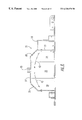
- FIG. 2 shows the volatiles analyzer 10 of the present invention in an open position.
- FIG. 2 illustrates that the invention includes an analytical pan balance of which at least the balance pan 20 is present in the cavity.
- the term “balance pan” is used in its broadest sense and does not literally have to be a pan.
- the pan is preferably formed of a framework, often of a material such as plastic, that is substantially permeable or even transparent to microwave radiation so as not to otherwise interfere with the processes of the device.
- a sample pad (not shown) is placed on top of the pan 20 and a sample is in turn placed on top of the sample pad.
- a second sample pad is placed over the sample to prevent splattering during the heating process.
- the preferred sample pads are preferably formed of glass fibers, although any material is acceptable that does not otherwise interfere with the microwaves or other aspects of the process.
- balances are generally well understood in the chemical arts and will not be described in detail herein.
- the balance should be selected so as to avoid interfering with the propagation of microwaves in the cavity in any undesired fashion.
- Various balances are available from, or can be readily custom-designed by, manufacturers such as Mettler Toledo (Mettler Toledo International, Inc., Worthington, Ohio, USA). Some such balances can measure with an accuracy approaching 0.0000001 gram (g). For most moisture determinations on small samples an accuracy of 0.0001 g (i.e., 0.1 milligram) is preferred.
- FIG. 2 also shows the cavity broadly designated at 21 which in the invention forms a polyhedron that focuses microwave energy of the predetermined frequency generated by the source (FIG. 3) on the balance pan 20 while supporting a plurality of TM and TE modes in the cavity.
- the invention greatly enhances the efficiency of the heating process, even though the cavity itself is much smaller than in earlier devices.
- FIG. 2 also shows the port 22 that permits entry of microwave energy from the waveguide (FIG. 3) into the cavity 21 .
- the port 22 is the sole entry for microwaves between the waveguide and the cavity 21 .
- the waveguide 23 is a rectangular solid and the port 22 is a longitudinal slot positioned in one face of the waveguide 21 and oriented neither parallel nor perpendicular to any of the angles forming the rectangular solid waveguide.
- FIG. 2 also illustrates that the invention can be understood in another sense as a cavity for a microwave device that comprises a polyhedron in which eight of its faces form a regular octagon.
- the words “polyhedron,” “octagon,” and “regular” are all used in their ordinary and dictionary sense in this specification and in the claims.
- a polyhedron is a three-dimensional geometrical solid with a plurality of planar faces.
- An octagon is a two-dimensional figure with eight linear sides.
- a regular octagon is an eight-sided two-dimensional figure in which each of the eight sides are equal in length and all of the eight angles are equal to one another.
- FIG. 2 also shows that in the illustrated embodiment, one face is a regular octagon illustrated as 23 and comprises the bottom face of the cavity 21 .
- FIG. 2 also illustrates that in the preferred embodiment, the polyhedron has 12 sides, eight of which ( 19 , 24 , 25 , 29 - 31 , and 38 - 39 ) are both joined to and perpendicular to the regular octagon face 23 .
- the polyhedron cavity also includes two faces, 26 and 28 that are both nonparallel and nonperpendicular to the other ten faces of the 12-sided polygon.
- the parallel face 27 (i.e., parallel to the regular octagon face) is joined to two of the perpendicular faces that are respectively parallel to one another, the nonparallel and nonperpendicular faces are each joined to the parallel face 26 , and the nonparallel and nonperpendicular faces are each joined to the perpendicular faces.
- FIG. 2 illustrates, the eight sides 19 , 24 , 25 , 29 - 31 , and 38 - 39 form a regular octagon regardless of the top and bottom geometry of the cavity 21 .
- the illustrated embodiment shows the bottom face 23 as being planar and a regular octagon, the invention is not limited to such an arrangement, and the bottom portion of the cavity could be nonplanar.
- the modes and focusing of the microwaves depend on the waveguide, the port from the waveguide to the cavity, and the cavity geometry, and not upon visual references or orientations such as “up” or “down” or the “top,” “bottom,” or “sides” of the cavity. Such terms are used herein in conjunction with the drawings to illustrate the invention rather than to limit its scope.
- FIG. 2 also shows a number of items that are the same as and were described with respect to FIG. 1, and that will not be otherwise described with respect to FIG. 2 .
- FIG. 3 illustrates the source and waveguide as well as other aspects of the invention that have already been referred to.
- the source of microwave radiation typically comprises a magnetron illustrated at 32 in FIG. 3 .
- the source can, however, comprise a klystron or a solid-state device.
- the source 32 is in communication with the waveguide 23 which in turn is in communication with the cavity 21 .
- FIG. 3 also illustrates a cooling system 33 which takes the form of a pan (FIG. 4 ).
- FIG. 3 also illustrates that in preferred embodiments, the moisture analyzer includes an infrared sensor 34 positioned with respect to the cavity 21 to measure the temperature of a sample on the balance pan 20 .
- the infrared sensor 43 is in electronic communication with means for moderating the microwave power in the cavity based upon the measured temperature.
- the moderation of temperature can be as simple as temporarily turning off the power from the magnetron 32 , or it can be a more sophisticated control using, for example, a switching power supply.
- the basic use of the infrared sensor, and its advantages for processing certain types of items, are set forth in more detail in commonly assigned and copending application Ser. No. 09/156,086, filed Sep. 17, 1998, the contents of which are incorporated entirely herein by reference.
- the use of the switching power supply to control microwave energy is likewise set forth in co-pending and commonly assigned application Ser. No. 09/063,545, filed Apr. 21, 1998, which is likewise incorporated entirely herein by reference.
- the moisture analyzer of the present invention typically further comprises a processor (not shown) in electronic communication with the balance for calculating the expected final weight of a sample based upon two or more measurements of the weight at discrete time intervals as the weight changes under the influence of microwave radiation upon the sample.
- the algorithms for calculating such final weight based on the weight change are generally well understood in this art and will not be set forth in detail herein. An early version is set forth, by way of example and not limitation, in U.S. Pat. Nos. 4,438,500 and 4,457,632, which are commonly assigned with the present application. Indeed, the use of particular algorithms and processor logic are often the choice of individual designers and can be carried out by those of ordinary skill in this art without undue experimentation.
- Dorf The Electrical Engineering Handbook, 2 d Ed . (CRC Press 1997), contains extensive discussions of electronic controls, circuits, and processor logic.
- One of the advantageous features of the invention is its capacity of the cavity for supporting a plurality of TM and TE modes at the wavelengths produced by the source.
- a mode is one of the various possible patterns of propagating or standing electromagnetic fields in a particular waveguide or cavity.
- a mode is characterized by its frequency, polarization, electric field strength, and magnetic field strength.
- the distribution of modes in a cavity will always satisfy Maxwell's equations and can be calculated to a fairly accurate extent, particularly using the available computational capacity of modern microprocessors.
- the term “field” is used in its usual sense to indicate the volume of influence of a physical phenomenon expressed as vectors.
- TM and TE modes refer to transverse electric and transverse magnetic modes.
- a transverse mode is one whose field vectors, whether electric or magnetic, are both normal to the direction of propagation of the wave energy.
- FIG. 4 illustrates the power supply 34 for the magnetron 32 as well as a clearer illustration of the pan 33 .
- FIG. 4 also illustrates the power switch 35 which is also referred to as a power entry module.
- a series of sub-D connectors 36 , 37 , and 40 provide for optional communication with stand-alone printers or computers or similar devices.
- the sub-D connectors 36 , 37 , and 40 provide parallel and serial connections in a manner well understood by those of ordinary skill in these arts and the nature of the connections will not be otherwise explained in detail.
- FIG. 4 also illustrates the printer portion 41 of the device which, if desired, can take the results from any particular test, and print them out all on a paper tape.
- FIG. 4 also illustrates a number of the items which have already been described, and which carry corresponding numerals in FIG. 4, but which will not be otherwise described in detail.
- FIG. 5 is a perspective view of the cover portion 11 of the analyzer 10 , and showing a view looking upwards into the cavity 21 .
- FIG. 5 illustrates the slot 22 , the polyhedron shape of the cavity, and also illustrates the air shield 42 that is used in preferred embodiments of the invention.
- the nature, structure, function, and operation of the air shield 42 are set forth in greater detail in co-pending and commonly assigned application Ser. No. 09/397,825, filed concurrently herewith for “Microwave Apparatus and Method for Achieving Accurate Weight Measurements,” the contents of which are incorporated entirely herein by reference.
- FIG. 6 is a top plan view of the cavity of the present invention and particularly illustrates the regular octagon shape of the bottom place 23 of the cavity, which in turn defines the cross-sectional shape of the cavity as taken from this view.
- FIG. 6 also shows the waveguide 18 adjacent to the cavity 21 .
- FIG. 7 is a front elevational view of the cavity 21 , and shows the perpendicular sides 19 , 24 , 25 , 29 - 31 , 38 , and 39 , as well as one of the nonparallel sides 26 , which, in preferred embodiments of the invention, is perforated to allow for an airflow through the cavity 21 while the moisture analysis is taking place.
- FIG. 8 is a cross-sectional view of the cavity 21 and showing the cross-sectional profile of the air shield 42 in one of its preferred positions.
- FIG. 9 is a bottom plan view of the cover portion 11 , the cavity 21 , and the air shield 42 .
- FIG. 9 illustrates that both of the nonparallel, nonperpendicular sides are perforated to encourage the desired airflow, or airflow that can be enhanced using the fan 33 .
- FIG. 10 illustrates a preferred embodiment of the air shield 42 which is generally formed of a grid-like framework 44 which carries either a single, or a plurality of moisture absorbent pads 45 .
- these pads absorb water vapor driven from a heated sample and allow it to recondense.
- the shield 42 moderates the flow of gases through the cavity that could otherwise disturb the accuracy of the balance pan.
- water vapor is affected differently by microwaves than liquid water and thus the absorbent pads provide a location where the water vapor can recondense, again be heated by the microwaves, and then be carried off by the fan.
- the fan preferably draws an airflow across the upper portions of the cavity 21 generally perpendicular to the expected flow of rising water vapor from the sample.
- the combination of the airflow and the shield help draw off the water vapor in a manner that disturbs the balance pan the least, and preferably not at all.
Abstract
Description
Claims (21)
Priority Applications (7)
| Application Number | Priority Date | Filing Date | Title |
|---|---|---|---|
| US09/398,129 US6320170B1 (en) | 1999-09-17 | 1999-09-17 | Microwave volatiles analyzer with high efficiency cavity |
| JP2001523847A JP4777566B2 (en) | 1999-09-17 | 2000-09-16 | Microwave volatile analyzer with high efficiency cavity |
| CA002384882A CA2384882C (en) | 1999-09-17 | 2000-09-16 | Microwave volatiles analyzer with high efficiency cavity |
| EP00965009.4A EP1214582B9 (en) | 1999-09-17 | 2000-09-16 | Microwave volatiles analyzer with high efficiency cavity |
| PCT/US2000/025199 WO2001020312A2 (en) | 1999-09-17 | 2000-09-16 | Microwave volatiles analyzer with high efficiency cavity |
| AU75804/00A AU7580400A (en) | 1999-09-17 | 2000-09-16 | Microwave volatiles analyzer with high efficiency cavity |
| US09/891,027 US6521876B2 (en) | 1999-09-17 | 2001-06-25 | Microwave volatiles analyzer with high efficiency cavity |
Applications Claiming Priority (1)
| Application Number | Priority Date | Filing Date | Title |
|---|---|---|---|
| US09/398,129 US6320170B1 (en) | 1999-09-17 | 1999-09-17 | Microwave volatiles analyzer with high efficiency cavity |
Related Child Applications (1)
| Application Number | Title | Priority Date | Filing Date |
|---|---|---|---|
| US09/891,027 Division US6521876B2 (en) | 1999-09-17 | 2001-06-25 | Microwave volatiles analyzer with high efficiency cavity |
Publications (1)
| Publication Number | Publication Date |
|---|---|
| US6320170B1 true US6320170B1 (en) | 2001-11-20 |
Family
ID=23574099
Family Applications (2)
| Application Number | Title | Priority Date | Filing Date |
|---|---|---|---|
| US09/398,129 Expired - Lifetime US6320170B1 (en) | 1999-09-17 | 1999-09-17 | Microwave volatiles analyzer with high efficiency cavity |
| US09/891,027 Expired - Lifetime US6521876B2 (en) | 1999-09-17 | 2001-06-25 | Microwave volatiles analyzer with high efficiency cavity |
Family Applications After (1)
| Application Number | Title | Priority Date | Filing Date |
|---|---|---|---|
| US09/891,027 Expired - Lifetime US6521876B2 (en) | 1999-09-17 | 2001-06-25 | Microwave volatiles analyzer with high efficiency cavity |
Country Status (6)
| Country | Link |
|---|---|
| US (2) | US6320170B1 (en) |
| EP (1) | EP1214582B9 (en) |
| JP (1) | JP4777566B2 (en) |
| AU (1) | AU7580400A (en) |
| CA (1) | CA2384882C (en) |
| WO (1) | WO2001020312A2 (en) |
Cited By (13)
| Publication number | Priority date | Publication date | Assignee | Title |
|---|---|---|---|---|
| US20020035792A1 (en) * | 1998-05-27 | 2002-03-28 | Scalese Robert F. | Microwave moisture analyzer: apparatus and method |
| US6495825B1 (en) * | 1999-12-22 | 2002-12-17 | International Business Machines Corporation | Apparatus for photo exposure of materials with subsequent capturing of volatiles for analysis |
| US20030199099A1 (en) * | 2002-04-19 | 2003-10-23 | King Edward Earl | Microwave assisted chemical synthesis instrument with controlled pressure release |
| US20040101441A1 (en) * | 2002-11-26 | 2004-05-27 | Cem Corporation | Pressure measurement and relief for microwave-assisted chemical reactions |
| US6880968B1 (en) * | 1999-10-29 | 2005-04-19 | Roche Diagnostics Gmbh | Test element analysis system |
| US20050121307A1 (en) * | 2003-12-09 | 2005-06-09 | Cem Corporation | Method and Apparatus for Microwave Assisted High Throughput High Pressure Chemical Synthesis |
| US20060263900A1 (en) * | 2000-06-23 | 2006-11-23 | Collins Michael J | Method and apparatus for rapid fat content determination |
| US20070062934A1 (en) * | 2005-08-23 | 2007-03-22 | King Edward E | Real-time imaging and spectroscopy during microwave assisted chemistry |
| US20070256479A1 (en) * | 2006-04-25 | 2007-11-08 | Mettler-Toledo Ag | Gravimetric moisture measurement instrument |
| CN104181073A (en) * | 2014-08-22 | 2014-12-03 | 中国农业科学院农产品加工研究所 | Dynamic analysis device for volatile substances of materials |
| USD775977S1 (en) * | 2015-09-22 | 2017-01-10 | Ohaus Instruments (Changzhou) Co., Ltd | Moisture analyzer |
| USD781162S1 (en) * | 2015-09-08 | 2017-03-14 | Mettler-Toledo Gmbh | Moisture analyzer |
| USD946424S1 (en) * | 2019-11-25 | 2022-03-22 | Shizuoka Seiki Co., Ltd. | Moisture meter |
Families Citing this family (6)
| Publication number | Priority date | Publication date | Assignee | Title |
|---|---|---|---|---|
| US7041947B2 (en) * | 2003-09-02 | 2006-05-09 | Cem Corporation | Controlled flow instrument for microwave assisted chemistry with high viscosity liquids and heterogeneous mixtures |
| US6989519B2 (en) * | 2003-09-02 | 2006-01-24 | Cem Corporation | Controlled flow instrument for microwave assisted chemistry with high viscosity liquids and heterogeneous mixtures |
| EP1850110A1 (en) * | 2006-04-25 | 2007-10-31 | Mettler-Toledo AG | Measuring device for gravimetric moisture determination |
| EP1912046A1 (en) * | 2006-10-11 | 2008-04-16 | Mettler-Toledo AG | Gravimetric moisture analyser |
| US20170074766A1 (en) | 2015-09-11 | 2017-03-16 | Cem Corporation | Moisture and volatiles analyzer |
| JP7263976B2 (en) * | 2019-08-21 | 2023-04-25 | 株式会社島津製作所 | Differential thermal/thermogravimetric simultaneous measurement device |
Citations (26)
| Publication number | Priority date | Publication date | Assignee | Title |
|---|---|---|---|---|
| US3252115A (en) | 1963-04-08 | 1966-05-17 | Trw Inc | Tuning arrangement |
| US3461261A (en) | 1966-10-31 | 1969-08-12 | Du Pont | Heating apparatus |
| US3590202A (en) | 1970-02-24 | 1971-06-29 | Bechtel Corp | Construction for tuning microwave heating applicator |
| US3590201A (en) | 1969-05-14 | 1971-06-29 | Aeroquip Corp | Photoelectric control systems for brazing tools |
| US3890825A (en) * | 1972-07-03 | 1975-06-24 | Hobart Corp | Analysis of comminuted meat products |
| US4006338A (en) * | 1975-12-31 | 1977-02-01 | General Electric Company | Microwave heating apparatus with improved multiple couplers and solid state power source |
| US4343976A (en) | 1979-03-19 | 1982-08-10 | U.S. Philips Corporation | Energy feed system for a microwave oven |
| US4413168A (en) | 1980-09-24 | 1983-11-01 | Raytheon Company | Heating time coupling factor for microwave oven |
| US4438500A (en) | 1973-07-20 | 1984-03-20 | Cem Corporation | Rapid volatility analyzer |
| US4457632A (en) | 1973-07-20 | 1984-07-03 | Cem Corporation | Automatic volatility computer |
| US4562409A (en) | 1983-03-29 | 1985-12-31 | Fujitsu Limited | Cavity resonator coupling-type power distributor/power combiner |
| US4883570A (en) | 1987-06-08 | 1989-11-28 | Research-Cottrell, Inc. | Apparatus and method for enhanced chemical processing in high pressure and atmospheric plasmas produced by high frequency electromagnetic waves |
| US4908486A (en) * | 1986-06-05 | 1990-03-13 | Nearctic Research Centre | Resonant cavity of a microwave drier |
| US5250773A (en) | 1991-03-11 | 1993-10-05 | Mcdonnell Douglas Corporation | Microwave heating device |
| US5280216A (en) | 1991-02-12 | 1994-01-18 | Thomson Tubes Electroniques | Mode converter and power splitter for microwave tubes |
| US5308944A (en) | 1990-06-14 | 1994-05-03 | Stone Elander Sharon A | Apparatus and method for microwave treatment of process liquids |
| US5351541A (en) | 1992-01-22 | 1994-10-04 | Charles Stark Draper Laboratories | Microwave resonator accelerometer |
| US5459302A (en) * | 1991-12-23 | 1995-10-17 | Societe Prolabo | Apparatus and process for measuring the temperature of a sample heated in a microwave chamber |
| US5632921A (en) | 1995-06-05 | 1997-05-27 | The Rubbright Group, Inc. | Cylindrical microwave heating applicator with only two modes |
| DE19633245C1 (en) * | 1996-08-17 | 1997-11-27 | Karlsruhe Forschzent | High mode microwave resonator for high temperature treatment of materials |
| US5725951A (en) | 1995-08-28 | 1998-03-10 | Milliken Research Corporation | Lubricant and soil release finish for yarns |
| US5796080A (en) * | 1995-10-03 | 1998-08-18 | Cem Corporation | Microwave apparatus for controlling power levels in individual multiple cells |
| US5834744A (en) * | 1997-09-08 | 1998-11-10 | The Rubbright Group | Tubular microwave applicator |
| WO1999040409A2 (en) | 1998-02-10 | 1999-08-12 | Denver Instrument Company | A microwave moisture analyzer: apparatus and method |
| US6072168A (en) * | 1996-08-17 | 2000-06-06 | Forschungszentrum Karlsruhe Gmbh | Microwave resonator for the high temperature treatment of materials |
| US6084226A (en) * | 1998-04-21 | 2000-07-04 | Cem Corporation | Use of continuously variable power in microwave assisted chemistry |
Family Cites Families (4)
| Publication number | Priority date | Publication date | Assignee | Title |
|---|---|---|---|---|
| US4361744A (en) * | 1981-01-12 | 1982-11-30 | Despatch Industries, Inc. | Microwave process unit |
| CA1270876A (en) | 1984-03-22 | 1990-06-26 | Sueaki Honda | Push-button lever contact switch |
| WO1989010678A1 (en) * | 1988-04-19 | 1989-11-02 | Deakin University | Improved microwave treatment apparatus |
| DE69730571T2 (en) * | 1996-05-17 | 2005-08-18 | Technology Finance Corp. (Pty.) Ltd., Sandton | DIELECTRIC HEATING DEVICE |
-
1999
- 1999-09-17 US US09/398,129 patent/US6320170B1/en not_active Expired - Lifetime
-
2000
- 2000-09-16 WO PCT/US2000/025199 patent/WO2001020312A2/en active Application Filing
- 2000-09-16 CA CA002384882A patent/CA2384882C/en not_active Expired - Fee Related
- 2000-09-16 EP EP00965009.4A patent/EP1214582B9/en not_active Expired - Lifetime
- 2000-09-16 AU AU75804/00A patent/AU7580400A/en not_active Abandoned
- 2000-09-16 JP JP2001523847A patent/JP4777566B2/en not_active Expired - Fee Related
-
2001
- 2001-06-25 US US09/891,027 patent/US6521876B2/en not_active Expired - Lifetime
Patent Citations (26)
| Publication number | Priority date | Publication date | Assignee | Title |
|---|---|---|---|---|
| US3252115A (en) | 1963-04-08 | 1966-05-17 | Trw Inc | Tuning arrangement |
| US3461261A (en) | 1966-10-31 | 1969-08-12 | Du Pont | Heating apparatus |
| US3590201A (en) | 1969-05-14 | 1971-06-29 | Aeroquip Corp | Photoelectric control systems for brazing tools |
| US3590202A (en) | 1970-02-24 | 1971-06-29 | Bechtel Corp | Construction for tuning microwave heating applicator |
| US3890825A (en) * | 1972-07-03 | 1975-06-24 | Hobart Corp | Analysis of comminuted meat products |
| US4438500A (en) | 1973-07-20 | 1984-03-20 | Cem Corporation | Rapid volatility analyzer |
| US4457632A (en) | 1973-07-20 | 1984-07-03 | Cem Corporation | Automatic volatility computer |
| US4006338A (en) * | 1975-12-31 | 1977-02-01 | General Electric Company | Microwave heating apparatus with improved multiple couplers and solid state power source |
| US4343976A (en) | 1979-03-19 | 1982-08-10 | U.S. Philips Corporation | Energy feed system for a microwave oven |
| US4413168A (en) | 1980-09-24 | 1983-11-01 | Raytheon Company | Heating time coupling factor for microwave oven |
| US4562409A (en) | 1983-03-29 | 1985-12-31 | Fujitsu Limited | Cavity resonator coupling-type power distributor/power combiner |
| US4908486A (en) * | 1986-06-05 | 1990-03-13 | Nearctic Research Centre | Resonant cavity of a microwave drier |
| US4883570A (en) | 1987-06-08 | 1989-11-28 | Research-Cottrell, Inc. | Apparatus and method for enhanced chemical processing in high pressure and atmospheric plasmas produced by high frequency electromagnetic waves |
| US5308944A (en) | 1990-06-14 | 1994-05-03 | Stone Elander Sharon A | Apparatus and method for microwave treatment of process liquids |
| US5280216A (en) | 1991-02-12 | 1994-01-18 | Thomson Tubes Electroniques | Mode converter and power splitter for microwave tubes |
| US5250773A (en) | 1991-03-11 | 1993-10-05 | Mcdonnell Douglas Corporation | Microwave heating device |
| US5459302A (en) * | 1991-12-23 | 1995-10-17 | Societe Prolabo | Apparatus and process for measuring the temperature of a sample heated in a microwave chamber |
| US5351541A (en) | 1992-01-22 | 1994-10-04 | Charles Stark Draper Laboratories | Microwave resonator accelerometer |
| US5632921A (en) | 1995-06-05 | 1997-05-27 | The Rubbright Group, Inc. | Cylindrical microwave heating applicator with only two modes |
| US5725951A (en) | 1995-08-28 | 1998-03-10 | Milliken Research Corporation | Lubricant and soil release finish for yarns |
| US5796080A (en) * | 1995-10-03 | 1998-08-18 | Cem Corporation | Microwave apparatus for controlling power levels in individual multiple cells |
| DE19633245C1 (en) * | 1996-08-17 | 1997-11-27 | Karlsruhe Forschzent | High mode microwave resonator for high temperature treatment of materials |
| US6072168A (en) * | 1996-08-17 | 2000-06-06 | Forschungszentrum Karlsruhe Gmbh | Microwave resonator for the high temperature treatment of materials |
| US5834744A (en) * | 1997-09-08 | 1998-11-10 | The Rubbright Group | Tubular microwave applicator |
| WO1999040409A2 (en) | 1998-02-10 | 1999-08-12 | Denver Instrument Company | A microwave moisture analyzer: apparatus and method |
| US6084226A (en) * | 1998-04-21 | 2000-07-04 | Cem Corporation | Use of continuously variable power in microwave assisted chemistry |
Non-Patent Citations (1)
| Title |
|---|
| Varlamova N. A. et al: "On the Quality Factor of Cavity Resonators of Different Shapes", Telecommunications and Radio Engineering, US, Begell House, Inc., New York, NY, Vol. 52, No. 2, 1998, pp. 79-85. * |
Cited By (32)
| Publication number | Priority date | Publication date | Assignee | Title |
|---|---|---|---|---|
| US20020035792A1 (en) * | 1998-05-27 | 2002-03-28 | Scalese Robert F. | Microwave moisture analyzer: apparatus and method |
| US7148455B2 (en) * | 1998-05-27 | 2006-12-12 | Denver Instrument Company | Microwave moisture analyzer: apparatus and method |
| US6880968B1 (en) * | 1999-10-29 | 2005-04-19 | Roche Diagnostics Gmbh | Test element analysis system |
| US6495825B1 (en) * | 1999-12-22 | 2002-12-17 | International Business Machines Corporation | Apparatus for photo exposure of materials with subsequent capturing of volatiles for analysis |
| US20060263900A1 (en) * | 2000-06-23 | 2006-11-23 | Collins Michael J | Method and apparatus for rapid fat content determination |
| US8530239B2 (en) | 2000-06-23 | 2013-09-10 | Cem Corporation | Sample combination for NMR measurements of fats and oils |
| US20080061056A1 (en) * | 2002-04-19 | 2008-03-13 | King Edward E | Microwave Assisted Chemical Synthesis Instrument With Controlled Pressure Release |
| US20030199099A1 (en) * | 2002-04-19 | 2003-10-23 | King Edward Earl | Microwave assisted chemical synthesis instrument with controlled pressure release |
| US8426783B2 (en) | 2002-04-19 | 2013-04-23 | Cem Corporation | Microwave assisted chemical synthesis instrument with controlled pressure release |
| US7282184B2 (en) | 2002-04-19 | 2007-10-16 | Cem Corporation | Microwave assisted chemical synthesis instrument with controlled pressure release |
| US20110042372A1 (en) * | 2002-04-19 | 2011-02-24 | Edward Earl King | Microwave Assisted Chemical Synthesis Instrument with Controlled Pressure Release |
| US7829828B2 (en) | 2002-04-19 | 2010-11-09 | Cem Corporation | Microwave assisted chemical synthesis instrument with controlled pressure release |
| US7820951B2 (en) | 2002-04-19 | 2010-10-26 | Cem Corporation | Microwave assisted chemical synthesis instrument with controlled pressure release |
| US20080053987A1 (en) * | 2002-04-19 | 2008-03-06 | King Edward E | Microwave Assisted Chemical Synthesis Instrument With Controlled Pressure Release |
| US20040101441A1 (en) * | 2002-11-26 | 2004-05-27 | Cem Corporation | Pressure measurement and relief for microwave-assisted chemical reactions |
| US7144739B2 (en) | 2002-11-26 | 2006-12-05 | Cem Corporation | Pressure measurement and relief for microwave-assisted chemical reactions |
| US20070295594A1 (en) * | 2003-12-09 | 2007-12-27 | Hargett Wyatt P Jr | Method and Apparatus for Microwave Assisted High Throughput High Pressure Chemical Synthesis |
| US20050121307A1 (en) * | 2003-12-09 | 2005-06-09 | Cem Corporation | Method and Apparatus for Microwave Assisted High Throughput High Pressure Chemical Synthesis |
| US7307248B2 (en) | 2003-12-09 | 2007-12-11 | Cem Corporation | Method and apparatus for microwave assisted high throughput high pressure chemical synthesis |
| US20080053989A1 (en) * | 2003-12-09 | 2008-03-06 | Hargett Wyatt P Jr | Method and Apparatus for Microwave Assisted High Throughput High Pressure Chemical Synthesis |
| US7816633B2 (en) | 2003-12-09 | 2010-10-19 | Cem Corporation | Method and apparatus for microwave assisted high throughput high pressure chemical synthesis |
| US20080267841A1 (en) * | 2005-08-23 | 2008-10-30 | Cem Corporation | Real-time imaging and spectroscopy during microwave assisted chemistry |
| US20080267839A1 (en) * | 2005-08-23 | 2008-10-30 | Cem Corporation | Real-time imaging and spectroscopy during microwave assisted chemistry |
| US20070062934A1 (en) * | 2005-08-23 | 2007-03-22 | King Edward E | Real-time imaging and spectroscopy during microwave assisted chemistry |
| US7405381B2 (en) | 2005-08-23 | 2008-07-29 | Cem, Corporation | Real-time imaging and spectroscopy during microwave assisted chemistry |
| US7851712B2 (en) * | 2006-04-25 | 2010-12-14 | Mettler-Toledo Ag | Gravimetric moisture measurement instrument |
| US20070256479A1 (en) * | 2006-04-25 | 2007-11-08 | Mettler-Toledo Ag | Gravimetric moisture measurement instrument |
| CN104181073A (en) * | 2014-08-22 | 2014-12-03 | 中国农业科学院农产品加工研究所 | Dynamic analysis device for volatile substances of materials |
| CN104181073B (en) * | 2014-08-22 | 2016-08-03 | 中国农业科学院农产品加工研究所 | A kind of dynamic analytical equipment of material volatile material |
| USD781162S1 (en) * | 2015-09-08 | 2017-03-14 | Mettler-Toledo Gmbh | Moisture analyzer |
| USD775977S1 (en) * | 2015-09-22 | 2017-01-10 | Ohaus Instruments (Changzhou) Co., Ltd | Moisture analyzer |
| USD946424S1 (en) * | 2019-11-25 | 2022-03-22 | Shizuoka Seiki Co., Ltd. | Moisture meter |
Also Published As
| Publication number | Publication date |
|---|---|
| CA2384882A1 (en) | 2001-03-22 |
| US6521876B2 (en) | 2003-02-18 |
| EP1214582B1 (en) | 2014-07-16 |
| AU7580400A (en) | 2001-04-17 |
| CA2384882C (en) | 2006-11-28 |
| WO2001020312A2 (en) | 2001-03-22 |
| WO2001020312A3 (en) | 2001-11-22 |
| EP1214582B9 (en) | 2015-02-18 |
| US20010032845A1 (en) | 2001-10-25 |
| EP1214582A2 (en) | 2002-06-19 |
| JP4777566B2 (en) | 2011-09-21 |
| JP2003509690A (en) | 2003-03-11 |
Similar Documents
| Publication | Publication Date | Title |
|---|---|---|
| US6320170B1 (en) | Microwave volatiles analyzer with high efficiency cavity | |
| CA2343195C (en) | Method and apparatus for measuring volatile content | |
| US7015441B2 (en) | Microwave heating apparatus | |
| US3813918A (en) | Methods and apparatus using microwaves for material characteristics measurements | |
| EP1297327B1 (en) | Microwave assisted content analyzer | |
| US6411103B1 (en) | Stray-field sensor | |
| US4106329A (en) | Solid or water quantity measurement apparatus using microwaves | |
| US10527533B2 (en) | Moisture and volatiles analyzer | |
| US4438500A (en) | Rapid volatility analyzer | |
| Carlini et al. | Measurement method and apparatus for monitoring the kinetics of polymerization and crosslinking reactions by microwave dielectrometry | |
| Thompson et al. | Analysis and design of a re-entrant microwave cavity for the characterisation of single wheat grain kernels | |
| USRE32861E (en) | Automatic volatility computer | |
| JP7109945B2 (en) | Laboratory test device | |
| Holmes et al. | In-kiln moisture content measurement of timber using a waveguide aperture array | |
| JPH051987A (en) | Measurement device for moisture or volatile component | |
| Pathak et al. | Development of an integrated multi-grid 3D FDTD and finite-difference heat transfer code to simulate microwave drying in multimode cavities |
Legal Events
| Date | Code | Title | Description |
|---|---|---|---|
| AS | Assignment |
Owner name: CEM CORPORATION, NORTH CAROLINA Free format text: ASSIGNMENT OF ASSIGNORS INTEREST;ASSIGNORS:JENNINGS, WILLIAM EDWARD;BARRETT, MATTHEW DONALD;KING, EDWARD EARL;REEL/FRAME:010558/0206 Effective date: 20000110 |
|
| AS | Assignment |
Owner name: BANC OF AMERICA COMMERCIAL FINANCE CORPORATION, AS Free format text: NOTICE OF GRANT OF SECURITY INTEREST;ASSIGNOR:CEM LIMITED, LLC;REEL/FRAME:010892/0430 Effective date: 20000531 |
|
| AS | Assignment |
Owner name: CEM LIMITED, L.L.C., NORTH CAROLINA Free format text: ASSIGNMENT OF ASSIGNORS INTEREST;ASSIGNOR:CEM CORPORATION;REEL/FRAME:010892/0674 Effective date: 20000531 |
|
| STCF | Information on status: patent grant |
Free format text: PATENTED CASE |
|
| AS | Assignment |
Owner name: CEM CORPORATION, NORTH CAROLINA Free format text: MERGER;ASSIGNOR:CEM LIMITED, LLC;REEL/FRAME:013248/0680 Effective date: 20001020 |
|
| FEPP | Fee payment procedure |
Free format text: PAT HOLDER CLAIMS SMALL ENTITY STATUS, ENTITY STATUS SET TO SMALL (ORIGINAL EVENT CODE: LTOS); ENTITY STATUS OF PATENT OWNER: SMALL ENTITY |
|
| REFU | Refund |
Free format text: REFUND - PAYMENT OF MAINTENANCE FEE, 4TH YEAR, LARGE ENTITY (ORIGINAL EVENT CODE: R1551); ENTITY STATUS OF PATENT OWNER: SMALL ENTITY |
|
| FPAY | Fee payment |
Year of fee payment: 4 |
|
| FPAY | Fee payment |
Year of fee payment: 8 |
|
| FPAY | Fee payment |
Year of fee payment: 12 |