US6321112B1 - Device to provide data as a guide to health management - Google Patents
Device to provide data as a guide to health management Download PDFInfo
- Publication number
- US6321112B1 US6321112B1 US09/340,940 US34094099A US6321112B1 US 6321112 B1 US6321112 B1 US 6321112B1 US 34094099 A US34094099 A US 34094099A US 6321112 B1 US6321112 B1 US 6321112B1
- Authority
- US
- United States
- Prior art keywords
- impedance
- electrodes
- pair
- electrode
- foot
- Prior art date
- Legal status (The legal status is an assumption and is not a legal conclusion. Google has not performed a legal analysis and makes no representation as to the accuracy of the status listed.)
- Expired - Fee Related
Links
Images


Classifications
-
- A—HUMAN NECESSITIES
- A61—MEDICAL OR VETERINARY SCIENCE; HYGIENE
- A61B—DIAGNOSIS; SURGERY; IDENTIFICATION
- A61B5/00—Measuring for diagnostic purposes; Identification of persons
- A61B5/48—Other medical applications
- A61B5/4869—Determining body composition
- A61B5/4872—Body fat
-
- A—HUMAN NECESSITIES
- A61—MEDICAL OR VETERINARY SCIENCE; HYGIENE
- A61B—DIAGNOSIS; SURGERY; IDENTIFICATION
- A61B5/00—Measuring for diagnostic purposes; Identification of persons
- A61B5/05—Detecting, measuring or recording for diagnosis by means of electric currents or magnetic fields; Measuring using microwaves or radio waves
- A61B5/053—Measuring electrical impedance or conductance of a portion of the body
- A61B5/0537—Measuring body composition by impedance, e.g. tissue hydration or fat content
Definitions
- This invention concerns a device and method to provide data about fat content of a human body as a guide to health management. More specifically, a technique of determining such values as total internal body fat, nonfat body mass, ratio of body fat, water mass, and basic metabolic rate are described. The present invention also describes calculating the visceral fat mass and the ratio of visceral-to-subcutaneous fat. Based on the results of these calculations, the device provides data to be used as a guide for health management.
- the equipment includes a measuring device 1 connected to electrodes 2 and 3 by lead wires 6 , and which apply a high-frequency signal; and electrodes 4 and 5 , which measure the resistance of the body.
- the patient is made to lie on a bed, electrodes 2 and 3 are attached to the patient's right hand and right foot, and electrodes 4 and 5 , which measure the resistance of the body, are attached to the right hand and foot close to electrodes 2 and 3 , respectively.
- a high-frequency signal is applied to electrodes 2 and 3 by device 1 , causing a current to pass into the patient's body.
- the potential difference between electrodes 4 and 5 is measured, and the impedance of the patient's body can be obtained from this potential difference and the strength of the current which was passed.
- the objective of the present invention is to provide a device which can supply data that would be useful as a guide for home health management.
- the present invention allows the patient to easily be able to measure the impedance developed across the body.
- the device determines the amount and ratio of visceral fat and the type of obesity. It would be compact, light, and inexpensive, and the accuracy of its measurements would be high.
- An individual is able to use the device in the privacy of their own home.
- the device to provide data as a guide to health management includes: 1) a portable main unit with grip area for the right and left hands, furnished on either end of the main unit, each of which has an electrode to apply a high-frequency signal and an electrode to measure the resistance of the body.
- a foot electrode unit is connected by a cable to the aforesaid main unit, and has electrodes to apply high-frequency signals and electrodes to measure the electrical potential developed across the body.
- the portable main unit mentioned above has a first high frequency generator that generates a high-frequency signal which passes through both the shallow part of the body (where subcutaneous fat is located) and the deeper part of body (where visceral fat is located).
- a second frequency generator generates high-frequency signal which passes mainly in the deeper part of the body.
- An electrode selecting device selects which two of the aforesaid pairs of electrodes will be used by a switching operation.
- a frequency selecting device switches frequencies to select one of the aforesaid series of high-frequency signals, and it applies them between the first electrodes of the selected pairs.
- the impedance between the two pairs of electrodes from the electrical potential detected across the respective second electrode in each of the pairs is detected, and this is used to calculate the visceral fat mass based on the impedances measured when the two high-frequency signals are applied.
- Other specific physical data which have been entered independently, such as weight, can also be used.
- the patient uses this device by grasping the grips with both hands so that each hand makes contact with the two electrodes in the grip.
- the user steps onto the stand, causing the sole of each foot to make contact with the two foot electrodes.
- the portion of the impedance attributable to the limbs can be calculated by adding the value of the impedance between the feet (Z 2f ) to the value of the impedance between the hands (Z 2h ). These values are subtracted from the value of the impedance between hand and foot (Z 2b ) to obtain the impedance value for the thoracic region alone (Z 2s ). From this impedance data and specific physical data input by the patient, the visceral fat mass can be calculated:
- Another aspect of this application calculates, from the values for total body fat mass and visceral fat mass obtained by the device discussed above, a value for subcutaneous fat mass, and calculates the ratio of visceral-to-subcutaneous fat masses. From this ratio, the present invention allows a determination of whether the obesity is of the subcutaneous or visceral type.
- Another aspect of this application provides elements including: 1) a portable main unit; 2) grips for the right and left hands, furnished on either end of the main unit, each of which has an first electrode to apply a high-frequency signal and an second electrode to measure the resistance of the body; 3) a foot electrode unit, connected by a cable to the aforesaid main unit, which has electrodes to apply high-frequency signals and electrodes to measure the electrical potential developed across the body.
- the portable main unit mentioned above is equipped with the following: 1) a high frequency generator has a high-frequency signal which passes through both the shallow part of the body (where subcutaneous fat is located) and the deeper part of the body (where visceral fat is located), 2) an electrode selecting device including switches connected to establish connections that select any two of the aforesaid first and second electrodes; 3) an impedance measuring device to measure the impedance between the two pairs of electrodes from the electrical potential detected across the respective second electrode in each of the pairs; 4) a estimating device which estimates an waist-to-hip ratio based on the data concerning impedance between the two pairs of electrodes measured by the device for that purpose, and on specific physical data which have been entered independently; and 5) a calculating device to calculate visceral fat mass based on the waist-to-hip ratio which has been estimated.
- This device can, for example, measure the impedance Z f between the patient's feet, the impedance Z h between the patient's hands, and/or the impedance Z b between hand and foot. From these values the impedance Z s of the thoracic region is obtained.
- the device uses the impedance Z fs of the hip region, which is obtained from the hand-to-hand impedance Z h and the foot-to-foot impedance Z f , and the impedance Z s of the thoracic region, to estimate a waist-to-hip ratio. It estimates the visceral fat mass and the visceral-to-subcutaneous fat ratio using this waist-to-hip ratio, the total body fat ratio, the converted fat and other values.
- the present invention allows accurate measurement of body fat ratio and visceral fat mass.
- the measurement is not affected by differences in the density of patients' hands and feet. It provides, in a simple and reliable fashion, a measurement of visceral fat mass, which is a crucial datum in health management.
- This device allows obtaining a value for the subcutaneous fat mass as well as the subcutaneous-to-visceral fat ratio. This allows an evaluation to be made as to whether the patient's obesity is of the subcutaneous or visceral variety.
- This device uses the various measured impedance values to estimate a wastes/hip ratio, and from this estimated waist/hip ratio it calculates an estimate of body fat mass. From this it is able to obtain a value for visceral fat mass, a crucial datum in health management.
- the device can provide, in a simple and reliable fashion, such critical values as the proportional index, the amount and ratio of visceral fat within the total fat mass, and whether the obesity is of the subcutaneous or visceral variety.
- FIG. 1 is a perspective view of the exterior of a device to provide data as a guide to health management which is an ideal embodiment of this invention
- FIG. 2 illustrates the use of that same device
- FIG. 3 is a cross section of the foot electrode unit of the same device, taken on line A—A in FIG. 1;
- FIG. 4 is a block diagram showing a portion of the circuitry in the same device
- FIG. 5 is a block diagram which, together with FIG. 4, illustrates the structure of the circuits in the same embodiment
- FIG. 6 illustrates another way the device of this same embodiment might be used
- FIG. 7 is a circuit diagram illustrating the connections made when the device of the same embodiment is switched to the first frequency and set to the mode for measuring the impedance between left hand and foot;
- FIG. 8 is a circuit diagram illustrating the connections made when the device of the same embodiment is switched to the same frequency and set to the mode for measuring the impedance between the hands;
- FIG. 9 is a circuit diagram illustrating the connections made when the device of the same embodiment is switched to the same frequency and set to the mode for measuring the impedance between the feet;
- FIG. 10 is a circuit diagram illustrating the connections made when the device of the same embodiment is switched to the same frequency and set to the mode for measuring the impedance between the right hand and left foot;
- FIG. 11 is a circuit diagram illustrating the connections made when the device of the same embodiment is switched to the same frequency and set to the mode for measuring the impedance between the left hand and right foot;
- FIG. 12 is a circuit diagram illustrating the connections made when the device of the same embodiment is switched to the same frequency and set to the mode for measuring the impedance between both hands and feet;
- FIG. 13 is a flowchart of the operations performed when the same embodiment uses as its standard mode the measurement of the impedance between one hand and foot;
- FIG. 14 is another flowchart of the operations performed by the same embodiment.
- FIG. 15 is another flowchart of the operations performed by the same embodiment.
- FIG. 16 is a flowchart of the operations performed when the same embodiment uses as its standard mode the measurement of the impedance between both hands and feet;
- FIG. 17 is another flowchart of the measurement operations performed by the same embodiment.
- FIG. 18 is another flowchart of the measurement operations performed by the same embodiment.
- FIG. 19 shows the equivalent circuits of the human body which are relevant to measuring the impedance values used to estimate the waist/hip ratio
- FIG. 20 is a block diagram illustrating the circuits in another ideal embodiment of the device to provide data as a guide to health management of this invention.
- FIG. 21 is a flowchart of the measurement operations performed by this device.
- FIG. 22 is another flowchart of the measurement operations performed by the same device.
- FIG. 23 is another flowchart of the measurement operations performed by the same device.
- FIG. 24 illustrates how the impedance of the body was measured using a technique of the prior art.
- FIG. 25 shows the electrodes used on the patient's hand and foot when the impedance of the body was measured using a technique of the prior art.
- FIG. 1 is a perspective view of the exterior of a device to provide data as a guide to health management.
- the device of this embodiment includes main unit 10 , foot electrode unit 50 , and cable 51 , which connects unit 10 to unit 50 .
- Main unit 10 has body 11 having left and right grips 12 and 13 formed integrally on either side of body 11 .
- the front of body 11 includes power supply switch 14 ; key switches 15 which are used to enter the start command and physical characteristics of the patient such as height and weight; and display 16 , which displays the measurement results and advisory data.
- Display 16 is located in the center of an area between left and right handgrips 12 and 13 .
- Left and right grips 12 and 13 include vertical cylinders on whose surfaces are provided electrodes 17 and 18 between which is applied a high-frequency signal, and electrodes 19 and 20 (see FIG. 4 ), which measure the resistance of the body.
- Foot electrode unit 50 includes flat rectangular sheet 52 , on which are two position guides, including guide 53 for the left foot and guide 54 for the right foot. Each of these guides has two electrodes. A high-frequency signal is applied between electrodes 55 and 56 . The resistance of the body is measured between electrodes 57 and 58 . The top surface of the front end of sheet 52 is partially covered by housing 59 . Display 60 , which is used to monitor the state of the measurement, is seated in this housing. Opening 61 is located toward the front end of sheet 52 and between the foot position guides.
- FIG. 3 shows a cross section along the Line A—A in FIG. 1 .
- Sheet 52 is constructed of surface layer 62 and underlayer 63 .
- Layers 62 and 63 can be composed of PVC, PET, polyethylene, or some similar substance.
- Elastic protrusion 65 is located in the region corresponding to the arch of the foot, in position guide 54 .
- the two electrodes 56 and 58 are formed on elastic protrusion 65 .
- FIG. 3 shows a cross section of the position guide for the right foot; it should be understood that the guide for the left foot has an identical construction.
- Protrusions 64 and 65 are constructed of an elastic sheet made of a material such as silicon rubber.
- Housing 59 can be made of a material like ABS or PVC.
- Cable 51 terminates in connectors 66 and 67 at respective ends thereof which allow connection to main unit 10 and foot electron unit 50 in such a way that it can easily be connected or disconnected.
- FIGS. 4 and 5 show block diagrams of the controlling circuits for this embodiment.
- Differential amplifier 22 receives the electrical potential signals from electrodes 19 and 20 .
- the output of differential amplifier 22 is filtered through band pass filter 23 , which filters out signals of frequencies other than frequency f 0 .
- That output is demodulated by demodulator circuit 24 , which demodulates the high-frequency signal component; then A/D converter 25 converts the analog signals into digital signals input to CPU 28 .
- CPU 28 also has associated ROM 26 and RAM 27 .
- CPU 28 which reads in the input from A/D converter 25 and the data from input unit 15 , including height, weight, age, sex, date and time, and performs the operations necessary to measure the impedance, and extracts advisory data relevant to managing the patient's health.
- Outputs are provided to warning buzzer 29 ; output unit 30 , which transmits to a printer of other peripheral device data such as measurement results.
- Battery 31 serves as the power supply for the device.
- Electrode switch unit 32 a and frequency switch unit 32 b supply inputs to signal generator 21 and differential amplifier 22 to switch selectively among electrodes 17 , 18 , 19 and 20 on grips 12 and 13 and among electrodes 55 , 56 , 57 and 58 on foot electrode unit 50 .
- This input is connected by connector 66 , cable 51 and connector 67 . Switching is accomplished by making or breaking a circuit.
- Electrode switch unit 32 a and frequency switch unit 32 b can include, for example, analog switches or relays.
- the type of switch used must conform to the setting of the measurement mode in CPU 28 : A switch must be chosen which responds to the control signals for electrode and frequency switching carried out by the CPU.
- Signals of frequency f 1 can travel from the subcutaneous fat layer both toward the external tissue (primarily the dermis) and toward the internal tissue (muscle, blood vessels, internal organs, bone, etc.).
- Signals of frequency f 2 travel from the subcutaneous fat layer primarily toward the internal tissue.
- the device described above allows data concerning physical characteristics to be input via input unit 15 .
- the weight can be measured by an ordinary bathroom scale 68 , on which foot electrode unit 50 can be placed, as shown in FIG. 6 .
- the user steps onto foot unit 50 , weighs himself on scale 68 , and enters a current body weight.
- foot electrode unit 50 has an opening 61 through which the user can read the weight from scale 68 while holding main unit 10 , as shown in the drawing.
- a transparent window which allows the weight to be read, may be substituted for this opening.
- foot position guides 53 and 54 are provided on either side of opening 61 on foot electrode unit 50 , and electrodes 55 , 56 , 57 and 58 are placed in these guides.
- the opening 61 has another, more indirect function, of ensuring a degree of separation between the feet.
- connection line I h2 from electrode 18 the electrode which applies a high-frequency signal to the right hand, is connected to one terminal of signal generator 21 a
- connection line I f2 from electrode 55 the electrode which applies a high-frequency signal from the left foot, is connected to the other terminal.
- Connection line E h2 from electrode 20 the electrode which measures the resistance of the right hand, and connection line E f2 from electrode 58 , the electrode which measures the resistance of the right foot, are connected to the two input terminals of differential amplifier 22 .
- Connection line I h1 from electrode 17 the electrode which applies a high-frequency signal to the left hand, and connection line E h1 from electrode 19 , the electrode which measures the resistance of the left hand, are not connected to anything —they are left open.
- Connection line I f1 from electrode 55 the electrode which applies a high-frequency signal to the left foot, and connection line E f1 from electrode 57 , the electrode which measures the resistance of the right foot, are also not connected to anything and are left open.
- a switching control signal from CPU 28 connects the switches in electrode switch unit 32 a as shown in FIG. 7.
- a connection line I h1 from electrode 17 the electrode which applies a high-frequency signal to the left hand, is connected to one terminal of signal generator 21 a
- connection line I f1 from electrode 55 the electrode which applies a high-frequency signal to the left foot
- Connection line E h1 from electrode 19 the electrode which measures the resistance of the left hand
- connection line E f1 from electrode 57 the electrode which measures the resistance of the left foot
- Connection line I h2 from electrode 18 the electrode which applies a high-frequency signal to the right hand
- connection line E h2 from electrode 20 the electrode which measures the resistance of the right hand
- Connection line I f2 from electrode 56 the electrode which applies a high-frequency signal to the right foot
- connection line E f2 from electrode 58 the electrode which measures the resistance of the right foot
- a switching control signal from CPU 28 causes the switches in electrode switch unit 32 a to be connected as shown in FIG. 8 .
- Connection line I h1 from electrode 17 the electrode which applies a high-frequency signal to the left hand, is connected to one terminal of signal generator 21 a
- connection line I h2 from electrode 18 the electrode which applies a high-frequency signal to the right hand, is connected to the other terminal.
- Connection line E h1 from electrode 19 the electrode which measures the resistance of the left hand
- connection line E h2 from electrode 20 the electrode which measures the resistance of the right hand, are connected to the two input terminals of differential amplifier 22 .
- connection lines I f1 , I f2 , E f1 and E f2 which are for the electrodes on the feet, are not connected and are left open.
- a switching control signal from CPU 28 causes the switches in electrode switch unit 32 a to be connected as shown in FIG. 9 . That is, connection line I f1 from electrode 55 , the electrode which applies a high-frequency signal to the left foot, is connected to one terminal of signal generator 21 a , and connection line I f2 from electrode 56 , the electrode which applies a high-frequency signal to the right foot, is connected to the other terminal. Connection line E f1 from electrode 57 , the electrode which measures the resistance of the left foot, and connection line E f2 from electrode 58 , the electrode which measures the resistance of the right foot, are connected to the two input terminals of differential amplifier 22 . In this case, the rule is reversed when measuring the impedance between the hands, and connection lines I h1 , I h2 , E h1 and E 2 , which are for the electrodes on the hands, are not connected and are left open.
- a switching control signal from CPU 28 causes the switches in electrode switch unit 32 a to be connected as shown in FIG. 10 . That is, connection line I h2 from electrode 18 , the electrode which applies a high-frequency signal to the right hand, is connected to one terminal of signal generator 21 a , and connection line I f1 from electrode 55 , the electrode which applies a high-frequency signal to the left foot, is connected to the other terminal. Connection line E h2 from electrode 20 , the electrode which measures the resistance of the right hand, and connection line E f1 from electrode 57 , the electrode which measures the resistance of the left foot, are connected to the two input terminals of differential amplifier 22 .
- Connection line I h1 from electrode 17 which applies a signal to the left hand
- connection line E h1 from electrode 19 which measures the resistance of the left hand
- Connection line I f2 from electrode 56 which applies a signal to the right foot
- connection line E f2 from electrode 58 which measures the resistance of the right foot
- a switching control signal from CPU 28 causes the switches in electrode switch unit 32 a to be connected as shown in FIG. 11 .
- This situation is just the opposite of that pictured in FIG. 10, with right and left hands and right and left feet exchanged. Since the connections are just the opposite of those shown in FIG. 10, further explanation is omitted.
- CPU 28 To measure the impedance between both hands together and both feet together, CPU 28 provides a connection detection signal which is relayed to foot electrode unit 50 via cable 51 , and applies a switching control signal which corresponds to the command for that mode.
- the circuits in electrode switch unit 32 a are connected as shown in FIG. 12 .
- Connection lines I h1 and I h2 from electrodes 17 and 18 , the electrodes which apply a signal to the hands, are connected to one of the terminals on signal generator 21 a .
- Connection lines E h1 and E h2 from electrodes 19 and 20 the electrodes which measure the resistance of the hands, are connected to one of the input terminals on differential amplifier 22 .
- frequency switch unit 32 b in FIGS. 4 and 7 through 12 would be operated, and signal generator 21 b would be connected instead of signal generator 21 a.
- body fat mass, visceral fat mass and other values can be calculated after measuring the impedance between various parts of the body using the device described above.
- Body fat mass is calculated using the results of impedance measurements made using a signal of the first frequency. This is the signal which will pass from the subcutaneous fat layer to both the external tissue (primarily the dermis) and the internal tissue (muscle, blood vessels, internal organs, bone, etc.).
- a and b are constants determined by performing statistical processing on samples extracted randomly from the parent group of subjects, W is weight in kilograms, and H is height in centimeters.
- BFM W ⁇ % ⁇ ⁇ fat 100 Formula ⁇ ⁇ 2.
- the VFM is calculated based solely on the results of impedance measurements made using a signal of the second frequency. This is the frequency which passes from the subcutaneous fat layer primarily to the internal tissue.
- VFM(kg) aH 2 /Z 2S +b/W+C
- a, b and c are constants determined by performing statistical processing on samples extracted randomly from the parent group of subjects; W is weight in kilograms; H is height in centimeters; and Z 2S is the measured impedance (the impedance value when measured with a signal of the second frequency).
- VFM The VFM is calculated based on the results when the impedance is measured using signals of both the first and second frequency. (The standard measurement is made from one hand to one foot.)
- BFM 1 a ⁇ 1 W - b ⁇ Z 1 / H 2 - C ⁇ W Formula ⁇ ⁇ 3. 0035.
- ⁇ ⁇ ⁇ VFM 1 a ′ ⁇ 1 W - b ⁇ Z 1 ⁇ ( ⁇ ⁇ ⁇ Z 2 ⁇ S Z 1 ⁇ s + ⁇ ) / H 2 + d - C ′ ⁇ W Formula ⁇ ⁇ 4.
- a, b, c, d, a′, b′, C′, ⁇ and ⁇ are constants determined by performing statistical processing on samples extracted randomly from the parent group of subjects;
- Z 1 ( ⁇ ) is the value of the impedance measured between one hand and foot using a signal of the first frequency;
- Z 1S ( ⁇ ) is the value of the impedance of the thoracic region measured using a signal of the first frequency;
- Z 1S A 1 ⁇ (Z 1h +Z 1f )/2;
- Z 1h is the impedance between the hands;
- Z 1f is the impedance between the feet;
- Z 2S ( ⁇ ) is the value of the impedance of the thoracic region measured using a signal of the second frequency.
- Visceral Fat Mass (VFM), Body Fat Ratio (% Fat) and Visceral-to-Subcutaneous Ratio (V/S Ratio) are determined by the following calculations.
- V/S VFM/SFM
- a V/S ratio greater then 0.5 indicates visceral-type obesity; a V/S ratio less than 0.5 indicates the subcutaneous-type.
- VFM is calculated based on the results of measuring the impedance using signals of both the first and second frequency. (The standard measurement is made between both hands and both feet.)
- the estimation scheme is identical to that used above in (1) and (2); however, the method of calculating Z 1 , Z 1S and Z 2S differs as follows.
- Step 1 When power supply switch 14 is turned on, various preparatory procedures are performed.
- the RAM is initialized, the circuit elements and display elements are checked, and so on (Step, hereafter ST 1 ).
- the user enters, via input unit 15 , his or her characteristic physical data, including height, weight, age, sex, and waist-to-hip ratio, as well as the data and time (ST 2 ). Until all the data have been input, the device stands by (ST 2 and ST 3 ).
- the CPU determines whether the foot electrode unit is connected (ST 4 ) by determining whether there is a connection detection signal from connector 66 or 67 in the circuit shown in FIGS. 4 and 5.
- the device stands by until the start switch on input unit 15 is actuated (ST 8 ). After the switches have been set, a command such as “Actuate start switch” can appear on display 16 to encourage the user to operate the key.
- a command such as “Actuate start switch” can appear on display 16 to encourage the user to operate the key.
- ST 9 time delay of several seconds
- buzzer 29 or display 16 is used to inform the user that measurement has begun (ST 10 ).
- the time delay in ST 9 after the start switch is turned on should be sufficient to allow the user to grasp grips 12 and 13 completely and correctly and to ensure proper foot placement into position guides 53 and 54 .
- the measurement result i.e., the impedance value which was measured
- the measurement result will be stored in the memory area as right hand-right foot impedance Z Rh ⁇ Rf (ST 17 ).
- Electrode switch unit 32 a will be switched to left hand-left foot mode, and the identification code will be changed to select left hand-left foot (ST 18 ).
- Program flow now returns to ST 11 , and the impedance Z Lh ⁇ Lf between the left hand and foot is measured in ST 11 through 14 .
- the right hand-right foot impedance value Z Rh ⁇ Rf is read out of the memory area where it was stored and added to the left hand-left foot impedance value Z Lh ⁇ Lf to calculate the average value Z 1 , which is equal to (Z Rh ⁇ Rf +Z Lh ⁇ Lf )/2 (ST 20 ).
- the average value Z 1 is stored in the memory area (ST 21 ), frequency switch unit 12 b is switched to the second measurement frequency, and the frequency selection flag is reset (ST 22 ). The resetting of this flag indicates that the second frequency, frequency f 2 , has now been selected.
- the impedance Z Rh ⁇ Rf between right hand and right foot is measured by applying a signal of frequency f 2 .
- the determination in ST 15 and 23 will be “no”, so flow proceeds to ST 26 , which queries whether the code is that for right hand-right foot.
- the impedance value Z Lh ⁇ Lf which was previously stored in the memory area (ST 27 ) is read out.
- This average value Z 2b is stored in the memory area (ST 29 ), electrode switch unit 32 a is switched to the hand-to-hand mode, the identification code is changed to select hand-to-hand (ST 30 ), and returns to ST 11 .
- ST 11 through 14 measure the impedance Z 2h between the hands. Since the determinations in ST 15 , 23 and 26 are all “no”, flow proceeds to ST 31 , where the process determines if the identification code selects hand-to-hand. The answer is “yes”, so the hand-to-hand impedance value Z 2h which was measured is stored in the memory area (ST 32 ). Electrode switch unit 32 a is switched to foot-to-foot measurement mode, the identification code is changed to select foot-to-foot (ST 33 ), and flow returns to ST 11 .
- the average value Z 1 for hand-foot impedance as measured with a signal of the first frequency is read out of the memory area (ST 38 ).
- the personal data and value Z 1 are substituted in the formula to estimate body fat ratio, and the body fat ratio is calculated (ST 39 ).
- Body fat mass is calculated using the formula BFM ⁇ W ⁇ % Fat/100 (where W is weight) (ST 40 ).
- the initial processing performed when power supply switch 14 is actuated include ST 51 through 56 , and are identical to ST 1 through 6 of measuring the impedance across one hand and foot.
- electrode switch unit 32 a is set to measurement mode for both hands-both feet, and the identification code is set to both hands-both feet.
- the device stands by until the start switch on input unit 15 is actuated (ST 58 ).
- the start switch is turned on, there is a time delay identical to that experienced when measuring impedance between one hand and foot (ST 59 ).
- the user is informed that measurement has begun (ST 60 ), and the impedance Z 1W between both hands and both feet is measured through the processing performed in ST 61 through 64 .
- the determination in ST 65 whether the signal applied is of the first frequency, is still “yes”, but the determination is ST 66 , whether the identification code for the electrode switch unit is set to select both hands-both feet, is now “no”, since the code was changed to select hand-to-hand in ST 68 , so flow proceeds to ST 69 .
- the determination in ST 69 whether the selection code is set to hand-to-hand, is “yes”, so the measurement result Z 1W is stored in the memory area (ST 70 ).
- the electrode switch unit is changed to foot-to-foot mode (ST 80 ), the identification code is changed to select foot-to-foot, and flow returns to ST 61 .
- the impedance Z f between the feet is measured.
- the determinations in ST 65 , 66 and 69 are all “no”, so flow proceeds to ST 71 .
- impedance Z 1W measured between both hands and feet
- impedance Z 1h measured between the hands
- Z 1 and Z 1S are stored in the memory area (ST 73 ), the frequency switch unit is switched to select the second measurement frequency, frequency f 2 , and the frequency selection flag is reset (ST 74 ).
- the electrode switch unit is changed to hand-to-hand measurement mode, the identification code is changed to select hand-to-hand measurement mode (ST 68 ), and flow returns to ST 61 .
- the impedance Z 2h between the hands is measured using a signal of frequency f 2 .
- the determinations in ST 65 and 75 are both “no”, so flow proceeds to ST 78 , which required a determination as to whether the code is set to select hand-to-hand impedance.
- the answer is “yes”, so the measurement result, i.e., impedance Z 2h measured between the hands, is stored in the memory area (ST 79 ).
- the electrode switch unit is changed to foot-to-foot measurement mode, the identification code is changed to select foot-to-foot (ST 80 ), and flow returns to ST 61 .
- the impedance Z 2f between the feet is measured.
- the determination in ST 65 , 75 and 78 are all “no”, so flow proceeds to ST 81 where impedance Z 2W measured between both hands and feet, and impedance Z 2h measured between the hands, are read out of the memory area where they have been stored.
- the personal data, including weight, height, and so on, are read out of the memory area (ST 83 ).
- the personal data and the calculated value Z 2S are substituted in the formula to estimate VFM, and the VFM is calculated (ST 84 ).
- BFM is calculated using the BFM estimation scheme (ST 85 ).
- the ratio of body fat and body fat mass calculated using the impedance measured between parts of the body with standard voltage measurements, as described above, and the W/H (waist-to-hip) ratio can be used to estimate the ratio of visceral-to-subcutaneous, fat mass, the visceral fat mass, and other useful values. This is discussed in further detail herein.
- the impedance across the various parts of the human body is represented in an equivalent fashion in FIG. 19 .
- the impedance Z S measured in the center of the thoracic region contains data concerning the waist.
- the arms and legs generally develop in balance with each other. Both the arms and legs of a large-boned person will be thick. Similarly, a muscular person will generally have arms and legs which are equally developed. This makes it possible to extract Z fS by subtracting Z h from Z f and dividing. It follows, then, that
- ⁇ 1 , ⁇ 1 and ⁇ 1 are constants
- W/H Z s ⁇ Z h ⁇ 2 ⁇ Z f + ⁇ 2 ⁇ f ⁇ ⁇ ( Height ⁇ ⁇ and ⁇ ⁇ weight ⁇ ⁇ data ) Formula ⁇ ⁇ 5.
- f height and weight data
- FIG. 20 A partial circuit diagram for the device of this embodiment, which estimates the W/H ratio using the impedance values measured and uses the various impedance values and the W/H ratio to estimate VFM, the visceral-to-subcutaneous fat ratio and other values, is shown in FIG. 20 .
- the device of this embodiment has only one frequency switch unit, 32 , which corresponds to unit 32 a in the earlier embodiment.
- the rest of this device, including the circuitry beyond differential amplifier 22 , which is not shown, is identical to the previous embodiment, and hence a detailed explanation is omitted.
- the initial power-up processing in ST 101 through 105 is the same as that in ST 1 through 5 in FIGS. 13 through 15.
- electrode switch 32 is set to measurement mode for right hand-right foot, and the identification code is set to right hand-right foot (ST 106 ).
- the device stands by until the start switch on input unit 15 is actuated (ST 107 ).
- the time delay processing is performed (ST 108 ), and the user is informed that measurement has begun (ST 109 ).
- the impedance Z Rh ⁇ Rf between right hand and foot is measured in ST 110 through 113 .
- the CPU determines whether the selection code for the electrode switch unit is set for right hand-right foot (ST 114 ). Since this determination will be “yes” at this time, the measurement result, i.e., the impedance value which was measured, will be stored in the memory area as right hand-right foot impedance Z Rh ⁇ Rf (ST 115 ), electrode switch unit 32 will be switched to left hand-left foot mode, and the identification code will be changed to select left hand-left foot (ST 116 ). Processing flow returns to ST 110 , and the impedance Z Lh ⁇ Lf between the left hand and foot is measured in ST 110 through 113 . The determination in ST 114 , whether the selection code for the electrode switch unit is set for right hand-right foot, will now be “no”, since the code was changed to left hand-left foot in ST 116 , so flow proceeds to ST 117 .
- the impedance Z h between the hands is measured in ST 110 to 113 . Since the determination in ST 114 and 117 will be “no”, flow proceeds to ST 122 which determines whether the selection code indicates hand-to-hand. Since the answer will be “yes”, the measurement result, i.e., the impedance Z h measured between the hands, is stored in the memory area (ST 123 ). The electrode switch unit is switched to foot-to-foot measurement mode, the identification code is switched to foot-to-foot (ST 124 ), and program flow returns to ST 110 .
- the ratio (ST 128 ) is obtained.
- the average impedance Z b between hand and foot and the personal data in the formulas is calculated.
- the personal data, W/H ratio, body fat ratio and BFM yield the following.
- the visceral-to-subcutaneous ratio V/S, the subcutaneous fat mass SFM and the visceral fat mass VFM are calculated (ST 130 ).
Abstract
A high-frequency signal generator generates a signal passing from the subcutaneous fat layer toward both the deep and shallow tissue areas. A second high-frequency signal generator generates a signal that passes primarily toward the deeper tissue. Frequency switch unit is used to select a signal of one of the frequencies. This signal is applied across whichever two of electrodes are selected by electrode switch unit 32a. The impedance across the two limbs in contact with those electrodes is measured using the electrical potential derived at whichever two of the electrodes have been selected. From the impedance values and personal data such as weight and height, the visceral fat mass, visceral-to-subcutaneous fat ratio and other useful indicators are calculated.
Description
This invention concerns a device and method to provide data about fat content of a human body as a guide to health management. More specifically, a technique of determining such values as total internal body fat, nonfat body mass, ratio of body fat, water mass, and basic metabolic rate are described. The present invention also describes calculating the visceral fat mass and the ratio of visceral-to-subcutaneous fat. Based on the results of these calculations, the device provides data to be used as a guide for health management.
It is know to use four electrodes to measure the internal impedance of the body to determine a quantity related to internal body fat. This known scheme for measuring internal impedance is pictured in FIG. 24. The equipment includes a measuring device 1 connected to electrodes 2 and 3 by lead wires 6, and which apply a high-frequency signal; and electrodes 4 and 5, which measure the resistance of the body. The patient is made to lie on a bed, electrodes 2 and 3 are attached to the patient's right hand and right foot, and electrodes 4 and 5, which measure the resistance of the body, are attached to the right hand and foot close to electrodes 2 and 3, respectively. A high-frequency signal is applied to electrodes 2 and 3 by device 1, causing a current to pass into the patient's body. The potential difference between electrodes 4 and 5 is measured, and the impedance of the patient's body can be obtained from this potential difference and the strength of the current which was passed.
The inventor has found that devices such as shown in FIG. 24 suffer from the following problems.
(1) To prevent errors resulting from variation in the path of the current, and to ensure that the measurement would be sufficiently accurate, the patient had to be lying down. The patient's feet had to be spread so that there was no danger that they would touch each other, and the hands had to be kept well away from the torso. (2) Because of the aforesaid restrictions on the patient, and because of the difficulty of attaching the electrodes and conducting the test, a special technician was needed. The patient could not perform the test without medical supervision, and hence the device was not suitable for use in the home. (3) Since this device is designed to be used for the treatment of a great number of patients, it has a large key input and display unit, a printer, an AC power supply, and other components. This makes the device large and unwieldy. (4) The use of numerous electrodes with their extension cables made preparation and cleanup difficult. (5) Just as with an ECG, a user had to apply a conductor such as keratin cream to the portion of the hands and feet where the electrodes were to be attached so as to minimize the effect of contact resistance. (6) In estimating body fat by measuring impedance, impedance data for the body are more important than those for the hands and feet. Between the points where it is measured in the existing scheme, however, the impedance of the hand and foot is considerably larger than that of the body. The impedance of joints is especially high. It is well known that disparities between small- and large-boned people and those with small joins exert profound effect on measurement results.
For example, here are some results of measuring the impedance at different parts of the body.
1) Male with thick limbs: Between right hand and right foot, 350 Ω; right arm, 150 Ω; right foot, 130 Ω; thoracic region, 70 Ω
2) Female with slender limbs: Between right hand and right foot, 675 Ω; right arm, 360 Ω; right foot, 240 Ω; thoracic region, 75 Ω
3) Wrist joint: 25 to 50 Ω level
Furthermore, there are in general two types of obesity subcutaneous and visceral. Though two patients may be similarly overweight, the viscerally obese patient will be prone to suffer from irregularities of sugar metabolism, such as high blood sugar or high blood insulin, and of fat metabolism, such as high blood cholesterol. The percentage of visceral fat in total internal fat is a significant criterion which can indicate whether the obesity is of the subcutaneous or visceral variety. At present, the only way to perform this test is with a large, highly accurate and extremely expensive device such as an X ray CT or MRI scanner. There has been a demand for a device employing a much simpler measurement scheme.
This invention was developed in view of the inventors noting the problems discussed above. The objective of the present invention is to provide a device which can supply data that would be useful as a guide for home health management. The present invention allows the patient to easily be able to measure the impedance developed across the body. The device determines the amount and ratio of visceral fat and the type of obesity. It would be compact, light, and inexpensive, and the accuracy of its measurements would be high. An individual is able to use the device in the privacy of their own home.
The device to provide data as a guide to health management includes: 1) a portable main unit with grip area for the right and left hands, furnished on either end of the main unit, each of which has an electrode to apply a high-frequency signal and an electrode to measure the resistance of the body. A foot electrode unit is connected by a cable to the aforesaid main unit, and has electrodes to apply high-frequency signals and electrodes to measure the electrical potential developed across the body. The portable main unit mentioned above has a first high frequency generator that generates a high-frequency signal which passes through both the shallow part of the body (where subcutaneous fat is located) and the deeper part of body (where visceral fat is located). A second frequency generator generates high-frequency signal which passes mainly in the deeper part of the body. An electrode selecting device selects which two of the aforesaid pairs of electrodes will be used by a switching operation.
A frequency selecting device switches frequencies to select one of the aforesaid series of high-frequency signals, and it applies them between the first electrodes of the selected pairs. The impedance between the two pairs of electrodes from the electrical potential detected across the respective second electrode in each of the pairs is detected, and this is used to calculate the visceral fat mass based on the impedances measured when the two high-frequency signals are applied. Other specific physical data which have been entered independently, such as weight, can also be used.
The patient uses this device by grasping the grips with both hands so that each hand makes contact with the two electrodes in the grip. The user steps onto the stand, causing the sole of each foot to make contact with the two foot electrodes. By operating the device to switch electrodes and the device to switch frequencies, the user can easily measure the impedance between the various locations while in a standing position.
The portion of the impedance attributable to the limbs can be calculated by adding the value of the impedance between the feet (Z2f) to the value of the impedance between the hands (Z2h). These values are subtracted from the value of the impedance between hand and foot (Z2b) to obtain the impedance value for the thoracic region alone (Z2s). From this impedance data and specific physical data input by the patient, the visceral fat mass can be calculated:
Another aspect of this application calculates, from the values for total body fat mass and visceral fat mass obtained by the device discussed above, a value for subcutaneous fat mass, and calculates the ratio of visceral-to-subcutaneous fat masses. From this ratio, the present invention allows a determination of whether the obesity is of the subcutaneous or visceral type.
Another aspect of this application provides elements including: 1) a portable main unit; 2) grips for the right and left hands, furnished on either end of the main unit, each of which has an first electrode to apply a high-frequency signal and an second electrode to measure the resistance of the body; 3) a foot electrode unit, connected by a cable to the aforesaid main unit, which has electrodes to apply high-frequency signals and electrodes to measure the electrical potential developed across the body.
The portable main unit mentioned above is equipped with the following: 1) a high frequency generator has a high-frequency signal which passes through both the shallow part of the body (where subcutaneous fat is located) and the deeper part of the body (where visceral fat is located), 2) an electrode selecting device including switches connected to establish connections that select any two of the aforesaid first and second electrodes; 3) an impedance measuring device to measure the impedance between the two pairs of electrodes from the electrical potential detected across the respective second electrode in each of the pairs; 4) a estimating device which estimates an waist-to-hip ratio based on the data concerning impedance between the two pairs of electrodes measured by the device for that purpose, and on specific physical data which have been entered independently; and 5) a calculating device to calculate visceral fat mass based on the waist-to-hip ratio which has been estimated.
This device can, for example, measure the impedance Zf between the patient's feet, the impedance Zh between the patient's hands, and/or the impedance Zb between hand and foot. From these values the impedance Zs of the thoracic region is obtained.
The device uses the impedance Zfs of the hip region, which is obtained from the hand-to-hand impedance Zh and the foot-to-foot impedance Zf, and the impedance Zs of the thoracic region, to estimate a waist-to-hip ratio. It estimates the visceral fat mass and the visceral-to-subcutaneous fat ratio using this waist-to-hip ratio, the total body fat ratio, the converted fat and other values.
The present invention allows accurate measurement of body fat ratio and visceral fat mass. The measurement is not affected by differences in the density of patients' hands and feet. It provides, in a simple and reliable fashion, a measurement of visceral fat mass, which is a crucial datum in health management.
This device allows obtaining a value for the subcutaneous fat mass as well as the subcutaneous-to-visceral fat ratio. This allows an evaluation to be made as to whether the patient's obesity is of the subcutaneous or visceral variety.
This device uses the various measured impedance values to estimate a wastes/hip ratio, and from this estimated waist/hip ratio it calculates an estimate of body fat mass. From this it is able to obtain a value for visceral fat mass, a crucial datum in health management. Using the patient's waist/hip ratio to supplement the physical data, the device can provide, in a simple and reliable fashion, such critical values as the proportional index, the amount and ratio of visceral fat within the total fat mass, and whether the obesity is of the subcutaneous or visceral variety.
These and other aspects of the invention will now be described in detail with reference to the accompanying drawings, wherein:
FIG. 1 is a perspective view of the exterior of a device to provide data as a guide to health management which is an ideal embodiment of this invention;
FIG. 2 illustrates the use of that same device;
FIG. 3 is a cross section of the foot electrode unit of the same device, taken on line A—A in FIG. 1;
FIG. 4 is a block diagram showing a portion of the circuitry in the same device;
FIG. 5 is a block diagram which, together with FIG. 4, illustrates the structure of the circuits in the same embodiment;
FIG. 6 illustrates another way the device of this same embodiment might be used;
FIG. 7 is a circuit diagram illustrating the connections made when the device of the same embodiment is switched to the first frequency and set to the mode for measuring the impedance between left hand and foot;
FIG. 8 is a circuit diagram illustrating the connections made when the device of the same embodiment is switched to the same frequency and set to the mode for measuring the impedance between the hands;
FIG. 9 is a circuit diagram illustrating the connections made when the device of the same embodiment is switched to the same frequency and set to the mode for measuring the impedance between the feet;
FIG. 10 is a circuit diagram illustrating the connections made when the device of the same embodiment is switched to the same frequency and set to the mode for measuring the impedance between the right hand and left foot;
FIG. 11 is a circuit diagram illustrating the connections made when the device of the same embodiment is switched to the same frequency and set to the mode for measuring the impedance between the left hand and right foot;
FIG. 12 is a circuit diagram illustrating the connections made when the device of the same embodiment is switched to the same frequency and set to the mode for measuring the impedance between both hands and feet;
FIG. 13 is a flowchart of the operations performed when the same embodiment uses as its standard mode the measurement of the impedance between one hand and foot;
FIG. 14 is another flowchart of the operations performed by the same embodiment;
FIG. 15 is another flowchart of the operations performed by the same embodiment;
FIG. 16 is a flowchart of the operations performed when the same embodiment uses as its standard mode the measurement of the impedance between both hands and feet;
FIG. 17 is another flowchart of the measurement operations performed by the same embodiment;
FIG. 18 is another flowchart of the measurement operations performed by the same embodiment;
FIG. 19 shows the equivalent circuits of the human body which are relevant to measuring the impedance values used to estimate the waist/hip ratio;
FIG. 20 is a block diagram illustrating the circuits in another ideal embodiment of the device to provide data as a guide to health management of this invention.
FIG. 21 is a flowchart of the measurement operations performed by this device.
FIG. 22 is another flowchart of the measurement operations performed by the same device;
FIG. 23 is another flowchart of the measurement operations performed by the same device;
FIG. 24 illustrates how the impedance of the body was measured using a technique of the prior art.
FIG. 25 shows the electrodes used on the patient's hand and foot when the impedance of the body was measured using a technique of the prior art.
FIG. 1 is a perspective view of the exterior of a device to provide data as a guide to health management. The device of this embodiment includes main unit 10, foot electrode unit 50, and cable 51, which connects unit 10 to unit 50.
Left and right grips 12 and 13 include vertical cylinders on whose surfaces are provided electrodes 17 and 18 between which is applied a high-frequency signal, and electrodes 19 and 20 (see FIG. 4), which measure the resistance of the body.
FIG. 3 shows a cross section along the Line A—A in FIG. 1. Sheet 52 is constructed of surface layer 62 and underlayer 63. Layers 62 and 63 can be composed of PVC, PET, polyethylene, or some similar substance. Elastic protrusion 65 is located in the region corresponding to the arch of the foot, in position guide 54. The two electrodes 56 and 58 are formed on elastic protrusion 65. FIG. 3 shows a cross section of the position guide for the right foot; it should be understood that the guide for the left foot has an identical construction.
The electrodes are mounted on protrusions 64 and 65 to ensure that solid contact with the soles of the feet when the user's feet are placed in guides 53 and 54. Protrusions 64 and 65 are constructed of an elastic sheet made of a material such as silicon rubber. Housing 59 can be made of a material like ABS or PVC.
FIGS. 4 and 5 show block diagrams of the controlling circuits for this embodiment.
The internal circuits of this device include frequency generating circuit 21 a, which generates a constant-current high-frequency signal whose frequency F1=50 KHZ (10 KHZ <f1<100 KHZ). Another frequency generating circuit 21 b generates another constant-current high-frequency signal whose frequency f2=100 KHZ (40 KHZ<f2<500 KHZ). Differential amplifier 22 receives the electrical potential signals from electrodes 19 and 20. The output of differential amplifier 22 is filtered through band pass filter 23, which filters out signals of frequencies other than frequency f0. That output is demodulated by demodulator circuit 24, which demodulates the high-frequency signal component; then A/D converter 25 converts the analog signals into digital signals input to CPU 28. CPU 28 also has associated ROM 26 and RAM 27. CPU 28, which reads in the input from A/D converter 25 and the data from input unit 15, including height, weight, age, sex, date and time, and performs the operations necessary to measure the impedance, and extracts advisory data relevant to managing the patient's health. Outputs are provided to warning buzzer 29; output unit 30, which transmits to a printer of other peripheral device data such as measurement results. Battery 31 serves as the power supply for the device.
Signals of frequency f1 can travel from the subcutaneous fat layer both toward the external tissue (primarily the dermis) and toward the internal tissue (muscle, blood vessels, internal organs, bone, etc.). Signals of frequency f2 travel from the subcutaneous fat layer primarily toward the internal tissue.
The device described above allows data concerning physical characteristics to be input via input unit 15. The weight can be measured by an ordinary bathroom scale 68, on which foot electrode unit 50 can be placed, as shown in FIG. 6. In this case, the user steps onto foot unit 50, weighs himself on scale 68, and enters a current body weight. In this embodiment, foot electrode unit 50 has an opening 61 through which the user can read the weight from scale 68 while holding main unit 10, as shown in the drawing. A transparent window, which allows the weight to be read, may be substituted for this opening.
The proximity of the feet when the impedance between them was being measured could cause the thighs of some users to come in contact with each other. If this happened, the measurement path would vary and affect the accuracy of the measurements. In this embodiment, foot position guides 53 and 54 are provided on either side of opening 61 on foot electrode unit 50, and electrodes 55, 56, 57 and 58 are placed in these guides. The opening 61 has another, more indirect function, of ensuring a degree of separation between the feet.
The following explains the switching procedure which occurs in electrode switch unit 32 a in the device described above when frequency f1 is selected. First, to measure the impedance between the right hand and right foot, the mode for that measurement is set. A switching control signal from CPU 28 connects the switches of electrode switch unit 32 a as shown in FIG. 4. Connection line Ih2 from electrode 18, the electrode which applies a high-frequency signal to the right hand, is connected to one terminal of signal generator 21 a, and connection line If2 from electrode 55, the electrode which applies a high-frequency signal from the left foot, is connected to the other terminal. Connection line Eh2 from electrode 20, the electrode which measures the resistance of the right hand, and connection line Ef2 from electrode 58, the electrode which measures the resistance of the right foot, are connected to the two input terminals of differential amplifier 22. Connection line Ih1 from electrode 17, the electrode which applies a high-frequency signal to the left hand, and connection line Eh1 from electrode 19, the electrode which measures the resistance of the left hand, are not connected to anything —they are left open. Connection line If1 from electrode 55, the electrode which applies a high-frequency signal to the left foot, and connection line Ef1 from electrode 57, the electrode which measures the resistance of the right foot, are also not connected to anything and are left open.
When the mode is set to measure the impedance between the left hand and foot, a switching control signal from CPU 28 connects the switches in electrode switch unit 32 a as shown in FIG. 7. A connection line Ih1 from electrode 17, the electrode which applies a high-frequency signal to the left hand, is connected to one terminal of signal generator 21 a, and connection line If1 from electrode 55, the electrode which applies a high-frequency signal to the left foot, is connected to the other terminal. Connection line Eh1 from electrode 19, the electrode which measures the resistance of the left hand, and connection line Ef1 from electrode 57, the electrode which measures the resistance of the left foot, are connected to the two input terminals of differential amplifier 22. Connection line Ih2 from electrode 18, the electrode which applies a high-frequency signal to the right hand, and connection line Eh2 from electrode 20, the electrode which measures the resistance of the right hand, are not connected to anything and are left open. Connection line If2 from electrode 56, the electrode which applies a high-frequency signal to the right foot, and connection line Ef2 from electrode 58, the electrode which measures the resistance of the right foot, are also not connected to anything and are left open.
If the mode is set to measure the impedance between the hands, a switching control signal from CPU 28 causes the switches in electrode switch unit 32 a to be connected as shown in FIG. 8. Connection line Ih1 from electrode 17, the electrode which applies a high-frequency signal to the left hand, is connected to one terminal of signal generator 21 a, and connection line Ih2 from electrode 18, the electrode which applies a high-frequency signal to the right hand, is connected to the other terminal. Connection line Eh1 from electrode 19, the electrode which measures the resistance of the left hand, and connection line Eh2 from electrode 20, the electrode which measures the resistance of the right hand, are connected to the two input terminals of differential amplifier 22. In this case, as would be expected, connection lines If1, If2, Ef1 and Ef2, which are for the electrodes on the feet, are not connected and are left open.
If the mode is set to measure the impedance between the feet, a switching control signal from CPU 28 causes the switches in electrode switch unit 32 a to be connected as shown in FIG. 9. That is, connection line If1 from electrode 55, the electrode which applies a high-frequency signal to the left foot, is connected to one terminal of signal generator 21 a, and connection line If2 from electrode 56, the electrode which applies a high-frequency signal to the right foot, is connected to the other terminal. Connection line Ef1 from electrode 57, the electrode which measures the resistance of the left foot, and connection line Ef2 from electrode 58, the electrode which measures the resistance of the right foot, are connected to the two input terminals of differential amplifier 22. In this case, the rule is reversed when measuring the impedance between the hands, and connection lines Ih1, Ih2, Eh1 and E2, which are for the electrodes on the hands, are not connected and are left open.
By setting the mode to measure the impedance between the right hand and the left foot, a switching control signal from CPU 28 causes the switches in electrode switch unit 32 a to be connected as shown in FIG. 10. That is, connection line Ih2 from electrode 18, the electrode which applies a high-frequency signal to the right hand, is connected to one terminal of signal generator 21 a, and connection line If1 from electrode 55, the electrode which applies a high-frequency signal to the left foot, is connected to the other terminal. Connection line Eh2 from electrode 20, the electrode which measures the resistance of the right hand, and connection line Ef1 from electrode 57, the electrode which measures the resistance of the left foot, are connected to the two input terminals of differential amplifier 22. Connection line Ih1 from electrode 17, which applies a signal to the left hand, and connection line Eh1 from electrode 19, which measures the resistance of the left hand, are not connected anywhere, but are left open. Connection line If2 from electrode 56, which applies a signal to the right foot, and connection line Ef2 from electrode 58, which measures the resistance of the right foot, are also not connected anywhere, but are left open.
When the mode is set to measure the impedance between the left hand and the right foot, a switching control signal from CPU 28 causes the switches in electrode switch unit 32 a to be connected as shown in FIG. 11. This situation is just the opposite of that pictured in FIG. 10, with right and left hands and right and left feet exchanged. Since the connections are just the opposite of those shown in FIG. 10, further explanation is omitted.
To measure the impedance between both hands together and both feet together, CPU 28 provides a connection detection signal which is relayed to foot electrode unit 50 via cable 51, and applies a switching control signal which corresponds to the command for that mode. The circuits in electrode switch unit 32 a are connected as shown in FIG. 12. Connection lines Ih1 and Ih2 from electrodes 17 and 18, the electrodes which apply a signal to the hands, are connected to one of the terminals on signal generator 21 a. Connection lines Eh1 and Eh2 from electrodes 19 and 20, the electrodes which measure the resistance of the hands, are connected to one of the input terminals on differential amplifier 22. Connection lines If1 and If2 from electrodes 55 and 56, the electrodes which apply a signal to the feet, are connected in common to the other terminal on signal generator 21 a. Connection lines Ef1 and Ef2 from electrodes 57 and 58, the electrodes which measure the resistance of the feet, are connected in common to the other input terminal on differential amplifier 22.
To apply a signal of frequency f2 and measure the impedance between the various parts of the body, frequency switch unit 32 b in FIGS. 4 and 7 through 12 would be operated, and signal generator 21 b would be connected instead of signal generator 21 a.
The following description explains the principles by which body fat mass, visceral fat mass and other values can be calculated after measuring the impedance between various parts of the body using the device described above.
Body fat mass is calculated using the results of impedance measurements made using a signal of the first frequency. This is the signal which will pass from the subcutaneous fat layer to both the external tissue (primarily the dermis) and the internal tissue (muscle, blood vessels, internal organs, bone, etc.).
(1) First calculate body density (BD).
where a and b are constants determined by performing statistical processing on samples extracted randomly from the parent group of subjects, W is weight in kilograms, and H is height in centimeters.
(2) Next, determine ratio of body fat.
(3) From this ratio of body fat, BFM is calculated in kg. 
(4) The following calculation yields the lean body mass (LBM) or fat-free mass (FFM).
It is standard to measure the impedance Z1 between the right hand and foot. However, in view of the disparities resulting from measuring the value from hand to hand or foot to foot, the inventors have decided that it may be best to use the average of the values obtained by measuring the impedance across all the limbs. 
Calculation of Visceral Fat Mass (VFM)
(1) The VFM is calculated based solely on the results of impedance measurements made using a signal of the second frequency. This is the frequency which passes from the subcutaneous fat layer primarily to the internal tissue.
where a, b and c are constants determined by performing statistical processing on samples extracted randomly from the parent group of subjects; W is weight in kilograms; H is height in centimeters; and Z2S is the measured impedance (the impedance value when measured with a signal of the second frequency).
Z2b: Impedance between hand and foot
Z2h: Impedance between the hands
Z2f: Impedance between the feet
Z2S: Impedance of the thoracic region
The standard measurement of Z2b is made between right hand and foot. However, in view of the disparities of balance resulting from measuring the value from hand to hand or foot to foot, the inventors decided that it would be best to use the average of the values obtained by measuring the impedance across all the limbs.
(2) The VFM is calculated based on the results when the impedance is measured using signals of both the first and second frequency. (The standard measurement is made from one hand to one foot.) 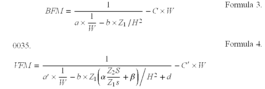
Here a, b, c, d, a′, b′, C′, α and β are constants determined by performing statistical processing on samples extracted randomly from the parent group of subjects; Z1 (Ω) is the value of the impedance measured between one hand and foot using a signal of the first frequency; Z1S (Ω) is the value of the impedance of the thoracic region measured using a signal of the first frequency; Z1S=A1−(Z1h+Z1f)/2; Z1h is the impedance between the hands; Z1f is the impedance between the feet; and Z2S (Ω) is the value of the impedance of the thoracic region measured using a signal of the second frequency. Visceral Fat Mass (VFM), Body Fat Ratio (% Fat) and Visceral-to-Subcutaneous Ratio (V/S Ratio) are determined by the following calculations.
A V/S ratio greater then 0.5 indicates visceral-type obesity; a V/S ratio less than 0.5 indicates the subcutaneous-type.
(3) VFM is calculated based on the results of measuring the impedance using signals of both the first and second frequency. (The standard measurement is made between both hands and both feet.)
The estimation scheme is identical to that used above in (1) and (2); however, the method of calculating Z1, Z1S and Z2S differs as follows.
Calculation of Z1
Z1W: Impedance between both hands and both feet (measured using a signal of the first frequency)
Z1h: Impedance between the hands (measured using a signal of the first frequency)
Z1f: Impedance between the feet (measured using a signal of the first frequency)
Calculation of Z1S
Calculation of Z2S
Z2W: Impedance between both hands and both feet (measured using a signal of the second frequency)
Z2h: Impedance between the hands (measured using a signal of the second frequency)
Z2f: Impedance between the feet (measured using a signal of the second frequency)
The operation of this system will now be described with reference to the flowcharts in FIGS. 13, 14 and 15. The impedance as measured between one hand and one foot shall be used as a standard.
When power supply switch 14 is turned on, various preparatory procedures are performed. The RAM is initialized, the circuit elements and display elements are checked, and so on (Step, hereafter ST 1). The user enters, via input unit 15, his or her characteristic physical data, including height, weight, age, sex, and waist-to-hip ratio, as well as the data and time (ST 2). Until all the data have been input, the device stands by (ST 2 and ST 3). When data entry is completed, the CPU determines whether the foot electrode unit is connected (ST 4) by determining whether there is a connection detection signal from connector 66 or 67 in the circuit shown in FIGS. 4 and 5.
If the determination in ST 4 was “no”, a message will be displayed on display 16 to the effect that the foot electrodes must be connected, to inform the user (ST 5). If the determination in ST 4 was “yes”, frequency f1 is selected, voltage switch unit 32 b and signal generator 21 a are chosen, and the voltage selection flag is set (ST 6). Electrode switch unit 32 a is set to the mode for measuring impedance between the right hand and foot, and the identification code is set to select right hand and right foot (ST 7).
When the setting of the switches is completed, the device stands by until the start switch on input unit 15 is actuated (ST 8). After the switches have been set, a command such as “Actuate start switch” can appear on display 16 to encourage the user to operate the key. When the start switch is turned on, there is a time delay of several seconds (ST 9), after which buzzer 29 or display 16 is used to inform the user that measurement has begun (ST 10). The time delay in ST 9 after the start switch is turned on should be sufficient to allow the user to grasp grips 12 and 13 completely and correctly and to ensure proper foot placement into position guides 53 and 54.
When impedance is measured, a check is made as to whether the value obtained is stable and in the correct range (ST 11 and 12). If the value is not stable, a message such as “Hands and feet must make good contact with the electrodes” can be shown on display 16 and buzzer 29 can warn the user (ST 13). If the value measured is found to be correct and stable in ST 12, the measurement operation is executed (ST 14), and a determination is made as to whether the signal being applied has the first frequency (ST 15). Since at this time the determination will be “yes”, flow proceeds to a determination as to whether the selection code for the electrode switch unit has been set to “right hand, right foot” (ST 16). Since this determination will also be “yes” at this time, the measurement result, i.e., the impedance value which was measured, will be stored in the memory area as right hand-right foot impedance ZRh−Rf (ST 17). Electrode switch unit 32 a will be switched to left hand-left foot mode, and the identification code will be changed to select left hand-left foot (ST 18). Program flow now returns to ST 11, and the impedance ZLh−Lf between the left hand and foot is measured in ST 11 through 14. The determination in ST 15 of whether the signal applied was of the first frequency will again be “yes”, just as it was the first time through; however, the determination in ST 16, whether the identification code for the electrode switch unit has been set to right hand-right foot, will now be “no”, since the code was changed to left hand-left foot in ST 18. Flow then proceeds to ST 19.
In ST 19, the right hand-right foot impedance value ZRh−Rf is read out of the memory area where it was stored and added to the left hand-left foot impedance value ZLh−Lf to calculate the average value Z1, which is equal to (ZRh−Rf+ZLh−Lf)/2 (ST 20). The average value Z1 is stored in the memory area (ST 21), frequency switch unit 12 b is switched to the second measurement frequency, and the frequency selection flag is reset (ST 22). The resetting of this flag indicates that the second frequency, frequency f2, has now been selected.
Once the frequency selection flag has been reset in ST 22, flow returns to ST 11, and impedance ZLh−Lf is measured between the left hand and left foot in ST 11 through 14. The determination in ST 15, whether the signal applied was of the first frequency, will be “no”, so program flow passes to ST 23, which queries whether the identification code for the electrode switch unit is set to left hand-left foot. The answer here is “yes”, so the impedance value ZLh−Lf which was measured is stored at this time in the memory area (ST 24). Flow now reverts to the right hand-right foot measurements mode, changes the identification code back to the code to select right hand-right foot (ST 25), and returns to ST 11.
In ST 11 through 14, the impedance ZRh−Rf between right hand and right foot is measured by applying a signal of frequency f2. The determination in ST 15 and 23 will be “no”, so flow proceeds to ST 26, which queries whether the code is that for right hand-right foot. When the result is “yes”, the impedance value ZLh−Lf which was previously stored in the memory area (ST 27) is read out. The right hand-right foot vale ZRh−Rf and the left hand-left foot value ZLh−Lf are used to calculate the average value Z2b using Z2b=(ZRh−Rf+ZLh−Lf)/2 (ST 28). This average value Z2b is stored in the memory area (ST 29), electrode switch unit 32 a is switched to the hand-to-hand mode, the identification code is changed to select hand-to-hand (ST 30), and returns to ST 11.
ST 11 through 14 measure the impedance Z2h between the hands. Since the determinations in ST 15, 23 and 26 are all “no”, flow proceeds to ST 31, where the process determines if the identification code selects hand-to-hand. The answer is “yes”, so the hand-to-hand impedance value Z2h which was measured is stored in the memory area (ST 32). Electrode switch unit 32 a is switched to foot-to-foot measurement mode, the identification code is changed to select foot-to-foot (ST 33), and flow returns to ST 11.
ST 11 through 14 measure the impedance Z2f between the feet. Since the determinations in ST 15, 23, 26 and 31 are all “no”, flow proceeds to ST 34, where the average hand-foot impedance value Z2b and the hand-to-hand impedance value Z2h are read from the memory. From impedance values Z2b and Z2h and the foot-to-foot impedance value Z2f, the impedance Z2S of the thoracic region is calculated using Z2S=Z2b−(Z2h+Z2f)/2 (ST 25). The personal data, including weight, height, and so on, are read out of the memory area (ST 36). The personal data and the calculated value Z2S are substituted in the formula to estimate VFM, and the VFM is calculated (ST 37).
The average value Z1 for hand-foot impedance as measured with a signal of the first frequency is read out of the memory area (ST 38). The personal data and value Z1 are substituted in the formula to estimate body fat ratio, and the body fat ratio is calculated (ST 39). Body fat mass is calculated using the formula BFM−W×% Fat/100 (where W is weight) (ST 40). Subcutaneous fat mass is calculated using the formula SFM=BFM−VFM, and the visceral-to-subcutaneous ratio is obtained by V/S=VFM/SFM (ST 41).
A determination is made as to whether the V/S ratio is less than 0.5 (ST 42) If V/S is less than 0.5, a determination is made that the obesity is of the subcutaneous type (ST 42). If the ratio exceeds 0.5, the obesity is judged to be of the visceral type (ST 43). The fact that all measurements and calculations have been completed is conveyed by display 16 and buzzer 29 (ST 45). The results of the calculations and advisory data are displayed on display 16 or output to the exterior via a communication device (ST 46).
The following explains the operation of an embodiment in which the standard measurement mode is between both hands and feet, with reference to the flowcharts shown in FIGS. 16, 17 and 18.
The initial processing performed when power supply switch 14 is actuated include ST 51 through 56, and are identical to ST 1 through 6 of measuring the impedance across one hand and foot. In ST 57 electrode switch unit 32 a is set to measurement mode for both hands-both feet, and the identification code is set to both hands-both feet. When the setting of the switches has been completed, the device stands by until the start switch on input unit 15 is actuated (ST 58). When the start switch is turned on, there is a time delay identical to that experienced when measuring impedance between one hand and foot (ST 59). The user is informed that measurement has begun (ST 60), and the impedance Z1W between both hands and both feet is measured through the processing performed in ST 61 through 64.
A determination is made as to whether the signal applied was of the first frequency (ST 65). Since initially this determination will be “yes”, flow proceeds to the determination of whether the selection code for the electrode switch unit is set for both hands-both feet (ST 66). This determination is also “yes” at this time, so the impedance Z1W between both hands and feet is stored in the memory area (ST 67). Electrode switch unit 32 a is switched to hand-to-hand mode, and the identification code is changed to that which selects hand-to-hand (ST 68). Flow returns to ST 11, where the impedance Z1h between the hands is measured in ST 61 through 64. The determination in ST 65, whether the signal applied is of the first frequency, is still “yes”, but the determination is ST 66, whether the identification code for the electrode switch unit is set to select both hands-both feet, is now “no”, since the code was changed to select hand-to-hand in ST 68, so flow proceeds to ST 69. The determination in ST 69, whether the selection code is set to hand-to-hand, is “yes”, so the measurement result Z1W is stored in the memory area (ST 70). The electrode switch unit is changed to foot-to-foot mode (ST 80), the identification code is changed to select foot-to-foot, and flow returns to ST 61.
In ST 61 through 64, the impedance Zf between the feet is measured. The determinations in ST 65, 66 and 69 are all “no”, so flow proceeds to ST 71. In this step, impedance Z1W, measured between both hands and feet, and impedance Z1h, measured between the hands, are read out of the memory area where they have been stored. Using Z1W, Z1h, and impedance Z1f, measured between the feet, Z1 is obtained by solving Z=Z1W+(Z1h+Z1f)/4, and Z1S is obtained by solving Z1S=Z1W−(Z1h+Z1f)/4 (ST 72). Z1 and Z1S are stored in the memory area (ST 73), the frequency switch unit is switched to select the second measurement frequency, frequency f2, and the frequency selection flag is reset (ST 74). The electrode switch unit is changed to hand-to-hand measurement mode, the identification code is changed to select hand-to-hand measurement mode (ST 68), and flow returns to ST 61.
In ST 61 through 64, the impedance Z2h between the hands is measured using a signal of frequency f2. The determinations in ST 65 and 75 are both “no”, so flow proceeds to ST 78, which required a determination as to whether the code is set to select hand-to-hand impedance. The answer is “yes”, so the measurement result, i.e., impedance Z2h measured between the hands, is stored in the memory area (ST 79). The electrode switch unit is changed to foot-to-foot measurement mode, the identification code is changed to select foot-to-foot (ST 80), and flow returns to ST 61.
In ST 61 through 64, the impedance Z2f between the feet is measured. The determination in ST 65, 75 and 78 are all “no”, so flow proceeds to ST 81 where impedance Z2W measured between both hands and feet, and impedance Z2h measured between the hands, are read out of the memory area where they have been stored. Using Z2W, Z2h, and impedance Z2f, measured between the feet, the impedance Z2S of the thoracic region can be calculated by solving Z2S=Z2W−(Z2h+Z2f)/4 (ST 82). The personal data, including weight, height, and so on, are read out of the memory area (ST 83). The personal data and the calculated value Z2S are substituted in the formula to estimate VFM, and the VFM is calculated (ST 84). In the same way, BFM is calculated using the BFM estimation scheme (ST 85). Weight W is read out, and the body fat ratio is calculated by solving % Fat=(BFM/W)×100 (ST 86). The subcutaneous fat mass is calculated by SFM=BFM−VFM, and the visceral-to-subcutaneous ratio is obtained by V/S=VFM/SFM (ST 87).
Just as in ST 42 through 46 when measuring one hand and foot, a determination is made as to whether V/S is less than 0.5 (ST 88). If it is, the obesity is judged to be of the subcutaneous type (ST 90). If V/S exceeds 0.5, it is judged to be of the visceral type (ST 89). The fact that all measurements and calculations have been completed is conveyed by display 16 and buzzer 29 (ST 91). The results of the calculations and advisory data are displayed on display 16 or output via a communication device (ST 92).
It is well known that the ratio of body fat and body fat mass calculated using the impedance measured between parts of the body with standard voltage measurements, as described above, and the W/H (waist-to-hip) ratio can be used to estimate the ratio of visceral-to-subcutaneous, fat mass, the visceral fat mass, and other useful values. This is discussed in further detail herein.
The impedance across the various parts of the human body is represented in an equivalent fashion in FIG. 19. The impedance ZfS (=ZfS1, =ZfS2), which is found within the impedance Zf measured between the feet, contains data concerning the hips (H). The impedance ZS measured in the center of the thoracic region contains data concerning the waist.
The arms and legs generally develop in balance with each other. Both the arms and legs of a large-boned person will be thick. Similarly, a muscular person will generally have arms and legs which are equally developed. This makes it possible to extract ZfS by subtracting Zh from Zf and dividing. It follows, then, that
α1, β1 and γ1 are constants
From the above, W/H is calculated. 
Here f (height and weight data) is revised to correspond to personal data concerning height and weight, and α2 and β2 are constants.
A partial circuit diagram for the device of this embodiment, which estimates the W/H ratio using the impedance values measured and uses the various impedance values and the W/H ratio to estimate VFM, the visceral-to-subcutaneous fat ratio and other values, is shown in FIG. 20. Unlike the device pictured in FIGS. 4 and 5, the device of this embodiment has only one frequency switch unit, 32, which corresponds to unit 32 a in the earlier embodiment. The rest of this device, including the circuitry beyond differential amplifier 22, which is not shown, is identical to the previous embodiment, and hence a detailed explanation is omitted.
The operation of this embodiment of the device will be explained with reference to the flowchart shown in FIGS. 21, 22 and 23.
The initial power-up processing in ST 101 through 105 is the same as that in ST 1 through 5 in FIGS. 13 through 15. After ST 104 verifies that good contact is being made with the foot electrodes, electrode switch 32 is set to measurement mode for right hand-right foot, and the identification code is set to right hand-right foot (ST 106).
When the setting of the switches is completed, the device stands by until the start switch on input unit 15 is actuated (ST 107). When this switch is turned on, the time delay processing is performed (ST 108), and the user is informed that measurement has begun (ST 109). The impedance ZRh−Rf between right hand and foot is measured in ST 110 through 113.
Next, the CPU determines whether the selection code for the electrode switch unit is set for right hand-right foot (ST 114). Since this determination will be “yes” at this time, the measurement result, i.e., the impedance value which was measured, will be stored in the memory area as right hand-right foot impedance ZRh−Rf (ST 115), electrode switch unit 32 will be switched to left hand-left foot mode, and the identification code will be changed to select left hand-left foot (ST 116). Processing flow returns to ST 110, and the impedance ZLh−Lf between the left hand and foot is measured in ST 110 through 113. The determination in ST 114, whether the selection code for the electrode switch unit is set for right hand-right foot, will now be “no”, since the code was changed to left hand-left foot in ST 116, so flow proceeds to ST 117.
ST 117 makes a determination whether the selection code is set for left hand-left foot. Since the answer is now “yes”, the impedance ZRh−Rf between right hand and foot is read out of the memory area where it was stored (ST 118). Along with impedance ZLh−Lf between left hand and foot, this value is used to calculate the average value Zb by solving Zb=(ZRh−Rf+ZLh−Lf)/2 (ST 119). This average value Zb is stored in the memory area (ST 120), the electrode switch unit is switched to hand-to-hand mode, the identification code is changed to select hand-to-hand (ST 121), and flow returns to ST 110.
The impedance Zh between the hands is measured in ST 110 to 113. Since the determination in ST 114 and 117 will be “no”, flow proceeds to ST 122 which determines whether the selection code indicates hand-to-hand. Since the answer will be “yes”, the measurement result, i.e., the impedance Zh measured between the hands, is stored in the memory area (ST 123). The electrode switch unit is switched to foot-to-foot measurement mode, the identification code is switched to foot-to-foot (ST 124), and program flow returns to ST 110.
The impedance Zf between the feet is measured in ST 110 to 113. Since the determinations in ST 114, 117 and 122 will all be “no”, flow moves to ST 125, where the average impedance Zb between hands and feet and the impedance Zh between the hands is read out of the memory area. From impedance values Zb, Zh and Zf, the impedance between the feet, the impedance ZS of the thoracic region is obtained by solving ZS=Zb−(Zh+Zf)/2 (ST 126). Next, the personal data including weight and height are read out of the memory area (ST 127). By substituting these personal data and ZS, Zh and Zf in the formula to estimate the W/H ratio, the ratio (ST 128) is obtained. And by substituting the average impedance Zb between hand and foot and the personal data in the formulas to estimate body fat ratio and body fat mass, % Fat and BFM (ST 129) are calculated. The personal data, W/H ratio, body fat ratio and BFM yield the following. 
Here α and β are constants. SFM and BFM are calculated by SFM−BFM/(1+V/S) and VFM=BFM−SFM. The visceral-to-subcutaneous ratio V/S, the subcutaneous fat mass SFM and the visceral fat mass VFM are calculated (ST 130).
Just as in ST 42 through 46 in FIGS. 13 through 15, a determination is made as to whether the V/S ratio is less than 0.5 (ST 131). If it is less, a determination is made that the obesity is of the subcutaneous type (ST 133). If the ratio exceeds 0.5, the obesity is judged to be of the visceral type (ST 132). When all measurements and calculations have been completed, display 16 and buzzer 29 indicate completion (ST 134). The results of the calculations and advisory data are displayed on display 16 or output to the exterior via a communication device (ST 135).
Although only a few embodiments have been described in detail above, those having ordinary skill in the art will certainly understand that many modifications are possible in the preferred embodiment without departing from the teachings thereof.
All such modifications are intended to be encompassed within the following claims.
Claims (11)
1. A body fat detecting device, comprising:
a first pair of electrodes and a second pair of electrodes;
a main unit having first and second body contact elements at respective ends of the main unit, each of said first and second body contact elements including thereon an electrode from each of said first pair of electrodes and said second pair of electrodes;
a signal generator configured to supply a high frequency signal to said first pair of electrodes;
a determination device which determines an impedance between said second pair of electrodes;
a calculating device which calculates fat data based on said impedance; and
a display for displaying results calculated by said calculating device and located on said main unit.
2. A body fat detecting device according to claim 1 further comprising means for allowing entry of individual data about a subject, and wherein said calculating device is responsive to said individual data for calculating a fat mass.
3. A body fat detecting device according to claim 1 wherein said signal generator is configured to supply a first high frequency current, wherein said first high frequency current travels primarily towards external tissue, and a second high frequency current, wherein said second high frequency current travels primarily towards internal tissues.
4. A body fat detecting device according to claim 3 wherein said calculating device calculates a ratio between visceral fat mass and subcutaneous fat mass and uses said ratio to determine a type of fatness of the subject.
5. A body fat detecting device, comprising:
a first pair of electrodes and a second pair of electrodes;
a main unit having first and second body contact elements at respective ends thereof, each of said first and second body contact elements comprising an electrode from each of said first pair of electrodes and said second pair of electrodes;
a signal generator configured to supply a high frequency signal to said first pair of electrodes;
a determination device which determines an impedance between said second pair of electrodes;
verification means for verifying if a value of said impedance is in a proper range and is stable;
a calculating device which calculates fat data based on said impedance if said verification means verifies said value of said impedance is in a proper range and is stable; and
a display for displaying results calculated by said calculating device and located on said main unit.
6. A body fat detecting device according to claim 5, wherein said body contact elements comprise top units at top ends of said main unit and bottom units at bottom ends of said main unit.
7. A body fat detecting device according to claim 5, wherein said means for determining an impedance comprises means for providing a time delay processing after a start key on said main unit is initiated in order to ensure that said body contact elements are properly contacted.
8. A body fat detecting device according to claim 7, further comprising means for allowing entry of individual data about a subject, and wherein said calculating means is responsive to said individual data for calculating a fat mass.
9. A body fat detecting device according to claim 7, wherein said signal generator comprises first means for supplying a first high frequency current, wherein said first high frequency current travels primarily towards external tissue, and second means for supplying a second high frequency current, wherein said second high frequency current travels primarily towards internal tissue.
10. A body fat detecting device according to claim 7, wherein said calculating device calculates a ratio between visceral fat mass and subcutaneous fat mass and uses said ratio to determine a type of obesity.
11. A body fat detecting device, comprising:
a first pair of electrodes and a second pair of electrodes;
a main unit having first and second body contact elements at respective ends thereof, each of said first and second body contact elements comprising an electrode from each of said first pair of electrodes and said second pair of electrodes;
a signal generator configured to supply a high frequency signal to said first pair of electrodes;
a determination device which determines an impedance between said second pair of electrodes;
verification means for verifying if a value of said impedance is in a proper range and is stable in order to ensure that said first and second body contact elements are properly engaged;
a calculating device which calculates a fat mass based on said impedance if said verification means verifies said value of said impedance is in a proper range and is stable; and
a display for displaying results calculated by said calculating device and located on said main unit.
Applications Claiming Priority (6)
| Application Number | Priority Date | Filing Date | Title |
|---|---|---|---|
| JP5-200688 | 1993-08-12 | ||
| JP20068893A JP3182991B2 (en) | 1993-08-12 | 1993-08-12 | Health management guideline advice device |
| JP5-213954 | 1993-08-19 | ||
| JP21395493A JP3211117B2 (en) | 1993-08-30 | 1993-08-30 | Health management guideline advice device |
| JP5-299089 | 1993-09-14 | ||
| JP22908993A JP3211118B2 (en) | 1993-09-14 | 1993-09-14 | Health management guideline advice device |
Publications (1)
| Publication Number | Publication Date |
|---|---|
| US6321112B1 true US6321112B1 (en) | 2001-11-20 |
Family
ID=27327850
Family Applications (4)
| Application Number | Title | Priority Date | Filing Date |
|---|---|---|---|
| US08/288,719 Expired - Lifetime US5579782A (en) | 1993-08-12 | 1994-08-12 | Device to provide data as a guide to health management |
| US08/741,110 Expired - Lifetime US6088615A (en) | 1993-08-12 | 1996-10-30 | Device to provide data as a guide to health management |
| US09/340,940 Expired - Fee Related US6321112B1 (en) | 1993-08-12 | 1999-06-28 | Device to provide data as a guide to health management |
| US09/340,990 Expired - Fee Related US6308096B1 (en) | 1993-08-12 | 1999-06-28 | Device to provide data as a guide to health management |
Family Applications Before (2)
| Application Number | Title | Priority Date | Filing Date |
|---|---|---|---|
| US08/288,719 Expired - Lifetime US5579782A (en) | 1993-08-12 | 1994-08-12 | Device to provide data as a guide to health management |
| US08/741,110 Expired - Lifetime US6088615A (en) | 1993-08-12 | 1996-10-30 | Device to provide data as a guide to health management |
Family Applications After (1)
| Application Number | Title | Priority Date | Filing Date |
|---|---|---|---|
| US09/340,990 Expired - Fee Related US6308096B1 (en) | 1993-08-12 | 1999-06-28 | Device to provide data as a guide to health management |
Country Status (1)
| Country | Link |
|---|---|
| US (4) | US5579782A (en) |
Cited By (20)
| Publication number | Priority date | Publication date | Assignee | Title |
|---|---|---|---|---|
| US20020151803A1 (en) * | 2001-04-11 | 2002-10-17 | Tanita Corporation | Apparatus for measuring visceral fat |
| US20030046009A1 (en) * | 2001-08-29 | 2003-03-06 | Tanita Corporation | Living body data management system with function of displaying growth process graph |
| US20030135336A1 (en) * | 2001-12-17 | 2003-07-17 | Masahiro Inoue | Body data measuring apparatus |
| US6621013B2 (en) * | 2001-05-29 | 2003-09-16 | Tanita Corporation | Living body measuring device having function for determining measured subject |
| US6643542B1 (en) * | 1999-08-27 | 2003-11-04 | Yamato Scale Co., Ltd. | Health condition judging/displaying device |
| US20040002662A1 (en) * | 2002-06-28 | 2004-01-01 | Kari Hjelt | Body fat monitoring system and method employing mobile terminal |
| US20040005024A1 (en) * | 2000-08-04 | 2004-01-08 | Electric Power Research Institute, Inc. | Apparatus and method for measuring current flow in an animal or human body |
| US20040035611A1 (en) * | 2000-08-04 | 2004-02-26 | Yuka Honda | Body weight managing apparatus |
| US6748264B2 (en) | 2002-02-04 | 2004-06-08 | Fook Tin Technologies Limited | Body fat analyzer with integral analog measurement electrodes |
| US20040251057A1 (en) * | 2003-06-16 | 2004-12-16 | Tanita Corporation | Bioelectrical impedance measuring device |
| US20050177060A1 (en) * | 2002-06-12 | 2005-08-11 | Iwao Yamazaki | System for displaying quantities of bone, water and/or muscle of body |
| US20050281441A1 (en) * | 2002-12-03 | 2005-12-22 | Idex Asa | Live finger detection by four-point measurement of complex impedance |
| US20100106045A1 (en) * | 2005-12-28 | 2010-04-29 | Omron Healthcare Co. Ltd. | Body composition monitor capable of accurately measuring whole-body composition and achieving facilitated manipulation |
| DE202009017800U1 (en) | 2009-06-15 | 2010-04-29 | Beurer Gmbh | Personal scale with body fat measuring device |
| EP2264411A1 (en) | 2009-06-15 | 2010-12-22 | Beurer GmbH | Weighing scale with body fat measuring device |
| CN103637800A (en) * | 2013-12-20 | 2014-03-19 | 大连大学 | Eight-section impedance model based body composition analysis method |
| US20160030758A1 (en) * | 2013-03-15 | 2016-02-04 | Koninklijke Philips N.V. | Monitor Defibrillator with Touch Screen U/I for ECG Review and Therapy |
| WO2016168873A1 (en) * | 2015-04-22 | 2016-10-27 | Falko Skrabal | Body impedance measuring device |
| CN107049240A (en) * | 2017-01-18 | 2017-08-18 | 英华达(上海)科技有限公司 | Physical age computational methods and bodily fat measurement system |
| CN110573073A (en) * | 2017-05-03 | 2019-12-13 | 华为技术有限公司 | Body fat measuring method and body fat measuring equipment |
Families Citing this family (94)
| Publication number | Priority date | Publication date | Assignee | Title |
|---|---|---|---|---|
| USRE37954E1 (en) * | 1992-09-23 | 2003-01-07 | Tanita Corporation | Method and apparatus for measuring body fat |
| US5579782A (en) * | 1993-08-12 | 1996-12-03 | Omron Corporation | Device to provide data as a guide to health management |
| JP3240401B2 (en) * | 1994-12-07 | 2001-12-17 | オムロン株式会社 | Impedance measurement device and health management guideline advice device |
| KR0161602B1 (en) * | 1995-06-24 | 1999-01-15 | 이재석 | Component analysis of human body and analytical method thereof using bioelectrical impedance analysis |
| US6243651B1 (en) * | 1996-12-17 | 2001-06-05 | Omron Corporation | Healthcare data acquisition device |
| USD424191S (en) * | 1996-12-19 | 2000-05-02 | Tefal S.A. | Body fat analyzer |
| US6393317B1 (en) * | 1997-02-24 | 2002-05-21 | Tanita Corporation | Living body impedance measuring instrument and body composition measuring instrument |
| ES2151774B1 (en) * | 1997-03-06 | 2001-07-01 | Nte Sa | APPARATUS AND PROCEDURE FOR THE MEASUREMENT OF GLOBAL AND SEGMENTAL BODY VOLUMES AND COMPOSITION IN HUMAN BEINGS. |
| US5788643A (en) * | 1997-04-22 | 1998-08-04 | Zymed Medical Instrumentation, Inc. | Process for monitoring patients with chronic congestive heart failure |
| JP3734350B2 (en) * | 1997-10-17 | 2006-01-11 | 株式会社タニタ | Body fat meter and body weight scale with body fat meter |
| CA2249036C (en) * | 1997-12-25 | 2002-03-26 | Yamato Scale Co., Ltd. | Body fat determining device |
| US6102846A (en) * | 1998-02-26 | 2000-08-15 | Eastman Kodak Company | System and method of managing a psychological state of an individual using images |
| FR2775581B1 (en) * | 1998-03-03 | 2000-05-05 | Seb Sa | APPARATUS AND METHOD FOR MEASURING BODY COMPOSITION |
| JP3098735B2 (en) * | 1998-03-05 | 2000-10-16 | 株式会社ミサキ | Separate fat meter |
| JP3743602B2 (en) * | 1998-05-25 | 2006-02-08 | 株式会社タニタ | Body fat scale with height measuring device |
| CA2291576A1 (en) * | 1998-12-03 | 2000-06-03 | William C. Levengood | Method and apparatus for detecting, recording, and analyzing spontaneously generated transient electric charge pulses in living organisms |
| JP4046883B2 (en) * | 1999-02-09 | 2008-02-13 | 株式会社タニタ | Body fat scale and health management system |
| JP3675660B2 (en) | 1999-02-22 | 2005-07-27 | 株式会社タニタ | Card type body fat scale |
| TW514510B (en) | 1999-06-11 | 2002-12-21 | Tanita Seisakusho Kk | Method and apparatus for measuring distribution of body fat |
| KR100333166B1 (en) * | 1999-07-29 | 2002-04-18 | 차기철 | Useful Apparatus and Method for Analyzing Body Composition Based on Bioelectrical Impedance |
| JP2001070273A (en) * | 1999-09-03 | 2001-03-21 | Tanita Corp | Method for measuring of biological electric impedance and body composition measuring device |
| JP3745200B2 (en) * | 1999-09-22 | 2006-02-15 | 株式会社タニタ | Measuring device for easy change of stored information |
| WO2001028416A1 (en) | 1999-09-24 | 2001-04-26 | Healthetech, Inc. | Physiological monitor and associated computation, display and communication unit |
| JP4357049B2 (en) | 1999-10-07 | 2009-11-04 | 大和製衡株式会社 | Body fat measuring device |
| JP2001104273A (en) * | 1999-10-12 | 2001-04-17 | Tanita Corp | Body fat measurement equipment attached with bath scale |
| EP1466554B1 (en) * | 1999-10-12 | 2008-01-09 | Tanita Corporation | Living body measuring apparatus |
| JP3705576B2 (en) * | 1999-10-27 | 2005-10-12 | 株式会社タニタ | Separable bioimpedance measuring device |
| JP3722678B2 (en) * | 1999-10-27 | 2005-11-30 | 株式会社タニタ | Body fat scale |
| US6292690B1 (en) | 2000-01-12 | 2001-09-18 | Measurement Specialities Inc. | Apparatus and method for measuring bioelectric impedance |
| US6538215B2 (en) * | 2000-01-13 | 2003-03-25 | Sunbeam Products, Inc. | Programmable digital scale |
| JP2001228013A (en) * | 2000-02-16 | 2001-08-24 | Tanita Corp | Biomedical measuring apparatus with weight meter |
| KR20010094598A (en) * | 2000-03-31 | 2001-11-01 | 박원희 | Device For Analysising Of Body Fat |
| US6865415B2 (en) * | 2000-04-18 | 2005-03-08 | Yamato Scale Co., Ltd. | Visceral fat determining device |
| US6482158B2 (en) | 2000-05-19 | 2002-11-19 | Healthetech, Inc. | System and method of ultrasonic mammography |
| TW515705B (en) | 2000-05-31 | 2003-01-01 | Yamato Scale Co Ltd | Visceral fat meter |
| JP3792489B2 (en) * | 2000-06-30 | 2006-07-05 | 株式会社タニタ | Bioimpedance measurement device |
| US6480736B1 (en) * | 2000-08-30 | 2002-11-12 | Tanita Corporation | Method for determining basal metabolism |
| DE20116409U1 (en) | 2000-09-30 | 2002-01-24 | Fook Tin Plastic Factory Ltd | Body fat measuring device |
| US6477409B2 (en) * | 2000-10-04 | 2002-11-05 | Tanita Corporation | Apparatus for measuring basal metabolism |
| US6472617B1 (en) * | 2000-10-06 | 2002-10-29 | Sunbeam Products, Inc. | Body fat scale with hand grips |
| TWI229596B (en) * | 2000-10-24 | 2005-03-21 | Yamato Scale Co Ltd | Measurement device for health administration |
| EP1203562A3 (en) * | 2000-10-27 | 2002-07-31 | Tanita Corporation | Method and apparatus for deriving body fat area |
| US6607387B2 (en) | 2000-10-30 | 2003-08-19 | Healthetech, Inc. | Sensor system for diagnosing dental conditions |
| KR100864415B1 (en) * | 2000-12-14 | 2008-10-20 | 가부시키가이샤 피지온 | Body impedance measuring instrument |
| JP4716586B2 (en) * | 2001-02-23 | 2011-07-06 | 大和製衡株式会社 | Visceral fat scale with sphygmomanometer |
| DE10119527A1 (en) * | 2001-04-12 | 2002-11-07 | Sitec Sensortechnik Gmbh | Method for the mobile or stationary acquisition of body function and metabolic data of a living body and device for carrying out the method |
| JP2003024303A (en) * | 2001-07-12 | 2003-01-28 | Tanita Corp | Method and device for estimating visceral fat area |
| FR2830740B1 (en) * | 2001-10-12 | 2004-07-23 | Seb Sa | BODY COMPOSITION MEASURING APPARATUS |
| JP2003135431A (en) * | 2001-10-31 | 2003-05-13 | Tanita Corp | Visceral fat estimating device |
| FR2833078B1 (en) * | 2001-11-30 | 2005-01-07 | Seb Sa | APPARATUS FOR MEASURING A BIOLOGICAL PARAMETER WITH A GRAPHICAL REPRESENTATION DISPLAY |
| JP4105472B2 (en) * | 2002-04-12 | 2008-06-25 | 株式会社フィジオン | Body composition measuring device |
| WO2004006660A1 (en) * | 2002-06-26 | 2004-01-22 | Capamo Aps | Apparatus for the registration of weight |
| KR20040003255A (en) * | 2002-07-02 | 2004-01-13 | 주식회사 메디벤처 | A management-method of and management-device of fat mass which is using mobile phone |
| US6850798B2 (en) * | 2002-10-08 | 2005-02-01 | Nestec, Ltd. | Method and apparatus for measuring body fat in animals |
| DE10256741B3 (en) * | 2002-12-05 | 2004-07-01 | Dr.Ing.H.C. F. Porsche Ag | Seat console for a vehicle seat |
| ATE485763T1 (en) * | 2002-12-14 | 2010-11-15 | Univ Tsinghua Res Inst | APPARATUS AND METHOD FOR MONITORING THE COMPOSITION OF THE BODY BY DETERMINING THE DIELECTRICITY CONSTANT AND THE IMPEDANCE OF THE BODY BASED ON DIGITAL FREQUENCY SENSING |
| US20040158166A1 (en) * | 2003-02-10 | 2004-08-12 | Levengood William C. | Method and apparatus for detecting, recording and analyzing spontaneously generated transient electric charge pulses in living organisms |
| JP2004329412A (en) * | 2003-05-02 | 2004-11-25 | Tanita Corp | Body composition measuring instrument |
| JP4099428B2 (en) * | 2003-05-21 | 2008-06-11 | 株式会社タニタ | Muscle mass estimation device |
| JP5108303B2 (en) * | 2003-08-21 | 2012-12-26 | テルシカ インコーポレーティッド | Method for reducing visceral fat by increasing the level of insulin-like growth factor (IGF-I) |
| JP4407208B2 (en) * | 2003-08-28 | 2010-02-03 | オムロンヘルスケア株式会社 | Body composition meter |
| EP2604184B1 (en) | 2003-09-12 | 2019-07-24 | Renal Research Institute, LLC | Method and apparatus for determining the circumference of a portion of a body segment |
| US20050215895A1 (en) * | 2003-11-12 | 2005-09-29 | Popp Richard L | Devices and methods for obtaining three-dimensional images of an internal body site |
| US20050247494A1 (en) * | 2004-01-20 | 2005-11-10 | Montagnino James G | Electronic scale and body fat measuring apparatus |
| US7089052B2 (en) * | 2004-02-26 | 2006-08-08 | Tanita Corporation | Method and system for estimating visceral fat area |
| JP4646614B2 (en) * | 2004-03-01 | 2011-03-09 | 株式会社タニタ | Body composition measuring device |
| CN1925786A (en) * | 2004-03-06 | 2007-03-07 | 卡里斯托医药有限公司 | Methods and devices for non-invasively measuring quantitative information of substances in living organisms |
| US7262703B2 (en) * | 2004-08-04 | 2007-08-28 | John Collins | System for generating a signal indicative of a state of a user's body |
| JP2006167073A (en) * | 2004-12-15 | 2006-06-29 | Omron Healthcare Co Ltd | Body composition meter |
| DE602006018816D1 (en) * | 2005-04-13 | 2011-01-27 | Tanita Seisakusho Kk | Apparatus and method for measuring visceral fat |
| KR100717405B1 (en) * | 2005-09-09 | 2007-05-11 | 삼성전자주식회사 | Bio signal detecting device and a method for managing health of user using the same |
| US20100292603A1 (en) * | 2005-09-21 | 2010-11-18 | Beth Israel Deaconess Medical Center, Inc. | Electrical Impedance Myography |
| US7442584B2 (en) * | 2005-11-21 | 2008-10-28 | Stmicroelectronics, Inc. | Isolated vertical power device structure with both N-doped and P-doped trenches |
| DE102005055772A1 (en) * | 2005-11-21 | 2007-05-24 | Soehnle Professional Gmbh & Co. Kg | Person weighing machine for determining e.g. body fat content of person, has handle that is held by person during usage of machine and comprises electrical and/or optical measuring sensor with electrical contact surfaces |
| JP4529913B2 (en) * | 2006-01-18 | 2010-08-25 | オムロンヘルスケア株式会社 | Body composition meter |
| US20070211355A1 (en) * | 2006-03-13 | 2007-09-13 | Arcadia Group Llc | Foot imaging device |
| DE102006038399A1 (en) * | 2006-08-15 | 2008-02-21 | Soehnle Professional Gmbh & Co. Kg | bathroom scales |
| JP2008142469A (en) * | 2006-12-13 | 2008-06-26 | Tanita Corp | Living body part size measuring instrument |
| JP5248073B2 (en) * | 2007-09-28 | 2013-07-31 | 株式会社タニタ | Biometric device |
| RU2532953C2 (en) * | 2009-02-20 | 2014-11-20 | Омрон Хэлткэа Ко., Лтд. | Biological information measuring device, method for measuring biological information and body composition measuring device |
| US8300911B1 (en) | 2009-09-10 | 2012-10-30 | General Electric Company | Methods and apparatus for measuring visceral fat mass |
| US8280138B2 (en) * | 2009-09-10 | 2012-10-02 | General Electric Company | System and method for performing bone densitometer measurements |
| US20110060247A1 (en) * | 2009-09-10 | 2011-03-10 | General Electric Company | Methods and apparatus for measuring bone lengths |
| US8295570B2 (en) * | 2009-09-10 | 2012-10-23 | General Electric Company | Methods and apparatus for measuring body circumference |
| EP2305111A1 (en) * | 2009-10-01 | 2011-04-06 | seca ag | Bioimpedance measuring device and method |
| ES2398438B1 (en) * | 2011-07-29 | 2014-03-05 | Universitat Politècnica De Catalunya | Method and apparatus for obtaining several simultaneous electrocardiogram leads |
| KR20150081735A (en) * | 2014-01-06 | 2015-07-15 | 삼성전자주식회사 | Method and Apparatus for Measuring Body Fat in Mobile Device |
| KR20160076898A (en) * | 2014-12-23 | 2016-07-01 | 삼성전자주식회사 | Apparatus for measuring a body weight and method for measuring a body weight using the same |
| EP3340874A4 (en) * | 2015-11-10 | 2019-04-17 | Impedimed Limited | Impedance measurement system |
| US20170188966A1 (en) * | 2016-01-05 | 2017-07-06 | Tosense, Inc. | Physiological monitoring system featuring floormat and wired handheld sensor |
| DE102016006329B3 (en) * | 2016-05-24 | 2018-02-01 | Robin Fox | Device arrangement for recording physical performance of a subject and method for determining physical performance of a subject |
| JP6818192B2 (en) * | 2019-07-09 | 2021-01-20 | アルケア株式会社 | Electronic device having a skin barrier function measurement circuit and a skin barrier function measurement circuit |
| US20210393157A1 (en) * | 2020-06-22 | 2021-12-23 | Aura Devices, Inc. | Systems and methods for multi-point bioimpedance measurements |
| CN115590494A (en) * | 2021-07-07 | 2023-01-13 | 华为技术有限公司(Cn) | Physiological parameter detection method and wearable device |
Citations (5)
| Publication number | Priority date | Publication date | Assignee | Title |
|---|---|---|---|---|
| US4557271A (en) | 1983-05-11 | 1985-12-10 | Stoller Kenneth P | Method and apparatus for detecting body illness, dysfunction, disease and/or pathology |
| US4895163A (en) | 1988-05-24 | 1990-01-23 | Bio Analogics, Inc. | System for body impedance data acquisition |
| US4947862A (en) | 1988-10-28 | 1990-08-14 | Danninger Medical Technology, Inc. | Body composition analyzer |
| US4949727A (en) | 1987-05-27 | 1990-08-21 | Ya-Man Ltd. | Portable physical checker |
| US5458117A (en) | 1991-10-25 | 1995-10-17 | Aspect Medical Systems, Inc. | Cerebral biopotential analysis system and method |
Family Cites Families (1)
| Publication number | Priority date | Publication date | Assignee | Title |
|---|---|---|---|---|
| US5579782A (en) * | 1993-08-12 | 1996-12-03 | Omron Corporation | Device to provide data as a guide to health management |
-
1994
- 1994-08-12 US US08/288,719 patent/US5579782A/en not_active Expired - Lifetime
-
1996
- 1996-10-30 US US08/741,110 patent/US6088615A/en not_active Expired - Lifetime
-
1999
- 1999-06-28 US US09/340,940 patent/US6321112B1/en not_active Expired - Fee Related
- 1999-06-28 US US09/340,990 patent/US6308096B1/en not_active Expired - Fee Related
Patent Citations (5)
| Publication number | Priority date | Publication date | Assignee | Title |
|---|---|---|---|---|
| US4557271A (en) | 1983-05-11 | 1985-12-10 | Stoller Kenneth P | Method and apparatus for detecting body illness, dysfunction, disease and/or pathology |
| US4949727A (en) | 1987-05-27 | 1990-08-21 | Ya-Man Ltd. | Portable physical checker |
| US4895163A (en) | 1988-05-24 | 1990-01-23 | Bio Analogics, Inc. | System for body impedance data acquisition |
| US4947862A (en) | 1988-10-28 | 1990-08-14 | Danninger Medical Technology, Inc. | Body composition analyzer |
| US5458117A (en) | 1991-10-25 | 1995-10-17 | Aspect Medical Systems, Inc. | Cerebral biopotential analysis system and method |
Cited By (33)
| Publication number | Priority date | Publication date | Assignee | Title |
|---|---|---|---|---|
| US6643542B1 (en) * | 1999-08-27 | 2003-11-04 | Yamato Scale Co., Ltd. | Health condition judging/displaying device |
| US6865410B2 (en) * | 2000-08-04 | 2005-03-08 | Electric Power Research Institute, Inc. | Apparatus and method for measuring current flow in an animal or human body |
| US6963035B2 (en) | 2000-08-04 | 2005-11-08 | Tanita Corporation | Body weight managing apparatus |
| US20040005024A1 (en) * | 2000-08-04 | 2004-01-08 | Electric Power Research Institute, Inc. | Apparatus and method for measuring current flow in an animal or human body |
| US20040035611A1 (en) * | 2000-08-04 | 2004-02-26 | Yuka Honda | Body weight managing apparatus |
| US6752760B2 (en) * | 2001-04-11 | 2004-06-22 | Tanita Corporation | Apparatus for measuring visceral fat |
| US20020151803A1 (en) * | 2001-04-11 | 2002-10-17 | Tanita Corporation | Apparatus for measuring visceral fat |
| US6621013B2 (en) * | 2001-05-29 | 2003-09-16 | Tanita Corporation | Living body measuring device having function for determining measured subject |
| US6853949B2 (en) * | 2001-08-29 | 2005-02-08 | Tanita Corporation | Living body data management system with function of displaying growth process graph |
| US20030046009A1 (en) * | 2001-08-29 | 2003-03-06 | Tanita Corporation | Living body data management system with function of displaying growth process graph |
| US20030135336A1 (en) * | 2001-12-17 | 2003-07-17 | Masahiro Inoue | Body data measuring apparatus |
| US6748264B2 (en) | 2002-02-04 | 2004-06-08 | Fook Tin Technologies Limited | Body fat analyzer with integral analog measurement electrodes |
| US20050177060A1 (en) * | 2002-06-12 | 2005-08-11 | Iwao Yamazaki | System for displaying quantities of bone, water and/or muscle of body |
| US7764991B2 (en) * | 2002-06-12 | 2010-07-27 | Ya-Man Ltd. | System for displaying quantities of bone, water and/or muscle of body |
| US20040002662A1 (en) * | 2002-06-28 | 2004-01-01 | Kari Hjelt | Body fat monitoring system and method employing mobile terminal |
| US7103407B2 (en) | 2002-06-28 | 2006-09-05 | Nokia Corporation | Body fat monitoring system and method employing mobile terminal |
| US8195285B2 (en) | 2002-12-03 | 2012-06-05 | Idex Asa | Live finger detection by four-point measurement of complex impedance |
| US20110074443A1 (en) * | 2002-12-03 | 2011-03-31 | Idex Asa | Live finger detection by four-point measurement of complex impedance |
| US20050281441A1 (en) * | 2002-12-03 | 2005-12-22 | Idex Asa | Live finger detection by four-point measurement of complex impedance |
| US7848798B2 (en) * | 2002-12-03 | 2010-12-07 | Idex Asa | Live finger detection by four-point measurement of complex impedance |
| US7060914B2 (en) * | 2003-06-16 | 2006-06-13 | Tanita Corporation | Bioelectrical impedance measuring device |
| US20040251057A1 (en) * | 2003-06-16 | 2004-12-16 | Tanita Corporation | Bioelectrical impedance measuring device |
| US8666485B2 (en) * | 2005-12-28 | 2014-03-04 | Omron Healthcare Co., Ltd. | Body composition monitor capable of accurately measuring whole-body composition and achieving facilitated manipulation |
| US20100106045A1 (en) * | 2005-12-28 | 2010-04-29 | Omron Healthcare Co. Ltd. | Body composition monitor capable of accurately measuring whole-body composition and achieving facilitated manipulation |
| EP2264411A1 (en) | 2009-06-15 | 2010-12-22 | Beurer GmbH | Weighing scale with body fat measuring device |
| DE202009017800U1 (en) | 2009-06-15 | 2010-04-29 | Beurer Gmbh | Personal scale with body fat measuring device |
| US20160030758A1 (en) * | 2013-03-15 | 2016-02-04 | Koninklijke Philips N.V. | Monitor Defibrillator with Touch Screen U/I for ECG Review and Therapy |
| CN103637800A (en) * | 2013-12-20 | 2014-03-19 | 大连大学 | Eight-section impedance model based body composition analysis method |
| CN103637800B (en) * | 2013-12-20 | 2015-11-11 | 大连大学 | Based on the method for the bioelectrical impedance analysis of eight sections of impedance models |
| WO2016168873A1 (en) * | 2015-04-22 | 2016-10-27 | Falko Skrabal | Body impedance measuring device |
| US10709350B2 (en) | 2015-04-22 | 2020-07-14 | Falko Skrabal | Body impedance measuring device |
| CN107049240A (en) * | 2017-01-18 | 2017-08-18 | 英华达(上海)科技有限公司 | Physical age computational methods and bodily fat measurement system |
| CN110573073A (en) * | 2017-05-03 | 2019-12-13 | 华为技术有限公司 | Body fat measuring method and body fat measuring equipment |
Also Published As
| Publication number | Publication date |
|---|---|
| US6088615A (en) | 2000-07-11 |
| US6308096B1 (en) | 2001-10-23 |
| US5579782A (en) | 1996-12-03 |
Similar Documents
| Publication | Publication Date | Title |
|---|---|---|
| US6321112B1 (en) | Device to provide data as a guide to health management | |
| EP0715829B1 (en) | An impedance measuring device and a health management device using the same | |
| EP0835074B1 (en) | Apparatus and method for analyzing body composition using a new electrode system based on bioelectrical impedance analysis | |
| US6473642B1 (en) | Dividable type apparatus for measuring living body impedance | |
| KR100891091B1 (en) | Device for measuring body compositions | |
| EP1249205B1 (en) | Apparatus for measuring visceral fat | |
| EP0998875B1 (en) | Body fat meter with stature measuring instrument | |
| KR100864415B1 (en) | Body impedance measuring instrument | |
| KR100879787B1 (en) | Measurement method and measurement apparatus for bioelectric impedance | |
| JP4393492B2 (en) | Standing body composition measuring device | |
| JPH0779938A (en) | Health check device | |
| JPH09285455A (en) | Health management guide advising device | |
| WO1996008198A1 (en) | Apparatus and method for analyzing body composition based on bioelectrical impedance analysis | |
| JP2003290166A (en) | Device for measuring body composition under upright position type | |
| EP1902675B1 (en) | Abdominal impedance based body composition meter | |
| EP1488742B1 (en) | Biological data acquiring apparatus | |
| JP3211117B2 (en) | Health management guideline advice device | |
| US6782340B1 (en) | Body composition measuring apparatus with built-in weight meter | |
| EP1479339B1 (en) | Method and apparatus for estimation of muscle mass | |
| JP3319811B2 (en) | Body fat mass measurement device | |
| JP2001157672A (en) | Health maintenance guide-advising device |
Legal Events
| Date | Code | Title | Description |
|---|---|---|---|
| AS | Assignment |
Owner name: OMRON HEALTHCARE CO., LTD., JAPAN Free format text: ASSIGNMENT OF ASSIGNORS INTEREST;ASSIGNOR:OMRON CORPORATION;REEL/FRAME:014763/0936 Effective date: 20031029 |
|
| FPAY | Fee payment |
Year of fee payment: 4 |
|
| FPAY | Fee payment |
Year of fee payment: 8 |
|
| REMI | Maintenance fee reminder mailed | ||
| LAPS | Lapse for failure to pay maintenance fees | ||
| STCH | Information on status: patent discontinuation |
Free format text: PATENT EXPIRED DUE TO NONPAYMENT OF MAINTENANCE FEES UNDER 37 CFR 1.362 |
|
| FP | Lapsed due to failure to pay maintenance fee |
Effective date: 20131120 |