US6324029B1 - Method and system for GMR sensor reset pulse application - Google Patents
Method and system for GMR sensor reset pulse application Download PDFInfo
- Publication number
- US6324029B1 US6324029B1 US09/107,157 US10715798A US6324029B1 US 6324029 B1 US6324029 B1 US 6324029B1 US 10715798 A US10715798 A US 10715798A US 6324029 B1 US6324029 B1 US 6324029B1
- Authority
- US
- United States
- Prior art keywords
- reset pulse
- disk drive
- gmr sensor
- storage system
- magnetic disk
- Prior art date
- Legal status (The legal status is an assumption and is not a legal conclusion. Google has not performed a legal analysis and makes no representation as to the accuracy of the status listed.)
- Expired - Lifetime
Links
- 238000000034 method Methods 0.000 title claims abstract description 42
- 238000003860 storage Methods 0.000 claims abstract description 42
- 230000005291 magnetic effect Effects 0.000 claims description 93
- 230000008878 coupling Effects 0.000 claims description 15
- 238000010168 coupling process Methods 0.000 claims description 15
- 238000005859 coupling reaction Methods 0.000 claims description 15
- 230000004044 response Effects 0.000 claims description 8
- 230000003213 activating effect Effects 0.000 claims 4
- 230000005294 ferromagnetic effect Effects 0.000 description 23
- 230000005290 antiferromagnetic effect Effects 0.000 description 18
- 230000005415 magnetization Effects 0.000 description 16
- 230000008569 process Effects 0.000 description 16
- 238000010586 diagram Methods 0.000 description 7
- 230000000694 effects Effects 0.000 description 6
- 230000000903 blocking effect Effects 0.000 description 5
- 239000002885 antiferromagnetic material Substances 0.000 description 4
- 230000008859 change Effects 0.000 description 4
- 230000001360 synchronised effect Effects 0.000 description 4
- 238000010438 heat treatment Methods 0.000 description 3
- 239000000126 substance Substances 0.000 description 3
- 239000000758 substrate Substances 0.000 description 3
- 229910000531 Co alloy Inorganic materials 0.000 description 2
- 239000010941 cobalt Substances 0.000 description 2
- GUTLYIVDDKVIGB-UHFFFAOYSA-N cobalt atom Chemical compound [Co] GUTLYIVDDKVIGB-UHFFFAOYSA-N 0.000 description 2
- 239000004020 conductor Substances 0.000 description 2
- 238000000151 deposition Methods 0.000 description 2
- 238000001514 detection method Methods 0.000 description 2
- 230000004907 flux Effects 0.000 description 2
- 230000000977 initiatory effect Effects 0.000 description 2
- 238000004519 manufacturing process Methods 0.000 description 2
- 239000000463 material Substances 0.000 description 2
- 230000007704 transition Effects 0.000 description 2
- RYGMFSIKBFXOCR-UHFFFAOYSA-N Copper Chemical compound [Cu] RYGMFSIKBFXOCR-UHFFFAOYSA-N 0.000 description 1
- 229910002551 Fe-Mn Inorganic materials 0.000 description 1
- 230000005355 Hall effect Effects 0.000 description 1
- 229910003271 Ni-Fe Inorganic materials 0.000 description 1
- 230000005316 antiferromagnetic exchange Effects 0.000 description 1
- 229910017052 cobalt Inorganic materials 0.000 description 1
- 239000002772 conduction electron Substances 0.000 description 1
- 238000001816 cooling Methods 0.000 description 1
- 229910052802 copper Inorganic materials 0.000 description 1
- 239000010949 copper Substances 0.000 description 1
- 238000013500 data storage Methods 0.000 description 1
- 230000007423 decrease Effects 0.000 description 1
- 230000001419 dependent effect Effects 0.000 description 1
- 230000001939 inductive effect Effects 0.000 description 1
- 239000012212 insulator Substances 0.000 description 1
- DALUDRGQOYMVLD-UHFFFAOYSA-N iron manganese Chemical compound [Mn].[Fe] DALUDRGQOYMVLD-UHFFFAOYSA-N 0.000 description 1
- 239000000696 magnetic material Substances 0.000 description 1
- 238000012423 maintenance Methods 0.000 description 1
- ZAUUZASCMSWKGX-UHFFFAOYSA-N manganese nickel Chemical compound [Mn].[Ni] ZAUUZASCMSWKGX-UHFFFAOYSA-N 0.000 description 1
- 229910052751 metal Inorganic materials 0.000 description 1
- 239000002184 metal Substances 0.000 description 1
- 238000001208 nuclear magnetic resonance pulse sequence Methods 0.000 description 1
- 229910000889 permalloy Inorganic materials 0.000 description 1
- 125000006850 spacer group Chemical group 0.000 description 1
- 230000000472 traumatic effect Effects 0.000 description 1
Images


Classifications
-
- G—PHYSICS
- G11—INFORMATION STORAGE
- G11B—INFORMATION STORAGE BASED ON RELATIVE MOVEMENT BETWEEN RECORD CARRIER AND TRANSDUCER
- G11B5/00—Recording by magnetisation or demagnetisation of a record carrier; Reproducing by magnetic means; Record carriers therefor
- G11B5/012—Recording on, or reproducing or erasing from, magnetic disks
-
- B—PERFORMING OPERATIONS; TRANSPORTING
- B82—NANOTECHNOLOGY
- B82Y—SPECIFIC USES OR APPLICATIONS OF NANOSTRUCTURES; MEASUREMENT OR ANALYSIS OF NANOSTRUCTURES; MANUFACTURE OR TREATMENT OF NANOSTRUCTURES
- B82Y10/00—Nanotechnology for information processing, storage or transmission, e.g. quantum computing or single electron logic
-
- B—PERFORMING OPERATIONS; TRANSPORTING
- B82—NANOTECHNOLOGY
- B82Y—SPECIFIC USES OR APPLICATIONS OF NANOSTRUCTURES; MEASUREMENT OR ANALYSIS OF NANOSTRUCTURES; MANUFACTURE OR TREATMENT OF NANOSTRUCTURES
- B82Y25/00—Nanomagnetism, e.g. magnetoimpedance, anisotropic magnetoresistance, giant magnetoresistance or tunneling magnetoresistance
-
- G—PHYSICS
- G11—INFORMATION STORAGE
- G11B—INFORMATION STORAGE BASED ON RELATIVE MOVEMENT BETWEEN RECORD CARRIER AND TRANSDUCER
- G11B5/00—Recording by magnetisation or demagnetisation of a record carrier; Reproducing by magnetic means; Record carriers therefor
- G11B5/127—Structure or manufacture of heads, e.g. inductive
- G11B5/33—Structure or manufacture of flux-sensitive heads, i.e. for reproduction only; Combination of such heads with means for recording or erasing only
- G11B5/39—Structure or manufacture of flux-sensitive heads, i.e. for reproduction only; Combination of such heads with means for recording or erasing only using magneto-resistive devices or effects
- G11B5/3903—Structure or manufacture of flux-sensitive heads, i.e. for reproduction only; Combination of such heads with means for recording or erasing only using magneto-resistive devices or effects using magnetic thin film layers or their effects, the films being part of integrated structures
-
- G—PHYSICS
- G11—INFORMATION STORAGE
- G11B—INFORMATION STORAGE BASED ON RELATIVE MOVEMENT BETWEEN RECORD CARRIER AND TRANSDUCER
- G11B5/00—Recording by magnetisation or demagnetisation of a record carrier; Reproducing by magnetic means; Record carriers therefor
- G11B5/40—Protective measures on heads, e.g. against excessive temperature
-
- G—PHYSICS
- G11—INFORMATION STORAGE
- G11B—INFORMATION STORAGE BASED ON RELATIVE MOVEMENT BETWEEN RECORD CARRIER AND TRANSDUCER
- G11B19/00—Driving, starting, stopping record carriers not specifically of filamentary or web form, or of supports therefor; Control thereof; Control of operating function ; Driving both disc and head
- G11B19/02—Control of operating function, e.g. switching from recording to reproducing
- G11B19/04—Arrangements for preventing, inhibiting, or warning against double recording on the same blank or against other recording or reproducing malfunctions
-
- G—PHYSICS
- G11—INFORMATION STORAGE
- G11B—INFORMATION STORAGE BASED ON RELATIVE MOVEMENT BETWEEN RECORD CARRIER AND TRANSDUCER
- G11B5/00—Recording by magnetisation or demagnetisation of a record carrier; Reproducing by magnetic means; Record carriers therefor
- G11B2005/0002—Special dispositions or recording techniques
- G11B2005/0005—Arrangements, methods or circuits
- G11B2005/0008—Magnetic conditionning of heads, e.g. biasing
-
- G—PHYSICS
- G11—INFORMATION STORAGE
- G11B—INFORMATION STORAGE BASED ON RELATIVE MOVEMENT BETWEEN RECORD CARRIER AND TRANSDUCER
- G11B5/00—Recording by magnetisation or demagnetisation of a record carrier; Reproducing by magnetic means; Record carriers therefor
- G11B5/127—Structure or manufacture of heads, e.g. inductive
- G11B5/33—Structure or manufacture of flux-sensitive heads, i.e. for reproduction only; Combination of such heads with means for recording or erasing only
- G11B5/39—Structure or manufacture of flux-sensitive heads, i.e. for reproduction only; Combination of such heads with means for recording or erasing only using magneto-resistive devices or effects
- G11B2005/3996—Structure or manufacture of flux-sensitive heads, i.e. for reproduction only; Combination of such heads with means for recording or erasing only using magneto-resistive devices or effects large or giant magnetoresistive effects [GMR], e.g. as generated in spin-valve [SV] devices
-
- G—PHYSICS
- G11—INFORMATION STORAGE
- G11B—INFORMATION STORAGE BASED ON RELATIVE MOVEMENT BETWEEN RECORD CARRIER AND TRANSDUCER
- G11B5/00—Recording by magnetisation or demagnetisation of a record carrier; Reproducing by magnetic means; Record carriers therefor
- G11B5/48—Disposition or mounting of heads or head supports relative to record carriers ; arrangements of heads, e.g. for scanning the record carrier to increase the relative speed
- G11B5/4806—Disposition or mounting of heads or head supports relative to record carriers ; arrangements of heads, e.g. for scanning the record carrier to increase the relative speed specially adapted for disk drive assemblies, e.g. assembly prior to operation, hard or flexible disk drives
Definitions
- the present invention relates, in general, to sensors for reading magnetic flux transitions from magnetic media such as magnetic disks and magnetic tapes and, in particular, to methods and systems for resetting a GMR sensor head in particular. Still more particularly, the present invention relates to a method and system for controlling the application of a reset pulse to a GMR sensor such that existing data is not damaged or altered.
- Magnetic field sensors are in widespread commercial use in applications such as linear and rotary encoders, proximity detectors, speed and position sensors and magnetometers for sensing the earth's magnetic field.
- One common magnetic field sensor is based upon the Hall effect and is utilized to sense magnetic fields in the range of 100-10,000 Oe.
- Another common field transducer is the inductive coil which, although inexpensive, is relatively bulky and has poor low-frequency response.
- field sensors based upon anisotropic magnetoresistive (AMR) effect have been introduced. These materials show a change in electrical resistance as a function of the external magnetic field.
- Wheatstone bridge circuits made of AMR materials are used as magnetic field sensors to sense below approximately 50 Oe over a frequency range from DC to at least one megahertz.
- GMR giant magnetoresistance
- a particularly useful GMR structure is a sandwich of two essentially uncoupled ferromagnetic layers.
- the magnetization of one of the ferromagnetic layers is fixed or “pinned” in a particular direction by exchange coupling with an adjacent antiferromagnetic layer, while the magnetization of the other ferromagnetic layer is free to rotate with an externally applied field.
- This multilayer sandwich is known as a “spin valve” and exhibits a change in resistance that is proportional to the cosine of the angle between the free and pinned layers. This relationship can be exploited to create devices with an inherently linear relationship between the applied magnetic field and output voltage, which are excellent candidates for devices such as magnetic recording heads and bridge sensors.
- a GMR head designed for use in a magnetic recording device typically comprises two weakly coupled ferromagnetic layers separated by a non-magnetic metallic spacer layer in which the magnetization of one of the ferromagnetic layers is pinned.
- the pinning may be achieved by depositing the ferromagnetic layer to be pinned on an antiferromagnetic layer, such as an iron-manganese layer, to create an interfacial exchange coupling between the two layers.
- the spin structure of the antiferromagnetic layer can be aligned 10 along a desired direction (in the plane of the layer) by heating beyond the blocking temperature of the antiferromagnetic layer and cooling in the presence of a magnetic field with a predetermined direction.
- the blocking temperature is the temperature at which exchange anisotropy vanishes because the local anisotropy of the antiferromagnetic layer, which decreases with temperature, has become too small to anchor the antiferromagnetic spins to the crystallographic lattice.
- the unpinned or free ferromagnetic layer also may have the magnetization of its extensions (those portions of the free layer on either side of the central active sensing region) fixed, but in a direction perpendicular to the magnetization of the pinned layer so that only the magnetization of the central region of the free layer can rotate in the presence of an external field.
- the magnetization in the free-layer extensions may be fixed by longitudinal hard biasing or exchange coupling to an antiferromagnetic layer.
- the antiferromagnetic material is different from the antiferromagnetic material used to pin the pinned layer, and is typically nickel-manganese. This resulting structure is called a spin valve MR sensor and is referred to throughout this application as a “GMR” sensor.
- U.S. Pat. No. 5,206,590 also assigned to International Business Machines Corporation, discloses a basic GMR sensor wherein the free layer is a continuous film having a central active region and end regions. The end regions of the free layer are exchange biased by exchange coupling to one type of antiferromagnetic material, and the pinned layer is pinned by exchange coupling to a different type of antiferromagnetic material.
- GMR sensors are becoming a replacement for conventional MR sensors based upon the AMR effect. Such sensors have special potential for use as an external magnetic field sensor, such as in anti-lock braking systems and as read heads in magnetic recording systems, such as in rigid-disk drives.
- the GMR sensor which is typically fabricated by depositing an antiferromagnetic layer of Fe—Mn onto the ferromagnetic pinned layer of cobalt or permalloy, suffers from the problem that the range of blocking temperatures for this interface is relatively low, i.e., it extends only from approximately 130° C. to approximately 160° C.
- temperatures may be reached by certain thermal effects during operation of a disk drive, such as an increase in the ambient temperature inside the drive; heating of the GMR sensor due to the bias current; and rapid heating of the GMR sensor due to the head carrier contacting asperities on the disk.
- the GMR sensor can be heated by an electrical current resulting from an electrostatic discharge, often referred to as electrical overstress.
- the aforementioned cross-referenced co-pending patent application discloses a method and system for re-initializing a stack of GMR heads so that the GMR heads all have the same orientation, thereby precluding the inversion of half of the GMR heads facing oppositely from the rest. While this technique is highly desirable for providing re-initialization of GMR heads at different points during the manufacturing process, a need exists for a method and system which can re-establish a predetermined magnetic orientation of a GMR sensor in a magnetic disk drive storage system while protecting data stored therein during operation of that disk drive system.
- a method and system are disclosed for controlling the application of a reset voltage pulse to a GMR sensor in a direct-access storage device (DASD), such that existing data is not damaged or altered.
- DASD direct-access storage device
- Each sensor is positioned or parked at a location reserved for reset pulse application, where no valid data is stored.
- a complex interrelated set of commands is then initiated, and upon completion of the entire set of interrelated commands, a reset pulse is applied to the GMR sensor. Any variation or interruption in the complex interrelated set of commands will result in a disarming of the reset pulse circuitry, effectively preventing an accidental or inadvertent application of the GMR reset pulse.
- a group of GMR sensors each may be tracked to a reserve track, forming a reserve cylinder. Servo marks on the reserve track are sensed by a selected sensor and utilized to ensure no valid data is present. An alternate sensor is then temporarily selected, and a reset pulse is applied, timed to avoid occurrence over a servo mark.
- FIG. 1 is a block diagram of a digital data processing system which may be utilized to implement one embodiment of the present invention
- FIG. 2 is a high-level block diagram of the arm electronics and head and disk assembly of the digital data processing system of FIG. 1;
- FIG. 3 is a cross-sectional plan view of a GMR sensor which may be utilized to implement the method and system of the present invention
- FIG. 4 is a high-level logic flow chart illustrating an asynchronous command-driven reset control function in accordance with one embodiment of the present invention
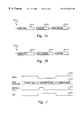
- FIGS. 5 a and 5 b are timing diagrams illustrating the timing of the asynchronous command-driven reset control function depicted in FIG. 4;
- FIG. 6 is a high-level logic flow chart illustrating a synchronous “flying” reset control function in accordance with a second embodiment of the present invention.
- FIG. 7 is a timing diagram illustrating the synchronous “flying” reset control function of the present invention.
- FIG. 1 generally illustrates the implementation of a digital data processing system 100 .
- System 100 includes a host 102 which is typically a computing system such as an S/390, AS/400 or a similar type well-known to those skilled in the computer arts.
- Host 102 preferably is coupled to direct-access storage device 106 (DASD) via input/output channel 104 .
- DASD direct-access storage device
- Channel 104 may perform various functions such as coordinating, receiving and sending data and commands to and from host 102 , or other typical input/output interface functions well-known in the art.
- DASD 106 comprises drive electronics 108 , arm electronics 110 and a head and disk assembly 112 .
- Drive electronics 108 interface and cooperate with arm electronics 110 to control the physical movements of the components DASD 106 and the transfer of data and commands to and from the head and disk assembly 112 .
- Head and disk assembly 112 is shown in greater detail in FIG. 2 .
- data and commands are sent via arm electronics (AE) 110 which, in turn, communicates with head and disk assembly 112 , including multiple GMR sensors 118 ( a-f ), a head-positioning motor 120 , and a spindle motor 116 .
- AE arm electronics
- head and disk assembly 112 including multiple GMR sensors 118 ( a-f ), a head-positioning motor 120 , and a spindle motor 116 .
- Each GMR sensor is individually attached to an actuating arm 117 , and more than one sensor may be used to read or write to a given disk.
- headpositioning motor 120 and spindle motor 116 may receive information directly from drive electronics 108 . In either event, information received by the head and disk assembly is utilized to move an actuating arm having a designated sensor 118 to a position over a storage medium 114 .
- Spindle motor 116 may be engaged to rotate the disk to cooperate in locating the sensor to a desired location.
- FIG. 3 depicts a cross-sectional plan view of a GMR sensor which may be utilized to implement the method and system of the present invention.
- FIG. 3 depicts a plan view of the air-bearing surface of a substrate 301 containing GMR sensor 300 .
- the substrate's air-bearing surface normally rides on a cushion of air, which separates it from a magnetic data storage medium, such as a disk or tape.
- Sensor 300 includes a plurality of substantially parallel layers, including an antiferromagnetic layer 302 , a ferromagnetic pin layer 303 , a conductive layer 304 , and a ferromagnetic free layer 305 .
- Sensor 300 also preferably includes hard biased layer 315 and 316 , the operation of which will be discussed in detail herein.
- Sensor 300 is preferably deposited upon an insulator 107 which lies atop substrate 301 . Adjacent layers preferably lie in direct atomic contact with each other.
- Antiferromagnetic layer 302 preferably comprises a type and thickness of antiferromagnetic substance suitable for use as a pinned layer in GMR sensors, e.g., a 400 Angstrom layer of NiO.
- the ferromagnetic pinned layer 303 preferably comprises a type and thickness of ferromagnetic substance suitable for use in GMR sensors, e.g., a 10-40 Angstrom layer of Co.
- Conductor layer 304 preferably comprises a type and thickness of conductive substance suitable for use in a GMR sensor, such as a 20-30 Angstrom layer of copper.
- the ferromagnetic free layer 305 preferably comprises a 30-150 Angstrom layer of Ni—Fe.
- Hard-biased layers 315 and 316 provide the free layer 305 with a desired quiescent magnetization.
- Hard-biased layers 315 and 316 preferably comprise a magnetic material with a high coercivity, such as CoPtCr.
- GMR sensor 300 While the foregoing description of GMR sensor 300 is particularly detailed, those having ordinary skill in the art will appreciate that the method and system of the present invention may be applied to various different sensor arrangements in addition to the present example.
- Sensor 300 preferably exhibits a predefined magnetization. Magnetization of sensor 300 , including the ferromagnetic layers 303 and 305 and antiferromagnetic layer 302 is generally magnetized, prior to initial operation, during fabrication or assembly. Additionally, sensor 300 may be magnetized after some period of operating sensor 300 if sensor 300 loses its magnetic orientation due to a traumatic high-temperature event, such as electrostatic discharge.
- antiferromagnetic layer 302 has a magnetic orientation in a direction indicated at reference numeral 310 .
- conventional directional shorthand is utilized in the present description wherein an encircled dot indicates a direction coming out of the page, and an encircled x indicates a direction going into a page.
- Neighboring ferromagnetic pinned layer 303 has a magnetic moment pinned in a parallel direction 311 due to antiferromagnetic exchange coupling between layers 302 and 303 .
- free layer 305 has a magnetic moment that freely responds to external magnetic fields, such as those present in a magnetic storage medium. Free layer 305 responds to an external magnetic field by changing its magnetic moment, which in turn changes the resistance of GMR sensor 300 . In the absence of any other magnetic fields, free layer 305 orients itself in a direction 313 , which is oriented 90° to the directions indicated at reference numerals 310 and 311 . This quiescent magnetization direction is due to biasing of free layer 305 by hard biased layers 315 and 316 .
- GMR sensor 300 also may include various accessories to direct electrical current and magnetic fields through GMR sensor 300 .
- a small but constant sense current for example, is preferably directed through GMR sensor 300 to provide a source of scattering electrons for operation of GMR sensor 300 according to the GMR effect.
- a relatively large current pulse or waveform may be directed through GMR sensor 300 to establish the magnetization direction of GMR sensor 300 in accordance with the method and system of the present invention.
- GMR sensor 300 is preferably attached to a pair of complimentary conductive leads 308 and 309 in order to facilitate electrical connection to a sense current source 312 .
- Conductive leads 308 and 309 also facilitate electrical connection to a pulse current source 323 .
- Conductive leads 308 and 309 preferably comprise a 500 Angstrom layer of Ta with a 50 Angstrom underlayer of Cr, or other suitable thickness and type of conductive material. The attachment of leads to magnetoresistive sensors is a well-known technique familiar to those having ordinary skill in the art and will not be discussed herein.
- a reset pulse which may be applied to GMR sensor 300 in order to re-establish a predetermined magnetic orientation thereof is typically comprised of an electrical current pulse utilized to heat the antiferromagnetic layer beyond its blocking temperature and a magnetic field which is simultaneously applied in order to orient the antiferromagnetic layer in accordance with the well-known right-hand rule of electromagnetics.
- the pulse of current preferably lasts sufficiently long to remove any magnetic orientation of the antiferromagnetic layer and also to reorient the layers in accordance with the magnetic field created by the flowing current.
- This reset pulse has the effect of pinning the magnetization directions of the ferromagnetic pinned layer 303 . This will occur as a result of the strong exchange coupling between the antiferromagnetic-ferromagnetic pair 302 and 303 .
- a reset pulse not be applied to a GMR sensor while the GMR sensor is proximate to valid customer data.
- the reset pulse voltage typically applied to raise the heat of the GMR sensor is generally close to the damage point of a GMR sensor, a reset pulse must never be inadvertently applied. Consequently, a method and system are required for re-establishing a predetermined a magnetic orientation of a GMR sensor in a magnetic disk drive storage system while protecting the data stored therein.
- Block 402 illustrates a determination of whether or not a reset pulse is required. Such a determination may be made as a result of erroneous data readings or, periodically, in accordance with a set maintenance schedule. In the event a reset pulse is not required, the process merely iterates until such time as a reset pulse may be required.
- the sensor in the event a reset pulse is required, the sensor is parked or placed at a designated location wherein no valid customer data is located.
- the magnitude of the reset pulse is such that valid customer data may be corrupted by the application of a reset pulse while the sensor is located proximate to stored data.
- an asynchronous GMR reset pulse sequence must consist of a complex, interrelated set of three serial port operations performed in a specified order.
- the first operation is the arming of the GMR reset pulse circuit.
- a valid head address must be selected.
- a valid head address comprises a head address which identifies an actual head within the system.
- Block 408 illustrates a determination of whether or not the next operation which occurs is a GMR reset pulse trigger. If so, the process passes to block 410 which initiates the GMR reset pulse.
- Block 412 illustrates the immediate disarming of the GMR reset pulse circuit.
- the process also passes to block 412 which depicts the disarming of the GMR reset pulse circuit. In either event, the process then passes to block 414 and returns.
- the asynchronous command-driven reset control function described therein allows the user to apply a GMR reset pulse whenever the head is not flying over valid data, is parked distant from valid data and when the pulse does not need to be applied synchronously consistent with the revolution of the magnetic disk.
- FIGS. 5 a and 5 b a series of timing diagrams are depicted illustrating the timing of the asynchronous command-driven reset control function described above.
- a series of serial port commands and conditions must be met in order to enter the armed GMR reset mode.
- the armed mode is initiated. Thereafter, as depicted in FIG. 5 a , a trigger signal is applied and the GMR reset pulse occurs as indicated at reference numeral 504 . Thereafter, upon successful application of the GMR reset pulse, the system disarms the GMR reset pulse circuit as depicted at reference numeral 506 .
- FIG. 6 there is depicted a high-level logic flow chart which illustrates a synchronous “flying” reset control function in accordance with a second embodiment of the present invention.
- a reset pulse is applied to a GMR sensor while the actuator is track-following, and synchronization must be achieved between the application of the reset pulse and the position of the GMR sensor with respect to the track in order to avoid corrupting data or servo marks recorded within the track.
- block 602 illustrates a determination of whether or not a reset pulse is required. If not, as described above, the process merely iterates until such time as a reset pulse is required.
- Block 604 depicts the locating of the sensors over a reserve track forming a portion of a reserve cylinder within the multiple disks within head and disk assembly 112 (see FIG. 2) utilizing a sensor which operates correctly.
- Block 606 illustrates the presence of servo signals from the reserve track, indicating that the sensors are accurately tracking over the reserve track and, consequently, are not proximate to valid data which might be corrupted by the presence of a GMR reset pulse.
- the process merely iterates until such time as the sensors are accurately flying over each reserve track.
- Block 608 illustrates the arming of the GMR reset pulse circuit, as described above.
- Block 610 illustrates the detection of an individual servo mark from the reserve track and the process then passes to block 612 .
- Block 612 depicts the temporary selection of an alternate sensor which requires the application of a GMR reset pulse.
- a short delay typically 20 nanoseconds, then is encountered, as depicted in block 614 , to permit completion of selection of the alternate sensor and, as depicted in block 616 , the GMR reset pulse is initiated. Thereafter, as depicted at block 618 , the initial sensor is selected once again, and the process passes to block 620 and returns.
- FIG. 7 there is depicted a timing diagram which illustrates the synchronous “flying” reset control function described above.
- the write mode is deactivated during the application of the GMR reset pulse.
- the selection of an alternate head from the current head occurs after servo tracking ensures that the GMR sensors are flying over the reserve track.
- a GMR reset pulse is applied, as depicted at block 704 .
- an unsafe operation (USO) signal is posted during application of a GMR reset pulse as depicted at reference numeral 706 .
- a GMR reset pulse may be applied to a GMR sensor within a magnetic disk drive storage system while protecting the data stored therein by applying the GMR reset pulse after positioning the GMR sensor distant from data stored therein and after successful completion of a complex, interrelated set of commands such that inadvertent or erroneous application of the reset pulse is avoided.
- a GMR reset pulse may be applied while the sensors are tracking over a reserve track by rapidly switching from a sensor utilized to detect servo marks within the reserve track to the sensor which requires the application of a reset pulse in synchronicity with the rotation of the disk.
Abstract
Description
Claims (10)
Priority Applications (1)
| Application Number | Priority Date | Filing Date | Title |
|---|---|---|---|
| US09/107,157 US6324029B1 (en) | 1998-06-29 | 1998-06-29 | Method and system for GMR sensor reset pulse application |
Applications Claiming Priority (1)
| Application Number | Priority Date | Filing Date | Title |
|---|---|---|---|
| US09/107,157 US6324029B1 (en) | 1998-06-29 | 1998-06-29 | Method and system for GMR sensor reset pulse application |
Publications (1)
| Publication Number | Publication Date |
|---|---|
| US6324029B1 true US6324029B1 (en) | 2001-11-27 |
Family
ID=22315137
Family Applications (1)
| Application Number | Title | Priority Date | Filing Date |
|---|---|---|---|
| US09/107,157 Expired - Lifetime US6324029B1 (en) | 1998-06-29 | 1998-06-29 | Method and system for GMR sensor reset pulse application |
Country Status (1)
| Country | Link |
|---|---|
| US (1) | US6324029B1 (en) |
Cited By (8)
| Publication number | Priority date | Publication date | Assignee | Title |
|---|---|---|---|---|
| US6657428B2 (en) * | 2001-02-19 | 2003-12-02 | Samsung Electronics Co., Ltd. | Apparatus and method for restoring stability to head of disc drive |
| US20040212909A1 (en) * | 2003-04-25 | 2004-10-28 | Kabushiki Kaisha Toshiba | Method and apparatus for read error recovery in a disk drive with a GMR read head |
| US7042674B1 (en) | 2004-02-05 | 2006-05-09 | Maxtor Corporation | Disk drive head resetting system using slider heater |
| EP1727132A1 (en) * | 2005-05-26 | 2006-11-29 | Samsung Electronics Co., Ltd. | Method, medium, and apparatus controlling domain characteristics of a magneto-resistive sensor |
| US7474510B1 (en) * | 2004-01-08 | 2009-01-06 | Seagate Technology Llc | Disk drive head reset for parked head using closely spaced magnet |
| US20090243607A1 (en) * | 2008-03-26 | 2009-10-01 | Mather Phillip G | Magnetic Sensor Design for Suppression of Barkhausen Noise |
| US7965077B2 (en) | 2008-05-08 | 2011-06-21 | Everspin Technologies, Inc. | Two-axis magnetic field sensor with multiple pinning directions |
| US20160238675A1 (en) * | 2015-02-12 | 2016-08-18 | Alps Electric Co., Ltd. | Magnetometric sensor and current sensor |
Citations (12)
| Publication number | Priority date | Publication date | Assignee | Title |
|---|---|---|---|---|
| US4881143A (en) | 1988-01-19 | 1989-11-14 | Hewlett-Packard Company | Compensated magneto-resistive read head |
| US5027243A (en) | 1989-11-27 | 1991-06-25 | Hewlett-Packard Company | Self-initialization of short magnetoresistive sensors into a single domain state |
| US5189566A (en) * | 1990-03-15 | 1993-02-23 | International Business Machines Corporation | Method and apparatus for recovering data |
| US5412518A (en) | 1993-12-16 | 1995-05-02 | International Business Machines Corporation | Individual MR transducer head/disk/channel adaptive bias current system |
| US5523898A (en) | 1994-11-08 | 1996-06-04 | International Business Machines Corporation | Partial MR sensor bias current during write |
| US5561368A (en) | 1994-11-04 | 1996-10-01 | International Business Machines Corporation | Bridge circuit magnetic field sensor having spin valve magnetoresistive elements formed on common substrate |
| WO1996038740A1 (en) | 1995-06-01 | 1996-12-05 | Siemens Aktiengesellschaft | Device for magnetising magnetoresistive thin film sensor elements in a bridge connection |
| US5650887A (en) | 1996-02-26 | 1997-07-22 | International Business Machines Corporation | System for resetting sensor magnetization in a spin valve magnetoresistive sensor |
| US5661614A (en) | 1994-05-31 | 1997-08-26 | International Business Machines Corporation | Method and apparatus for error recovery for unstable magnetorestrictive heads |
| US5664319A (en) | 1993-09-29 | 1997-09-09 | International Business Machines Corporation | Magnetic reinitialization of thin film magnetoresistive reproducing heads at the suspension level of media drive manufacturing |
| US5719719A (en) | 1993-03-09 | 1998-02-17 | Hitachi, Ltd. | Magnetic disk drive with sensing current adjustment of MR head |
| US5969523A (en) * | 1997-11-14 | 1999-10-19 | International Business Machines Corporation | Preamplifier bias mode to re-initialize a GMR head after losing initialization |
-
1998
- 1998-06-29 US US09/107,157 patent/US6324029B1/en not_active Expired - Lifetime
Patent Citations (12)
| Publication number | Priority date | Publication date | Assignee | Title |
|---|---|---|---|---|
| US4881143A (en) | 1988-01-19 | 1989-11-14 | Hewlett-Packard Company | Compensated magneto-resistive read head |
| US5027243A (en) | 1989-11-27 | 1991-06-25 | Hewlett-Packard Company | Self-initialization of short magnetoresistive sensors into a single domain state |
| US5189566A (en) * | 1990-03-15 | 1993-02-23 | International Business Machines Corporation | Method and apparatus for recovering data |
| US5719719A (en) | 1993-03-09 | 1998-02-17 | Hitachi, Ltd. | Magnetic disk drive with sensing current adjustment of MR head |
| US5664319A (en) | 1993-09-29 | 1997-09-09 | International Business Machines Corporation | Magnetic reinitialization of thin film magnetoresistive reproducing heads at the suspension level of media drive manufacturing |
| US5412518A (en) | 1993-12-16 | 1995-05-02 | International Business Machines Corporation | Individual MR transducer head/disk/channel adaptive bias current system |
| US5661614A (en) | 1994-05-31 | 1997-08-26 | International Business Machines Corporation | Method and apparatus for error recovery for unstable magnetorestrictive heads |
| US5561368A (en) | 1994-11-04 | 1996-10-01 | International Business Machines Corporation | Bridge circuit magnetic field sensor having spin valve magnetoresistive elements formed on common substrate |
| US5523898A (en) | 1994-11-08 | 1996-06-04 | International Business Machines Corporation | Partial MR sensor bias current during write |
| WO1996038740A1 (en) | 1995-06-01 | 1996-12-05 | Siemens Aktiengesellschaft | Device for magnetising magnetoresistive thin film sensor elements in a bridge connection |
| US5650887A (en) | 1996-02-26 | 1997-07-22 | International Business Machines Corporation | System for resetting sensor magnetization in a spin valve magnetoresistive sensor |
| US5969523A (en) * | 1997-11-14 | 1999-10-19 | International Business Machines Corporation | Preamplifier bias mode to re-initialize a GMR head after losing initialization |
Cited By (13)
| Publication number | Priority date | Publication date | Assignee | Title |
|---|---|---|---|---|
| US6657428B2 (en) * | 2001-02-19 | 2003-12-02 | Samsung Electronics Co., Ltd. | Apparatus and method for restoring stability to head of disc drive |
| US20040212909A1 (en) * | 2003-04-25 | 2004-10-28 | Kabushiki Kaisha Toshiba | Method and apparatus for read error recovery in a disk drive with a GMR read head |
| US6975474B2 (en) * | 2003-04-25 | 2005-12-13 | Kabushiki Kaisha Toshiba | Method and apparatus for read error recovery in a disk drive with a GMR read head |
| US7474510B1 (en) * | 2004-01-08 | 2009-01-06 | Seagate Technology Llc | Disk drive head reset for parked head using closely spaced magnet |
| US7042674B1 (en) | 2004-02-05 | 2006-05-09 | Maxtor Corporation | Disk drive head resetting system using slider heater |
| US20060268464A1 (en) * | 2005-05-26 | 2006-11-30 | Samsung Electronics Co., Ltd. | Method, medium, and apparatus controlling domain characteristics of a magneto-resistive sensor |
| EP1727132A1 (en) * | 2005-05-26 | 2006-11-29 | Samsung Electronics Co., Ltd. | Method, medium, and apparatus controlling domain characteristics of a magneto-resistive sensor |
| CN1870139B (en) * | 2005-05-26 | 2010-04-21 | 三星电子株式会社 | Method, medium, and apparatus controlling domain characteristics of a magneto-resistive sensor |
| US20090243607A1 (en) * | 2008-03-26 | 2009-10-01 | Mather Phillip G | Magnetic Sensor Design for Suppression of Barkhausen Noise |
| US8242776B2 (en) | 2008-03-26 | 2012-08-14 | Everspin Technologies, Inc. | Magnetic sensor design for suppression of barkhausen noise |
| US7965077B2 (en) | 2008-05-08 | 2011-06-21 | Everspin Technologies, Inc. | Two-axis magnetic field sensor with multiple pinning directions |
| US20160238675A1 (en) * | 2015-02-12 | 2016-08-18 | Alps Electric Co., Ltd. | Magnetometric sensor and current sensor |
| US10184993B2 (en) * | 2015-02-12 | 2019-01-22 | Alps Electric Co., Ltd. | Magnetometric sensor and current sensor |
Similar Documents
| Publication | Publication Date | Title |
|---|---|---|
| US5650887A (en) | System for resetting sensor magnetization in a spin valve magnetoresistive sensor | |
| JP4841112B2 (en) | MTJ sensor and disk drive system | |
| US5768069A (en) | Self-biased dual spin valve sensor | |
| US7599151B2 (en) | Magnetic head with laminated side shields | |
| US5528440A (en) | Spin valve magnetoresistive element with longitudinal exchange biasing of end regions abutting the free layer, and magnetic recording system using the element | |
| US6040961A (en) | Current-pinned, current resettable soft AP-pinned spin valve sensor | |
| US5748399A (en) | Resettable symmetric spin valve | |
| US6185079B1 (en) | Disk drive with thermal asperity reduction circuitry using a magnetic tunnel junction sensor | |
| US5739988A (en) | Spin valve sensor with enhanced magnetoresistance | |
| US6358332B1 (en) | Method of resetting a spin valve sensor | |
| US6958892B2 (en) | Magnetoresistive sensor with a thin antiferromagnetic layer for pinning antiparallel coupled tabs | |
| US5867351A (en) | Spin valve read head with low moment, high coercivity pinning layer | |
| US20030235016A1 (en) | Stabilization structures for CPP sensor | |
| US6074767A (en) | Spin valve magnetoresistive head with two sets of ferromagnetic/antiferromagnetic films having high blocking temperatures and fabrication method | |
| US5796561A (en) | Self-biased spin valve sensor | |
| US6175475B1 (en) | Fully-pinned, flux-closed spin valve | |
| US5680281A (en) | Edge-biased magnetoresistive sensor | |
| US6324029B1 (en) | Method and system for GMR sensor reset pulse application | |
| US6249394B1 (en) | Method and apparatus for providing amplitude instability data recovery for AMR/GMR heads | |
| US7271986B2 (en) | V-shape magnetic field sensor with anisotropy induced orthogonal magnetic alignment | |
| US6909567B2 (en) | Pin layer reversal detection | |
| US6515838B1 (en) | Biasing correction for simple GMR head | |
| US7190560B2 (en) | Self-pinned CPP sensor using Fe/Cr/Fe structure | |
| US6906899B2 (en) | GMR sensor with end portion magnetization of pinned layer modified to reduce side reading effects |
Legal Events
| Date | Code | Title | Description |
|---|---|---|---|
| AS | Assignment |
Owner name: INTERNATIONAL BUSINESS MACHINES CORPORATION, NEW Y Free format text: ASSIGNMENT OF ASSIGNORS INTEREST;ASSIGNORS:MATSUBARA, NOBUYA;MURAI, MASASHI;PROVAZEK, STEVEN K.;AND OTHERS;REEL/FRAME:009520/0173;SIGNING DATES FROM 19980820 TO 19981005 |
|
| STCF | Information on status: patent grant |
Free format text: PATENTED CASE |
|
| FEPP | Fee payment procedure |
Free format text: PAYOR NUMBER ASSIGNED (ORIGINAL EVENT CODE: ASPN); ENTITY STATUS OF PATENT OWNER: LARGE ENTITY |
|
| AS | Assignment |
Owner name: MARIANA HDD B.V., NETHERLANDS Free format text: ASSIGNMENT OF ASSIGNORS INTEREST;ASSIGNOR:INTERNATIONAL BUSINESS MACHINES CORPORATION;REEL/FRAME:013663/0348 Effective date: 20021231 |
|
| AS | Assignment |
Owner name: HITACHI GLOBAL STORAGE TECHNOLOGIES NETHERLANDS B. Free format text: CHANGE OF NAME;ASSIGNOR:MARIANA HDD B.V.;REEL/FRAME:013746/0146 Effective date: 20021231 |
|
| FEPP | Fee payment procedure |
Free format text: PAYER NUMBER DE-ASSIGNED (ORIGINAL EVENT CODE: RMPN); ENTITY STATUS OF PATENT OWNER: LARGE ENTITY Free format text: PAYOR NUMBER ASSIGNED (ORIGINAL EVENT CODE: ASPN); ENTITY STATUS OF PATENT OWNER: LARGE ENTITY |
|
| FPAY | Fee payment |
Year of fee payment: 4 |
|
| FPAY | Fee payment |
Year of fee payment: 8 |
|
| AS | Assignment |
Owner name: HGST, NETHERLANDS B.V., NETHERLANDS Free format text: CHANGE OF NAME;ASSIGNOR:HGST, NETHERLANDS B.V.;REEL/FRAME:029341/0777 Effective date: 20120723 Owner name: HGST NETHERLANDS B.V., NETHERLANDS Free format text: CHANGE OF NAME;ASSIGNOR:HITACHI GLOBAL STORAGE TECHNOLOGIES NETHERLANDS B.V.;REEL/FRAME:029341/0777 Effective date: 20120723 |
|
| FPAY | Fee payment |
Year of fee payment: 12 |
|
| AS | Assignment |
Owner name: WESTERN DIGITAL TECHNOLOGIES, INC., CALIFORNIA Free format text: ASSIGNMENT OF ASSIGNORS INTEREST;ASSIGNOR:HGST NETHERLANDS B.V.;REEL/FRAME:040818/0551 Effective date: 20160831 |