US6324933B1 - Planar movable stage mechanism - Google Patents
Planar movable stage mechanism Download PDFInfo
- Publication number
- US6324933B1 US6324933B1 US09/413,149 US41314999A US6324933B1 US 6324933 B1 US6324933 B1 US 6324933B1 US 41314999 A US41314999 A US 41314999A US 6324933 B1 US6324933 B1 US 6324933B1
- Authority
- US
- United States
- Prior art keywords
- bearing
- drive shaft
- platform
- shafts
- shaft
- Prior art date
- Legal status (The legal status is an assumption and is not a legal conclusion. Google has not performed a legal analysis and makes no representation as to the accuracy of the status listed.)
- Expired - Lifetime
Links
Images


Classifications
-
- B—PERFORMING OPERATIONS; TRANSPORTING
- B23—MACHINE TOOLS; METAL-WORKING NOT OTHERWISE PROVIDED FOR
- B23Q—DETAILS, COMPONENTS, OR ACCESSORIES FOR MACHINE TOOLS, e.g. ARRANGEMENTS FOR COPYING OR CONTROLLING; MACHINE TOOLS IN GENERAL CHARACTERISED BY THE CONSTRUCTION OF PARTICULAR DETAILS OR COMPONENTS; COMBINATIONS OR ASSOCIATIONS OF METAL-WORKING MACHINES, NOT DIRECTED TO A PARTICULAR RESULT
- B23Q1/00—Members which are comprised in the general build-up of a form of machine, particularly relatively large fixed members
- B23Q1/25—Movable or adjustable work or tool supports
- B23Q1/44—Movable or adjustable work or tool supports using particular mechanisms
- B23Q1/56—Movable or adjustable work or tool supports using particular mechanisms with sliding pairs only, the sliding pairs being the first two elements of the mechanism
- B23Q1/60—Movable or adjustable work or tool supports using particular mechanisms with sliding pairs only, the sliding pairs being the first two elements of the mechanism two sliding pairs only, the sliding pairs being the first two elements of the mechanism
- B23Q1/62—Movable or adjustable work or tool supports using particular mechanisms with sliding pairs only, the sliding pairs being the first two elements of the mechanism two sliding pairs only, the sliding pairs being the first two elements of the mechanism with perpendicular axes, e.g. cross-slides
- B23Q1/621—Movable or adjustable work or tool supports using particular mechanisms with sliding pairs only, the sliding pairs being the first two elements of the mechanism two sliding pairs only, the sliding pairs being the first two elements of the mechanism with perpendicular axes, e.g. cross-slides a single sliding pair followed perpendicularly by a single sliding pair
- B23Q1/623—Movable or adjustable work or tool supports using particular mechanisms with sliding pairs only, the sliding pairs being the first two elements of the mechanism two sliding pairs only, the sliding pairs being the first two elements of the mechanism with perpendicular axes, e.g. cross-slides a single sliding pair followed perpendicularly by a single sliding pair followed perpendicularly by a single rotating pair
-
- B—PERFORMING OPERATIONS; TRANSPORTING
- B23—MACHINE TOOLS; METAL-WORKING NOT OTHERWISE PROVIDED FOR
- B23Q—DETAILS, COMPONENTS, OR ACCESSORIES FOR MACHINE TOOLS, e.g. ARRANGEMENTS FOR COPYING OR CONTROLLING; MACHINE TOOLS IN GENERAL CHARACTERISED BY THE CONSTRUCTION OF PARTICULAR DETAILS OR COMPONENTS; COMBINATIONS OR ASSOCIATIONS OF METAL-WORKING MACHINES, NOT DIRECTED TO A PARTICULAR RESULT
- B23Q1/00—Members which are comprised in the general build-up of a form of machine, particularly relatively large fixed members
- B23Q1/25—Movable or adjustable work or tool supports
- B23Q1/26—Movable or adjustable work or tool supports characterised by constructional features relating to the co-operation of relatively movable members; Means for preventing relative movement of such members
- B23Q1/38—Movable or adjustable work or tool supports characterised by constructional features relating to the co-operation of relatively movable members; Means for preventing relative movement of such members using fluid bearings or fluid cushion supports
-
- B—PERFORMING OPERATIONS; TRANSPORTING
- B23—MACHINE TOOLS; METAL-WORKING NOT OTHERWISE PROVIDED FOR
- B23Q—DETAILS, COMPONENTS, OR ACCESSORIES FOR MACHINE TOOLS, e.g. ARRANGEMENTS FOR COPYING OR CONTROLLING; MACHINE TOOLS IN GENERAL CHARACTERISED BY THE CONSTRUCTION OF PARTICULAR DETAILS OR COMPONENTS; COMBINATIONS OR ASSOCIATIONS OF METAL-WORKING MACHINES, NOT DIRECTED TO A PARTICULAR RESULT
- B23Q1/00—Members which are comprised in the general build-up of a form of machine, particularly relatively large fixed members
- B23Q1/25—Movable or adjustable work or tool supports
- B23Q1/44—Movable or adjustable work or tool supports using particular mechanisms
- B23Q1/56—Movable or adjustable work or tool supports using particular mechanisms with sliding pairs only, the sliding pairs being the first two elements of the mechanism
- B23Q1/60—Movable or adjustable work or tool supports using particular mechanisms with sliding pairs only, the sliding pairs being the first two elements of the mechanism two sliding pairs only, the sliding pairs being the first two elements of the mechanism
- B23Q1/62—Movable or adjustable work or tool supports using particular mechanisms with sliding pairs only, the sliding pairs being the first two elements of the mechanism two sliding pairs only, the sliding pairs being the first two elements of the mechanism with perpendicular axes, e.g. cross-slides
- B23Q1/621—Movable or adjustable work or tool supports using particular mechanisms with sliding pairs only, the sliding pairs being the first two elements of the mechanism two sliding pairs only, the sliding pairs being the first two elements of the mechanism with perpendicular axes, e.g. cross-slides a single sliding pair followed perpendicularly by a single sliding pair
-
- B—PERFORMING OPERATIONS; TRANSPORTING
- B23—MACHINE TOOLS; METAL-WORKING NOT OTHERWISE PROVIDED FOR
- B23Q—DETAILS, COMPONENTS, OR ACCESSORIES FOR MACHINE TOOLS, e.g. ARRANGEMENTS FOR COPYING OR CONTROLLING; MACHINE TOOLS IN GENERAL CHARACTERISED BY THE CONSTRUCTION OF PARTICULAR DETAILS OR COMPONENTS; COMBINATIONS OR ASSOCIATIONS OF METAL-WORKING MACHINES, NOT DIRECTED TO A PARTICULAR RESULT
- B23Q5/00—Driving or feeding mechanisms; Control arrangements therefor
- B23Q5/22—Feeding members carrying tools or work
- B23Q5/28—Electric drives
-
- G—PHYSICS
- G01—MEASURING; TESTING
- G01B—MEASURING LENGTH, THICKNESS OR SIMILAR LINEAR DIMENSIONS; MEASURING ANGLES; MEASURING AREAS; MEASURING IRREGULARITIES OF SURFACES OR CONTOURS
- G01B5/00—Measuring arrangements characterised by the use of mechanical techniques
- G01B5/004—Measuring arrangements characterised by the use of mechanical techniques for measuring coordinates of points
-
- H—ELECTRICITY
- H01—ELECTRIC ELEMENTS
- H01J—ELECTRIC DISCHARGE TUBES OR DISCHARGE LAMPS
- H01J2237/00—Discharge tubes exposing object to beam, e.g. for analysis treatment, etching, imaging
- H01J2237/20—Positioning, supporting, modifying or maintaining the physical state of objects being observed or treated
- H01J2237/202—Movement
-
- H—ELECTRICITY
- H01—ELECTRIC ELEMENTS
- H01J—ELECTRIC DISCHARGE TUBES OR DISCHARGE LAMPS
- H01J2237/00—Discharge tubes exposing object to beam, e.g. for analysis treatment, etching, imaging
- H01J2237/30—Electron or ion beam tubes for processing objects
- H01J2237/317—Processing objects on a microscale
- H01J2237/3175—Lithography
-
- Y—GENERAL TAGGING OF NEW TECHNOLOGICAL DEVELOPMENTS; GENERAL TAGGING OF CROSS-SECTIONAL TECHNOLOGIES SPANNING OVER SEVERAL SECTIONS OF THE IPC; TECHNICAL SUBJECTS COVERED BY FORMER USPC CROSS-REFERENCE ART COLLECTIONS [XRACs] AND DIGESTS
- Y10—TECHNICAL SUBJECTS COVERED BY FORMER USPC
- Y10T—TECHNICAL SUBJECTS COVERED BY FORMER US CLASSIFICATION
- Y10T74/00—Machine element or mechanism
- Y10T74/20—Control lever and linkage systems
- Y10T74/20207—Multiple controlling elements for single controlled element
- Y10T74/20305—Robotic arm
Definitions
- This invention relates to stages for precision movement and location, such as used in precision machines including semiconductor projection lithography equipment and, more particularly, to improved apparatus for moving a stage platform in X and Y directions.
- Positioners for moving a workpiece in a projection lithography apparatus are well known.
- the workpiece, and its associated platform must be maintained in a vacuum. If the platform positioner motors are also maintained in the vacuum, this presents a problem in cooling the motors. Accordingly, it would be desirable to have the motors located in “air” while the platform being moved is located in a vacuum.
- the inventive apparatus comprises a first shaft secured to a first edge of the platform and oriented axially in the X direction and a second shaft secured to a second edge of the platform and oriented axially in the Y direction.
- First and second bearings support the first and second shafts, respectively, for axial movement.
- a first linear drive shaft is oriented axially in the Y direction and has a first end secured to the first bearing and a second linear drive shaft is oriented axially in the X direction and has a first end secured to the second bearing.
- the first and second drive shafts are arranged for independent axial movement in the Y and X directions, respectively, and the first and second shafts and first and second drive shafts lie substantially in a single plane.
- the first bearing is an air bearing and the inventive apparatus further comprises a further air bearing supporting the first drive shaft for axial movement and a conduit coupling the further air bearing to the first bearing.
- the conduit includes a passageway within the first drive shaft having a first end opening to the periphery of the first drive shaft within the further air bearing and a second end opening to the periphery of the first drive shaft between the further air bearing and the first end of the first drive shaft.
- the platform includes a substantially rectangular planar block to which the first and second shafts are secured.
- the apparatus further comprises a first plate on a first side of the block, a second plate parallel to the first plate on a second side of the block, and a plurality of planar air bearing pads installed in each of the first and second plates.
- the planar air bearing pads in one of the first and second plates provide a preload to the block.
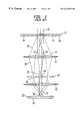
- FIG. 1 is a schematic illustration of apparatus in which the present invention may be incorporated;
- FIG. 2 is a perspective view, with the upper plate removed, showing an embodiment of the present invention
- FIG. 3 is a top plan view of the embodiment shown in FIG. 2;
- FIG. 4 is a partial cross sectional view illustrating the air bearing pads and vacuum isolation.
- FIG. 5 schematically shows the feeding of air from a drive shaft air bearing to a journal bearing.
- FIG. 1 illustrates an environment in which the present invention finds utility.
- FIG. 1 discloses an illustrative projection lithography apparatus where radiation such as electron beam radiation 10 is introduced incident onto a mask 12 .
- the mask 12 has a first region 14 that is transparent to the incident radiation 10 and a second region 16 that scatters the incident radiation 10 that is transmitted therethrough.
- the radiation beams scattered by the mask 12 are designated as the beams 18
- the radiation beams that are unscattered are designated as 20 .
- the unscattered radiation 20 is transmitted through the lens 22 and directed through an image aperture 24 in a back focal plane filter 26 .
- the back focal plane filter 26 also has proximity effect correction apertures 28 .
- a portion of the scattered radiation 18 that is transmitted through the first lens 22 passes through the proximity effect correction apertures 28 .
- the untransmitted portion of the scattered radiation (not shown) is absorbed by the back focal plane filter 26 .
- the radiation that passes through the image aperture 24 and the proximity effect correction apertures 28 is incident on a second lens 30 .
- the second lens 30 directs the unscattered radiation 20 onto an energy sensitive material 32 formed on a wafer 34 .
- the unscattered radiation 20 forms an image of the mask 12 in the energy sensitive material 32 .
- the second lens 30 has aberrations therein which focuses the scattered radiation 18 incident thereon in a plane 36 different from the surface of the energy sensitive material 32 .
- the mask 12 and the wafer 34 are larger than the optics (i.e., the lens 22 , the filter 26 , and the lens 30 ).
- a small section of the mask 12 is utilized to expose a small section of the wafer 34 , and then the mask 12 and the wafer 34 are moved to effect either a simultaneous scan of the mask 12 and the wafer 34 or an incremental stepping of the mask 12 and the wafer 34 .
- the present invention is concerned with the stages utilized to move the mask 12 and the wafer 34 .
- FIGS. 2-5 An illustrative stage mechanism according to the present invention is shown schematically in FIGS. 2-5.
- the mechanism includes a platform 38 on which is secured a holder 40 for holding either a mask or a wafer.
- the platform 38 is a substantially rectangular planar block.
- the holder 40 has a central opening 42 which is in registration with an opening 44 through the platform 38 .
- the platform 38 is arranged for movement in the X and Y directions, as defined by the coordinate arrows 46 .
- a shaft 48 is secured along a first edge 50 of the platform 38 and is oriented axially in the X direction.
- a second shaft 52 is secured along a second edge 54 of the platform 38 and is oriented axially in the Y direction.
- a bearing 56 supports the shaft 48 for axial movement and a bearing 58 supports the shaft 52 for axial movement.
- the bearings 56 , 58 are preferably sleeve air-bearings.
- a linear drive shaft 60 is oriented axially in the Y direction and has a first end secured to the bearing 56 .
- another drive shaft 62 is spaced from and parallel to the drive shaft 60 and likewise has an end secured to the bearing 56 .
- a linear drive shaft 64 is oriented axially in the X direction and has an end secured to the bearing 58 .
- each of the drive shaft 60 , 62 , 64 is coupled at its end opposite a respective bearing 56 , 58 to a linear drive mechanism, such as, for example, a linear motor, arranged to move axially the respective drive shaft 60 , 62 , 64 .
- a linear drive mechanism such as, for example, a linear motor
- the platform 38 , the shafts 48 , 52 and the drive shafts 60 , 62 , 64 all lie substantially in a single plane. This minimizes the space taken up by the stage mechanism.
- the use of two drive shafts 60 , 62 along one of the axes, illustratively the Y axis, provides yaw control by differentially driving the drive shafts 60 , 62 .
- the drive shafts 60 , 62 , 64 are formed with flexures 66 , 68 , 70 , 72 , 76 , 78 .
- the combination of the flexured drive shafts 60 , 62 , 64 and the bearings 56 , 58 decouples the drive axes from each other and isolates the platform 38 from external moments.
- a lower plate 78 and an upper plate 80 To support the platform 38 for planar movement, there is provided a lower plate 78 and an upper plate 80 .
- the plates 78 , 80 are formed with openings 82 , 84 , respectively, surrounding the holder 40 .
- opposed pairs of planar air-bearing pads are provided in the plates 78 , 80 near the corners of the openings 82 , 84 .
- a lower planar air-bearing pad 86 is provided in the lower plate 78 and is across the platform 38 from the air-bearing pad 88 provided in the upper plate 80 .
- the air-bearing pad 88 provides a downward preload to the platform 38 , as schematically illustrated by the spring 90 .
- the holder 40 may be required to be in a vacuum, as for example, when the aforedescribed apparatus is used in a projection electron beam lithography tool.
- the vacuum is maintained within the openings 82 , 84 of the plates 78 , 80 .
- the platform 38 is designed such that the flat and parallel surfaces have low porosity and are good gas barriers.
- the central portion of the platform 38 is pumped and isolated from the peripheral portion of the platform 38 via planar differentially pumped seals. These seals consist of a number of concentric pumping channels 92 , 94 , 96 in each of the plates 78 , 80 between the bearing pads 86 , 88 and the openings 82 , 84 .
- the channels 92 , 94 , 96 are used to progressively evacuate gas from the surfaces of the platform 38 and from the leak formed between the platform 38 and the plates 78 , 80 .
- air-bearings with differentially pumped vacuum isolation have been used in other applications, they are often limited by the conductance of the vacuum plumbing.
- progressively higher vacuum levels must be maintained between pumping stages (vacuum levels within concentric pumping channels must improve by as much as three orders of magnitude per stage).
- the described differential pumping configuration allows much better isolation by accommodating large pumping channels which provide the required molecular flow to the final high vacuum pumping stages.
- a problem overcome by the present invention is to provide an air supply to the bearings 56 , 58 , which are preferably sleeve air-bearings. Since these bearings 56 , 58 move with respect to the plates 78 , 80 , some means must be provided for providing air to the bearings 56 , 58 without having flexible hoses or the like which could get entangled or interfere with movement of the platform 38 . This problem is obviated by providing an air-bearing 98 , 100 for each of the drive shafts 60 , 62 , 64 . As shown in FIG.
- the drive shaft 60 (as well as the drive shafts 62 , 64 ) is provided with an internal passageway 102 which has a first end opening to the periphery of the drive shaft 60 within the air-bearing 98 .
- the air-bearing 98 is sufficiently long that the opening of the passageway 102 therein remains within the air-bearing 98 over the entire range of travel of the drive shaft 60 .
- the other end of the passageway 102 opens to the periphery of the drive shaft 60 between the air-bearing 98 and the end of the drive shaft 60 which is connected to the bearing 56 .
- Piping 104 is coupled between the passageway 102 and the bearing 56 . This piping 104 can be rigid so as to not interfere with movement of the platform 38 .
Abstract
Description
Claims (10)
Priority Applications (1)
| Application Number | Priority Date | Filing Date | Title |
|---|---|---|---|
| US09/413,149 US6324933B1 (en) | 1999-10-06 | 1999-10-06 | Planar movable stage mechanism |
Applications Claiming Priority (1)
| Application Number | Priority Date | Filing Date | Title |
|---|---|---|---|
| US09/413,149 US6324933B1 (en) | 1999-10-06 | 1999-10-06 | Planar movable stage mechanism |
Publications (1)
| Publication Number | Publication Date |
|---|---|
| US6324933B1 true US6324933B1 (en) | 2001-12-04 |
Family
ID=23636050
Family Applications (1)
| Application Number | Title | Priority Date | Filing Date |
|---|---|---|---|
| US09/413,149 Expired - Lifetime US6324933B1 (en) | 1999-10-06 | 1999-10-06 | Planar movable stage mechanism |
Country Status (1)
| Country | Link |
|---|---|
| US (1) | US6324933B1 (en) |
Cited By (22)
| Publication number | Priority date | Publication date | Assignee | Title |
|---|---|---|---|---|
| US6555829B1 (en) * | 2000-01-10 | 2003-04-29 | Applied Materials, Inc. | High precision flexure stage |
| US6647632B2 (en) * | 2001-02-05 | 2003-11-18 | Hitachi Kokusai Electric Inc. | Position measuring apparatus |
| US20050094123A1 (en) * | 2003-10-29 | 2005-05-05 | Wojcik Leszek A. | Alignable low-profile substrate chuck for large-area projection lithography |
| US20050129339A1 (en) * | 2003-11-20 | 2005-06-16 | Canon Kabushiki Kaisha | Static gas bearing system, stage mechanism, exposure apparatus, and device manufacturing method |
| US7239107B1 (en) | 2006-02-24 | 2007-07-03 | The Board Of Trustees Of The University Of Illinois | Flexure stage |
| US20080166213A1 (en) * | 2007-01-05 | 2008-07-10 | Bradley Hunter | High-speed substrate manipulator |
| US20080292392A1 (en) * | 2007-05-21 | 2008-11-27 | Usa As Represented By The Administrator Of The National Aeronautics And Space Administrator | Flexure Based Linear and Rotary Bearings |
| EP2030723A1 (en) * | 2007-09-03 | 2009-03-04 | Korea Institute Of Machinery & Materials | Planar stage moving apparatus for machine |
| US20090056158A1 (en) * | 2007-09-05 | 2009-03-05 | Makoto Tada | Positive Load Alignment Mechanism |
| US20100077877A1 (en) * | 2008-09-26 | 2010-04-01 | Ming-Hung Hsieh | Rotary micro-adjustment mechanism for a synchronous double-drive positioning platform |
| US20100095798A1 (en) * | 2008-10-16 | 2010-04-22 | Industrial Technology Research Institute | Planar moving apparatus |
| US20100116161A1 (en) * | 2007-06-01 | 2010-05-13 | Vijay Shilpiekandula | High resolution flexural stage for in-plane position and out-of-plane pitch/roll alignment |
| EP2187434A1 (en) * | 2008-11-17 | 2010-05-19 | Vistec Electron Beam GmbH | Aerostatically guided table system for vacuum application |
| CN101354245B (en) * | 2007-07-26 | 2010-11-10 | 鸿富锦精密工业(深圳)有限公司 | Bearing platform and measuring device using the same |
| US20110022227A1 (en) * | 2009-07-23 | 2011-01-27 | Kla-Tencor Corporation | Dual Scanning Stage |
| ITVR20090130A1 (en) * | 2009-09-03 | 2011-03-04 | Raffaele Tomelleri | HIGH PRECISION X-Y SLEDGE |
| CN103963033A (en) * | 2014-05-20 | 2014-08-06 | 广东工业大学 | One-dimensional micro-positioning platform with adjustable rigidity frequency based on stress rigidization principle |
| CN103990998A (en) * | 2014-05-20 | 2014-08-20 | 广东工业大学 | Stiffness frequency adjustable two-dimensional micro-motion platform based on stress stiffening principle |
| WO2015092038A1 (en) * | 2013-12-20 | 2015-06-25 | Centrotherm Photovoltaics Ag | Wafer boat |
| US20170316913A1 (en) * | 2014-11-12 | 2017-11-02 | Phenom-World Holding B.V. | Sample Stage |
| CN107393599A (en) * | 2017-07-25 | 2017-11-24 | 西安交通大学 | Integrate the quick deflection platform of two dimension and method of sensing unit and confinement element |
| US20220106926A1 (en) * | 2017-05-09 | 2022-04-07 | Frauscher Holding Gmbh | Hot air engine having a step piston |
Citations (28)
| Publication number | Priority date | Publication date | Assignee | Title |
|---|---|---|---|---|
| US1851028A (en) * | 1929-12-11 | 1932-03-29 | Louis J Kolb | Vacuum table |
| US3495519A (en) * | 1967-02-01 | 1970-02-17 | Microform Data Systems | Xy table |
| US3918167A (en) * | 1974-03-01 | 1975-11-11 | Gerber Scientific Instr Co | Apparatus for sensing relative movement of a work table and tool |
| US4392642A (en) * | 1980-12-22 | 1983-07-12 | Anorad Corporation | Workpiece positioning table with air bearing pads |
| US4477978A (en) * | 1982-10-01 | 1984-10-23 | Toyota Jidosha Kabushiki Kaisha | Dimension measuring apparatus |
| US4630942A (en) * | 1984-01-20 | 1986-12-23 | Hitachi, Ltd. | Guiding apparatus |
| US4887360A (en) * | 1989-02-03 | 1989-12-19 | The Warner & Swasey Company | Way bearing arrangement for a horizontal arm coordinate measuring machine |
| US5092193A (en) * | 1990-06-06 | 1992-03-03 | Ken Yanagisawa | Drive system |
| US5105552A (en) * | 1987-09-09 | 1992-04-21 | Institut Superieur D'etat De Surface (I S E S) | Procedure and sliding support for a profilometer |
| US5130213A (en) | 1989-08-07 | 1992-07-14 | At&T Bell Laboratories | Device manufacture involving lithographic processing |
| US5130523A (en) * | 1991-04-22 | 1992-07-14 | Raleigh Freddie L | Coordinate measuring machine with improved flexure and clamp for fiber optic connection |
| US5140242A (en) * | 1990-04-30 | 1992-08-18 | International Business Machines Corporation | Servo guided stage system |
| US5355744A (en) * | 1992-05-12 | 1994-10-18 | Ken Yanagisawa | Two dimensional drive system |
| US5408750A (en) * | 1992-04-09 | 1995-04-25 | Mitutoyo Corporation | X-Y table apparatus |
| US5561299A (en) * | 1994-08-18 | 1996-10-01 | Fujitsu Limited | X-Y stage and charged particle beam exposure apparatus |
| US5574556A (en) | 1993-06-30 | 1996-11-12 | Canon Kabushiki Kaisha | Stage mechanism in exposure apparatus |
| US5603243A (en) * | 1993-11-11 | 1997-02-18 | Armstrong Projects Limited | Improvements in or relating to alignment apparatus |
| US5663568A (en) | 1995-10-20 | 1997-09-02 | Lucent Technologies Inc. | Apparatus for controlling a charged particle beam and a lithographic process in which the apparatus is used |
| US5701014A (en) | 1995-01-27 | 1997-12-23 | Lucent Technologies Inc. | Projection lithography apparatus |
| US5744924A (en) | 1994-04-01 | 1998-04-28 | Nikon Corporation | Guideless stage with isolated reaction frame |
| US5757160A (en) * | 1996-12-23 | 1998-05-26 | Svg Lithography Systems, Inc. | Moving interferometer wafer stage |
| US5760564A (en) | 1995-06-27 | 1998-06-02 | Nikon Precision Inc. | Dual guide beam stage mechanism with yaw control |
| US5806193A (en) | 1995-11-09 | 1998-09-15 | Nikon Corporation | Tilt and movement apparatus using flexure and air cylinder |
| US5839324A (en) * | 1995-06-15 | 1998-11-24 | Nikon Corporation | Stage apparatus and exposure apparatus provided with the stage apparatus |
| US5874820A (en) | 1995-04-04 | 1999-02-23 | Nikon Corporation | Window frame-guided stage mechanism |
| US5883703A (en) | 1996-02-08 | 1999-03-16 | Megapanel Corporation | Methods and apparatus for detecting and compensating for focus errors in a photolithography tool |
| US6025689A (en) * | 1997-02-06 | 2000-02-15 | Speedline Technologies, Inc. | Positioning system |
| US6028376A (en) * | 1997-04-22 | 2000-02-22 | Canon Kabushiki Kaisha | Positioning apparatus and exposure apparatus using the same |
-
1999
- 1999-10-06 US US09/413,149 patent/US6324933B1/en not_active Expired - Lifetime
Patent Citations (28)
| Publication number | Priority date | Publication date | Assignee | Title |
|---|---|---|---|---|
| US1851028A (en) * | 1929-12-11 | 1932-03-29 | Louis J Kolb | Vacuum table |
| US3495519A (en) * | 1967-02-01 | 1970-02-17 | Microform Data Systems | Xy table |
| US3918167A (en) * | 1974-03-01 | 1975-11-11 | Gerber Scientific Instr Co | Apparatus for sensing relative movement of a work table and tool |
| US4392642A (en) * | 1980-12-22 | 1983-07-12 | Anorad Corporation | Workpiece positioning table with air bearing pads |
| US4477978A (en) * | 1982-10-01 | 1984-10-23 | Toyota Jidosha Kabushiki Kaisha | Dimension measuring apparatus |
| US4630942A (en) * | 1984-01-20 | 1986-12-23 | Hitachi, Ltd. | Guiding apparatus |
| US5105552A (en) * | 1987-09-09 | 1992-04-21 | Institut Superieur D'etat De Surface (I S E S) | Procedure and sliding support for a profilometer |
| US4887360A (en) * | 1989-02-03 | 1989-12-19 | The Warner & Swasey Company | Way bearing arrangement for a horizontal arm coordinate measuring machine |
| US5130213A (en) | 1989-08-07 | 1992-07-14 | At&T Bell Laboratories | Device manufacture involving lithographic processing |
| US5140242A (en) * | 1990-04-30 | 1992-08-18 | International Business Machines Corporation | Servo guided stage system |
| US5092193A (en) * | 1990-06-06 | 1992-03-03 | Ken Yanagisawa | Drive system |
| US5130523A (en) * | 1991-04-22 | 1992-07-14 | Raleigh Freddie L | Coordinate measuring machine with improved flexure and clamp for fiber optic connection |
| US5408750A (en) * | 1992-04-09 | 1995-04-25 | Mitutoyo Corporation | X-Y table apparatus |
| US5355744A (en) * | 1992-05-12 | 1994-10-18 | Ken Yanagisawa | Two dimensional drive system |
| US5574556A (en) | 1993-06-30 | 1996-11-12 | Canon Kabushiki Kaisha | Stage mechanism in exposure apparatus |
| US5603243A (en) * | 1993-11-11 | 1997-02-18 | Armstrong Projects Limited | Improvements in or relating to alignment apparatus |
| US5744924A (en) | 1994-04-01 | 1998-04-28 | Nikon Corporation | Guideless stage with isolated reaction frame |
| US5561299A (en) * | 1994-08-18 | 1996-10-01 | Fujitsu Limited | X-Y stage and charged particle beam exposure apparatus |
| US5701014A (en) | 1995-01-27 | 1997-12-23 | Lucent Technologies Inc. | Projection lithography apparatus |
| US5874820A (en) | 1995-04-04 | 1999-02-23 | Nikon Corporation | Window frame-guided stage mechanism |
| US5839324A (en) * | 1995-06-15 | 1998-11-24 | Nikon Corporation | Stage apparatus and exposure apparatus provided with the stage apparatus |
| US5760564A (en) | 1995-06-27 | 1998-06-02 | Nikon Precision Inc. | Dual guide beam stage mechanism with yaw control |
| US5663568A (en) | 1995-10-20 | 1997-09-02 | Lucent Technologies Inc. | Apparatus for controlling a charged particle beam and a lithographic process in which the apparatus is used |
| US5806193A (en) | 1995-11-09 | 1998-09-15 | Nikon Corporation | Tilt and movement apparatus using flexure and air cylinder |
| US5883703A (en) | 1996-02-08 | 1999-03-16 | Megapanel Corporation | Methods and apparatus for detecting and compensating for focus errors in a photolithography tool |
| US5757160A (en) * | 1996-12-23 | 1998-05-26 | Svg Lithography Systems, Inc. | Moving interferometer wafer stage |
| US6025689A (en) * | 1997-02-06 | 2000-02-15 | Speedline Technologies, Inc. | Positioning system |
| US6028376A (en) * | 1997-04-22 | 2000-02-22 | Canon Kabushiki Kaisha | Positioning apparatus and exposure apparatus using the same |
Cited By (39)
| Publication number | Priority date | Publication date | Assignee | Title |
|---|---|---|---|---|
| US6555829B1 (en) * | 2000-01-10 | 2003-04-29 | Applied Materials, Inc. | High precision flexure stage |
| US6647632B2 (en) * | 2001-02-05 | 2003-11-18 | Hitachi Kokusai Electric Inc. | Position measuring apparatus |
| US6903808B2 (en) * | 2003-10-29 | 2005-06-07 | Anvik Corporation | Alignable low-profile substrate chuck for large-area projection lithography |
| US20050094123A1 (en) * | 2003-10-29 | 2005-05-05 | Wojcik Leszek A. | Alignable low-profile substrate chuck for large-area projection lithography |
| US20050129339A1 (en) * | 2003-11-20 | 2005-06-16 | Canon Kabushiki Kaisha | Static gas bearing system, stage mechanism, exposure apparatus, and device manufacturing method |
| US7207720B2 (en) * | 2003-11-20 | 2007-04-24 | Canon Kabushiki Kaisha | Static gas bearing system, stage mechanism, exposure apparatus, and device manufacturing method |
| US7239107B1 (en) | 2006-02-24 | 2007-07-03 | The Board Of Trustees Of The University Of Illinois | Flexure stage |
| US20080166213A1 (en) * | 2007-01-05 | 2008-07-10 | Bradley Hunter | High-speed substrate manipulator |
| US7898204B2 (en) | 2007-01-05 | 2011-03-01 | Active Precision, Inc. | High-speed substrate manipulator |
| US20080292392A1 (en) * | 2007-05-21 | 2008-11-27 | Usa As Represented By The Administrator Of The National Aeronautics And Space Administrator | Flexure Based Linear and Rotary Bearings |
| US9371855B2 (en) | 2007-05-21 | 2016-06-21 | The United States Of America As Represented By The Administrator Of The National Aeronautics And Space Administration | Flexure based linear and rotary bearings |
| US20100116161A1 (en) * | 2007-06-01 | 2010-05-13 | Vijay Shilpiekandula | High resolution flexural stage for in-plane position and out-of-plane pitch/roll alignment |
| US8390233B2 (en) * | 2007-06-01 | 2013-03-05 | Massachusetts Institute Of Technology | High resolution flexural stage for in-plane position and out-of-plane pitch/roll alignment |
| CN101354245B (en) * | 2007-07-26 | 2010-11-10 | 鸿富锦精密工业(深圳)有限公司 | Bearing platform and measuring device using the same |
| EP2030723A1 (en) * | 2007-09-03 | 2009-03-04 | Korea Institute Of Machinery & Materials | Planar stage moving apparatus for machine |
| US20090056594A1 (en) * | 2007-09-03 | 2009-03-05 | Korea Institute Of Machinery & Materials | Planar stage moving apparatus for machine |
| US8008815B2 (en) | 2007-09-03 | 2011-08-30 | Korea Institute Of Machinery & Materials | Planar stage moving apparatus for machine |
| US7607234B2 (en) * | 2007-09-05 | 2009-10-27 | Hiwin Mikrosystem Corp. | Positive load alignment mechanism |
| US20090056158A1 (en) * | 2007-09-05 | 2009-03-05 | Makoto Tada | Positive Load Alignment Mechanism |
| US20100077877A1 (en) * | 2008-09-26 | 2010-04-01 | Ming-Hung Hsieh | Rotary micro-adjustment mechanism for a synchronous double-drive positioning platform |
| US20100095798A1 (en) * | 2008-10-16 | 2010-04-22 | Industrial Technology Research Institute | Planar moving apparatus |
| US20100122603A1 (en) * | 2008-11-17 | 2010-05-20 | Vistec Electron Beam Gmbh | Aerostatically Guided Table System for Vacuum Application |
| US8496221B2 (en) | 2008-11-17 | 2013-07-30 | Vistec Electron Beam Gmbh | Aerostatically guided table system for vacuum application |
| EP2187434A1 (en) * | 2008-11-17 | 2010-05-19 | Vistec Electron Beam GmbH | Aerostatically guided table system for vacuum application |
| US20110022227A1 (en) * | 2009-07-23 | 2011-01-27 | Kla-Tencor Corporation | Dual Scanning Stage |
| US8285418B2 (en) * | 2009-07-23 | 2012-10-09 | Kla-Tencor Corporation | Dual scanning stage |
| ITVR20090130A1 (en) * | 2009-09-03 | 2011-03-04 | Raffaele Tomelleri | HIGH PRECISION X-Y SLEDGE |
| WO2015092038A1 (en) * | 2013-12-20 | 2015-06-25 | Centrotherm Photovoltaics Ag | Wafer boat |
| CN103990998A (en) * | 2014-05-20 | 2014-08-20 | 广东工业大学 | Stiffness frequency adjustable two-dimensional micro-motion platform based on stress stiffening principle |
| CN103963033A (en) * | 2014-05-20 | 2014-08-06 | 广东工业大学 | One-dimensional micro-positioning platform with adjustable rigidity frequency based on stress rigidization principle |
| CN103963033B (en) * | 2014-05-20 | 2016-06-29 | 广东工业大学 | The one-dimensional micromotion platform of rigidity frequency-adjustable based on Stress stiffening principle |
| CN103990998B (en) * | 2014-05-20 | 2017-01-25 | 广东工业大学 | Stiffness frequency adjustable two-dimensional micro-motion platform based on stress stiffening principle |
| US20170316913A1 (en) * | 2014-11-12 | 2017-11-02 | Phenom-World Holding B.V. | Sample Stage |
| US10580613B2 (en) * | 2014-11-12 | 2020-03-03 | Phenom-World Holding B.V. | Sample stage |
| EP3809446A1 (en) * | 2014-11-12 | 2021-04-21 | Phenom-World Holding B.V. | Sample stage |
| US20220106926A1 (en) * | 2017-05-09 | 2022-04-07 | Frauscher Holding Gmbh | Hot air engine having a step piston |
| US11725607B2 (en) * | 2017-05-09 | 2023-08-15 | Frauscher Holding Gmbh | Hot air engine having a step piston |
| CN107393599A (en) * | 2017-07-25 | 2017-11-24 | 西安交通大学 | Integrate the quick deflection platform of two dimension and method of sensing unit and confinement element |
| WO2019019718A1 (en) * | 2017-07-25 | 2019-01-31 | 西安交通大学 | Two-dimensional fast deflection table integrating sensing unit and constraint element and method |
Similar Documents
| Publication | Publication Date | Title |
|---|---|---|
| US6324933B1 (en) | Planar movable stage mechanism | |
| US7394076B2 (en) | Moving vacuum chamber stage with air bearing and differentially pumped grooves | |
| US6600547B2 (en) | Sliding seal | |
| US7280185B2 (en) | Stage system including fine-motion cable unit, exposure apparatus, and method of manufacturing device | |
| US8508718B2 (en) | Wafer table having sensor for immersion lithography | |
| JP2974535B2 (en) | Positioning device | |
| US6188195B1 (en) | Exposure method, and method of making exposure apparatus having dynamically isolated support structure | |
| US4425508A (en) | Electron beam lithographic apparatus | |
| CA1037506A (en) | Workpiece positioning apparatus | |
| US6888620B2 (en) | System and method for holding a device with minimal deformation | |
| JPS6052025A (en) | Lithographic device | |
| US7009685B2 (en) | Bearing arrangement for reaction mass in a controlled environment | |
| US7642523B1 (en) | Vacuum chamber stage with application of vacuum from below | |
| US20080024749A1 (en) | Low mass six degree of freedom stage for lithography tools | |
| US20020043163A1 (en) | Low distortion kinematic reticle support | |
| JP4144179B2 (en) | Hydrostatic gas bearing, stage apparatus using the same, and optical apparatus using the same | |
| US6781138B2 (en) | Positioning stage with stationary actuators | |
| US20040080730A1 (en) | System and method for clamping a device holder with reduced deformation | |
| US6467960B1 (en) | Air bearing linear guide for use in a vacuum | |
| US20030098664A1 (en) | Holder mover for a stage assembly | |
| US20030098965A1 (en) | System and method for supporting a device holder with separate components | |
| US6903346B2 (en) | Stage assembly having a follower assembly | |
| US20030178579A1 (en) | Stage devices exhibiting reduced deformation, and microlithography systems comprising same | |
| JP4310065B2 (en) | Stage equipment | |
| US20030098963A1 (en) | Fluid connector for a stage assembly |
Legal Events
| Date | Code | Title | Description |
|---|---|---|---|
| AS | Assignment |
Owner name: LUCENT TECHNOLOGIES INC., NEW JERSEY Free format text: ASSIGNMENT OF ASSIGNORS INTEREST;ASSIGNORS:WASKIEWICZ, WARREN K.;WERDER, KURT S.;REEL/FRAME:010305/0632 Effective date: 19991005 |
|
| AS | Assignment |
Owner name: DARPA, VIRGINIA Free format text: CONFIRMATORY LICENSE;ASSIGNOR:LUCENT TECHNOLOGIES;REEL/FRAME:012099/0265 Effective date: 20010815 |
|
| STCF | Information on status: patent grant |
Free format text: PATENTED CASE |
|
| FPAY | Fee payment |
Year of fee payment: 4 |
|
| FPAY | Fee payment |
Year of fee payment: 8 |
|
| FPAY | Fee payment |
Year of fee payment: 12 |
|
| AS | Assignment |
Owner name: DEUTSCHE BANK AG NEW YORK BRANCH, AS COLLATERAL AG Free format text: PATENT SECURITY AGREEMENT;ASSIGNORS:LSI CORPORATION;AGERE SYSTEMS LLC;REEL/FRAME:032856/0031 Effective date: 20140506 |
|
| AS | Assignment |
Owner name: AVAGO TECHNOLOGIES GENERAL IP (SINGAPORE) PTE. LTD Free format text: ASSIGNMENT OF ASSIGNORS INTEREST;ASSIGNOR:AGERE SYSTEMS LLC;REEL/FRAME:035365/0634 Effective date: 20140804 |
|
| AS | Assignment |
Owner name: AGERE SYSTEMS LLC, PENNSYLVANIA Free format text: TERMINATION AND RELEASE OF SECURITY INTEREST IN PATENT RIGHTS (RELEASES RF 032856-0031);ASSIGNOR:DEUTSCHE BANK AG NEW YORK BRANCH, AS COLLATERAL AGENT;REEL/FRAME:037684/0039 Effective date: 20160201 Owner name: LSI CORPORATION, CALIFORNIA Free format text: TERMINATION AND RELEASE OF SECURITY INTEREST IN PATENT RIGHTS (RELEASES RF 032856-0031);ASSIGNOR:DEUTSCHE BANK AG NEW YORK BRANCH, AS COLLATERAL AGENT;REEL/FRAME:037684/0039 Effective date: 20160201 |
|
| AS | Assignment |
Owner name: BANK OF AMERICA, N.A., AS COLLATERAL AGENT, NORTH CAROLINA Free format text: PATENT SECURITY AGREEMENT;ASSIGNOR:AVAGO TECHNOLOGIES GENERAL IP (SINGAPORE) PTE. LTD.;REEL/FRAME:037808/0001 Effective date: 20160201 Owner name: BANK OF AMERICA, N.A., AS COLLATERAL AGENT, NORTH Free format text: PATENT SECURITY AGREEMENT;ASSIGNOR:AVAGO TECHNOLOGIES GENERAL IP (SINGAPORE) PTE. LTD.;REEL/FRAME:037808/0001 Effective date: 20160201 |
|
| AS | Assignment |
Owner name: AVAGO TECHNOLOGIES GENERAL IP (SINGAPORE) PTE. LTD., SINGAPORE Free format text: TERMINATION AND RELEASE OF SECURITY INTEREST IN PATENTS;ASSIGNOR:BANK OF AMERICA, N.A., AS COLLATERAL AGENT;REEL/FRAME:041710/0001 Effective date: 20170119 Owner name: AVAGO TECHNOLOGIES GENERAL IP (SINGAPORE) PTE. LTD Free format text: TERMINATION AND RELEASE OF SECURITY INTEREST IN PATENTS;ASSIGNOR:BANK OF AMERICA, N.A., AS COLLATERAL AGENT;REEL/FRAME:041710/0001 Effective date: 20170119 |
|
| AS | Assignment |
Owner name: BELL SEMICONDUCTOR, LLC, ILLINOIS Free format text: ASSIGNMENT OF ASSIGNORS INTEREST;ASSIGNORS:AVAGO TECHNOLOGIES GENERAL IP (SINGAPORE) PTE. LTD.;BROADCOM CORPORATION;REEL/FRAME:044886/0608 Effective date: 20171208 |
|
| AS | Assignment |
Owner name: CORTLAND CAPITAL MARKET SERVICES LLC, AS COLLATERA Free format text: SECURITY INTEREST;ASSIGNORS:HILCO PATENT ACQUISITION 56, LLC;BELL SEMICONDUCTOR, LLC;BELL NORTHERN RESEARCH, LLC;REEL/FRAME:045216/0020 Effective date: 20180124 |
|
| AS | Assignment |
Owner name: BELL NORTHERN RESEARCH, LLC, ILLINOIS Free format text: RELEASE BY SECURED PARTY;ASSIGNOR:CORTLAND CAPITAL MARKET SERVICES LLC;REEL/FRAME:059720/0719 Effective date: 20220401 Owner name: BELL SEMICONDUCTOR, LLC, ILLINOIS Free format text: RELEASE BY SECURED PARTY;ASSIGNOR:CORTLAND CAPITAL MARKET SERVICES LLC;REEL/FRAME:059720/0719 Effective date: 20220401 Owner name: HILCO PATENT ACQUISITION 56, LLC, ILLINOIS Free format text: RELEASE BY SECURED PARTY;ASSIGNOR:CORTLAND CAPITAL MARKET SERVICES LLC;REEL/FRAME:059720/0719 Effective date: 20220401 |