US6339120B1 - Method of preparing thermally conductive compounds by liquid metal bridged particle clusters - Google Patents
Method of preparing thermally conductive compounds by liquid metal bridged particle clusters Download PDFInfo
- Publication number
- US6339120B1 US6339120B1 US09/543,661 US54366100A US6339120B1 US 6339120 B1 US6339120 B1 US 6339120B1 US 54366100 A US54366100 A US 54366100A US 6339120 B1 US6339120 B1 US 6339120B1
- Authority
- US
- United States
- Prior art keywords
- thermally conductive
- liquid
- particulate
- liquid metal
- alloy
- Prior art date
- Legal status (The legal status is an assumption and is not a legal conclusion. Google has not performed a legal analysis and makes no representation as to the accuracy of the status listed.)
- Expired - Lifetime
Links
Images


Classifications
-
- H—ELECTRICITY
- H01—ELECTRIC ELEMENTS
- H01L—SEMICONDUCTOR DEVICES NOT COVERED BY CLASS H10
- H01L23/00—Details of semiconductor or other solid state devices
- H01L23/34—Arrangements for cooling, heating, ventilating or temperature compensation ; Temperature sensing arrangements
- H01L23/36—Selection of materials, or shaping, to facilitate cooling or heating, e.g. heatsinks
- H01L23/373—Cooling facilitated by selection of materials for the device or materials for thermal expansion adaptation, e.g. carbon
- H01L23/3737—Organic materials with or without a thermoconductive filler
-
- H—ELECTRICITY
- H01—ELECTRIC ELEMENTS
- H01L—SEMICONDUCTOR DEVICES NOT COVERED BY CLASS H10
- H01L23/00—Details of semiconductor or other solid state devices
- H01L23/34—Arrangements for cooling, heating, ventilating or temperature compensation ; Temperature sensing arrangements
- H01L23/36—Selection of materials, or shaping, to facilitate cooling or heating, e.g. heatsinks
- H01L23/373—Cooling facilitated by selection of materials for the device or materials for thermal expansion adaptation, e.g. carbon
- H01L23/3736—Metallic materials
-
- H—ELECTRICITY
- H01—ELECTRIC ELEMENTS
- H01L—SEMICONDUCTOR DEVICES NOT COVERED BY CLASS H10
- H01L24/00—Arrangements for connecting or disconnecting semiconductor or solid-state bodies; Methods or apparatus related thereto
- H01L24/01—Means for bonding being attached to, or being formed on, the surface to be connected, e.g. chip-to-package, die-attach, "first-level" interconnects; Manufacturing methods related thereto
- H01L24/26—Layer connectors, e.g. plate connectors, solder or adhesive layers; Manufacturing methods related thereto
- H01L24/28—Structure, shape, material or disposition of the layer connectors prior to the connecting process
- H01L24/29—Structure, shape, material or disposition of the layer connectors prior to the connecting process of an individual layer connector
-
- F—MECHANICAL ENGINEERING; LIGHTING; HEATING; WEAPONS; BLASTING
- F28—HEAT EXCHANGE IN GENERAL
- F28F—DETAILS OF HEAT-EXCHANGE AND HEAT-TRANSFER APPARATUS, OF GENERAL APPLICATION
- F28F13/00—Arrangements for modifying heat-transfer, e.g. increasing, decreasing
- F28F2013/005—Thermal joints
- F28F2013/006—Heat conductive materials
-
- H—ELECTRICITY
- H01—ELECTRIC ELEMENTS
- H01L—SEMICONDUCTOR DEVICES NOT COVERED BY CLASS H10
- H01L2224/00—Indexing scheme for arrangements for connecting or disconnecting semiconductor or solid-state bodies and methods related thereto as covered by H01L24/00
- H01L2224/01—Means for bonding being attached to, or being formed on, the surface to be connected, e.g. chip-to-package, die-attach, "first-level" interconnects; Manufacturing methods related thereto
- H01L2224/26—Layer connectors, e.g. plate connectors, solder or adhesive layers; Manufacturing methods related thereto
- H01L2224/28—Structure, shape, material or disposition of the layer connectors prior to the connecting process
- H01L2224/29—Structure, shape, material or disposition of the layer connectors prior to the connecting process of an individual layer connector
- H01L2224/29001—Core members of the layer connector
- H01L2224/29099—Material
- H01L2224/29198—Material with a principal constituent of the material being a combination of two or more materials in the form of a matrix with a filler, i.e. being a hybrid material, e.g. segmented structures, foams
- H01L2224/29199—Material of the matrix
- H01L2224/2929—Material of the matrix with a principal constituent of the material being a polymer, e.g. polyester, phenolic based polymer, epoxy
-
- H—ELECTRICITY
- H01—ELECTRIC ELEMENTS
- H01L—SEMICONDUCTOR DEVICES NOT COVERED BY CLASS H10
- H01L2224/00—Indexing scheme for arrangements for connecting or disconnecting semiconductor or solid-state bodies and methods related thereto as covered by H01L24/00
- H01L2224/01—Means for bonding being attached to, or being formed on, the surface to be connected, e.g. chip-to-package, die-attach, "first-level" interconnects; Manufacturing methods related thereto
- H01L2224/26—Layer connectors, e.g. plate connectors, solder or adhesive layers; Manufacturing methods related thereto
- H01L2224/28—Structure, shape, material or disposition of the layer connectors prior to the connecting process
- H01L2224/29—Structure, shape, material or disposition of the layer connectors prior to the connecting process of an individual layer connector
- H01L2224/29001—Core members of the layer connector
- H01L2224/29099—Material
- H01L2224/29198—Material with a principal constituent of the material being a combination of two or more materials in the form of a matrix with a filler, i.e. being a hybrid material, e.g. segmented structures, foams
- H01L2224/29298—Fillers
- H01L2224/29299—Base material
- H01L2224/29386—Base material with a principal constituent of the material being a non metallic, non metalloid inorganic material
-
- H—ELECTRICITY
- H01—ELECTRIC ELEMENTS
- H01L—SEMICONDUCTOR DEVICES NOT COVERED BY CLASS H10
- H01L2224/00—Indexing scheme for arrangements for connecting or disconnecting semiconductor or solid-state bodies and methods related thereto as covered by H01L24/00
- H01L2224/01—Means for bonding being attached to, or being formed on, the surface to be connected, e.g. chip-to-package, die-attach, "first-level" interconnects; Manufacturing methods related thereto
- H01L2224/26—Layer connectors, e.g. plate connectors, solder or adhesive layers; Manufacturing methods related thereto
- H01L2224/28—Structure, shape, material or disposition of the layer connectors prior to the connecting process
- H01L2224/29—Structure, shape, material or disposition of the layer connectors prior to the connecting process of an individual layer connector
- H01L2224/29001—Core members of the layer connector
- H01L2224/29099—Material
- H01L2224/29198—Material with a principal constituent of the material being a combination of two or more materials in the form of a matrix with a filler, i.e. being a hybrid material, e.g. segmented structures, foams
- H01L2224/29298—Fillers
- H01L2224/29399—Coating material
- H01L2224/294—Coating material with a principal constituent of the material being a metal or a metalloid, e.g. boron [B], silicon [Si], germanium [Ge], arsenic [As], antimony [Sb], tellurium [Te] and polonium [Po], and alloys thereof
-
- H—ELECTRICITY
- H01—ELECTRIC ELEMENTS
- H01L—SEMICONDUCTOR DEVICES NOT COVERED BY CLASS H10
- H01L2224/00—Indexing scheme for arrangements for connecting or disconnecting semiconductor or solid-state bodies and methods related thereto as covered by H01L24/00
- H01L2224/01—Means for bonding being attached to, or being formed on, the surface to be connected, e.g. chip-to-package, die-attach, "first-level" interconnects; Manufacturing methods related thereto
- H01L2224/26—Layer connectors, e.g. plate connectors, solder or adhesive layers; Manufacturing methods related thereto
- H01L2224/31—Structure, shape, material or disposition of the layer connectors after the connecting process
- H01L2224/32—Structure, shape, material or disposition of the layer connectors after the connecting process of an individual layer connector
- H01L2224/321—Disposition
- H01L2224/32151—Disposition the layer connector connecting between a semiconductor or solid-state body and an item not being a semiconductor or solid-state body, e.g. chip-to-substrate, chip-to-passive
- H01L2224/32221—Disposition the layer connector connecting between a semiconductor or solid-state body and an item not being a semiconductor or solid-state body, e.g. chip-to-substrate, chip-to-passive the body and the item being stacked
- H01L2224/32245—Disposition the layer connector connecting between a semiconductor or solid-state body and an item not being a semiconductor or solid-state body, e.g. chip-to-substrate, chip-to-passive the body and the item being stacked the item being metallic
-
- H—ELECTRICITY
- H01—ELECTRIC ELEMENTS
- H01L—SEMICONDUCTOR DEVICES NOT COVERED BY CLASS H10
- H01L2924/00—Indexing scheme for arrangements or methods for connecting or disconnecting semiconductor or solid-state bodies as covered by H01L24/00
- H01L2924/013—Alloys
- H01L2924/0132—Binary Alloys
- H01L2924/01322—Eutectic Alloys, i.e. obtained by a liquid transforming into two solid phases
-
- H—ELECTRICITY
- H01—ELECTRIC ELEMENTS
- H01L—SEMICONDUCTOR DEVICES NOT COVERED BY CLASS H10
- H01L2924/00—Indexing scheme for arrangements or methods for connecting or disconnecting semiconductor or solid-state bodies as covered by H01L24/00
- H01L2924/15—Details of package parts other than the semiconductor or other solid state devices to be connected
- H01L2924/151—Die mounting substrate
- H01L2924/156—Material
- H01L2924/157—Material with a principal constituent of the material being a metal or a metalloid, e.g. boron [B], silicon [Si], germanium [Ge], arsenic [As], antimony [Sb], tellurium [Te] and polonium [Po], and alloys thereof
- H01L2924/15738—Material with a principal constituent of the material being a metal or a metalloid, e.g. boron [B], silicon [Si], germanium [Ge], arsenic [As], antimony [Sb], tellurium [Te] and polonium [Po], and alloys thereof the principal constituent melting at a temperature of greater than or equal to 950 C and less than 1550 C
- H01L2924/15747—Copper [Cu] as principal constituent
-
- H—ELECTRICITY
- H01—ELECTRIC ELEMENTS
- H01L—SEMICONDUCTOR DEVICES NOT COVERED BY CLASS H10
- H01L2924/00—Indexing scheme for arrangements or methods for connecting or disconnecting semiconductor or solid-state bodies as covered by H01L24/00
- H01L2924/30—Technical effects
- H01L2924/301—Electrical effects
- H01L2924/3011—Impedance
Definitions
- the present invention relates generally to a method of preparing thermally conductive mechanically compliant compounds for improving heat transfer from a heat generating semiconductor device to a heat dissipator such as a heat sink or heat spreader. More specifically, the present invention relates to a technique for preparing highly thermally conductive polymer compounds such as a polymer liquid loaded or filled with percolating particulate clusters coated with a liquid metal. Such compounds are highly effective through liquid metal enhanced percolation. More particularly, the present invention involves a process for uniformly coating particulate solids with a liquid metal, and thereafter blending the coated particulate with a liquid or fluid polymer for forming the compliant pad with thermal vias therein.
- liquid metals have been proposed for incorporation in thermally conductive pastes for heat generating semiconductor devices.
- the application of liquid metals for this purpose was not widely used, primarily because of problems created with the tendency of the liquid metal to form alloys and/or amalgams, thereby altering and modifying the physical properties of the liquid metal containing mounting pad.
- the highly thermally conductive pastes of the prior art are always electrically conductive which may not be desirable in certain applications and situations.
- liquid metals and/or alloys of liquid metal were blended with a polymer, with the polymer thereafter being cured in order to provide a composite thermally conductive mounting pad. While useful, these devices did not find widespread application due primarily to the instability of the liquid metal component in the finished product.
- This instability is due to the extremely high surface tension as well as other chemical and physical properties of the liquid metal component.
- the dispersed liquid metal droplets had a tendency to coalesce, a process of Ostwald ripening, and cause macroscopic separation of the metal from the polymer matrix.
- the present invention utilizes the combination of a liquid metal coated particulate with a polymer carrier to prepare a thermal bridge having highly desirable thermal and electrical properties, and adapted to be configured to be interposed between a semiconductor device and a heat dissipator.
- the method of preparation described in the invention also renders the compounds highly stable in terms of macroscopic phase separation.
- the method of preparation renders possible the formation of large percolating clusters of liquid metal coated particles which enhances heat transfer.
- the combination also possesses desirable mechanical properties which facilitate its use in production operations.
- a particulate such as boron nitride, alumina or aluminum nitride is initially dried, and thereafter placed in contact with a liquid metal, typically a metal that is liquid at room temperature or melting at a relatively low temperature, typically below 120° C. and preferably below 60° C.
- the liquid metal comprises an alloy of gallium and/or indium, such as a gallium-indium-tin-zinc alloy, a bismuth-indium alloy or a tin-indium-bismuth alloy.
- a mixture of dried particulate and liquid metal is subjected to a mixing operation until the particulate is uniformly coated with the liquid metal.
- the boron nitride particulate be dry before blending with the liquid metal alloy.
- the boron nitride particulate be dry before blending with the liquid metal alloy.
- the paste can also visualize the paste as a large percolating cluster.
- the coated particulate is mixed with a liquid polymeric carrier material such as, for example, liquid silicone oil of a desired or selected viscosity. It is preferred that the liquid metal particulate be incorporated in the silicone mixture at or near the packing limit.
- the packing fraction is typically between about 60% and 65% by volume coated particles, balance liquid silicone. At these volume fractions, one obtains mechanically compliant compounds that have excellent thermal conductivity due to high packing density. This improves heat transfer due to the creation of a compliant interface between the opposed spaced-apart surfaces of the semiconductor device and the heat sink.
- the thermally conductive particulate is initially selected, with boron nitride being the preferred particulate.
- Materials such as aluminum oxide (alumina), and aluminum nitride have also been found to be useful when properly dried prior to contact with the liquid metal.
- the particle size should be such that the average cross-sectional thickness is less than about 5 microns.
- a liquid metal preferably a low melting alloy, is added to the particulate and mechanically mixed until the particulate surface is substantially uniformly wet by the liquid metal and a uniform paste is formed.
- a liquid polymer preferably a liquid or fluid silicone polymer is added to the liquid metal paste to form a blend, with this blend being subjected to a mechanical mixing operation which typically includes a vigorous or high-speed mixing step, with vigorous mixing being continued until a visually smooth paste is formed.
- liquid metal coated particulate When incorporated into liquid silicone, it has been found that the addition of the liquid metal coated particulate effectively reduces viscosity. The mechanism involved in this alteration of viscosity is believed to be due to the reduction of viscous drag at the “effective particle”-silicone oil interface.
- the liquid metal coating increases the sphericity of the configuration of the particulate, and also contributes to an effective “softness” of the otherwise hard particles. These two factors function in a mutually cooperative fashion so as to reduce both viscosity and modulus of the resulting composite.
- the liquid metal coated particulate in addition to effectively transferring heat and/or thermal energy, also anchors the liquid metal into a three phase composite to prevent gross migration.
- the three phases are particle-liquid metal-polymer.
- the liquid coated particulate provides a Bingham-plastic like character in the resultant composite, this allowing the paste to remain static in the absence of external stress, and yet conform and/or flow easily when subjected to stress.
- liquid metals do not blend well with polymer liquids, including silicones.
- particulate in particular boron nitride
- the microscopic separation phenomena is reduced, with the liquid metal being supported or retained in coated particulate form, due to the increased thixotropy of the metal phase.
- the coated particulate when added to silicone, functions effectively to form thermal vias within the composite.
- the thermal conductivity of the particulate such as boron nitride, may even exceed that of the liquid metal, for example, a eutectic alloy of gallium, tin and indium.
- the composite in addition to its thermal properties, the composite possesses desirable electrical properties as well.
- Formulations having the optimal thermal properties have been found to possess electrical volume resistivity in the range of 10 8 to 10 12 ⁇ -cm.
- the technique of the present invention involves the steps of initially selecting a particulate material for the application.
- Boron nitride particles are particularly desirable, with those particles having a BET surface area of 0.3 m 2 -g ⁇ 1 have been found quite useful.
- Boron nitride is typically configured in the form of anisotropic platelet-like particles, with plate diameter ranging from about 5-50 ⁇ m and the plate thickness being from about 2-3 ⁇ m.
- the next step is coating of the particulate. When coated with liquid metal, these particles have liquid metal/boron nitride volume ratios ranging from 4:1 to 1:1. Coating is achieved by mechanically mixing as previously stated. This is followed by the addition of the appropriate amount of liquid or fluid silicone to the coated particulate, with this addition being followed by high-speed mixing until a visually smooth paste is obtained.
- boron nitride is the preferred particulate
- favorable results have been achieved through the utilization of alumina, with the alumina typically requiring a pre-treatment which involves thorough drying of the particulate.
- Other particulates such as aluminum nitride can also form liquid metal pastes after thorough drying.
- FIG. 1 is a diagrammatic or demonstrative display of improved contact between particulate (BN) coated with liquid metal. It is clear that the surface wetting of the particulate provides a significant reduction in surface resistivity between adjacent particles;
- FIG. 2 is a demonstrative sketch illustrating the response of the polymer matrix filled with particulate by creating clusters on a larger length scale, and further illustrating the desirable response of the composite when the volume fraction of the liquid metal coated particles near the packing limit for spherical particles, with this sketch illustrating the feature of high concentration so as to obtain thermal percolation near the critical packing fraction;
- FIG. 3 is a demonstrative sketch similar to FIG. 2 illustrating the reduction of aspect ratio utilizing liquid metal coating, particularly with the platelet configuration of BN particulate;
- FIG. 4 illustrates the feature of utilizing a soft liquid gallium alloy as a coating for particle, so as to lower viscous dissipation
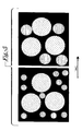
- FIG. 5 is a showing of aggregation and separation of discrete liquid gallium metal droplets so as to achieve the results of the present invention
- FIG. 6 is a photo-micrograph at 100 ⁇ illustrating features of the present invention wherein the presence of liquid gallium alloy accommodates bridging in a silicone oil matrix;
- FIG. 7 illustrates diagrammatically the features of the testing equipment utilized in measuring the thermal performance of devices of the present invention
- FIG. 8 is a flow chart illustrating the steps undertaken in preparation of the compliant pads of the present invention.
- FIG. 9 is an illustration of a typical semiconductor mounted on a hinged heat sink, and having the compliant pad prepared in accordance with the present invention interposed between opposed surfaces of the semiconductor device and heat sink.
- the particulate selected was boron nitride, with the particulate having the normal platelet-like configuration and averaging 40 microns in diameter, and 2 microns in cross-sectional thickness. This particulate is readily wetted by the gallium alloy.
- the BN powder When coated with the liquid gallium alloy, the BN powder did not form hard aggregates, but rather formed a thixotropic paste. This configuration is desirable inasmuch as BN has a high thermal conductivity in the “in-plane” direction, with the conductivity being substantially improved with liquid metal bridging.
- BN has a specific gravity of 2.25 and a thermal conductivity (in-plane) of 350 W-m ⁇ 1 -K ⁇ 1 (orientationally averaged thermal conductivity is reported around 60 W-m ⁇ 1 -K ⁇ 1 ).
- the polymer matrix chosen was a silicone oil with a kinematic viscosity of 100 centistokes, a specific gravity of 0.86 and a thermal conductivity of 0.15 W-m ⁇ 1 -K ⁇ 1 .
- the metal has a specific gravity of 6.5 and a thermal conductivity of 20 W-m ⁇ 1 -K ⁇ 1 .
- the anisotropic platelet BN particles were initially coated with the liquid gallium alloy.
- the liquid metal-to-BN volume ratios were selected in three different ranges as set forth in Table I hereinbelow:
- the coating was accomplished by mechanically mixing the BN powder with the liquid gallium alloy of Example I, and this may be achieved either by hand or in a high-speed mixer. Mixing was followed by addition of the appropriate amount of the silicone oil followed by high-speed mixing until a visually smooth paste was obtained.
- the mixing procedure stabilizes the compound.
- the surface tension of silicone oil is around 20 mN-m ⁇ 1 whereas for the liquid metal it is of the order of 400-500 mN-m ⁇ 1 .
- This means that the spreading coefficient or the ability of silicone oil to wet the surface is far greater than that of a liquid metal.
- the BN particulate is coated with liquid metal prior to contact with silicone oil so as to achieve proper and desirable wetting. Specifically, the following advantages are present:
- the particulate selected was aluminum oxide or alumina, a particulate of spherical symmetry, with a diameter of 3 ⁇ m and a BET surface area of 2 m 2 /g. Both alumina and the alloy were heated to 100° C. (above melt point of Alloy 2) and mixed. When coated with the liquid alloy, the alumina formed a smooth, thixotropic paste. Alumina has a specific gravity of 3.75 and a thermal conductivity 25 W-m ⁇ 1 -K ⁇ 1 .
- the polymer matrix chosen was a silicone oil with a kinematic viscosity of 100 centistokes, a specific gravity of 0.86 and a thermal conductivity of 0.15 W-m ⁇ 1 -K ⁇ 1 .
- the liquid metal has a specific gravity of 7.88 and a thermal conductivity of 25 W-m ⁇ 1 -K ⁇ 1 .
- the alumina particles were initially coated with the alloy.
- the metal-to-alumina volume ratios were selected in three different ranges as set forth in Table II hereinbelow:
- the coating was accomplished by mechanically mixing the alumina powder with the liquid alloy of Example II, and this may be achieved either by hand or in a high-speed mixer. Mixing was followed by addition of the appropriate amount of the silicone oil followed by high-speed mixing until a visually smooth paste was obtained.
- the particulate selected was alumina of Example II. When coated with the liquid gallium alloy, the alumina formed a smooth, thixotropic paste.
- the polymer matrix chosen was a silicone oil with a kinematic viscosity of 100 centistokes, a specific gravity of 0.86 and a thermal conductivity of 0.15 W-m ⁇ 1 -K ⁇ 1 .
- the liquid metal has a specific gravity of 6.5 and a thermal conductivity of 20 W-m ⁇ 1 -K ⁇ 1 .
- the alumina particles were initially coated with the liquid gallium alloy.
- the liquid metal-to-alumina volume ratios were selected in three different ranges as set forth in Table I hereinbelow:
- the coating was accomplished by mechanically mixing the alumina powder with the liquid gallium alloy of Example I, and this may be achieved either by hand or in a high-speed mixer. Mixing was followed by addition of the appropriate amount of the silicone oil followed by high-speed mixing until a visually smooth paste was obtained.
- the formulation 1 (Table I) was tested for thermal conductivity.
- the ASTM D5470 method yielded a thermal conductivity of 8.0 W-m ⁇ 1 -K ⁇ 1 .
- Controlled thermal impedance testing against industry standard materials was also undertaken.
- One of these is a generic thermal interface compound from Dow Corning (DC-340 Thermal grease) and another is a high performance compound made by Shin-Etsu Corporation (G-749 Thermal Grease).
- G-749 Thermal Grease also tested was the gallium liquid metal of Example I.
- the thermal impedance test is shown schematically in FIG. 7.
- the heat spreader was a tin-coated copper plate.
- the heat spreader in turn was coupled to an infinite heat sink, held at 25° C., by DC-340 thermal grease.
- the temperature drop across the interface i.e. temperature difference between transistor case and heat spreader
- the power output was measured and divided by the power output to obtain a thermal impedance in the units of ° C.-W ⁇ 1 .
- FIG. 1 illustrates the manner in which improved contact is obtained between individual coated particulate, particularly BN coated with a liquid gallium alloy.
- the surface characteristics or properties of the composite improve the contact through the formation of liquid bridges.
- This sketch demonstrates the feature of surface wetting of the particulate providing a significant reduction in surface resistivity normally encountered between adjacent particles.
- FIG. 2 illustrates the feature of improved percolation resulting from near-critical packing fraction.
- the surface-to-surface contact as shown in the portion to the left of FIG. 2 is enhanced when a nearcritical packing fraction is achieved through higher concentrations.
- FIG. 3 It is the purpose of FIG. 3 to demonstrate the reduction in aspect ratio achieved with liquid metal coating of particulate. Since boron nitride has an anisotropic platelet structure, its performance in applications contemplated by the present invention are enhanced. With the liquid metal coating, the “effective particle” configuration becomes more ellipsoidal.
- FIG. 4 It is the purpose of FIG. 4 to demonstrate the advantageous feature of the present invention for coating the individual particles, thus lowering viscous dissipation. Improved overall performance can be expected and is accordingly obtained.
- FIG. 5 demonstrates the feature of the present invention wherein individual discrete liquid metal coated particulate will form aggregations or agglomerates, with separation of discrete droplets being achieved when the coated particulate is blended with a polymeric material such as silicone oil. Certain of these features become manifest from the photo-micrograph of FIG. 6 .
- the assembly generally designated 20 includes a heat generating semiconductor device as at 21 mounted upon a suitable or conventional copper base as at 22 .
- a compliant interface made pursuant to the present invention is illustrated at 23 , with the interface being interposed between the opposed surfaces of copper base 22 and heat sink member 24 . Heat flow occurs along the line and in the direction of the indicating arrow.
- FIG. 9 is provided to demonstrate the utilization of the compliant pad of the present invention in connection with a heat generating semiconductor device of conventional configuration.
- the assembly 30 shown in FIG. 9, includes a heat generating semiconductor device or package illustrated at 31 having a heat sink, heat spreader, or other heat dissipating member illustrated at 32 .
- a mechanically compliant pad 33 prepared in accordance with the present invention.
- FIG. 8 is a flow diagram of the steps undertaken in accordance with the creation of compliant pads in accordance with the present invention. As indicated, and as is apparent from the flow diagram, the particulate and alloy are blended until the surfaces of the particulate are thoroughly wetted, and thereafter a paste formulation is prepared through the addition of a liquid polymer.
- BN or alumina particulate can range in size from up to about 1 micron diameter and up to about 40 microns in cross-sectional thickness. It will be observed that the platelet-like configuration of boron nitride in particular provides a highly desirable combination when wetted with liquid metal, with the effective particle being illustrated in FIG. 3 of the drawings. Viscosity control is aided by this feature.
- the silicone oil utilized in the example is a typical liquid silicone, typically VEB 100 (Sivento Inc., previously Huls America), with these materials being, of course, commercially available. Viscosities up to about 1000 centistokes may be satisfactorily utilized.
- One unusual feature of the present invention was electrical resistivity.
- Formulation 1 When Formulation 1 is formed in a pad between opposed surfaces of a semiconductor and a heat sink, the resistivity has been found to be highly significant, having a value of up to about 10 12 ⁇ -cm (Formulation 1, Table I).
Abstract
Description
| Melting | Gallium | Indium | Tin | Bismuth | Zinc | |
| Alloy | Point (° C.) | (%) | (%) | (%) | (%) | (%) |
| 1 | 7 | 61 | 25 | 13 | 0 | 1 |
| TABLE I | ||
| Formulation: | ||
| 1 | 2 | 3 |
| Parts | Volume | Parts | Volume | Parts | Volume | |||
| Material | Wt. | % | Wt. | % | Wt. | % | ||
| BN (40 μm) | 100 | 14 | 0 | 0 | 0 | 0 | ||
| BN (10 μm) | 0 | 0 | 100 | 14 | 100 | 15 | ||
| [Liquid | 1000 | 49 | 1000 | 49 | 800 | 43 | ||
| gallium] | ||||||||
| Alloy 1 {of | ||||||||
| Example I} | ||||||||
| Silicone oil | 100 | 37 | 100 | 37 | 100 | 42 | ||
| Melting | Gallium | Indium | Tin | Bismuth | Zinc | |
| Alloy | Point (° C.) | (%) | (%) | (%) | (%) | (%) |
| 2 | 60 | 0 | 51 | 16.5 | 32.5 | 0 |
| TABLE II | ||
| Formulation: | ||
| 1 | 2 | 3 |
| Parts | Volume | Parts | Volume | Parts | Volume | |||
| Material | Wt. | % | Wt. | % | Wt. | | ||
| Alumina |
| 160 | 15 | 220 | 20 | 375 | 30 | |||
| (3 μm) | ||||||||
| Alloy 2 | 1050 | 45 | 900 | 40 | 800 | 30 | ||
| Silicone oil | 100 | 40 | 100 | 40 | 100 | 40 | ||
| Melting | Gallium | Indium | Tin | Bismuth | Zinc | |
| Alloy | Point (° C.) | (%) | (%) | (%) | (%) | (%) |
| 1 | 7 | 61 | 25 | 13 | 0 | 1 |
| TABLE III | ||
| Formulation: | ||
| 1 | 2 | 3 |
| Parts | Volume | Parts | Volume | Parts | Volume | |||
| Material | Wt. | % | Wt. | % | Wt. | % | ||
| Alumina | 100 | 8 | 150 | 13 | 200 | 18 | ||
| (3 μm) | ||||||||
| Alloy 1 | 1100 | 55 | 1000 | 50 | 900 | 45 | ||
| Silicone oil | 100 | 37 | 100 | 37 | 100 | 37 | ||
| TABLE IV | ||
| Thermal Conductivity | Thermal Impedance | |
| Interface Material | (W-m−1-K−1 | (Normalized) |
| Air | 0.01 | 5-6 |
| Silicone oil | 0.1 | 3 |
| Dow Corning DC-340 | 1.0 | 2 |
| Shin-Etsu [ |
3 | 1 |
| 3.7] G-749 | ||
| Formulation 1 | 8.0 | 0.5-0.6 |
| Liquid metal | 25 | 0.5-0.6 |
Claims (7)
Priority Applications (23)
| Application Number | Priority Date | Filing Date | Title |
|---|---|---|---|
| US09/543,661 US6339120B1 (en) | 2000-04-05 | 2000-04-05 | Method of preparing thermally conductive compounds by liquid metal bridged particle clusters |
| US09/690,994 US6624224B1 (en) | 2000-04-05 | 2000-10-17 | Method of preparing thermally conductive compounds by liquid metal bridged particle clusters |
| DE60132125T DE60132125T2 (en) | 2000-04-05 | 2001-03-30 | Production of thermally conductive substances by liquid-metal-bridged particle groups |
| EP01303104A EP1143511B1 (en) | 2000-04-05 | 2001-03-30 | Method of preparing thermally conductive compounds by liquid metal bridged particle clusters |
| ES01303105T ES2163380T1 (en) | 2000-04-05 | 2001-03-30 | METHOD OF PREPARATION OF HEAT-CONDUCTING COMBINATIONS THROUGH CONGLOMERATES OF LIQUID FILLED METAL PARTICLES. |
| DE1143511T DE1143511T1 (en) | 2000-04-05 | 2001-03-30 | Preparation of thermally conductive substances by liquid metal bridged particle groups |
| DE1143512T DE1143512T1 (en) | 2000-04-05 | 2001-03-30 | Preparation of thermally conductive substances by liquid metal bridged particle groups |
| TR2001/03156T TR200103156T3 (en) | 2000-04-05 | 2001-03-30 | Thermally conductive through liquid metal bridged clusters Method of preparing thermally conductive compounds through liquid metal bridged clusters. method of preparing compounds. |
| AT01303105T ATE387722T1 (en) | 2000-04-05 | 2001-03-30 | PRODUCTION OF THERMALLY CONDUCTIVE MATERIALS USING LIQUID METAL-BRIDGED PARTICLE GROUPS |
| EP01303105A EP1143512B1 (en) | 2000-04-05 | 2001-03-30 | Method of preparing thermally conductive compounds by liquid metal bridged particle clusters |
| ES01303104T ES2161659T1 (en) | 2000-04-05 | 2001-03-30 | METHOD OF PREPARATION OF HEAT-CONDUCTING COMBINATIONS THROUGH CONGLOMERATES OF LIQUID FILLED METAL PARTICLES. |
| DE60132943T DE60132943T2 (en) | 2000-04-05 | 2001-03-30 | Production of thermally conductive substances by liquid-metal-bridged particle groups |
| AT01303104T ATE382954T1 (en) | 2000-04-05 | 2001-03-30 | PRODUCTION OF THERMALLY CONDUCTIVE MATERIALS USING LIQUID METAL-BRIDGED PARTICLE GROUPS |
| CA002343504A CA2343504A1 (en) | 2000-04-05 | 2001-04-03 | Method of preparing thermally conductive compounds by liquid metal bridged particle clusters |
| TW090107990A TW583227B (en) | 2000-04-05 | 2001-04-03 | Method of preparing thermally conductive compounds by liquid metal bridged particle clusters |
| TW090107997A TW591776B (en) | 2000-04-05 | 2001-04-03 | Method of preparing thermally conductive compounds by liquid metal bridged particle clusters |
| JP2001107064A JP2001329068A (en) | 2000-04-05 | 2001-04-05 | Manufacturing method of thermal conductive compound by crosslinking particle cluster of liquid metal |
| US09/946,879 US6797758B2 (en) | 2000-04-05 | 2001-09-05 | Morphing fillers and thermal interface materials |
| GR20010300073T GR20010300073T1 (en) | 2000-04-05 | 2001-12-31 | Method of preparing thermally conductive compounds by liquid metal bridged particle clusters |
| GR20010300070T GR20010300070T1 (en) | 2000-04-05 | 2001-12-31 | Method of preparing thermally conductive compounds by liquid metal bridged particle clusters |
| US10/279,593 US6984685B2 (en) | 2000-04-05 | 2002-10-24 | Thermal interface pad utilizing low melting metal with retention matrix |
| TW92119419A TWI265947B (en) | 2000-04-05 | 2003-07-16 | Thermal interface pad utilizing low melting metal with retention matrix |
| US11/122,210 USRE39992E1 (en) | 2000-04-05 | 2005-05-04 | Morphing fillers and thermal interface materials |
Applications Claiming Priority (1)
| Application Number | Priority Date | Filing Date | Title |
|---|---|---|---|
| US09/543,661 US6339120B1 (en) | 2000-04-05 | 2000-04-05 | Method of preparing thermally conductive compounds by liquid metal bridged particle clusters |
Related Parent Applications (2)
| Application Number | Title | Priority Date | Filing Date |
|---|---|---|---|
| US09/690,994 Continuation-In-Part US6624224B1 (en) | 2000-04-05 | 2000-10-17 | Method of preparing thermally conductive compounds by liquid metal bridged particle clusters |
| US09/865,778 Continuation-In-Part US6649325B1 (en) | 2000-04-05 | 2001-05-25 | Thermally conductive dielectric mounts for printed circuitry and semi-conductor devices and method of preparation |
Related Child Applications (2)
| Application Number | Title | Priority Date | Filing Date |
|---|---|---|---|
| US09/690,994 Continuation-In-Part US6624224B1 (en) | 2000-04-05 | 2000-10-17 | Method of preparing thermally conductive compounds by liquid metal bridged particle clusters |
| US09/946,879 Continuation-In-Part US6797758B2 (en) | 2000-04-05 | 2001-09-05 | Morphing fillers and thermal interface materials |
Publications (1)
| Publication Number | Publication Date |
|---|---|
| US6339120B1 true US6339120B1 (en) | 2002-01-15 |
Family
ID=24169008
Family Applications (3)
| Application Number | Title | Priority Date | Filing Date |
|---|---|---|---|
| US09/543,661 Expired - Lifetime US6339120B1 (en) | 2000-04-05 | 2000-04-05 | Method of preparing thermally conductive compounds by liquid metal bridged particle clusters |
| US09/690,994 Expired - Lifetime US6624224B1 (en) | 2000-04-05 | 2000-10-17 | Method of preparing thermally conductive compounds by liquid metal bridged particle clusters |
| US11/122,210 Expired - Lifetime USRE39992E1 (en) | 2000-04-05 | 2005-05-04 | Morphing fillers and thermal interface materials |
Family Applications After (2)
| Application Number | Title | Priority Date | Filing Date |
|---|---|---|---|
| US09/690,994 Expired - Lifetime US6624224B1 (en) | 2000-04-05 | 2000-10-17 | Method of preparing thermally conductive compounds by liquid metal bridged particle clusters |
| US11/122,210 Expired - Lifetime USRE39992E1 (en) | 2000-04-05 | 2005-05-04 | Morphing fillers and thermal interface materials |
Country Status (10)
| Country | Link |
|---|---|
| US (3) | US6339120B1 (en) |
| EP (1) | EP1143512B1 (en) |
| JP (1) | JP2001329068A (en) |
| AT (1) | ATE387722T1 (en) |
| CA (1) | CA2343504A1 (en) |
| DE (3) | DE1143512T1 (en) |
| ES (1) | ES2163380T1 (en) |
| GR (1) | GR20010300073T1 (en) |
| TR (1) | TR200103156T3 (en) |
| TW (1) | TW591776B (en) |
Cited By (34)
| Publication number | Priority date | Publication date | Assignee | Title |
|---|---|---|---|---|
| US20030027910A1 (en) * | 2000-04-05 | 2003-02-06 | The Bergquist Company | Morphing fillers and thermal interface materials |
| US20030152764A1 (en) * | 2002-02-06 | 2003-08-14 | Bunyan Michael H. | Thermal management materials having a phase change dispersion |
| US6624224B1 (en) * | 2000-04-05 | 2003-09-23 | The Bergquist Company | Method of preparing thermally conductive compounds by liquid metal bridged particle clusters |
| US20030178730A1 (en) * | 2002-02-08 | 2003-09-25 | Rumer Christopher L. | Integrated heat spreader, heat sink or heat pipe with pre-attached phase change thermal interface material and method of making an electronic assembly |
| US20030187116A1 (en) * | 2000-04-05 | 2003-10-02 | The Bergquist Company | Thermal interface pad utilizing low melting metal with retention matrix |
| US20030203188A1 (en) * | 2002-02-06 | 2003-10-30 | H. Bunyan Michael | Thermal management materials |
| US20040052050A1 (en) * | 2002-09-18 | 2004-03-18 | Koning Paul A. | Polymer solder hybrid |
| US20040120120A1 (en) * | 2002-12-24 | 2004-06-24 | Louis Soto | Multi-layer laminated structures, method for fabricating such structures, and power supply including such structures |
| US20040120129A1 (en) * | 2002-12-24 | 2004-06-24 | Louis Soto | Multi-layer laminated structures for mounting electrical devices and method for fabricating such structures |
| US20040151885A1 (en) * | 2003-02-04 | 2004-08-05 | Saikumar Jayaraman | Polymer matrices for polymer solder hybrid materials |
| US20050077618A1 (en) * | 2002-12-19 | 2005-04-14 | 3M Innovative Properties Company | Flexible heat sink |
| US20050212122A1 (en) * | 2004-03-25 | 2005-09-29 | Duggan Michael R | Multi-layer fet array and method of fabricating |
| US20050228097A1 (en) * | 2004-03-30 | 2005-10-13 | General Electric Company | Thermally conductive compositions and methods of making thereof |
| US7147367B2 (en) * | 2002-06-11 | 2006-12-12 | Saint-Gobain Performance Plastics Corporation | Thermal interface material with low melting alloy |
| US20070048520A1 (en) * | 2005-08-26 | 2007-03-01 | Hon Hai Precision Industry Co., Ltd. | Thermal interface material and method for making the same |
| US20110038124A1 (en) * | 2008-04-21 | 2011-02-17 | Honeywell International Inc. | Thermal interconnect and interface materials, methods of production and uses thereof |
| US20110220704A1 (en) * | 2010-03-09 | 2011-09-15 | Weiping Liu | Composite solder alloy preform |
| US20130000117A1 (en) * | 2011-06-30 | 2013-01-03 | Rajashree Baskaran | Liquid metal interconnects |
| US9831211B2 (en) | 2015-08-31 | 2017-11-28 | Samsung Electronics Co., Ltd. | Anisotropic conductive material, electronic device including anisotropic conductive material, and method of manufacturing electronic device |
| CN107501953A (en) * | 2017-09-20 | 2017-12-22 | 天津沃尔提莫新材料技术股份有限公司 | A kind of heat-conducting silicone grease of the filler containing liquid metal for conducting heat |
| US10155894B2 (en) | 2014-07-07 | 2018-12-18 | Honeywell International Inc. | Thermal interface material with ion scavenger |
| US10174433B2 (en) | 2013-12-05 | 2019-01-08 | Honeywell International Inc. | Stannous methanesulfonate solution with adjusted pH |
| US10287471B2 (en) | 2014-12-05 | 2019-05-14 | Honeywell International Inc. | High performance thermal interface materials with low thermal impedance |
| US10312177B2 (en) | 2015-11-17 | 2019-06-04 | Honeywell International Inc. | Thermal interface materials including a coloring agent |
| US10428256B2 (en) | 2017-10-23 | 2019-10-01 | Honeywell International Inc. | Releasable thermal gel |
| US10453773B2 (en) | 2015-09-11 | 2019-10-22 | Laird Technologies, Inc. | Devices for absorbing energy from electronic components |
| US10501671B2 (en) | 2016-07-26 | 2019-12-10 | Honeywell International Inc. | Gel-type thermal interface material |
| US10781349B2 (en) | 2016-03-08 | 2020-09-22 | Honeywell International Inc. | Thermal interface material including crosslinker and multiple fillers |
| US11041103B2 (en) | 2017-09-08 | 2021-06-22 | Honeywell International Inc. | Silicone-free thermal gel |
| US11072706B2 (en) | 2018-02-15 | 2021-07-27 | Honeywell International Inc. | Gel-type thermal interface material |
| US20210410283A1 (en) * | 2020-06-24 | 2021-12-30 | Yale University | Biphasic material and stretchable circuit board |
| US11373921B2 (en) | 2019-04-23 | 2022-06-28 | Honeywell International Inc. | Gel-type thermal interface material with low pre-curing viscosity and elastic properties post-curing |
| CN115197677A (en) * | 2022-07-27 | 2022-10-18 | 空间液金技术研究(昆山)有限公司 | Thermal interface material with phase change function, preparation method and application thereof |
| CN115725185A (en) * | 2022-12-20 | 2023-03-03 | 深圳先进电子材料国际创新研究院 | Thermal interface material based on liquid metal bridging aluminum powder and preparation method thereof |
Families Citing this family (26)
| Publication number | Priority date | Publication date | Assignee | Title |
|---|---|---|---|---|
| US7311967B2 (en) * | 2001-10-18 | 2007-12-25 | Intel Corporation | Thermal interface material and electronic assembly having such a thermal interface material |
| JP2003201528A (en) * | 2001-10-26 | 2003-07-18 | Ngk Insulators Ltd | Heat sink material |
| GB2395360B (en) * | 2001-10-26 | 2005-03-16 | Ngk Insulators Ltd | Heat sink material |
| US6703128B2 (en) * | 2002-02-15 | 2004-03-09 | Delphi Technologies, Inc. | Thermally-capacitive phase change encapsulant for electronic devices |
| US6787899B2 (en) * | 2002-03-12 | 2004-09-07 | Intel Corporation | Electronic assemblies with solidified thixotropic thermal interface material |
| JP4551074B2 (en) * | 2003-10-07 | 2010-09-22 | 信越化学工業株式会社 | Curable organopolysiloxane composition and semiconductor device |
| JP5305656B2 (en) * | 2004-08-23 | 2013-10-02 | モーメンティブ・パフォーマンス・マテリアルズ・インク | Thermally conductive composition and method for producing the same |
| US7351360B2 (en) | 2004-11-12 | 2008-04-01 | International Business Machines Corporation | Self orienting micro plates of thermally conducting material as component in thermal paste or adhesive |
| US7259580B2 (en) * | 2005-02-22 | 2007-08-21 | International Business Machines Corporation | Method and apparatus for temporary thermal coupling of an electronic device to a heat sink during test |
| CN101351755B (en) * | 2006-03-28 | 2013-08-14 | 派克汉尼芬公司 | Dispensable cured resin |
| US7527859B2 (en) * | 2006-10-08 | 2009-05-05 | Momentive Performance Materials Inc. | Enhanced boron nitride composition and compositions made therewith |
| WO2009035907A2 (en) * | 2007-09-11 | 2009-03-19 | Dow Corning Corporation | Thermal interface material, electronic device containing the thermal interface material, and methods for their preparation and use |
| KR20100075894A (en) * | 2007-09-11 | 2010-07-05 | 다우 코닝 코포레이션 | Composite, thermal interface material containing the composite, and methods for their preparation and use |
| JP4840416B2 (en) * | 2008-07-22 | 2011-12-21 | 富士通株式会社 | Manufacturing method of semiconductor device |
| JP4913874B2 (en) * | 2010-01-18 | 2012-04-11 | 信越化学工業株式会社 | Curable organopolysiloxane composition and semiconductor device |
| JP5565758B2 (en) * | 2011-06-29 | 2014-08-06 | 信越化学工業株式会社 | Curable, grease-like thermally conductive silicone composition and semiconductor device |
| EP3105300B1 (en) | 2014-02-13 | 2019-08-21 | Honeywell International Inc. | Compressible thermal interface materials |
| KR20180062243A (en) * | 2016-11-30 | 2018-06-08 | 삼성전자주식회사 | Paste material, interconnection element formed from paste material and electronic device including interconnection element |
| DE102017116931B4 (en) | 2017-07-26 | 2021-01-14 | Deutsches Zentrum für Luft- und Raumfahrt e.V. | Repair device and method of making a repair device |
| CN112449546A (en) * | 2019-08-27 | 2021-03-05 | 华硕电脑股份有限公司 | Liquid metal radiating paste coating method and radiating module |
| TWI698287B (en) | 2019-08-27 | 2020-07-11 | 華碩電腦股份有限公司 | Method of coating liquid metal heat-dissipatng paste and heat-dissipatng module using liquid metal heat-dissipatng paste |
| DE102019123950A1 (en) | 2019-09-06 | 2021-03-11 | Deutsches Zentrum für Luft- und Raumfahrt e.V. | Tool device with a heating mat and repair methods and manufacturing methods for workpieces made of plastic material |
| DE102019123952A1 (en) | 2019-09-06 | 2021-03-11 | Deutsches Zentrum für Luft- und Raumfahrt e.V. | Heating mat |
| CN113491584B (en) * | 2020-03-20 | 2022-08-02 | 北京梦之墨科技有限公司 | Liquid metal flexible patch for CT positioning and preparation method thereof |
| CN111589464B (en) * | 2020-04-23 | 2023-03-31 | 台州学院 | Boron nitride-loaded rhodium-gallium-tin liquid alloy catalyst and preparation method and application thereof |
| KR20220016680A (en) | 2020-08-03 | 2022-02-10 | 삼성전자주식회사 | Thermal interface material, method of manufacturing the same, and semiconductor package including the same |
Citations (17)
| Publication number | Priority date | Publication date | Assignee | Title |
|---|---|---|---|---|
| US3226608A (en) | 1959-06-24 | 1965-12-28 | Gen Electric | Liquid metal electrical connection |
| US3248615A (en) | 1963-05-13 | 1966-04-26 | Bbc Brown Boveri & Cie | Semiconductor device with liquidized solder layer for compensation of expansion stresses |
| US4129881A (en) | 1976-03-18 | 1978-12-12 | Ckd Praha, Oborovy Podnik | Heat sink cooled, semiconductor device assembly having liquid metal interface |
| US4147669A (en) | 1977-03-28 | 1979-04-03 | Rockwell International Corporation | Conductive adhesive for providing electrical and thermal conductivity |
| US4233103A (en) | 1978-12-20 | 1980-11-11 | The United States Of America As Represented By The Secretary Of The Air Force | High temperature-resistant conductive adhesive and method employing same |
| US4254431A (en) | 1979-06-20 | 1981-03-03 | International Business Machines Corporation | Restorable backbond for LSI chips using liquid metal coated dendrites |
| US4323914A (en) | 1979-02-01 | 1982-04-06 | International Business Machines Corporation | Heat transfer structure for integrated circuit package |
| US4398975A (en) | 1980-12-25 | 1983-08-16 | Sony Corporation | Conductive paste |
| US5012858A (en) | 1986-10-20 | 1991-05-07 | Fujitsu Limited | Method of cooling a semiconductor device with a cooling unit, using metal sherbet between the device and the cooling unit |
| US5053195A (en) | 1989-07-19 | 1991-10-01 | Microelectronics And Computer Technology Corp. | Bonding amalgam and method of making |
| US5056706A (en) | 1989-11-20 | 1991-10-15 | Microelectronics And Computer Technology Corporation | Liquid metal paste for thermal and electrical connections |
| US5170930A (en) | 1991-11-14 | 1992-12-15 | Microelectronics And Computer Technology Corporation | Liquid metal paste for thermal and electrical connections |
| US5173256A (en) | 1989-08-03 | 1992-12-22 | International Business Machines Corporation | Liquid metal matrix thermal paste |
| US5198189A (en) | 1989-08-03 | 1993-03-30 | International Business Machines Corporation | Liquid metal matrix thermal paste |
| US5225157A (en) | 1989-07-19 | 1993-07-06 | Microelectronics And Computer Technology Corporation | Amalgam composition for room temperature bonding |
| US5328087A (en) | 1993-03-29 | 1994-07-12 | Microelectronics And Computer Technology Corporation | Thermally and electrically conductive adhesive material and method of bonding with same |
| US5445308A (en) | 1993-03-29 | 1995-08-29 | Nelson; Richard D. | Thermally conductive connection with matrix material and randomly dispersed filler containing liquid metal |
Family Cites Families (14)
| Publication number | Priority date | Publication date | Assignee | Title |
|---|---|---|---|---|
| US3793106A (en) | 1969-12-31 | 1974-02-19 | Macdermid Inc | Process for forming plastic parts having surfaces receptive to adherent coatings |
| US4520067A (en) | 1982-06-23 | 1985-05-28 | Union Carbide Corporation | Composition useful for making circuit board substrates and electrical connectors |
| US4550140A (en) | 1984-03-20 | 1985-10-29 | Union Carbide Corporation | Circuit board substrates prepared from poly(aryl ethers)s |
| DE3700902A1 (en) | 1986-01-14 | 1987-07-16 | Mitsubishi Gas Chemical Co | METHOD OF MANUFACTURING PLASTIC MOLDED PRINTED CIRCUIT PANELS |
| US5538789A (en) | 1990-02-09 | 1996-07-23 | Toranaga Technologies, Inc. | Composite substrates for preparation of printed circuits |
| US5548034A (en) | 1992-07-31 | 1996-08-20 | International Business Machines Corporation | Modified dicyanate ester resins having enhanced fracture toughness |
| DE69328687D1 (en) * | 1993-07-06 | 2000-06-21 | Toshiba Kawasaki Kk | HEAT-CONDUCTING PLATE |
| US5827907A (en) | 1993-08-30 | 1998-10-27 | Ibm Corporation | Homo-, co- or multicomponent thermoplastic polymer dispersed in a thermoset resin |
| JPH0853664A (en) * | 1994-08-10 | 1996-02-27 | Fujitsu Ltd | Thermally conductive material and its production, method for cooling electronic part, method for cooling circuit board, and method for mounting electronic part |
| TW340132B (en) * | 1994-10-20 | 1998-09-11 | Ibm | Structure for use as an electrical interconnection means and process for preparing the same |
| US5958590A (en) * | 1995-03-31 | 1999-09-28 | International Business Machines Corporation | Dendritic powder materials for high conductivity paste applications |
| US5950066A (en) * | 1996-06-14 | 1999-09-07 | The Bergquist Company | Semisolid thermal interface with low flow resistance |
| US6339120B1 (en) * | 2000-04-05 | 2002-01-15 | The Bergquist Company | Method of preparing thermally conductive compounds by liquid metal bridged particle clusters |
| US6649325B1 (en) | 2001-05-25 | 2003-11-18 | The Bergquist Company | Thermally conductive dielectric mounts for printed circuitry and semi-conductor devices and method of preparation |
-
2000
- 2000-04-05 US US09/543,661 patent/US6339120B1/en not_active Expired - Lifetime
- 2000-10-17 US US09/690,994 patent/US6624224B1/en not_active Expired - Lifetime
-
2001
- 2001-03-30 DE DE1143512T patent/DE1143512T1/en active Pending
- 2001-03-30 EP EP01303105A patent/EP1143512B1/en not_active Expired - Lifetime
- 2001-03-30 ES ES01303105T patent/ES2163380T1/en active Pending
- 2001-03-30 AT AT01303105T patent/ATE387722T1/en not_active IP Right Cessation
- 2001-03-30 DE DE60132125T patent/DE60132125T2/en not_active Expired - Lifetime
- 2001-03-30 DE DE60132943T patent/DE60132943T2/en not_active Expired - Lifetime
- 2001-03-30 TR TR2001/03156T patent/TR200103156T3/en unknown
- 2001-04-03 TW TW090107997A patent/TW591776B/en not_active IP Right Cessation
- 2001-04-03 CA CA002343504A patent/CA2343504A1/en not_active Abandoned
- 2001-04-05 JP JP2001107064A patent/JP2001329068A/en active Pending
- 2001-12-31 GR GR20010300073T patent/GR20010300073T1/en unknown
-
2005
- 2005-05-04 US US11/122,210 patent/USRE39992E1/en not_active Expired - Lifetime
Patent Citations (18)
| Publication number | Priority date | Publication date | Assignee | Title |
|---|---|---|---|---|
| US3226608A (en) | 1959-06-24 | 1965-12-28 | Gen Electric | Liquid metal electrical connection |
| US3248615A (en) | 1963-05-13 | 1966-04-26 | Bbc Brown Boveri & Cie | Semiconductor device with liquidized solder layer for compensation of expansion stresses |
| US4129881A (en) | 1976-03-18 | 1978-12-12 | Ckd Praha, Oborovy Podnik | Heat sink cooled, semiconductor device assembly having liquid metal interface |
| US4147669A (en) | 1977-03-28 | 1979-04-03 | Rockwell International Corporation | Conductive adhesive for providing electrical and thermal conductivity |
| US4233103A (en) | 1978-12-20 | 1980-11-11 | The United States Of America As Represented By The Secretary Of The Air Force | High temperature-resistant conductive adhesive and method employing same |
| US4323914A (en) | 1979-02-01 | 1982-04-06 | International Business Machines Corporation | Heat transfer structure for integrated circuit package |
| US4254431A (en) | 1979-06-20 | 1981-03-03 | International Business Machines Corporation | Restorable backbond for LSI chips using liquid metal coated dendrites |
| US4398975A (en) | 1980-12-25 | 1983-08-16 | Sony Corporation | Conductive paste |
| US5012858A (en) | 1986-10-20 | 1991-05-07 | Fujitsu Limited | Method of cooling a semiconductor device with a cooling unit, using metal sherbet between the device and the cooling unit |
| US5024264A (en) | 1986-10-20 | 1991-06-18 | Fujitsu Limited | Method of cooling a semiconductor device with a cooling unit, using metal sherbet between the device and the cooling unit |
| US5053195A (en) | 1989-07-19 | 1991-10-01 | Microelectronics And Computer Technology Corp. | Bonding amalgam and method of making |
| US5225157A (en) | 1989-07-19 | 1993-07-06 | Microelectronics And Computer Technology Corporation | Amalgam composition for room temperature bonding |
| US5173256A (en) | 1989-08-03 | 1992-12-22 | International Business Machines Corporation | Liquid metal matrix thermal paste |
| US5198189A (en) | 1989-08-03 | 1993-03-30 | International Business Machines Corporation | Liquid metal matrix thermal paste |
| US5056706A (en) | 1989-11-20 | 1991-10-15 | Microelectronics And Computer Technology Corporation | Liquid metal paste for thermal and electrical connections |
| US5170930A (en) | 1991-11-14 | 1992-12-15 | Microelectronics And Computer Technology Corporation | Liquid metal paste for thermal and electrical connections |
| US5328087A (en) | 1993-03-29 | 1994-07-12 | Microelectronics And Computer Technology Corporation | Thermally and electrically conductive adhesive material and method of bonding with same |
| US5445308A (en) | 1993-03-29 | 1995-08-29 | Nelson; Richard D. | Thermally conductive connection with matrix material and randomly dispersed filler containing liquid metal |
Non-Patent Citations (4)
| Title |
|---|
| Harman, "Hard Gallium Alloys for Use as Low Contact Resistance Electrodes and for Bonding Thermocouples into Samples", The Review of Scientific Instruments, Jul. 1960, vol. 31, No. 7, pp. 717-720. |
| IBM Technical Disclosure Bulletin, vol. 19, No. 8, Jan. 1977 "Thermal Enchancement of Modules", E. B. Hultmark et al. |
| IBM Technical Disclosure Bulletin, vol. 20, No. 11B, Apr. 1978 "Electronic Packaging Structure", A. J. Arnold et al., pp. 4820-4822. |
| IBM Technical Disclosure Bulletin, vol. 20, No. 11B, Apr. 1978 "Liquid-Metal-Cooled Integrated Circuit Module Structures", E. Berndlmaier et al. pp. 4817 and 4818. |
Cited By (57)
| Publication number | Priority date | Publication date | Assignee | Title |
|---|---|---|---|---|
| USRE39992E1 (en) * | 2000-04-05 | 2008-01-01 | The Bergquist Company | Morphing fillers and thermal interface materials |
| US6984685B2 (en) * | 2000-04-05 | 2006-01-10 | The Bergquist Company | Thermal interface pad utilizing low melting metal with retention matrix |
| US6624224B1 (en) * | 2000-04-05 | 2003-09-23 | The Bergquist Company | Method of preparing thermally conductive compounds by liquid metal bridged particle clusters |
| US20030187116A1 (en) * | 2000-04-05 | 2003-10-02 | The Bergquist Company | Thermal interface pad utilizing low melting metal with retention matrix |
| US20030027910A1 (en) * | 2000-04-05 | 2003-02-06 | The Bergquist Company | Morphing fillers and thermal interface materials |
| US6797758B2 (en) * | 2000-04-05 | 2004-09-28 | The Bergquist Company | Morphing fillers and thermal interface materials |
| US7682690B2 (en) | 2002-02-06 | 2010-03-23 | Parker-Hannifin Corporation | Thermal management materials having a phase change dispersion |
| US20030203188A1 (en) * | 2002-02-06 | 2003-10-30 | H. Bunyan Michael | Thermal management materials |
| US20030152764A1 (en) * | 2002-02-06 | 2003-08-14 | Bunyan Michael H. | Thermal management materials having a phase change dispersion |
| US6946190B2 (en) | 2002-02-06 | 2005-09-20 | Parker-Hannifin Corporation | Thermal management materials |
| US20030178730A1 (en) * | 2002-02-08 | 2003-09-25 | Rumer Christopher L. | Integrated heat spreader, heat sink or heat pipe with pre-attached phase change thermal interface material and method of making an electronic assembly |
| US7147367B2 (en) * | 2002-06-11 | 2006-12-12 | Saint-Gobain Performance Plastics Corporation | Thermal interface material with low melting alloy |
| US20040052050A1 (en) * | 2002-09-18 | 2004-03-18 | Koning Paul A. | Polymer solder hybrid |
| US6813153B2 (en) | 2002-09-18 | 2004-11-02 | Intel Corporation | Polymer solder hybrid |
| US20050077618A1 (en) * | 2002-12-19 | 2005-04-14 | 3M Innovative Properties Company | Flexible heat sink |
| US7399919B2 (en) * | 2002-12-19 | 2008-07-15 | 3M Innovative Properties Company | Flexible heat sink |
| US20040120129A1 (en) * | 2002-12-24 | 2004-06-24 | Louis Soto | Multi-layer laminated structures for mounting electrical devices and method for fabricating such structures |
| US6831835B2 (en) | 2002-12-24 | 2004-12-14 | Ault, Inc. | Multi-layer laminated structures, method for fabricating such structures, and power supply including such structures |
| US20040120120A1 (en) * | 2002-12-24 | 2004-06-24 | Louis Soto | Multi-layer laminated structures, method for fabricating such structures, and power supply including such structures |
| US20110194254A1 (en) * | 2003-02-04 | 2011-08-11 | Saikumar Jayaraman | Polymer matrices for polymer solder hybrid materials |
| US8703286B2 (en) | 2003-02-04 | 2014-04-22 | Intel Corporation | Polymer matrices for polymer solder hybrid materials |
| US7252877B2 (en) * | 2003-02-04 | 2007-08-07 | Intel Corporation | Polymer matrices for polymer solder hybrid materials |
| US20070251639A1 (en) * | 2003-02-04 | 2007-11-01 | Saikumar Jayaraman | Polymer matrices for polymer solder hybrid materials |
| US9247686B2 (en) * | 2003-02-04 | 2016-01-26 | Intel Corporation | Polymer matrices for polymer solder hybrid materials |
| US20140182763A1 (en) * | 2003-02-04 | 2014-07-03 | Saikumar Jayaraman | Polymer matrices for polymer solder hybrid materials |
| US20040151885A1 (en) * | 2003-02-04 | 2004-08-05 | Saikumar Jayaraman | Polymer matrices for polymer solder hybrid materials |
| US7967942B2 (en) | 2003-02-04 | 2011-06-28 | Intel Corporation | Polymer matrices for polymer solder hybrid materials |
| US20050212122A1 (en) * | 2004-03-25 | 2005-09-29 | Duggan Michael R | Multi-layer fet array and method of fabricating |
| US7193307B2 (en) | 2004-03-25 | 2007-03-20 | Ault Incorporated | Multi-layer FET array and method of fabricating |
| US20050228097A1 (en) * | 2004-03-30 | 2005-10-13 | General Electric Company | Thermally conductive compositions and methods of making thereof |
| US20070048520A1 (en) * | 2005-08-26 | 2007-03-01 | Hon Hai Precision Industry Co., Ltd. | Thermal interface material and method for making the same |
| US20110038124A1 (en) * | 2008-04-21 | 2011-02-17 | Honeywell International Inc. | Thermal interconnect and interface materials, methods of production and uses thereof |
| US20110220704A1 (en) * | 2010-03-09 | 2011-09-15 | Weiping Liu | Composite solder alloy preform |
| US8348139B2 (en) | 2010-03-09 | 2013-01-08 | Indium Corporation | Composite solder alloy preform |
| US20130000117A1 (en) * | 2011-06-30 | 2013-01-03 | Rajashree Baskaran | Liquid metal interconnects |
| US9835648B2 (en) * | 2011-06-30 | 2017-12-05 | Intel Corporation | Liquid metal interconnects |
| US10174433B2 (en) | 2013-12-05 | 2019-01-08 | Honeywell International Inc. | Stannous methanesulfonate solution with adjusted pH |
| US10155894B2 (en) | 2014-07-07 | 2018-12-18 | Honeywell International Inc. | Thermal interface material with ion scavenger |
| US10428257B2 (en) | 2014-07-07 | 2019-10-01 | Honeywell International Inc. | Thermal interface material with ion scavenger |
| US10287471B2 (en) | 2014-12-05 | 2019-05-14 | Honeywell International Inc. | High performance thermal interface materials with low thermal impedance |
| US9831211B2 (en) | 2015-08-31 | 2017-11-28 | Samsung Electronics Co., Ltd. | Anisotropic conductive material, electronic device including anisotropic conductive material, and method of manufacturing electronic device |
| US10453773B2 (en) | 2015-09-11 | 2019-10-22 | Laird Technologies, Inc. | Devices for absorbing energy from electronic components |
| US10978369B2 (en) | 2015-09-11 | 2021-04-13 | Laird Technologies, Inc. | Devices for absorbing energy from electronic components |
| US10312177B2 (en) | 2015-11-17 | 2019-06-04 | Honeywell International Inc. | Thermal interface materials including a coloring agent |
| US10781349B2 (en) | 2016-03-08 | 2020-09-22 | Honeywell International Inc. | Thermal interface material including crosslinker and multiple fillers |
| US10501671B2 (en) | 2016-07-26 | 2019-12-10 | Honeywell International Inc. | Gel-type thermal interface material |
| US11041103B2 (en) | 2017-09-08 | 2021-06-22 | Honeywell International Inc. | Silicone-free thermal gel |
| CN107501953B (en) * | 2017-09-20 | 2023-03-10 | 深圳沃尔提莫电子材料有限公司 | Heat-conducting silicone grease containing liquid metal heat-conducting filler |
| CN107501953A (en) * | 2017-09-20 | 2017-12-22 | 天津沃尔提莫新材料技术股份有限公司 | A kind of heat-conducting silicone grease of the filler containing liquid metal for conducting heat |
| US10428256B2 (en) | 2017-10-23 | 2019-10-01 | Honeywell International Inc. | Releasable thermal gel |
| US11072706B2 (en) | 2018-02-15 | 2021-07-27 | Honeywell International Inc. | Gel-type thermal interface material |
| US11373921B2 (en) | 2019-04-23 | 2022-06-28 | Honeywell International Inc. | Gel-type thermal interface material with low pre-curing viscosity and elastic properties post-curing |
| US20210410283A1 (en) * | 2020-06-24 | 2021-12-30 | Yale University | Biphasic material and stretchable circuit board |
| US11937372B2 (en) * | 2020-06-24 | 2024-03-19 | Yale University | Biphasic material and stretchable circuit board |
| CN115197677A (en) * | 2022-07-27 | 2022-10-18 | 空间液金技术研究(昆山)有限公司 | Thermal interface material with phase change function, preparation method and application thereof |
| CN115725185A (en) * | 2022-12-20 | 2023-03-03 | 深圳先进电子材料国际创新研究院 | Thermal interface material based on liquid metal bridging aluminum powder and preparation method thereof |
| CN115725185B (en) * | 2022-12-20 | 2024-03-15 | 深圳先进电子材料国际创新研究院 | Thermal interface material based on liquid metal bridging aluminum powder and preparation method thereof |
Also Published As
| Publication number | Publication date |
|---|---|
| GR20010300073T1 (en) | 2001-12-31 |
| EP1143512A2 (en) | 2001-10-10 |
| JP2001329068A (en) | 2001-11-27 |
| TW591776B (en) | 2004-06-11 |
| EP1143512B1 (en) | 2008-02-27 |
| EP1143512A3 (en) | 2004-10-06 |
| DE1143512T1 (en) | 2002-04-18 |
| CA2343504A1 (en) | 2001-10-05 |
| DE60132125D1 (en) | 2008-02-14 |
| TR200103156T3 (en) | 2002-01-21 |
| DE60132943T2 (en) | 2009-02-26 |
| US6624224B1 (en) | 2003-09-23 |
| DE60132943D1 (en) | 2008-04-10 |
| ES2163380T1 (en) | 2002-02-01 |
| DE60132125T2 (en) | 2008-12-18 |
| USRE39992E1 (en) | 2008-01-01 |
| ATE387722T1 (en) | 2008-03-15 |
Similar Documents
| Publication | Publication Date | Title |
|---|---|---|
| US6339120B1 (en) | Method of preparing thermally conductive compounds by liquid metal bridged particle clusters | |
| CA2401299C (en) | Morphing fillers and thermal interface materials | |
| US6984685B2 (en) | Thermal interface pad utilizing low melting metal with retention matrix | |
| US5056706A (en) | Liquid metal paste for thermal and electrical connections | |
| US6841867B2 (en) | Gel thermal interface materials comprising fillers having low melting point and electronic packages comprising these gel thermal interface materials | |
| US6284817B1 (en) | Conductive, resin-based compositions | |
| MXPA03009363A (en) | Phase change thermal interface composition having induced bonding property. | |
| EP1143511B1 (en) | Method of preparing thermally conductive compounds by liquid metal bridged particle clusters | |
| CN108129841A (en) | A kind of liquid metal insulating heat-conduction material and preparation method thereof | |
| US20020140082A1 (en) | Chain extension for thermal materials | |
| JP2002532914A (en) | Method of applying phase change thermal interface material | |
| EP0696630A2 (en) | Heat conductive material and method for producing the same | |
| US20030151898A1 (en) | Heat-dissipating member, manufacturing method and installation method | |
| JP2004091743A (en) | Thermal conductive grease | |
| JP7276493B2 (en) | Thermally conductive silicone composition and method for producing the same | |
| CA2343486A1 (en) | Method of preparing thermally conductive compounds by liquid metal bridged particle clusters | |
| US6652705B1 (en) | Graphitic allotrope interface composition and method of fabricating the same | |
| WO2023024571A1 (en) | Composite heat conductive material and electronic device | |
| JPS62179570A (en) | Diamond paste | |
| WO2023250071A1 (en) | Thermal interface materials with soft filler dispersions | |
| WO2017138326A1 (en) | Resin composition, and semiconductor device provided with same | |
| Leong | Improving materials for thermal interface and electrical conduction by using carbon | |
| WO2016051889A1 (en) | Thermally conductive sheet |
Legal Events
| Date | Code | Title | Description |
|---|---|---|---|
| AS | Assignment |
Owner name: BERGQUIST COMPANY, THE, MINNESOTA Free format text: ASSIGNMENT OF ASSIGNORS INTEREST;ASSIGNORS:MISRA, SANJAY;OLSON, RICHARD M.;REEL/FRAME:010694/0318 Effective date: 20000405 |
|
| STCF | Information on status: patent grant |
Free format text: PATENTED CASE |
|
| CC | Certificate of correction | ||
| REMI | Maintenance fee reminder mailed | ||
| FPAY | Fee payment |
Year of fee payment: 4 |
|
| SULP | Surcharge for late payment | ||
| FPAY | Fee payment |
Year of fee payment: 8 |
|
| FPAY | Fee payment |
Year of fee payment: 12 |
|
| AS | Assignment |
Owner name: HENKEL IP & HOLDING GMBH, GERMANY Free format text: ASSIGNMENT OF ASSIGNORS INTEREST;ASSIGNOR:THE BERGQUIST COMPANY;REEL/FRAME:035779/0071 Effective date: 20150325 |