US6339409B1 - Wide bandwidth multi-mode antenna - Google Patents
Wide bandwidth multi-mode antenna Download PDFInfo
- Publication number
- US6339409B1 US6339409B1 US09/768,433 US76843301A US6339409B1 US 6339409 B1 US6339409 B1 US 6339409B1 US 76843301 A US76843301 A US 76843301A US 6339409 B1 US6339409 B1 US 6339409B1
- Authority
- US
- United States
- Prior art keywords
- antenna
- height
- base
- conductive material
- turns
- Prior art date
- Legal status (The legal status is an assumption and is not a legal conclusion. Google has not performed a legal analysis and makes no representation as to the accuracy of the status listed.)
- Ceased
Links
Images


Classifications
-
- H—ELECTRICITY
- H01—ELECTRIC ELEMENTS
- H01Q—ANTENNAS, i.e. RADIO AERIALS
- H01Q9/00—Electrically-short antennas having dimensions not more than twice the operating wavelength and consisting of conductive active radiating elements
- H01Q9/04—Resonant antennas
- H01Q9/30—Resonant antennas with feed to end of elongated active element, e.g. unipole
- H01Q9/40—Element having extended radiating surface
-
- H—ELECTRICITY
- H01—ELECTRIC ELEMENTS
- H01Q—ANTENNAS, i.e. RADIO AERIALS
- H01Q5/00—Arrangements for simultaneous operation of antennas on two or more different wavebands, e.g. dual-band or multi-band arrangements
- H01Q5/30—Arrangements for providing operation on different wavebands
- H01Q5/307—Individual or coupled radiating elements, each element being fed in an unspecified way
- H01Q5/342—Individual or coupled radiating elements, each element being fed in an unspecified way for different propagation modes
- H01Q5/357—Individual or coupled radiating elements, each element being fed in an unspecified way for different propagation modes using a single feed point
-
- H—ELECTRICITY
- H01—ELECTRIC ELEMENTS
- H01Q—ANTENNAS, i.e. RADIO AERIALS
- H01Q9/00—Electrically-short antennas having dimensions not more than twice the operating wavelength and consisting of conductive active radiating elements
- H01Q9/04—Resonant antennas
- H01Q9/16—Resonant antennas with feed intermediate between the extremities of the antenna, e.g. centre-fed dipole
- H01Q9/28—Conical, cylindrical, cage, strip, gauze, or like elements having an extended radiating surface; Elements comprising two conical surfaces having collinear axes and adjacent apices and fed by two-conductor transmission lines
Definitions
- This invention relates to antennas, and more particularly to an antenna based on a tapered helix configuration and having low VSWR over a wide bandwidth, and multi-mode operation.
- antennas are capable of efficient operation over only a limited range of frequencies.
- conventional antenna designs calls for antenna dimensions that are on the same order as the operating wavelength ( ⁇ ).
- Efficient antenna operation requires not only efficient radiation or reception, the antenna must also be matched to the specific source or load for maximum energy transfer.
- Antenna match quality is determined by the voltage standing wave ratio (VSWR) of the antenna at each frequency of interest.
- VSWR voltage standing wave ratio
- antennas For broadband applications, there are several types of antennas that can be designed to provide a low VSWR over wide frequency ranges. Some of these antennas are inherently directional such as the conical spiral and log periodic. Others are omni-directional such as the bicone and tapered blade antennas.
- a log periodic antenna can easily be designed to provide low VSWR over several frequency octaves. But, the log periodic phase center, the effective radiating point of the antenna, varies with frequency and a log periodic is physically quite large compared to the wavelength of its lowest operating frequency.
- a bicone antenna or its monopole is capable of providing low VSWR over a wide bandwidth, but occupies a large volume compared to narrow band antennas having the same low end operating frequency.
- wideband antennas are difficult to design for low VSWR over more than an octave frequency range and are generally much larger than a wavelength at their lowest usable frequency.
- the antenna is made from a single right triangularly shaped sheet of conductive material, having a height and a base dimension.
- the planar material is rolled, such that the antenna has the height of the planar material, a number of turns having spacing between them, a base diameter, and a pointed tip.
- An advantage of the invention is that the antenna is compact, low cost, and easily manufactured. It provides a low VSWR that can be easily matched over a wide range of frequencies. With these features, the antenna has ready application to many existing systems as well as to new systems now under development for the wireless market. The potential for small size and wide bandwidth make the antenna especially useful for mobile communications and multi-mode radios.
- FIGS. 1 and 2 are a side view and a cross sectional view, respectively, of a wideband multi-mode antenna in accordance with the invention.
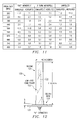
- FIG. 3 illustrated the unrolled planar material used to construct the antenna of FIGS. 1 and 2.
- FIGS. 4 and 5 illustrate two turn configurations of the antenna.
- FIGS. 6 and 7 illustrate three turn configurations of the antenna.
- FIG. 8 illustrates a four turn configuration of the antenna.
- FIG. 9 illustrates the results of radiation pattern simulations of the antenna.
- FIGS. 10A-10C illustrates measured VSWR data for fat monopole, unrolled, and three turn configurations of the antenna, respectively.
- FIG. 11 compares measured versus simulated VSWR data for each of the configurations of FIGS. 10A-10C.
- FIG. 12 illustrates the antenna with a radome and installed for use over a ground plane.
- FIG. 13 illustrates the VSWR performance of the antenna of FIG. 12 .
- FIGS. 14 and 15 illustrate the antenna used as elements of a dipole configuration.
- FIGS. 1 and 2 are a side view and a cross sectional view, respectively, of a wideband multi-mode antenna 10 in accordance with the invention.
- antenna 10 is a helical structure, formed from planar material. It exhibits a low VSWR over a wide frequency range. More specifically, antenna 10 has been demonstrated to provide less than 3:1 VSWR over an octave or more bandwidth. This low VSWR is easily matched to transmitters and receivers and associated devices.
- antenna 10 is constructed by rolling a right triangle shaped conductive material into a spiral having length Y and diameter D. Structurally, antenna 10 may be described as a tapered area small helix.
- An example of a suitable conductive material is 0.005 inch (0.127 mm) thick copper sheet.
- Variations of antenna 10 may be constructed with triangularly shaped material, where the hypotenuse is curved (concave or convex) rather than straight.
- Mesh or grid material, having fine mesh or grid spacing has been shown to have equal performance especially when weight or wind loading are factors.
- antenna 10 is electrically small. Its largest dimension (its height) is less than a wavelength at the lowest useful frequency (the frequency at which the VSWR rapidly improves). Dimension Y is typically about 0.2 to 0.24 ⁇ at the lowest useful frequency.
- antenna 10 is not a true circle and tapers from base to tip, its diameter, D, is taken at the base and is approximated by twice the radius from the center to the outermost point on the antenna.
- antenna 10 may be configured as a monopole and mounted above a conductive ground plane. However, antenna 10 may also be used as elements of other configurations, such as dipole antennas or antenna arrays.
- FIGS. 4-8 illustrate various monopole configurations of antenna 10 , including two, three, and four turn antennas.
- FIGS. 4-7 illustrates two and three turn antennas, 40 , 50 , 60 , 70 , with height to diameter ratios of 5:1 and 10:1, respectively.
- FIG. 8 illustrates a four turn antenna 80 , with a height to diameter ratio of 10:1.
- references to antenna 10 are meant to include the variations depicted in FIGS. 4-8, unless the context indicates otherwise.
- antenna 10 may also be compared to a “fat” monopole, or a flat planar surface equivalent to an unrolled monopole.
- These configurations represent examples of rolled and unrolled limiting configurations of antenna 10 .
- a fat monopole approximates antenna 10 as the spacing between turns decreases to zero and the number of turns increases for a given base dimension.
- a suitable method is to use approximations to the antenna current distribution. This may be accomplished by using finite element methods, which break the planar surface into a large number of mathematically definable segments that approximate the surface. There are a number of methods for generating and solving a large number of segments.
- MoM The method of moments
- GNEC-4 is a Microsoft Windows compatible version of the basic NEC (Navel Electric Code) software.
- AWAS Wire Antennas and Scatters
- antenna 10 and variations were modeled to determine the effect of various parameters on VSWR, pattern, radiation efficiency, and electrical size. These parameters include:
- Simulations were used to establish a set of design guidelines, which are set out below. These guidelines include both general observations about the effects produced by parameter variation, as well as specific observations for design of a monopole antenna with at least one octave of low VSWR ( ⁇ 3:1) performance at radio frequencies from a few megaHertz to several gigaHertz.
- antenna 10 As compared to a “fat” monopole or unrolled version, has a better current distribution across a wider range of frequencies.
- a feature of all configurations of antenna 10 is that it has both linear and spiral surfaces continuously connected from the base of the antenna to the tip.
- a cross section of antenna 10 at any point from the base to the tip produces a spiral. This spiral shortens in length for cross sections taken closer to the tip. At the tip, the spiral reduces in length to a point.
- this combination of linear and curvilinear surfaces produces multiple radiation modes which contribute both to low VSWR and differences in radiation polarization.
- an antenna 10 has been tested that produces linear polarization near the first resonance, transitioning to axial mode circular polarization at frequencies where the circumference is greater than about 0.7 wavelengths.
- antenna pattern simulations provide insight into the expected radiation pattern of antenna 10 .
- FIG. 9 illustrates the results of a simulation of polarization versus elevation angle for a three turn configuration of antenna 10 , such as the configuration of FIG. 7 .
- antenna 10 is omni-directional, akin to a typical monopole.
- antenna 10 is more circularly polarized, akin to a helical antenna.
- FIGS. 10A and 10B illustrate the VSWR performance of a 10:1 “fat” monopole and of an unrolled antenna, respectively. As stated above, these versions are represent two extremes of how the turns of antenna 10 may be configured.
- FIG. 10C illustrates the VSWR performance of a 10:1 three turn configuration of antenna 10 , such as the embodiment of FIG. 7 . For each figure, the frequency range is 200 to 2200 MHz.
- FIG. 11 illustrates the results of both computer simulated and experimental tests with real antenna configurations.
- Three configurations were tested: the fat monopole, a three turn antenna 70 , and an unrolled antenna.
- the VSWR was both simulated and measured over a design bandwidth of 200 to 800 MHz.
- FIG. 11 lists the VSWR data obtained by visually taking ten VSWR data points from each graph at equally spaced frequencies. From the data, the calculated correlation coefficient between simulated and measured data is 0.98 for antenna 70 , 0.96 for the fat monopole, and 0.83 for the unrolled antenna.
- the guidelines are applicable to various configurations of antenna 10 , such as the examples of FIGS. 4-8.
- the design objectives were to accommodate radio frequencies ranging from a few MHz to several GHz with low VSWR.
- antenna 10 should have a height to diameter ratio of 15:1 or less.
- a ratio of 1:1 should be considered a minimum; this ratio produces a structure similar to a spiral antenna above a ground plane.
- the impedance and pattern characteristics of antenna 10 with a height to diameter ratio greater than 20:1 approaches that of an equivalent ratio monopole.
- the real and imaginary impedance as a function of frequency vary to a lesser degree.
- the spacing between the base of the antenna and the groundplane is a critical parameter. This seems reasonable when it is considered that closer spacing increases capacitive reactance and reduces inductive reactance. Placing the antenna base closer to the groundplane reduces both the real and imaginary part of the input impedance. By varying the spacing, the VSWR can be optimized for various operating impedances. For a 50 Ohm antenna, total length to spacing ratio on the order of 50:1 appears to be near optimum for a 10:1 height to diameter monopole.
- the far field radiation pattern of the antenna While still primarily omni-directional in azimuth, begins to develop lobes in the elevation pattern as well as axial mode circularly polarized radiation.
- the far field pattern of a monopole is effectively identical to that of a conventional monopole.
- a lower height to diameter ratio provides less variation in the real impedance at frequencies above the first resonance. Therefore, a 5:1 ratio will provide less variation in VSWR over frequencies above the first resonance.
- the radiation mode of low ratio antennas may transition from linear to circular faster as frequency increases.
- the feed point For low VSWR at frequencies within the first octave above the first resonance (zero imaginary impedance) the feed point should be on the antenna base at the inner most point of the turns. For best overall average VSWR at all frequencies above the first resonance the feed point should be half way along the spiral base.
- the low frequency 2:1 VSWR cut off is nominally the frequency where the overall height (feed height plus element height) above the ground plane is 90% of a quarter wavelength at that frequency.
- Concave tapering of the surface decreases the average VSWR without significantly decreasing the VSWR bandwidth.
- the current distribution along an antenna element changes linear (along the length of the antenna) to circular (parallel to the ground plane) as the frequency is increased beyond an octave above the first resonance.
- Empirical tests indicate that dielectric material between the turns increases the capacitance between turns and is therefore somewhat equivalent to closer spacing of turns, and lower VSWR.
- Dielectric material may be used to control the spacing between turns, whether the spacing be uniform or varying.
- the number of turns is not critical.
- the height to base ratio of the planar surface establishes the number of turns for a given base diameter and turns spacing.
- the conductive material thickness should be less than 0.002 of the overall height H of the monopole so that it is effectively “thin” compared to the other antenna dimensions.
- the unrolled planar material used to form the antenna should be cut as a right triangle with the height of the vertical axis Y determined by the low frequency f of the ocatave bandwidth.
- S is the spacing between the ground plane and the bottom of the monopole
- K is a constant that can range from 1.3 to 1.7.
- the higher value for K will produce wider bandwidth, but higher average VSWR.
- the lower value will produce a narrower bandwidth, but lower average VSWR.
- the feed point for maximum low VSWR bandwidth (one octave above the first resonance) is the innermost point of the base spiral.
- the design guidelines set out above have been especially developed for a single octave antenna. However, with appropriate testing, wider bandwidths may be achieved. Notably, for certain values of K as the ratio of height to base decreases, the VSWR bandwidth widens to more than two octaves for VSWR less than about 3:1 with a 50 ohm reference.
- feed points With respect to feed points, different feed points along the spiral base change not only the VSWR bandwidth of the first resonance to second resonance of a monopole, but also the second resonance and higher resonance regions.
- VSWR control techniques such as shaping the hypotenuse of the planar surface, it may be possible to design a very broadband antenna or antenna with an useful frequency stop band (high VSWR region).
- Use of tunable feed points may yield a broadband antenna with a built-in tunable stop band filter. This could serve the interference mitigation purpose in the frequency domain that null-steering serves in the spatial domain.
- FIG. 12 illustrates an antenna 120 especially configured for the 225 to 400 MHz military communications band.
- the conductive material thickness used for antenna 120 is 0.005 inch (0.127 mm) thick copper sheet.
- Antenna 120 is mounted on a metal plate 126 , which provides a ground plane.
- a spacing S could be set at 0.0036 meters for an overall height H of the monopole above the ground plane of 0.293 meters.
- the number of turns is set by the H dimension and the value selected for K.
- the feed point for maximum low VSWR bandwidth (one octave above the first resonance) is the innermost point of the base spiral.
- the thin copper material selected for the antenna may be protected or supported by some form of mechanical support to produce a physically rugged antenna.
- the antenna element 122 is mounted within a low loss radome 125 , which stabilizes the turns spacing and provides a weather resistant shield. It may be made from a material, such as plastic tubing.
- the interior of the radome 125 is potted with a low loss dielectric foam filler 123 , which fills the spacing between the turns of the antenna element 122 .
- the dielectric filler 123 also serves to hold the spacing between turns.
- the size of the antenna should be small enough that thin material ( ⁇ 0.2 mm thick) should provide enough rigidity so that foam potting would not be necessay.
- antenna 120 is mounted on a delrin base 124 .
- the use of such a base which has a dielectric constant of 3.7, may add capacitance between the antenna element 122 and the ground plane 126 . This effect may be alleviated by using lower dielectric constant material for the radome attachment point and spacing it further from the antenna element 122 .
- FIG. 13 illustrates the VSWR performance of antenna 120 .
- antenna 120 provides a 3:1 VSWR bandwidth of more than 80% of the center frequency (see FIG. 61 ). Its volume is small compared to a conventional monopole—its base diameter is 10% of its height and it tapers to a point at its tip.
- Antenna 120 provides a superior VSWR bandwidth compared to any monopole within a volume equal or less than a TASH monopole.
- antenna 120 would not normally require a matching network. Essentially, it incorporates a matching network into the antenna configuration. The additional inductance and capacitance of the configuration is distributed in a manner that changes the current distribution on the antenna as a function of frequency. The change in current flow is complex and significantly different than current on a simple linear monopole of the same size. This change in distribution appears to provide additional VSWR bandwidth beyond what would be possible by simple impedance transformation matching networks applied to a conventional monopole.
- antenna 10 A fundamental difference between antenna 10 and conventional planar helical antennas is that the surface of antenna 10 has both a linear surface component along the antenna axis and a helical component around the antenna axis. This allows both linear and helical current to flow on the same structure.
- Planar and tapered surface helical antennas have only helical surfaces (no linear current flow), so current only follows a helical path.
- Antenna 10 does not act like a large number of monopoles connected in parallel. It does provide multiple sheet current paths for signals applied at one point at its base.
- One dominant path is the straight path produced by the quarter wave resonance due to the vertical edge of the inside turn.
- Another dominant path is the resonant path produced by the outside spiral edge of the helix.
- Antenna arrays using monopoles or dipoles (yagi, planar array, corner reflector, etc.) as their fundamental elements may benefit by replacing conventional dipole/monopole elements with elements having the configuration of antenna 10 .
- FIGS. 14 and 15 illustrate dipole antennas 140 and 150 , respetively, in accordance with the invention.
- Antenna 140 is equivalent to a monopole above a ground plane.
- Antenna 150 is a reverse image version. Simulations indicate that antenna 150 has the same VSWR properties as antenna 140 except for the impedance at the first low impedance resonance. The radiation resistance is higher because the reverse image current do not cancel as they do in the conventional image represented by antenna 140 .
- antenna 10 may be configured to form arrays.
- the resulting array provides a wider bandwidth than arrays comprised of conventional elements.
- VSWR may be easily referenced to a 50 ohm impedance system.
Abstract
A wideband multi-mode antenna having low VSWR operating characteristics. The antenna is has a shape similar to a helical antenna, but is formed from a right-triangularly shaped piece of conductive material. The result is a rolled planar antenna having a height and diameter predetermined to provide optimum VSWR for a given frequency range.
Description
This invention relates to antennas, and more particularly to an antenna based on a tapered helix configuration and having low VSWR over a wide bandwidth, and multi-mode operation.
Most antennas are capable of efficient operation over only a limited range of frequencies. For efficient energy radiation or reception, conventional antenna designs calls for antenna dimensions that are on the same order as the operating wavelength (λ). Efficient antenna operation requires not only efficient radiation or reception, the antenna must also be matched to the specific source or load for maximum energy transfer.
Antenna match quality is determined by the voltage standing wave ratio (VSWR) of the antenna at each frequency of interest. A perfect match requires a one-to-one ratio at all frequencies.
For broadband applications, there are several types of antennas that can be designed to provide a low VSWR over wide frequency ranges. Some of these antennas are inherently directional such as the conical spiral and log periodic. Others are omni-directional such as the bicone and tapered blade antennas.
Although there are a number of antenna configurations that can provide a low VSWR over a wide band, most have some limitations that make them unacceptable for many applications. For example, a log periodic antenna can easily be designed to provide low VSWR over several frequency octaves. But, the log periodic phase center, the effective radiating point of the antenna, varies with frequency and a log periodic is physically quite large compared to the wavelength of its lowest operating frequency. A bicone antenna or its monopole is capable of providing low VSWR over a wide bandwidth, but occupies a large volume compared to narrow band antennas having the same low end operating frequency. Generally, wideband antennas are difficult to design for low VSWR over more than an octave frequency range and are generally much larger than a wavelength at their lowest usable frequency.
Antennas, whether broadband or not, are not required to have low VSWR; many conventional antenna designs typically exhibit a high VSWR (>3:1). However, a high VSWR adversely affects efficiency, unless some form of compensatory matching network is used. But matching networks create new problems—most matching networks are not broadband and they tend to decrease the power available for transmission. For high power transmitters, matching networks must often be designed with electro-mechanical tuning elements. Such designs are costly and make automation of the matching function must slower than is possible with lower-power solid state tuning elements. In general, impedance matching to achieve a low VSWR is relatively easy for narrow band antennas (<10% of center frequency), but more difficult for wideband antennas (>20% of center frequency).
One aspect of the invention is a wideband multi-mode antenna. In its simplest form, the antenna is made from a single right triangularly shaped sheet of conductive material, having a height and a base dimension. The planar material is rolled, such that the antenna has the height of the planar material, a number of turns having spacing between them, a base diameter, and a pointed tip.
An advantage of the invention is that the antenna is compact, low cost, and easily manufactured. It provides a low VSWR that can be easily matched over a wide range of frequencies. With these features, the antenna has ready application to many existing systems as well as to new systems now under development for the wireless market. The potential for small size and wide bandwidth make the antenna especially useful for mobile communications and multi-mode radios.
FIGS. 1 and 2 are a side view and a cross sectional view, respectively, of a wideband multi-mode antenna in accordance with the invention.
FIG. 3 illustrated the unrolled planar material used to construct the antenna of FIGS. 1 and 2.
FIGS. 4 and 5 illustrate two turn configurations of the antenna.
FIGS. 6 and 7 illustrate three turn configurations of the antenna.
FIG. 8 illustrates a four turn configuration of the antenna.
FIG. 9 illustrates the results of radiation pattern simulations of the antenna.
FIGS. 10A-10C illustrates measured VSWR data for fat monopole, unrolled, and three turn configurations of the antenna, respectively.
FIG. 11 compares measured versus simulated VSWR data for each of the configurations of FIGS. 10A-10C.
FIG. 12 illustrates the antenna with a radome and installed for use over a ground plane.
FIG. 13 illustrates the VSWR performance of the antenna of FIG. 12.
FIGS. 14 and 15 illustrate the antenna used as elements of a dipole configuration.
Overview of Structure and Operating Characteristics
FIGS. 1 and 2 are a side view and a cross sectional view, respectively, of a wideband multi-mode antenna 10 in accordance with the invention. As explained below, antenna 10 is a helical structure, formed from planar material. It exhibits a low VSWR over a wide frequency range. More specifically, antenna 10 has been demonstrated to provide less than 3:1 VSWR over an octave or more bandwidth. This low VSWR is easily matched to transmitters and receivers and associated devices.
As illustrated in FIG. 3, antenna 10 is constructed by rolling a right triangle shaped conductive material into a spiral having length Y and diameter D. Structurally, antenna 10 may be described as a tapered area small helix. An example of a suitable conductive material is 0.005 inch (0.127 mm) thick copper sheet.
Variations of antenna 10 may be constructed with triangularly shaped material, where the hypotenuse is curved (concave or convex) rather than straight. Mesh or grid material, having fine mesh or grid spacing has been shown to have equal performance especially when weight or wind loading are factors.
As further explained below, antenna 10 is electrically small. Its largest dimension (its height) is less than a wavelength at the lowest useful frequency (the frequency at which the VSWR rapidly improves). Dimension Y is typically about 0.2 to 0.24 λ at the lowest useful frequency.
Dimension D is typically about 0.02 λ at that frequency. Although in cross section, antenna 10 is not a true circle and tapers from base to tip, its diameter, D, is taken at the base and is approximated by twice the radius from the center to the outermost point on the antenna.
In operation, antenna 10 may be configured as a monopole and mounted above a conductive ground plane. However, antenna 10 may also be used as elements of other configurations, such as dipole antennas or antenna arrays.
FIGS. 4-8 illustrate various monopole configurations of antenna 10, including two, three, and four turn antennas. FIGS. 4-7 illustrates two and three turn antennas, 40, 50, 60, 70, with height to diameter ratios of 5:1 and 10:1, respectively. FIG. 8 illustrates a four turn antenna 80, with a height to diameter ratio of 10:1. For purposes of this description, references to antenna 10 are meant to include the variations depicted in FIGS. 4-8, unless the context indicates otherwise.
For performance evaluation purposes, antenna 10 may also be compared to a “fat” monopole, or a flat planar surface equivalent to an unrolled monopole. These configurations represent examples of rolled and unrolled limiting configurations of antenna 10. For example, a fat monopole approximates antenna 10 as the spacing between turns decreases to zero and the number of turns increases for a given base dimension.
Antenna Modeling for VSWR Characteristics
For computer-aided modeling of antenna 10, a suitable method is to use approximations to the antenna current distribution. This may be accomplished by using finite element methods, which break the planar surface into a large number of mathematically definable segments that approximate the surface. There are a number of methods for generating and solving a large number of segments.
Among the more popular computer-aided modeling methods is the method of moments (MoM). One example of a specific modeling tools using the MoM is GNEC-4, which is a Microsoft Windows compatible version of the basic NEC (Navel Electric Code) software. Analysis of Wire Antennas and Scatters (AWAS) is another example of MoM antenna simulation software.
For purposes of this description, antenna 10 and variations, were modeled to determine the effect of various parameters on VSWR, pattern, radiation efficiency, and electrical size. These parameters include:
Number of helical turns
Helical turns spacing
Ratio of height to helical diameter
Taper of planar material (from feed point to end)
Feed height above a ground plane
Planar material thickness
Variation in helical diameter from the bottom to the top of the antenna element
Simulations were used to establish a set of design guidelines, which are set out below. These guidelines include both general observations about the effects produced by parameter variation, as well as specific observations for design of a monopole antenna with at least one octave of low VSWR (<3:1) performance at radio frequencies from a few megaHertz to several gigaHertz.
Current distribution simulations demonstrate how the current distribution for each configuration changes as a function of frequency. For example, antenna 10, as compared to a “fat” monopole or unrolled version, has a better current distribution across a wider range of frequencies.
Multi-Mode Characteristics
A feature of all configurations of antenna 10, such as those of FIGS. 4-7, is that it has both linear and spiral surfaces continuously connected from the base of the antenna to the tip. A cross section of antenna 10 at any point from the base to the tip produces a spiral. This spiral shortens in length for cross sections taken closer to the tip. At the tip, the spiral reduces in length to a point. As explained below, this combination of linear and curvilinear surfaces produces multiple radiation modes which contribute both to low VSWR and differences in radiation polarization. Specifically, as described below, an antenna 10 has been tested that produces linear polarization near the first resonance, transitioning to axial mode circular polarization at frequencies where the circumference is greater than about 0.7 wavelengths.
In addition to VSWR simulations, antenna pattern simulations provide insight into the expected radiation pattern of antenna 10.
FIG. 9 illustrates the results of a simulation of polarization versus elevation angle for a three turn configuration of antenna 10, such as the configuration of FIG. 7. As illustrated, at lower frequencies, antenna 10 is omni-directional, akin to a typical monopole. At higher frequencies, antenna 10 is more circularly polarized, akin to a helical antenna.
Simulated and Experimental VSWR Data
FIGS. 10A and 10B illustrate the VSWR performance of a 10:1 “fat” monopole and of an unrolled antenna, respectively. As stated above, these versions are represent two extremes of how the turns of antenna 10 may be configured. FIG. 10C illustrates the VSWR performance of a 10:1 three turn configuration of antenna 10, such as the embodiment of FIG. 7. For each figure, the frequency range is 200 to 2200 MHz.
FIG. 11 illustrates the results of both computer simulated and experimental tests with real antenna configurations. Three configurations were tested: the fat monopole, a three turn antenna 70, and an unrolled antenna. For each configuration, the VSWR was both simulated and measured over a design bandwidth of 200 to 800 MHz.
An attempt was made to establish a rough numerical correlation by simplifying the data. Thus, FIG. 11 lists the VSWR data obtained by visually taking ten VSWR data points from each graph at equally spaced frequencies. From the data, the calculated correlation coefficient between simulated and measured data is 0.98 for antenna 70, 0.96 for the fat monopole, and 0.83 for the unrolled antenna.
The fact that it is possible to build antennas with such good correlation to simulation implies that it is relatively insensitive to small variation in physical dimensions (<1%). This is remarkable, because for a typical conical spiral antenna, a change of only 0.01 λ in the separation of spiral arms makes an essential difference in the observed RF current distribution.
Although VSWR performance of antenna 10, in its various configurations, is insensitive to small irregularities, there appear to be three critical physical parameters. These are the height to base ratio, the feed point height above the ground plane, and the turns spacing. Of these three parameters, only feed height above the ground plane may be difficult to control in field situations. The other two parameters are primarily a function of the antenna's fabrication accuracy. Turns spacing, as well as the number of turns, are functions of the unrolled surface horizontal dimension. Referring again to FIG. 3, this is the dimension labeled Base=X.
Design Guidelines
The following are design guidelines for monopole antennas. The guidelines are applicable to various configurations of antenna 10, such as the examples of FIGS. 4-8. The design objectives were to accommodate radio frequencies ranging from a few MHz to several GHz with low VSWR.
Monopole antennas with height to diameter ratios greater than 15:1 showed a general decrease in VSWR bandwidth improvement compared to a conventional monopole of the same diameter. Thus, antenna 10 should have a height to diameter ratio of 15:1 or less. A ratio of 1:1 should be considered a minimum; this ratio produces a structure similar to a spiral antenna above a ground plane.
The impedance and pattern characteristics of antenna 10 with a height to diameter ratio greater than 20:1 approaches that of an equivalent ratio monopole.
As the monopole height to diameter ratio decreases, the real and imaginary impedance as a function of frequency vary to a lesser degree.
Trading off low 50 Ohm VSWR against linear polarization bandwidth, it appears that monopoles with height to diameter ratios between 5:1 and 15:1 provide the most bandwidth with linear polarization while maintaining a useful VSWR (<3:1) bandwidth.
The spacing between the base of the antenna and the groundplane is a critical parameter. This seems reasonable when it is considered that closer spacing increases capacitive reactance and reduces inductive reactance. Placing the antenna base closer to the groundplane reduces both the real and imaginary part of the input impedance. By varying the spacing, the VSWR can be optimized for various operating impedances. For a 50 Ohm antenna, total length to spacing ratio on the order of 50:1 appears to be near optimum for a 10:1 height to diameter monopole.
At frequencies beyond one octave above the first resonance, the far field radiation pattern of the antenna, while still primarily omni-directional in azimuth, begins to develop lobes in the elevation pattern as well as axial mode circularly polarized radiation.
From initial resonance to approximately one octave above the initial resonance, the far field pattern of a monopole is effectively identical to that of a conventional monopole.
A lower height to diameter ratio provides less variation in the real impedance at frequencies above the first resonance. Therefore, a 5:1 ratio will provide less variation in VSWR over frequencies above the first resonance. The radiation mode of low ratio antennas may transition from linear to circular faster as frequency increases.
For low VSWR at frequencies within the first octave above the first resonance (zero imaginary impedance) the feed point should be on the antenna base at the inner most point of the turns. For best overall average VSWR at all frequencies above the first resonance the feed point should be half way along the spiral base.
The low frequency 2:1 VSWR cut off is nominally the frequency where the overall height (feed height plus element height) above the ground plane is 90% of a quarter wavelength at that frequency.
Concave tapering of the surface decreases the average VSWR without significantly decreasing the VSWR bandwidth.
The current distribution along an antenna element changes linear (along the length of the antenna) to circular (parallel to the ground plane) as the frequency is increased beyond an octave above the first resonance.
As the spacing between turns is increased, the VSWR bandwidth increases. Maximum spacing appears to provide the widest bandwidth above the first resonance, at the expense of increased VSWR within that frequency range.
Empirical tests indicate that dielectric material between the turns increases the capacitance between turns and is therefore somewhat equivalent to closer spacing of turns, and lower VSWR. Dielectric material may be used to control the spacing between turns, whether the spacing be uniform or varying.
The number of turns is not critical. The height to base ratio of the planar surface establishes the number of turns for a given base diameter and turns spacing.
For a monopole antenna having minimum size, the following are design parameters for providing low VSWR over an octave bandwidth:
The conductive material thickness should be less than 0.002 of the overall height H of the monopole so that it is effectively “thin” compared to the other antenna dimensions.
The unrolled planar material used to form the antenna should be cut as a right triangle with the height of the vertical axis Y determined by the low frequency f of the ocatave bandwidth. The vertical axis length Y should be determined by Y=0.86(c/4f).
Where S is the spacing between the ground plane and the bottom of the monopole, typical ground plane to antenna spacing S should range between S=Y/80 to Y/30. Larger spacing increases both the real and imaginary impedance lower spacing reduces them. A good compromise value for S in a 50 Ohm system would be: S=Y/50. Overall height of the monopole above the groundplane is H where: H=Y+S.
The length of the horizontal axis X should be determined by X=Y/K, where K is a constant that can range from 1.3 to 1.7. The higher value for K will produce wider bandwidth, but higher average VSWR. The lower value will produce a narrower bandwidth, but lower average VSWR. A value of K=1.6 will produce a 2.5:1 VSWR octave bandwidth monopole.
Keeping the material spacing equal, turn the material to produce an antenna with maximum spiral diameter dimension D=of H/10. The number of total turns will be set by H and the value selected for K.
Reducing the spacing between turns narrows the VSWR bandwidth with minimal improvement in average VSWR. Maximum spacing between turns provides the widest VSWR bandwidth.
The feed point for maximum low VSWR bandwidth (one octave above the first resonance) is the innermost point of the base spiral.
The design guidelines set out above have been especially developed for a single octave antenna. However, with appropriate testing, wider bandwidths may be achieved. Notably, for certain values of K as the ratio of height to base decreases, the VSWR bandwidth widens to more than two octaves for VSWR less than about 3:1 with a 50 ohm reference.
With respect to feed points, different feed points along the spiral base change not only the VSWR bandwidth of the first resonance to second resonance of a monopole, but also the second resonance and higher resonance regions. With VSWR control techniques, such as shaping the hypotenuse of the planar surface, it may be possible to design a very broadband antenna or antenna with an useful frequency stop band (high VSWR region). Use of tunable feed points may yield a broadband antenna with a built-in tunable stop band filter. This could serve the interference mitigation purpose in the frequency domain that null-steering serves in the spatial domain.
Specific Design Parameters for 225 to 400 MHz Antenna
FIG. 12 illustrates an antenna 120 especially configured for the 225 to 400 MHz military communications band. The conductive material thickness used for antenna 120 is 0.005 inch (0.127 mm) thick copper sheet.
Unrolled planar material used to form the antenna was cut as a right triangle with the height of the vertical axis Y determined by the low frequency f of the desired bandwidth. Specifically, the vertical axis length Y is determined by Y=0.86(c/4f). For an f of 225 MHz the value for Y was 0.287 meters.
The base dimension X of the right triangle is determined by X=Y/K, where K can range from 1.3 to 1.7. Although less than a 3:1 VSWR octave bandwidth was desired, a value of K=1.6 was selected for mechnical design reasons.
The conductive material spacing was held equal as the material was rolled to produce an antenna with maximum (at the base) spiral diameter dimension of D=of H/10. In other words, the height to diameter ratio is 10:1. The number of turns is set by the H dimension and the value selected for K.
The feed point for maximum low VSWR bandwidth (one octave above the first resonance) is the innermost point of the base spiral.
The thin copper material selected for the antenna may be protected or supported by some form of mechanical support to produce a physically rugged antenna. In the example of FIG. 12, the antenna element 122 is mounted within a low loss radome 125, which stabilizes the turns spacing and provides a weather resistant shield. It may be made from a material, such as plastic tubing. The interior of the radome 125 is potted with a low loss dielectric foam filler 123, which fills the spacing between the turns of the antenna element 122. In the example of FIG. 12, the dielectric filler 123 also serves to hold the spacing between turns.
For a lower frequency range, a different construction technque could be more appropriate. For lower frequencies requiring larger antenna elements it would be possible to form the antenna surface from metal mesh supported by a rigid rod along the inside edge. Antennas of this type should be suitable for fixed locations. Wind loading could also be minimized by use of metal mesh.
For higher frequencies, the size of the antenna should be small enough that thin material (<0.2 mm thick) should provide enough rigidity so that foam potting would not be necessay.
As indicated in FIG. 12, antenna 120 is mounted on a delrin base 124. The use of such a base, which has a dielectric constant of 3.7, may add capacitance between the antenna element 122 and the ground plane 126. This effect may be alleviated by using lower dielectric constant material for the radome attachment point and spacing it further from the antenna element 122.
FIG. 13 illustrates the VSWR performance of antenna 120. As illustrated, antenna 120 provides a 3:1 VSWR bandwidth of more than 80% of the center frequency (see FIG. 61). Its volume is small compared to a conventional monopole—its base diameter is 10% of its height and it tapers to a point at its tip. Antenna 120 provides a superior VSWR bandwidth compared to any monopole within a volume equal or less than a TASH monopole.
Moreover, antenna 120 would not normally require a matching network. Essentially, it incorporates a matching network into the antenna configuration. The additional inductance and capacitance of the configuration is distributed in a manner that changes the current distribution on the antenna as a function of frequency. The change in current flow is complex and significantly different than current on a simple linear monopole of the same size. This change in distribution appears to provide additional VSWR bandwidth beyond what would be possible by simple impedance transformation matching networks applied to a conventional monopole.
In general, the above observations are true of the various configurations of antenna 10.
Impedance Characteristics
A fundamental difference between antenna 10 and conventional planar helical antennas is that the surface of antenna 10 has both a linear surface component along the antenna axis and a helical component around the antenna axis. This allows both linear and helical current to flow on the same structure. Planar and tapered surface helical antennas have only helical surfaces (no linear current flow), so current only follows a helical path.
In simulations, there are similarities between the impedance of the “fat” monopole and unrolled versions of antenna 10 in monopole form. Specifically, except for much lower values of real and imaginary impedance both have the same form although the imaginary impedance of the unrolled version is more inductive (positive reactance). In contrast, for antenna 10 the real and imaginary impedance curves have an additional resonance. This additional resonance is apparently responsible for the partial cancellation of the normal monopole capacitive reactance while decreasing the value of the real impedance thus producing a wide VSWR bandwidth.
More Complex Configurations
Antenna arrays using monopoles or dipoles (yagi, planar array, corner reflector, etc.) as their fundamental elements may benefit by replacing conventional dipole/monopole elements with elements having the configuration of antenna 10.
FIGS. 14 and 15 illustrate dipole antennas 140 and 150, respetively, in accordance with the invention. Antenna 140 is equivalent to a monopole above a ground plane. Antenna 150 is a reverse image version. Simulations indicate that antenna 150 has the same VSWR properties as antenna 140 except for the impedance at the first low impedance resonance. The radiation resistance is higher because the reverse image current do not cancel as they do in the conventional image represented by antenna 140.
As a fundamental antenna element, such as a loop or dipole, antenna 10 may be configured to form arrays. The resulting array provides a wider bandwidth than arrays comprised of conventional elements. When so mounted, VSWR may be easily referenced to a 50 ohm impedance system.
Other Embodiments
Although the present invention has been described in detail, it should be understood that various changes, substitutions, and alterations can be made hereto without departing from the spirit and scope of the invention as defined by the appended claims.
Claims (33)
1. A wideband multi-mode antenna, comprising:
an antenna element made from a single right triangularly shaped sheet of conductive material, the material having a height and a base dimension;
wherein the conductive material has a rolled shape, such that the antenna has the height of the conductive material, a number of turns having spacing between them, a base diameter, and a pointed tip.
2. The antenna of claim 1 , wherein the spacing between the turns is uniform.
3. The antenna of claim 1 , further comprising a dielectric material between the turns.
4. The antenna of claim 1 , wherein the ratio of the height to the diameter is less than 15:1.
5. The antenna of claim 1 , wherein the ratio of the height to the diameter is greater than 5:1.
6. The antenna of claim 1 , wherein the number of turns is less than four.
7. The antenna of claim 1 , wherein the conductive material is a mesh material.
8. The antenna of claim 1 , wherein the conductive material has a curved hypotenuse.
9. The antenna of claim 1 , further comprising a radome enclosing the antenna element.
10. The antenna of claim 1 , wherein the height is approximately in the range of 0.2 to 0.24 of the wavelength of a low frequency of operation.
11. The antenna of claim 1 , wherein the diameter is approximately 0.02 of the wavelength of a low frequency of operation.
12. The antenna of claim 1 , further comprising a ground plane upon which the antenna element is mounted.
13. The antenna of claim 12 , wherein the spacing between the ground plane and the base of the antenna element results in a ratio of approximately 50:1, representing the ratio of total height of the antenna above the ground plane to the spacing.
14. The antenna of claim 1 , wherein the height is approximately 0.86 times c divided by 4f, where f is a desired low frequency of operation.
15. The antenna of claim 1 , wherein the base is approximately the height divided by K, where K is a constant ranging from 1.3 to 1.7.
16. The antenna of claim 1 , wherein the thickness of the conductive material is less than 0.002 of the height.
17. The antenna of claim 1 , further comprising a feed point at the innermost point of the base.
18. A dipole type antenna, comprising:
two antenna elements, each made from a single right triangularly shaped sheet of conductive material, having a height and a base dimension;
wherein the conductive material has a rolled shape, such that the antenna has the height of the conductive material, a number of turns having spacing between them, a base diameter, and a pointed tip;
wherein the antenna elements are connected to form a dipole.
19. The antenna of claim 18 , wherein the antenna elements form mirror images.
20. The antenna of claim 18 , wherein the antenna elements form reverse images.
21. A method of manufacturing an antenna, comprising the steps of:
forming a right-triangularly shaped sheet of conductive material, having a height and a base dimension; and
rolling the material along the height dimension, to form the antenna such that the antenna has the height of the conductive material, a number of turns having spacing between them, a base diameter, and a pointed tip.
22. The method of claim 21 , wherein the rolling step is performed such that the spacing between turns is uniform.
23. The method of claim 21 , wherein the rolling step is performed such that the ratio of the height to the diameter is less than 15:1.
24. The method of claim 21 , wherein the rolling step is performed such that the ratio of the height to the diameter is greater than 5:1.
25. The method of claim 21 , wherein the height is approximately 0.86 times c divided by 4f, where f is a desired low frequency of operation.
26. The method of claim 21 , wherein the base is approximately the height divided by K, where K is a constant ranging from 1.3 to 1.7.
27. The method of claim 21 , wherein the thickness of the conductive material is less than 0.002 of the height.
28. The method of claim 21 , wherein the forming step and the rolling step are performed to provide a height to diameter ratio that results in a desired VSWR.
29. The method of claim 21 , further comprising the step of affixing an antenna feed point to the base of the antenna.
30. The method of claim 29 , wherein the feed point is at the innermost point of the base.
31. The method of claim 29 , wherein the feed point is placed at a location that produces a desired VSWR.
32. The method of claim 21 , further comprising the step of adjusting the spacing between turns to provide a desired bandwidth.
33. The method of claim 21 , further comprising the step of placing a dielectric material between the turns.
Priority Applications (4)
| Application Number | Priority Date | Filing Date | Title |
|---|---|---|---|
| US09/768,433 US6339409B1 (en) | 2001-01-24 | 2001-01-24 | Wide bandwidth multi-mode antenna |
| AU2002249918A AU2002249918A1 (en) | 2001-01-24 | 2002-01-07 | Wide bandwidth multi-mode antenna |
| PCT/US2002/000348 WO2002060010A2 (en) | 2001-01-24 | 2002-01-07 | Wide bandwidth multi-mode antenna |
| US10/758,564 USRE40129E1 (en) | 2001-01-24 | 2004-01-15 | Wide bandwidth multi-mode antenna |
Applications Claiming Priority (1)
| Application Number | Priority Date | Filing Date | Title |
|---|---|---|---|
| US09/768,433 US6339409B1 (en) | 2001-01-24 | 2001-01-24 | Wide bandwidth multi-mode antenna |
Related Child Applications (1)
| Application Number | Title | Priority Date | Filing Date |
|---|---|---|---|
| US10/758,564 Reissue USRE40129E1 (en) | 2001-01-24 | 2004-01-15 | Wide bandwidth multi-mode antenna |
Publications (1)
| Publication Number | Publication Date |
|---|---|
| US6339409B1 true US6339409B1 (en) | 2002-01-15 |
Family
ID=25082490
Family Applications (2)
| Application Number | Title | Priority Date | Filing Date |
|---|---|---|---|
| US09/768,433 Ceased US6339409B1 (en) | 2001-01-24 | 2001-01-24 | Wide bandwidth multi-mode antenna |
| US10/758,564 Expired - Lifetime USRE40129E1 (en) | 2001-01-24 | 2004-01-15 | Wide bandwidth multi-mode antenna |
Family Applications After (1)
| Application Number | Title | Priority Date | Filing Date |
|---|---|---|---|
| US10/758,564 Expired - Lifetime USRE40129E1 (en) | 2001-01-24 | 2004-01-15 | Wide bandwidth multi-mode antenna |
Country Status (3)
| Country | Link |
|---|---|
| US (2) | US6339409B1 (en) |
| AU (1) | AU2002249918A1 (en) |
| WO (1) | WO2002060010A2 (en) |
Cited By (30)
| Publication number | Priority date | Publication date | Assignee | Title |
|---|---|---|---|---|
| US20030201942A1 (en) * | 2002-04-25 | 2003-10-30 | Ethertronics, Inc. | Low-profile, multi-frequency, multi-band, capacitively loaded magnetic dipole antenna |
| US20030222826A1 (en) * | 2002-05-31 | 2003-12-04 | Ethertronics, Inc. | Multi-band, low-profile, capacitively loaded antennas with integrated filters |
| US6677915B1 (en) | 2001-02-12 | 2004-01-13 | Ethertronics, Inc. | Shielded spiral sheet antenna structure and method |
| US20040095281A1 (en) * | 2002-11-18 | 2004-05-20 | Gregory Poilasne | Multi-band reconfigurable capacitively loaded magnetic dipole |
| US20040125026A1 (en) * | 2002-12-17 | 2004-07-01 | Ethertronics, Inc. | Antennas with reduced space and improved performance |
| US20040145523A1 (en) * | 2003-01-27 | 2004-07-29 | Jeff Shamblin | Differential mode capacitively loaded magnetic dipole antenna |
| US20040257298A1 (en) * | 2003-06-18 | 2004-12-23 | Steve Larouche | Helical antenna |
| US6859175B2 (en) | 2002-12-03 | 2005-02-22 | Ethertronics, Inc. | Multiple frequency antennas with reduced space and relative assembly |
| US20050140561A1 (en) * | 2003-01-24 | 2005-06-30 | Marsan Lynn A. | Compact low RCS ultra-wide bandwidth conical monopole antenna |
| US20050243009A1 (en) * | 2004-04-29 | 2005-11-03 | Industrial Technology Research Institute | Omnidirectional broadband monopole antenna |
| US20050275594A1 (en) * | 2004-05-24 | 2005-12-15 | Amphenol-T&M Antennas | Multiple band antenna and antenna assembly |
| US7012568B2 (en) * | 2001-06-26 | 2006-03-14 | Ethertronics, Inc. | Multi frequency magnetic dipole antenna structures and methods of reusing the volume of an antenna |
| US20060071871A1 (en) * | 2004-10-05 | 2006-04-06 | Industrial Technology Research Institute | Omnidirectional ultra-wideband monopole antenna |
| US20060071873A1 (en) * | 2004-10-01 | 2006-04-06 | Warnagiris Thomas J | Improved tapered area small helix antenna |
| US20060176233A1 (en) * | 2005-02-04 | 2006-08-10 | Chia-Lun Tang | Planar monopole antenna |
| US7123209B1 (en) | 2003-02-26 | 2006-10-17 | Ethertronics, Inc. | Low-profile, multi-frequency, differential antenna structures |
| WO2006136980A2 (en) * | 2005-06-21 | 2006-12-28 | Koninklijke Philips Electronics N.V. | Antenna for suppressing spurious resonances |
| US20070210972A1 (en) * | 2006-03-09 | 2007-09-13 | Sensor Systems, Inc. | Wideband antenna systems and methods |
| US20070241982A1 (en) * | 2004-09-30 | 2007-10-18 | Alan Stigliani | Contoured triangular dipole antenna |
| US20080068281A1 (en) * | 2006-09-20 | 2008-03-20 | Radiall | Broadband antenna |
| US20080136729A1 (en) * | 2006-12-08 | 2008-06-12 | Electronics And Telecommunications Research Institute | Antenna matching device and transceiver having the same |
| US7460080B1 (en) * | 2005-11-04 | 2008-12-02 | Watson Iii Thomas B | Reducing drag caused by wind loads on communication tower appurtenances |
| US20100127952A1 (en) * | 2008-11-25 | 2010-05-27 | Motorola, Inc. | Dual helix, dual pitch antenna for wide frequency bandwidth |
| WO2010095175A1 (en) * | 2009-02-19 | 2010-08-26 | 新興産業株式會社 | Antenna |
| US20110148687A1 (en) * | 2009-12-18 | 2011-06-23 | L-3 Communications Cyterra Corporation | Adjustable antenna |
| US9407001B2 (en) | 2012-07-18 | 2016-08-02 | Jack Nilsson | Antenna assembly |
| US20180277959A1 (en) * | 2017-03-27 | 2018-09-27 | Trans Electric Co., Ltd. | Flat antenna |
| USD863268S1 (en) | 2018-05-04 | 2019-10-15 | Scott R. Archer | Yagi-uda antenna with triangle loop |
| US11177563B2 (en) | 2019-08-15 | 2021-11-16 | United States Of America As Represented By The Secretary Of The Navy | Lower element ground plane apparatus and methods for an antenna system |
| CN115275584A (en) * | 2022-09-26 | 2022-11-01 | 华南理工大学 | Broadband bidirectional radiation same-rotation-direction circularly polarized helical antenna based on 3D printing technology |
Families Citing this family (2)
| Publication number | Priority date | Publication date | Assignee | Title |
|---|---|---|---|---|
| US8884838B2 (en) | 2012-05-15 | 2014-11-11 | Motorola Solutions, Inc. | Multi-band subscriber antenna for portable two-way radios |
| US9887462B2 (en) | 2013-10-31 | 2018-02-06 | Motorola Solutions, Inc. | Antenna with embedded wideband matching substrate |
Citations (10)
| Publication number | Priority date | Publication date | Assignee | Title |
|---|---|---|---|---|
| US4169267A (en) | 1978-06-19 | 1979-09-25 | The United States Of America As Represented By The Secretary Of The Air Force | Broadband helical antennas |
| US4649396A (en) | 1985-08-26 | 1987-03-10 | Hazeltine Corporation | Double-tuned blade monopole |
| US4697192A (en) | 1985-04-16 | 1987-09-29 | Texas Instruments Incorporated | Two arm planar/conical/helix antenna |
| US5216436A (en) | 1991-05-31 | 1993-06-01 | Harris Corporation | Collapsible, low visibility, broadband tapered helix monopole antenna |
| US5349365A (en) | 1991-10-21 | 1994-09-20 | Ow Steven G | Quadrifilar helix antenna |
| US5479182A (en) | 1993-03-01 | 1995-12-26 | Her Majesty The Queen In Right Of Canada, As Represented By The Minister Of Communications | Short conical antenna |
| US5668559A (en) | 1993-10-14 | 1997-09-16 | Alcatel Mobile Communication France | Antenna for portable radio devices |
| US5892480A (en) | 1997-04-09 | 1999-04-06 | Harris Corporation | Variable pitch angle, axial mode helical antenna |
| US6150984A (en) * | 1996-12-04 | 2000-11-21 | Kyocera Corporation | Shared antenna and portable radio device using the same |
| US6278414B1 (en) * | 1996-07-31 | 2001-08-21 | Qualcomm Inc. | Bent-segment helical antenna |
Family Cites Families (5)
| Publication number | Priority date | Publication date | Assignee | Title |
|---|---|---|---|---|
| GB322614A (en) * | 1928-11-08 | 1929-12-12 | Walter Richard Everett | Improvements in radio or wireless aerials (antenna) for emission or reception |
| GB712265A (en) * | 1952-02-14 | 1954-07-21 | Nat Res Dev | Improvements in or relating to aerials |
| US3868694A (en) * | 1973-08-09 | 1975-02-25 | Us Air Force | Dielectric directional antenna |
| US4148030A (en) * | 1977-06-13 | 1979-04-03 | Rca Corporation | Helical antennas |
| US7126557B2 (en) * | 2004-10-01 | 2006-10-24 | Southwest Research Institute | Tapered area small helix antenna |
-
2001
- 2001-01-24 US US09/768,433 patent/US6339409B1/en not_active Ceased
-
2002
- 2002-01-07 AU AU2002249918A patent/AU2002249918A1/en not_active Abandoned
- 2002-01-07 WO PCT/US2002/000348 patent/WO2002060010A2/en not_active Application Discontinuation
-
2004
- 2004-01-15 US US10/758,564 patent/USRE40129E1/en not_active Expired - Lifetime
Patent Citations (10)
| Publication number | Priority date | Publication date | Assignee | Title |
|---|---|---|---|---|
| US4169267A (en) | 1978-06-19 | 1979-09-25 | The United States Of America As Represented By The Secretary Of The Air Force | Broadband helical antennas |
| US4697192A (en) | 1985-04-16 | 1987-09-29 | Texas Instruments Incorporated | Two arm planar/conical/helix antenna |
| US4649396A (en) | 1985-08-26 | 1987-03-10 | Hazeltine Corporation | Double-tuned blade monopole |
| US5216436A (en) | 1991-05-31 | 1993-06-01 | Harris Corporation | Collapsible, low visibility, broadband tapered helix monopole antenna |
| US5349365A (en) | 1991-10-21 | 1994-09-20 | Ow Steven G | Quadrifilar helix antenna |
| US5479182A (en) | 1993-03-01 | 1995-12-26 | Her Majesty The Queen In Right Of Canada, As Represented By The Minister Of Communications | Short conical antenna |
| US5668559A (en) | 1993-10-14 | 1997-09-16 | Alcatel Mobile Communication France | Antenna for portable radio devices |
| US6278414B1 (en) * | 1996-07-31 | 2001-08-21 | Qualcomm Inc. | Bent-segment helical antenna |
| US6150984A (en) * | 1996-12-04 | 2000-11-21 | Kyocera Corporation | Shared antenna and portable radio device using the same |
| US5892480A (en) | 1997-04-09 | 1999-04-06 | Harris Corporation | Variable pitch angle, axial mode helical antenna |
Cited By (48)
| Publication number | Priority date | Publication date | Assignee | Title |
|---|---|---|---|---|
| US6677915B1 (en) | 2001-02-12 | 2004-01-13 | Ethertronics, Inc. | Shielded spiral sheet antenna structure and method |
| US7012568B2 (en) * | 2001-06-26 | 2006-03-14 | Ethertronics, Inc. | Multi frequency magnetic dipole antenna structures and methods of reusing the volume of an antenna |
| US20030201942A1 (en) * | 2002-04-25 | 2003-10-30 | Ethertronics, Inc. | Low-profile, multi-frequency, multi-band, capacitively loaded magnetic dipole antenna |
| US6943730B2 (en) | 2002-04-25 | 2005-09-13 | Ethertronics Inc. | Low-profile, multi-frequency, multi-band, capacitively loaded magnetic dipole antenna |
| US20030222826A1 (en) * | 2002-05-31 | 2003-12-04 | Ethertronics, Inc. | Multi-band, low-profile, capacitively loaded antennas with integrated filters |
| US6911940B2 (en) * | 2002-11-18 | 2005-06-28 | Ethertronics, Inc. | Multi-band reconfigurable capacitively loaded magnetic dipole |
| US20040095281A1 (en) * | 2002-11-18 | 2004-05-20 | Gregory Poilasne | Multi-band reconfigurable capacitively loaded magnetic dipole |
| US6859175B2 (en) | 2002-12-03 | 2005-02-22 | Ethertronics, Inc. | Multiple frequency antennas with reduced space and relative assembly |
| US20040125026A1 (en) * | 2002-12-17 | 2004-07-01 | Ethertronics, Inc. | Antennas with reduced space and improved performance |
| US7084813B2 (en) | 2002-12-17 | 2006-08-01 | Ethertronics, Inc. | Antennas with reduced space and improved performance |
| US7116278B2 (en) * | 2003-01-24 | 2006-10-03 | Bae Systems Information And Electronic Systems Integration Inc. | Compact low RCS ultra-wide bandwidth conical monopole antenna |
| US20050140561A1 (en) * | 2003-01-24 | 2005-06-30 | Marsan Lynn A. | Compact low RCS ultra-wide bandwidth conical monopole antenna |
| US6919857B2 (en) | 2003-01-27 | 2005-07-19 | Ethertronics, Inc. | Differential mode capacitively loaded magnetic dipole antenna |
| US20040145523A1 (en) * | 2003-01-27 | 2004-07-29 | Jeff Shamblin | Differential mode capacitively loaded magnetic dipole antenna |
| US7123209B1 (en) | 2003-02-26 | 2006-10-17 | Ethertronics, Inc. | Low-profile, multi-frequency, differential antenna structures |
| US20040257298A1 (en) * | 2003-06-18 | 2004-12-23 | Steve Larouche | Helical antenna |
| US7038636B2 (en) | 2003-06-18 | 2006-05-02 | Ems Technologies Cawada, Ltd. | Helical antenna |
| US20050243009A1 (en) * | 2004-04-29 | 2005-11-03 | Industrial Technology Research Institute | Omnidirectional broadband monopole antenna |
| US7327327B2 (en) | 2004-04-29 | 2008-02-05 | Industrial Technology Research Institute | Omnidirectional broadband monopole antenna |
| US20050275594A1 (en) * | 2004-05-24 | 2005-12-15 | Amphenol-T&M Antennas | Multiple band antenna and antenna assembly |
| US7161538B2 (en) * | 2004-05-24 | 2007-01-09 | Amphenol-T&M Antennas | Multiple band antenna and antenna assembly |
| US20070241982A1 (en) * | 2004-09-30 | 2007-10-18 | Alan Stigliani | Contoured triangular dipole antenna |
| US20060071873A1 (en) * | 2004-10-01 | 2006-04-06 | Warnagiris Thomas J | Improved tapered area small helix antenna |
| US7126557B2 (en) * | 2004-10-01 | 2006-10-24 | Southwest Research Institute | Tapered area small helix antenna |
| US20060071871A1 (en) * | 2004-10-05 | 2006-04-06 | Industrial Technology Research Institute | Omnidirectional ultra-wideband monopole antenna |
| US7495616B2 (en) | 2004-10-05 | 2009-02-24 | Industrial Technology Research Institute | Omnidirectional ultra-wideband monopole antenna |
| US20060176233A1 (en) * | 2005-02-04 | 2006-08-10 | Chia-Lun Tang | Planar monopole antenna |
| US7126543B2 (en) | 2005-02-04 | 2006-10-24 | Industrial Technology Research Institute | Planar monopole antenna |
| WO2006136980A2 (en) * | 2005-06-21 | 2006-12-28 | Koninklijke Philips Electronics N.V. | Antenna for suppressing spurious resonances |
| WO2006136980A3 (en) * | 2005-06-21 | 2007-03-08 | Koninkl Philips Electronics Nv | Antenna for suppressing spurious resonances |
| US7460080B1 (en) * | 2005-11-04 | 2008-12-02 | Watson Iii Thomas B | Reducing drag caused by wind loads on communication tower appurtenances |
| US7633451B2 (en) | 2006-03-09 | 2009-12-15 | Sensor Systems, Inc. | Wideband antenna systems and methods |
| US20070210972A1 (en) * | 2006-03-09 | 2007-09-13 | Sensor Systems, Inc. | Wideband antenna systems and methods |
| AU2007216789B2 (en) * | 2006-09-20 | 2010-11-18 | Radiall | A broadband antenna |
| US20080068281A1 (en) * | 2006-09-20 | 2008-03-20 | Radiall | Broadband antenna |
| FR2906085A1 (en) * | 2006-09-20 | 2008-03-21 | Radiall Sa | WIDE BAND ADAPTATION ANTENNA |
| EP1903636A1 (en) * | 2006-09-20 | 2008-03-26 | Radiall | Antenna with wide adaptation band |
| US20080136729A1 (en) * | 2006-12-08 | 2008-06-12 | Electronics And Telecommunications Research Institute | Antenna matching device and transceiver having the same |
| US7840200B2 (en) * | 2006-12-08 | 2010-11-23 | Electronics And Telecommunications Research Institute | Antenna matching device and transceiver having the same |
| US20100127952A1 (en) * | 2008-11-25 | 2010-05-27 | Motorola, Inc. | Dual helix, dual pitch antenna for wide frequency bandwidth |
| WO2010095175A1 (en) * | 2009-02-19 | 2010-08-26 | 新興産業株式會社 | Antenna |
| US20110148687A1 (en) * | 2009-12-18 | 2011-06-23 | L-3 Communications Cyterra Corporation | Adjustable antenna |
| US9407001B2 (en) | 2012-07-18 | 2016-08-02 | Jack Nilsson | Antenna assembly |
| US20180277959A1 (en) * | 2017-03-27 | 2018-09-27 | Trans Electric Co., Ltd. | Flat antenna |
| US10164341B2 (en) * | 2017-03-27 | 2018-12-25 | Trans Electric Co., Ltd. | Flat antenna |
| USD863268S1 (en) | 2018-05-04 | 2019-10-15 | Scott R. Archer | Yagi-uda antenna with triangle loop |
| US11177563B2 (en) | 2019-08-15 | 2021-11-16 | United States Of America As Represented By The Secretary Of The Navy | Lower element ground plane apparatus and methods for an antenna system |
| CN115275584A (en) * | 2022-09-26 | 2022-11-01 | 华南理工大学 | Broadband bidirectional radiation same-rotation-direction circularly polarized helical antenna based on 3D printing technology |
Also Published As
| Publication number | Publication date |
|---|---|
| AU2002249918A1 (en) | 2002-08-06 |
| USRE40129E1 (en) | 2008-03-04 |
| WO2002060010A2 (en) | 2002-08-01 |
| WO2002060010A8 (en) | 2004-07-08 |
| WO2002060010A3 (en) | 2003-02-20 |
Similar Documents
| Publication | Publication Date | Title |
|---|---|---|
| US6339409B1 (en) | Wide bandwidth multi-mode antenna | |
| EP2692016B1 (en) | Wireless communications device including side-by-side passive loop antennas and related methods | |
| US7126557B2 (en) | Tapered area small helix antenna | |
| Ray | Design aspects of printed monopole antennas for ultra-wide band applications | |
| Emadian et al. | Very small dual band-notched rectangular slot antenna with enhanced impedance bandwidth | |
| Zhu et al. | A compact transmission-line metamaterial antenna with extended bandwidth | |
| KR101155715B1 (en) | Folded conical antenna and associated methods | |
| US9431712B2 (en) | Electrically-small, low-profile, ultra-wideband antenna | |
| Moon et al. | An extremely low-profile ferrite-loaded wideband VHF antenna design | |
| US20060250319A1 (en) | Antenna apparatus and method of forming same | |
| Akhoondzadeh-Asl et al. | Novel low profile wideband monopole antenna for avionics applications | |
| Jung et al. | Electromagnetically coupled small broadband monopole antenna | |
| Tirado-Mendez et al. | Inductively-loaded Yagi-Uda antenna with cylindrical cover for size reduction at VHF-UHF bands | |
| Liu et al. | A compact-size and high-efficiency cage antenna for 2.4-GHz WLAN access points | |
| CN102460830A (en) | An electrically small ultra-wideband antenna for mobile handsets and computer networks | |
| Bernard et al. | Microstrip antenna design using transmission line model | |
| Elsheakh et al. | Ultra-wide-bandwidth (UWB) microstrip monopole antenna using split ring resonator (SRR) structure | |
| Kim et al. | Tapered type PIFA design for mobile phones at 1800 MHz | |
| Sivasundarapandian et al. | A planar multiband Koch snowflake fractal antenna for cognitive radio | |
| US9343810B2 (en) | Method of making an extremely low profile wideband antenna | |
| Mazloum et al. | Utilization of Protruded Strip Resonators to Design a Compact UWB Antenna with WiMAX and WLAN Notch Bands. | |
| WO2003094293A1 (en) | Slot antenna | |
| Lin et al. | Parametric study of dual-band operation in a microstrip-fed uniplanar monopole antenna | |
| US7450081B1 (en) | Compact low frequency radio antenna | |
| Wang et al. | A frequency-reduction scheme for spiral slot antenna |
Legal Events
| Date | Code | Title | Description |
|---|---|---|---|
| AS | Assignment |
Owner name: SOUTHWEST RESEARCH INSTITUTE, TEXAS Free format text: ASSIGNMENT OF ASSIGNORS INTEREST;ASSIGNOR:WARNAGIRIS, THOMAS J.;REEL/FRAME:011865/0621 Effective date: 20010406 |
|
| STCF | Information on status: patent grant |
Free format text: PATENTED CASE |
|
| RF | Reissue application filed |
Effective date: 20040115 |
|
| FPAY | Fee payment |
Year of fee payment: 4 |