US6339612B1 - Method and apparatus for joint detection of data in a direct sequence spread spectrum communications system - Google Patents
Method and apparatus for joint detection of data in a direct sequence spread spectrum communications system Download PDFInfo
- Publication number
- US6339612B1 US6339612B1 US09/020,970 US2097098A US6339612B1 US 6339612 B1 US6339612 B1 US 6339612B1 US 2097098 A US2097098 A US 2097098A US 6339612 B1 US6339612 B1 US 6339612B1
- Authority
- US
- United States
- Prior art keywords
- data
- sub
- matrices
- transmitted
- transmitted signal
- Prior art date
- Legal status (The legal status is an assumption and is not a legal conclusion. Google has not performed a legal analysis and makes no representation as to the accuracy of the status listed.)
- Expired - Lifetime
Links
Images


Classifications
-
- H—ELECTRICITY
- H04—ELECTRIC COMMUNICATION TECHNIQUE
- H04B—TRANSMISSION
- H04B1/00—Details of transmission systems, not covered by a single one of groups H04B3/00 - H04B13/00; Details of transmission systems not characterised by the medium used for transmission
- H04B1/69—Spread spectrum techniques
- H04B1/707—Spread spectrum techniques using direct sequence modulation
- H04B1/7097—Interference-related aspects
- H04B1/7103—Interference-related aspects the interference being multiple access interference
- H04B1/7105—Joint detection techniques, e.g. linear detectors
-
- H—ELECTRICITY
- H04—ELECTRIC COMMUNICATION TECHNIQUE
- H04B—TRANSMISSION
- H04B7/00—Radio transmission systems, i.e. using radiation field
- H04B7/02—Diversity systems; Multi-antenna system, i.e. transmission or reception using multiple antennas
- H04B7/04—Diversity systems; Multi-antenna system, i.e. transmission or reception using multiple antennas using two or more spaced independent antennas
- H04B7/08—Diversity systems; Multi-antenna system, i.e. transmission or reception using multiple antennas using two or more spaced independent antennas at the receiving station
- H04B7/0837—Diversity systems; Multi-antenna system, i.e. transmission or reception using multiple antennas using two or more spaced independent antennas at the receiving station using pre-detection combining
- H04B7/0842—Weighted combining
- H04B7/0848—Joint weighting
- H04B7/0854—Joint weighting using error minimizing algorithms, e.g. minimum mean squared error [MMSE], "cross-correlation" or matrix inversion
Definitions
- the present invention relates generally to joint detection of data signals and, in particular, to joint detection of data symbols simultaneously transmitted over a shared communications channel and distinguished by user-specific signature or spreading sequences.
- CDMA code division, multiple access
- DS-SS direct-sequence spread-spectrum
- TD-CDMA Time-Division Code-Division Multiple Access
- the TD-CDMA air interface incorporates both TDMA and CDMA elements.
- the TDMA component is provided by dividing each radio frequency channel into frames of 4.615 ms duration, with each frame further divided into time slots of approximately 577 us in length.
- the CDMA element is permitted by the allocation to each user of a unique 16-ary Walsh-Hadamard orthogonal spreading code which is used to spread the Quadrature Phase Shift Keyed (QPSK) or Quadrature Amplitude Modulation (16-QAM) data symbol sequences comprising the useful part of each user's transmission.
- QPSK Quadrature Phase Shift Keyed
- 16-QAM Quadrature Amplitude Modulation
- the mobile station (MS) or base station (BS) transmission within any timeslot is referred to a ‘burst’.
- the TD-CDMA air interface supports two distinct burst types, the general structure of which is shown in FIG. 1 .
- the so-called type-1 burst transmits a data sub-burst of 28 data symbols, followed by a midamble of length 296 chips (used for channel estimation purposes), a second sub-burst of 28 data symbols, and finally a guard period of 58 chips;
- the type-2 burst transmits 34 symbols in each sub-burst, with midamble and guard period durations of 107 and 55 chips respectively. In both cases the length of each burst is 1250 chips.
- FIG. 2 shows a communication system employing a TD-CDMA air interface.
- a single timeslot is shown by the figure, within which K mobile stations 201 - 209 are simultaneously active.
- the mobile station population 201 - 209 transmits simultaneously on a specific timeslot, distinguished by length-16 spreading codes c (1) through c (k) respectively.
- the same code c (k) is used continuously to spread each data symbol from the same user.
- the received signal at BS 200 comprises a plurality of time overlapping coded signals from individual mobile stations, each transmitted within the same timeslot and distinguishable by a specific signature sequence.
- the receivers described in the above-mentioned references perform joint detection using block linear joint sequence detectors.
- the computational complexity of the methods used to solve the system of equations arising from the above methods can, however, be very large. This results in receivers that are costly and consume large amounts of power. Therefore, a need exists for a method and apparatus for joint detection of data signals that requires less computational complexity, resulting in less costly, lower power receivers.
- FIG. 1 illustrates a prior-art Time-division, Code-division Multiple Access (TD-CDMA) air interface incorporating both Time Division Multiple Access (TDMA) and Code Division Multiple Access (CDMA) elements.
- TD-CDMA Time-division, Code-division Multiple Access
- FIG. 2 is a block diagram of a communication system utilizing the TD-CDMA air interface of FIG. 1 for a single timeslot.
- FIG. 3 is a block diagram of a mobile station and base station illustrating transmission and reception of signals in the TD-CDMA communication system of FIG. 2 in accordance with the preferred embodiment of the present invention.
- FIG. 4 is a block diagram of the digital signal processor of FIG. 3 in accordance with the preferred embodiment of the present invention.
- the invention may apply to any CDMA system in which the signature sequences assigned to each user do not change from symbol to symbol over some fixed interval of time, and where some means of channel estimation are provided.
- the interval is the burst (or more precisely, the sub-burst) and the midamble provides the means of channel estimation.
- a digital signal processor first extracts the midamble portion of the burst (FIG. 1) received on each antenna and generates, using the channel estimation function, an estimate of the complex-valued channel impulse response defined from each user to each antenna.
- the DSP forms the convolution of the assigned user signature sequences with the channel impulse response estimate associated with each user and each antenna.
- a detector as described by the detailed description of the invention below, then utilizes the resulting set of convolved signal vectors to create a system of sub-matrices and then solves that system of sub-matrices in order to extract the underlying modulated data symbol information from each user.
- the detector outputs soft-decision symbol information for use in subsequent error control decoding.
- creating the system of sub-matrices to extract the data symbol soft decision information results in less computational complexity than the direct approaches of the references mentioned above, resulting in receivers which are less costly and consume lower amounts of power compared to the prior-art joint detection receivers.
- FIG. 3 illustrates a general signal model within which the present invention may be described.
- each user an example of which is mobile station 301
- This is distinct from existing DS-SS cellular communications systems such as J-STD-008 or IS-95, in which both short and long codes have repetition intervals that are much greater than the symbol duration.
- FIG. 3 shows only transmission of the first sub-burst of the burst of FIG. 1 since this is all that is necessary for description of the preferred embodiment. Transmission of the user midamble sequences and data sub-burst 2 is implicit.
- the first mobile station 301 transmits a sequence of N complex-valued symbols 302 with each symbol spread using spreading sequence c (1) 303 .
- the spread signal is then filtered by a chip pulse-shaping filter p(t) 330 , frequency-converted to carrier frequency f 1 using frequency converter 305 , and transmitted by antenna 306 . All the K-1 other mobile stations behave similarly, using codes c (2) through c (k) , respectively.
- the signal received on base station antenna 308 is frequency converted to complex baseband form by mixer 311 and then processed by chip pulse matched filter 314 before being sampled by a quadrature analog-digital converter (ADC) 317 .
- the sampled signal is subsequently distributed to Digital Signal Processor (DSP) 320 where the present invention is located.
- DSP Digital Signal Processor
- the signals received from other antennas 309 - 310 are similarly converted to sampled baseband signals for distribution to DSP 320 .
- ADC 317 operates at the chip rate, i.e. at 1/T c sample rate, although it will be obvious that the invention may be easily extended to include oversampling designs in which the ADC samplerate is p/T c where p is an integer oversampling rate.
- mobile station transmit timing correction (similar to that employed in the GSM cellular communication system) is employed for the reverse link of the TD-CDMA system such that the bursts of the K simultaneously active users are observed quasi-synchronously at the BS receiver. That is, the bursts are received at the BS receiver aligned in time except for a timing error of the order of a fraction of the symbol duration T s , or equivalently of the order of a few chips duration.
- ADC's 317 - 319 may be configured to sample (at chip spacing) the nominal received burst interval corresponding to the burst structure of FIG. 1, with any residual timing error incorporated simply as a shift in the channel estimate.
- data symbol recovery for each timeslot may be performed by examining the length-1250 (as stated above the timeslot duration is 1250 chips) complex-valued baseband signals s (ka) recovered from each antenna, and which span the duration of the received timeslot. The extent of the received signal s (ka) is shown in FIG. 1 .
- FIG. 4 is a block diagram of DSP 320 in accordance with the preferred embodiment of the present invention.
- the blocks indicate specific functions to be implemented, mapped onto a programmable DSP with possibly multiple ALU's, or onto an application-specific VLSI device.
- DSP 320 would be a DSP such as a Texas Instruments TMSC320C80 or TMSC320C60 processor, or some other suitable programmable DSP.
- DSP 320 first extracts the midamble portion of the received signal vectors s (ka) and generates an estimate within channel estimator 401 of the channel h (k,ka) (t, ⁇ ) corresponding to each user-antenna pair by making use of the known midamble sequence m (see FIG. 1 ).
- This operation may be done using a variety of known channel estimation methods, including matched filtering, or periodic inverse filtering such as the approach described in Steiner B., Jung P., “Optimum and Sub-optimum Channel Estimation for the Uplink of CDMA Mobile Radio Systems with Joint Detection”, by European Trans. Telecom., vol. 5, January-February 1994.
- the output of the channel estimator 401 is a set of K.K a channel impulse response estimates, available at T c -spacing, of length-W and represented by the vectors:
- h (k,ka) (h 1 (k,ka) , h 2 (k,ka) , . . . , (h W (k,ka )) T (1)
- T is the transposition operator
- This set of K.K a vectors then enter the data symbol detector 403 .
- d (d 1 T , d 2 T , . . . , d N T ) T (4)
- c (k) (c I (k) , c 2 (k) , . . . , c Q (k) ) T (7)
- Q 1 generally complex-valued chips at chip interval T c .
- the T c -spaced signal observation over the duration of the symbol sequence d (k) is denoted by vector e (ka) , of length NQ+W ⁇ 1.
- vector e In addition to the spread signal components, vector e also contains internally generated receiver thermal noise as well as channel interference due to users in different cells. These signal components are denoted by the vector n,
- n (n (1) T , n (2) T , . . . , n Ka) T ) T (10)
- a p ( ka ) T A ⁇ [ b ( p - 1 ) ⁇ Q + 1 ( 1 , ka ) b ( p - 1 ) ⁇ Q + 1 ( 2 , ka ) ⁇ b ( p - 1 ) ⁇ Q + 1 ( K , ka ) b ( p - 1 ) ⁇ Q + 2 ( 1 , ka ) b ( p - 1 ) ⁇ Q + 2 ( 1 , ka ) b ( p - 1 ) ⁇ Q + 2 ( 2 , ka ) ⁇ b ( p - 1 ) ⁇ Q + 2 ( K , ka ) ⁇ ⁇ ⁇ ⁇ b Q + W - 1 ( 1 , ka ) b Q + W - 1 ( 2 , ka ) ⁇ b Q + W - 1 ( K , ka ) ] ( 15 )
- A (A (1) T , A (2) T , . . . , A (Ka) T ) T , (19)
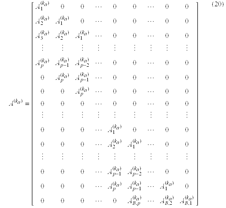
- a ( k a ) [ A 1 ( k a ) 0 0 ⁇ 0 0 ⁇ 0 0 A 2 ( k a ) A 1 ( k a ) 0 ⁇ 0 0 ⁇ 0 0 A 3 ( k a ) A 2 ( k a ) A 1 ( k a ) ⁇ 0 0 ⁇ 0 ⁇ 0 ⁇ ⁇ ⁇ A p ( k a ) A p - 1 ( k a ) A p - 2 ( k a ) ⁇ 0 0 ⁇ 0 0 A p ( k a ) A p - 1 ( k a ) ⁇ 0 0 ⁇ 0 0 A p ( k a ) A p - 1 ( k a ) ⁇ 0 0 ⁇ 0 0 0 0 A p ( k a ) A p - 1 ( k
- the received noisy signal vector e can then be presented by
- a m [ A m ( 1 ) A m ( 1 ) ⁇ A m ( k a ) ]
- a B , m [ A B , m ( 1 ) A B , m ( 1 ) ⁇ A B , m ( k a ) ]
- ⁇ m 1 , ... ⁇ , p ( 22 )
- a 1 and A B,1 given in Eq.(22) form the corresponding sub-system matrices.
- two iteration procedures are proposed for estimating the transmitted data symbol vector d based on the sub-system form of Eq.(29); one is called forward propagation multiuser joint detection (FPMJD), the other is called forward-backward propagation multiuser joint detection (FBPMJD).
- FPMJD forward propagation multiuser joint detection
- FBPMJD forward-backward propagation multiuser joint detection
- M (FP) is a forward propagation estimate operator.
- ZF zero-forcing
- the noise and the transmitted symbols are uncorrelated, i.e., the noise covariance matrix, denoted as R n , and the transmitted symbol covariance matrix, denoted as R d , are in the form of
- I is the identity matrix
- ⁇ n 2 and ⁇ d 2 are the noise and symbol variances, respectively.
- decoder 403 utilizes a FPMJD iterative procedure to estimate d n as follows:
- M (FP) is the estimate operator defined in Eq.(30) or Eq.(35).
- FBP forward-backward propagation
- the system in Eq.(41) characterizes a backward propagation procedure for data symbol estimation, so the data symbol estimation operator of the system is called a backward propagation estimate operator denoted as M (BP) .
- M (BP) ( B H ⁇ B ) - 1 ⁇ B H ⁇ ⁇ M B
- ZF ( BP ) ( B B H ⁇ B B ) - 1 ⁇ B B H ( 42 )
- Eq.(43) or Eq.(45) is based on knowing vectors an, which, in the preferred embodiment, can be obtained by decoder 403 through the forward propagation procedure (FP). That is, solving Eq.(43) or Eq.(45) actually involves two procedures: the forward propagation procedure characterized by Eq.(29) and the backward propagation procedure characterized by Eq.(41). We hence call the resulted solution of Eq.(41) the forward-backward solution.
- the detailed description to get the forward-backward solution d ⁇ ⁇ n , n 1 , ⁇ ⁇ , N ,
Landscapes
- Engineering & Computer Science (AREA)
- Computer Networks & Wireless Communication (AREA)
- Signal Processing (AREA)
- Physics & Mathematics (AREA)
- Mathematical Physics (AREA)
- Mobile Radio Communication Systems (AREA)
- Digital Transmission Methods That Use Modulated Carrier Waves (AREA)
Abstract
Description


Claims (3)


Priority Applications (6)
| Application Number | Priority Date | Filing Date | Title |
|---|---|---|---|
| US09/020,970 US6339612B1 (en) | 1998-02-09 | 1998-02-09 | Method and apparatus for joint detection of data in a direct sequence spread spectrum communications system |
| JP2000530994A JP4359388B2 (en) | 1998-02-09 | 1998-11-13 | Method and apparatus for joint detection of data in a direct sequence spread spectrum communication system |
| PCT/US1998/024367 WO1999040698A1 (en) | 1998-02-09 | 1998-11-13 | Method and apparatus for joint detection of data in a direct sequence spread spectrum communications system |
| EP98965960A EP1068688A4 (en) | 1998-02-09 | 1998-11-13 | Method and apparatus for joint detection of data in a direct sequence spread spectrum communications system |
| BR9814805-2A BR9814805A (en) | 1998-02-09 | 1998-11-13 | Method and apparatus for the joint detection of data in a spread spectrum communication system of direct sequence |
| KR1020007008672A KR100343088B1 (en) | 1998-02-09 | 1998-11-13 | Method and apparatus for joint detection of data in a direct sequence spread spectrum communications system |
Applications Claiming Priority (1)
| Application Number | Priority Date | Filing Date | Title |
|---|---|---|---|
| US09/020,970 US6339612B1 (en) | 1998-02-09 | 1998-02-09 | Method and apparatus for joint detection of data in a direct sequence spread spectrum communications system |
Publications (1)
| Publication Number | Publication Date |
|---|---|
| US6339612B1 true US6339612B1 (en) | 2002-01-15 |
Family
ID=21801610
Family Applications (1)
| Application Number | Title | Priority Date | Filing Date |
|---|---|---|---|
| US09/020,970 Expired - Lifetime US6339612B1 (en) | 1998-02-09 | 1998-02-09 | Method and apparatus for joint detection of data in a direct sequence spread spectrum communications system |
Country Status (6)
| Country | Link |
|---|---|
| US (1) | US6339612B1 (en) |
| EP (1) | EP1068688A4 (en) |
| JP (1) | JP4359388B2 (en) |
| KR (1) | KR100343088B1 (en) |
| BR (1) | BR9814805A (en) |
| WO (1) | WO1999040698A1 (en) |
Cited By (50)
| Publication number | Priority date | Publication date | Assignee | Title |
|---|---|---|---|---|
| US20010024426A1 (en) * | 2000-02-04 | 2001-09-27 | Ariela Zeira | Support of multiuser detection in the downlink |
| US20010036200A1 (en) * | 2000-02-07 | 2001-11-01 | Tantivy Communications, Inc. | Minimal maintenance link to support synchronization |
| US20020006119A1 (en) * | 2000-02-29 | 2002-01-17 | Ville Steudle | Defining measurement gaps in inter-frequency measurement |
| US20020080742A1 (en) * | 1997-12-17 | 2002-06-27 | Tantivy Communications, Inc. | System and method for maintaining timing of synchronization messages over a reverse link of a CDMA wireless communication system |
| US20020101845A1 (en) * | 2000-12-13 | 2002-08-01 | Interdigital Technology Corporation | Modified block space time transmit diversity encoder |
| US20020136334A1 (en) * | 2000-07-21 | 2002-09-26 | Takayuki Nagayasu | Receiver for wireless communication |
| US20020173298A1 (en) * | 2001-03-30 | 2002-11-21 | Bernardo Elayda | Wireless programmable logic devices |
| US20030095585A1 (en) * | 2001-06-01 | 2003-05-22 | Samsung Electronics Co., Ltd. | Method and apparatus for downlink joint detection in a communication system |
| US6584116B1 (en) * | 1998-04-28 | 2003-06-24 | Alcatel | Method of transmission in a UMTS mobile telephone network enabling preparation for handover to a GSM cell during a call in a UMTS cell |
| US6603749B1 (en) * | 1998-10-27 | 2003-08-05 | Robert Bosch Gmbh | Method for estimation of an impulse response of a signal transmission channel and mobile station |
| US20030179812A1 (en) * | 2002-03-19 | 2003-09-25 | Nick Carbone | T-spaced equalization for 1xEV systems |
| US20030210754A1 (en) * | 2002-05-09 | 2003-11-13 | Interdigital Technology Corporation | Method and apparatus for parallel midamble cancellation |
| US6674732B1 (en) * | 1998-02-13 | 2004-01-06 | Sony Corporation | Transmitting method, receiving method, transmitter, and receiver |
| US20040013213A1 (en) * | 2002-07-18 | 2004-01-22 | Hao Bi | Receiver for and method of recovering transmitted symbols in a H-ARQ packet retransmission |
| US20040165567A1 (en) * | 1999-09-21 | 2004-08-26 | Interdigital Technology Corporation | Multiuser detector for variable spreading factors |
| US6788669B1 (en) * | 1999-02-26 | 2004-09-07 | Mitsubishi Denki Kabushiki Kaisha | CDMA demodulating apparatus and method and CDMA mobile communication system |
| US6804206B1 (en) * | 1999-05-07 | 2004-10-12 | Koninklijke Philips Electronics N.V. | Radio communication system |
| US6810023B1 (en) * | 1998-02-27 | 2004-10-26 | Siemens Aktiengesellschaft | Method and radio communications system for transmitting information between a base station and other radio stations |
| US20040233875A1 (en) * | 1999-07-05 | 2004-11-25 | Matsushita Electric Industrial Co., Ltd. | Base station apparatus in a CDMA communication system |
| US6831944B1 (en) * | 1999-09-14 | 2004-12-14 | Interdigital Technology Corporation | Reduced computation in joint detection |
| US20040252793A1 (en) * | 2003-06-14 | 2004-12-16 | Lg Electronics Inc. | Channel estimation method and apparatus |
| US20050002356A1 (en) * | 2001-09-18 | 2005-01-06 | Interdigital Technology Corporation | Method and apparatus employed in a user equipment for interference signal code power and noise variance estimation |
| US20050111405A1 (en) * | 2003-11-25 | 2005-05-26 | Emmanuel Kanterakis | Interference cancellation method and apparatus |
| US20050201319A1 (en) * | 2004-02-17 | 2005-09-15 | Samsung Electronics Co., Ltd. | Method for transmission of ACK/NACK for uplink enhancement in a TDD mobile communication system |
| US7009958B1 (en) * | 2000-05-19 | 2006-03-07 | At&T Corp. | Unified encoding process for generalized multiple access |
| US7099413B2 (en) * | 2000-02-07 | 2006-08-29 | At&T Corp. | Method for near optimal joint channel estimation and data detection for COFDM systems |
| US20060274711A1 (en) * | 2000-02-07 | 2006-12-07 | Nelson G R Jr | Maintenance link using active/standby request channels |
| CN1295886C (en) * | 2001-02-06 | 2007-01-17 | 美商内数位科技公司 | Low complexity data detection using fast fourier transform of channel correlation matrix |
| WO2007016811A1 (en) * | 2005-08-08 | 2007-02-15 | Zte Corporation | Restrain method for signal interference from users in neighbor cells |
| US20070054621A1 (en) * | 2003-12-23 | 2007-03-08 | Peter Larsson | Advanced multi-sensor processing |
| US20070223426A1 (en) * | 1998-06-01 | 2007-09-27 | Tantivy Communications, Inc. | Transmittal of heartbeat signal at a lower lever than heartbeat request |
| US20080016256A1 (en) * | 1999-05-20 | 2008-01-17 | Canon Kabushiki Kaisha | Information processing apparatus, information processing system, operation control method, and storage medium |
| US20080049684A1 (en) * | 2001-05-14 | 2008-02-28 | Interdigital Technology Corporation | TDMA/CDMA user equipment |
| US20080080638A1 (en) * | 2006-09-29 | 2008-04-03 | Analog Devices, Inc. | Method and apparatus for joint detection |
| US7372825B1 (en) * | 1999-07-13 | 2008-05-13 | Texas Instruments Incorporated | Wireless communications system with cycling of unique cell bit sequences in station communications |
| US20080123210A1 (en) * | 2006-11-06 | 2008-05-29 | Wei Zeng | Handling synchronization errors potentially experienced by a storage device |
| US7385617B2 (en) | 2003-05-07 | 2008-06-10 | Illinois Institute Of Technology | Methods for multi-user broadband wireless channel estimation |
| US20080198828A1 (en) * | 1999-09-21 | 2008-08-21 | Interdigital Technology Corporation | Multiuser detector for variable spreading factors |
| US20090086680A1 (en) * | 1997-12-17 | 2009-04-02 | Tantivy Communications, Inc. | Multi-detection of heartbeat to reduce error probability |
| US20090175249A1 (en) * | 2001-02-01 | 2009-07-09 | Ipr Licensing, Inc. | Alternate channel for carrying selected message types |
| US20100208708A1 (en) * | 1998-06-01 | 2010-08-19 | Tantivy Communications, Inc. | System and method for maintaining wireless channels over a reverse link of a cdma wireless communication system |
| US20110019059A1 (en) * | 1998-07-17 | 2011-01-27 | Yoichi Mizutani | Imaging apparatus |
| US20110286541A1 (en) * | 2009-01-28 | 2011-11-24 | Jin Young Chun | Method for Transmitting a Midamble in a Radio Communication System |
| US8437330B2 (en) | 2000-12-01 | 2013-05-07 | Intel Corporation | Antenna control system and method |
| US8638877B2 (en) | 2001-02-01 | 2014-01-28 | Intel Corporation | Methods, apparatuses and systems for selective transmission of traffic data using orthogonal sequences |
| US8908654B2 (en) | 1998-06-01 | 2014-12-09 | Intel Corporation | Dynamic bandwidth allocation for multiple access communications using buffer urgency factor |
| US9014118B2 (en) | 2001-06-13 | 2015-04-21 | Intel Corporation | Signaling for wireless communications |
| US9408216B2 (en) | 1997-06-20 | 2016-08-02 | Intel Corporation | Dynamic bandwidth allocation to transmit a wireless protocol across a code division multiple access (CDMA) radio link |
| US9525923B2 (en) | 1997-12-17 | 2016-12-20 | Intel Corporation | Multi-detection of heartbeat to reduce error probability |
| US11575547B2 (en) * | 2017-06-19 | 2023-02-07 | Nokia Technologies Oy | Data transmission network configuration |
Families Citing this family (18)
| Publication number | Priority date | Publication date | Assignee | Title |
|---|---|---|---|---|
| FR2793363B1 (en) * | 1999-05-04 | 2001-07-06 | France Telecom | METHOD OF JOINT DETECTION OF A SET OF CDMA CODES |
| EP1212842B1 (en) * | 1999-09-14 | 2004-04-28 | Interdigital Technology Corporation | Reduced computation in joint detection |
| GB2359966A (en) * | 2000-03-01 | 2001-09-05 | Roke Manor Research | Post processing of spreading codes in a mobile telecommunications system |
| EP1137201B1 (en) | 2000-03-20 | 2004-05-06 | Mitsubishi Electric Information Technology Centre Europe B.V. | Method for transmitting a word representative of transmission parameters respectively allocated to the mobile stations in communication with a base station |
| GB2360676B (en) * | 2000-03-24 | 2003-12-24 | Roke Manor Research | Improvements in or relating to mobile telecommunications systems |
| EP1404034B1 (en) | 2000-04-04 | 2008-11-26 | Mitsubishi Electric Information Technology Centre Europe B.V. | Base station for transmitting a word representative of the number of spreading codes allocated to the mobile stations in communication with the base station |
| CN1108071C (en) * | 2000-04-11 | 2003-05-07 | 信息产业部电信科学技术研究院 | Signal processing method for terminal in CDMA mobile communication system |
| CN1146156C (en) * | 2000-06-07 | 2004-04-14 | 华为技术有限公司 | Forming method of training sequence in channel evaluation |
| GB2364220A (en) * | 2000-06-28 | 2002-01-16 | Motorola Inc | Encoding information in midamble shifts |
| EP1693971A3 (en) * | 2001-02-06 | 2011-05-18 | Interdigital Technology Corporation | Low complexity data detection using fast fourier transform of channel correlation matrix |
| US6625203B2 (en) * | 2001-04-30 | 2003-09-23 | Interdigital Technology Corporation | Fast joint detection |
| DE10138962B4 (en) * | 2001-08-08 | 2011-05-12 | Rohde & Schwarz Gmbh & Co. Kg | Method for detecting active code sequences |
| FR2828615B1 (en) * | 2001-08-10 | 2005-12-02 | Thales Sa | METHOD FOR INCREASING THE FLOW IN A COMMUNICATION SYSTEM |
| KR100391292B1 (en) * | 2001-09-12 | 2003-07-12 | 한국전자통신연구원 | A channel estimation apparatus and method in time division duplexing system |
| NL1020215C2 (en) * | 2002-03-20 | 2003-09-29 | Univ Delft Tech | Communication system for wireless communication using aperiodic codes. |
| CN1555625A (en) * | 2002-04-05 | 2004-12-15 | 连宇通信有限公司 | Coding method having intergroup zero correlabion window characteristic for spread code |
| EP1552405B1 (en) | 2002-08-20 | 2009-06-03 | Interdigital Technology Corporation | Efficient joint detection |
| EP1564901A1 (en) * | 2004-02-16 | 2005-08-17 | Siemens Mobile Communications S.p.A. | A method of joint detection in CDMA-based mobile communication systems |
Citations (6)
| Publication number | Priority date | Publication date | Assignee | Title |
|---|---|---|---|---|
| US4425639A (en) * | 1981-01-12 | 1984-01-10 | Bell Telephone Laboratories, Incorporated | Satellite communications system with frequency channelized beams |
| US5291475A (en) * | 1992-03-27 | 1994-03-01 | Motorola, Inc. | Slot hopped FD/TD/CDMA |
| US5506861A (en) | 1993-11-22 | 1996-04-09 | Ericsson Ge Mobile Comminications Inc. | System and method for joint demodulation of CDMA signals |
| US5542101A (en) * | 1993-11-19 | 1996-07-30 | At&T Corp. | Method and apparatus for receiving signals in a multi-path environment |
| US5790598A (en) * | 1996-03-01 | 1998-08-04 | Her Majesty The Queen In Right Of Canada | Block decision feedback equalizer |
| US5970060A (en) * | 1995-10-06 | 1999-10-19 | Siemens Aktiengesellschaft | Method and system for radio transmission of digital signals |
-
1998
- 1998-02-09 US US09/020,970 patent/US6339612B1/en not_active Expired - Lifetime
- 1998-11-13 JP JP2000530994A patent/JP4359388B2/en not_active Expired - Fee Related
- 1998-11-13 EP EP98965960A patent/EP1068688A4/en not_active Withdrawn
- 1998-11-13 WO PCT/US1998/024367 patent/WO1999040698A1/en not_active Application Discontinuation
- 1998-11-13 BR BR9814805-2A patent/BR9814805A/en not_active Application Discontinuation
- 1998-11-13 KR KR1020007008672A patent/KR100343088B1/en not_active IP Right Cessation
Patent Citations (7)
| Publication number | Priority date | Publication date | Assignee | Title |
|---|---|---|---|---|
| US4425639A (en) * | 1981-01-12 | 1984-01-10 | Bell Telephone Laboratories, Incorporated | Satellite communications system with frequency channelized beams |
| US5291475A (en) * | 1992-03-27 | 1994-03-01 | Motorola, Inc. | Slot hopped FD/TD/CDMA |
| US5291475B1 (en) * | 1992-03-27 | 1995-06-27 | Motorola Inc | Slot hopped fd/td/cmda |
| US5542101A (en) * | 1993-11-19 | 1996-07-30 | At&T Corp. | Method and apparatus for receiving signals in a multi-path environment |
| US5506861A (en) | 1993-11-22 | 1996-04-09 | Ericsson Ge Mobile Comminications Inc. | System and method for joint demodulation of CDMA signals |
| US5970060A (en) * | 1995-10-06 | 1999-10-19 | Siemens Aktiengesellschaft | Method and system for radio transmission of digital signals |
| US5790598A (en) * | 1996-03-01 | 1998-08-04 | Her Majesty The Queen In Right Of Canada | Block decision feedback equalizer |
Non-Patent Citations (7)
| Title |
|---|
| Blanz J., Klein A., Nashan M., Steil A., "Performance of a Cellular Hybrid C/TDMA Mobile Radio System Applying Joint Detection and Coherent Receiver Antenna Diversity", IEEE J. Sel. Areas Comm. vol. 12, No. 4, May 1994. |
| Blanz, et al., Multi-User Direction of Arrival and Channel Estimation for Time-Slotted CDMA with Joint Detection, IEEE, DSP 97, p. 375-378, Jun. 1997.* |
| Isaacson et al., Analysis of Numerical Method, Dover Publication, Inc., pp. 97-99, 1994.* |
| Jung P., "Joint Detection with Coherent Receiver Antenna Diversity in CDMA Mobile Radio Systems", IEEE Trans. Veh. Tech., vol. 44, No. 1, Feb. 1995. |
| Klein A., Baier P.W., "Linear Unbiased Data Estimation in Mobile Radio Systems Applying CDMA", IEEE J. Sel. Areas Comm., vol. 11, No. 7, Sep. 1993. |
| Lupas R., Verdu S., "Linear Multiuser Detectors for Synchronous Code Division Multiple Access Channels", IEEE Trans. Inf. Theory, vol. 35, No. 1, Jan. 1989. |
| Steiner B., Jung P., "Optimum and Sub-optimum Channel Estimation for the Uplink of CDMA Mobile Radio Systems with Joint Detection", by European Trans. Telecom., vol. 5, Jan.-Feb. 1994. |
Cited By (127)
| Publication number | Priority date | Publication date | Assignee | Title |
|---|---|---|---|---|
| US9408216B2 (en) | 1997-06-20 | 2016-08-02 | Intel Corporation | Dynamic bandwidth allocation to transmit a wireless protocol across a code division multiple access (CDMA) radio link |
| US9525923B2 (en) | 1997-12-17 | 2016-12-20 | Intel Corporation | Multi-detection of heartbeat to reduce error probability |
| US20020080742A1 (en) * | 1997-12-17 | 2002-06-27 | Tantivy Communications, Inc. | System and method for maintaining timing of synchronization messages over a reverse link of a CDMA wireless communication system |
| US7936728B2 (en) | 1997-12-17 | 2011-05-03 | Tantivy Communications, Inc. | System and method for maintaining timing of synchronization messages over a reverse link of a CDMA wireless communication system |
| US20090086680A1 (en) * | 1997-12-17 | 2009-04-02 | Tantivy Communications, Inc. | Multi-detection of heartbeat to reduce error probability |
| US9042400B2 (en) | 1997-12-17 | 2015-05-26 | Intel Corporation | Multi-detection of heartbeat to reduce error probability |
| US6674732B1 (en) * | 1998-02-13 | 2004-01-06 | Sony Corporation | Transmitting method, receiving method, transmitter, and receiver |
| US6810023B1 (en) * | 1998-02-27 | 2004-10-26 | Siemens Aktiengesellschaft | Method and radio communications system for transmitting information between a base station and other radio stations |
| US6584116B1 (en) * | 1998-04-28 | 2003-06-24 | Alcatel | Method of transmission in a UMTS mobile telephone network enabling preparation for handover to a GSM cell during a call in a UMTS cell |
| US8792458B2 (en) * | 1998-06-01 | 2014-07-29 | Intel Corporation | System and method for maintaining wireless channels over a reverse link of a CDMA wireless communication system |
| US20070223426A1 (en) * | 1998-06-01 | 2007-09-27 | Tantivy Communications, Inc. | Transmittal of heartbeat signal at a lower lever than heartbeat request |
| US9307532B2 (en) | 1998-06-01 | 2016-04-05 | Intel Corporation | Signaling for wireless communications |
| US20100208708A1 (en) * | 1998-06-01 | 2010-08-19 | Tantivy Communications, Inc. | System and method for maintaining wireless channels over a reverse link of a cdma wireless communication system |
| US8134980B2 (en) | 1998-06-01 | 2012-03-13 | Ipr Licensing, Inc. | Transmittal of heartbeat signal at a lower level than heartbeat request |
| US8908654B2 (en) | 1998-06-01 | 2014-12-09 | Intel Corporation | Dynamic bandwidth allocation for multiple access communications using buffer urgency factor |
| US8139546B2 (en) * | 1998-06-01 | 2012-03-20 | Ipr Licensing, Inc. | System and method for maintaining wireless channels over a reverse link of a CDMA wireless communication system |
| US8248506B2 (en) | 1998-07-17 | 2012-08-21 | Sony Corporation | Imaging apparatus |
| US9210340B2 (en) | 1998-07-17 | 2015-12-08 | Sony Corporation | Imaging apparatus |
| US8830355B2 (en) | 1998-07-17 | 2014-09-09 | Sony Corporation | Imaging apparatus |
| US20110019059A1 (en) * | 1998-07-17 | 2011-01-27 | Yoichi Mizutani | Imaging apparatus |
| US9628710B2 (en) | 1998-07-17 | 2017-04-18 | Sony Corporation | Imaging apparatus |
| US6603749B1 (en) * | 1998-10-27 | 2003-08-05 | Robert Bosch Gmbh | Method for estimation of an impulse response of a signal transmission channel and mobile station |
| US6788669B1 (en) * | 1999-02-26 | 2004-09-07 | Mitsubishi Denki Kabushiki Kaisha | CDMA demodulating apparatus and method and CDMA mobile communication system |
| US6804206B1 (en) * | 1999-05-07 | 2004-10-12 | Koninklijke Philips Electronics N.V. | Radio communication system |
| US20080016256A1 (en) * | 1999-05-20 | 2008-01-17 | Canon Kabushiki Kaisha | Information processing apparatus, information processing system, operation control method, and storage medium |
| US20100098046A1 (en) * | 1999-07-05 | 2010-04-22 | Panasonic Corporation | Radio transmission apparatus and radio reception apparatus in a cdma communication system |
| US7656844B2 (en) * | 1999-07-05 | 2010-02-02 | Panasonic Corporation | Radio transmission apparatus and radio reception apparatus in a CDMA communication system |
| US20040233875A1 (en) * | 1999-07-05 | 2004-11-25 | Matsushita Electric Industrial Co., Ltd. | Base station apparatus in a CDMA communication system |
| US8437316B2 (en) | 1999-07-05 | 2013-05-07 | Panasonic Corporation | Radio transmission apparatus and radio reception apparatus in a CDMA communication system |
| US7372825B1 (en) * | 1999-07-13 | 2008-05-13 | Texas Instruments Incorporated | Wireless communications system with cycling of unique cell bit sequences in station communications |
| US8107420B2 (en) | 1999-07-13 | 2012-01-31 | Texas Instruments Incorporated | Wireless communications system with cycling of unique cell bit sequences in station communications |
| US20080170638A1 (en) * | 1999-07-13 | 2008-07-17 | Timothy Schmidl | Wireless Communications System With Cycling Of Unique Cell Bit Sequences In Station Communications |
| US20050094712A1 (en) * | 1999-09-14 | 2005-05-05 | Interdigital Technology Corporation | Reduced computation in joint detection |
| US6831944B1 (en) * | 1999-09-14 | 2004-12-14 | Interdigital Technology Corporation | Reduced computation in joint detection |
| US20080043875A1 (en) * | 1999-09-14 | 2008-02-21 | Interdigital Technology Corporation | Reduced computation in joint detection |
| US7295596B2 (en) | 1999-09-14 | 2007-11-13 | Interdigital Technology Corporation | Reduced computation in joint detection |
| US7778232B2 (en) | 1999-09-21 | 2010-08-17 | Interdigital Technology Corporation | Multiuser detector for variable spreading factors |
| US8116220B2 (en) | 1999-09-21 | 2012-02-14 | Interdigital Technology Corporation | Method for receiving communication signals having differing spreading factors |
| US20090046692A1 (en) * | 1999-09-21 | 2009-02-19 | Interdigital Technology Corporation | Method for receiving communication signals having differing spreading factors |
| US7443828B2 (en) * | 1999-09-21 | 2008-10-28 | Interdigital Technology Corporation | Multiuser detector for variable spreading factors |
| US20080198828A1 (en) * | 1999-09-21 | 2008-08-21 | Interdigital Technology Corporation | Multiuser detector for variable spreading factors |
| US20040165567A1 (en) * | 1999-09-21 | 2004-08-26 | Interdigital Technology Corporation | Multiuser detector for variable spreading factors |
| US6885649B2 (en) * | 2000-02-04 | 2005-04-26 | Interdigital Technology Corporation | Method of multiuser detection with user equipment |
| US20010024426A1 (en) * | 2000-02-04 | 2001-09-27 | Ariela Zeira | Support of multiuser detection in the downlink |
| US20050169198A1 (en) * | 2000-02-04 | 2005-08-04 | Interdigital Technology Corporation | Base station midamble selection |
| US6934271B2 (en) * | 2000-02-04 | 2005-08-23 | Interdigital Technology Corporation | Support of multiuser detection in the downlink |
| US6795417B2 (en) | 2000-02-04 | 2004-09-21 | Interdigital Technology Corporation | User equipment with multiuser detection |
| US20050169216A1 (en) * | 2000-02-04 | 2005-08-04 | Interdigital Technology Corporation | Channelization code determination by a user equipment |
| US20020097698A1 (en) * | 2000-02-04 | 2002-07-25 | Interdigital Technology Corporation | User equipment with multiuser detection |
| US7710928B2 (en) * | 2000-02-04 | 2010-05-04 | Interdigital Technology Corporation | Channelization code determination by a user equipment |
| US20020110099A1 (en) * | 2000-02-04 | 2002-08-15 | Interdigital Technology Corporation | Method of multiuser detection with user equipment |
| US8175120B2 (en) | 2000-02-07 | 2012-05-08 | Ipr Licensing, Inc. | Minimal maintenance link to support synchronization |
| US7099413B2 (en) * | 2000-02-07 | 2006-08-29 | At&T Corp. | Method for near optimal joint channel estimation and data detection for COFDM systems |
| US9301274B2 (en) | 2000-02-07 | 2016-03-29 | Intel Corporation | Minimal maintenance link to support synchronization |
| US9807714B2 (en) | 2000-02-07 | 2017-10-31 | Intel Corporation | Minimal maintenance link to support synchronization |
| US20090080575A1 (en) * | 2000-02-07 | 2009-03-26 | Chuang Justin C | Method for near optimal joint channel estimation and data detection for COFDM systems |
| US8509268B2 (en) | 2000-02-07 | 2013-08-13 | Intel Corporation | Minimal maintenance link to support sychronization |
| US20010036200A1 (en) * | 2000-02-07 | 2001-11-01 | Tantivy Communications, Inc. | Minimal maintenance link to support synchronization |
| US7940852B2 (en) | 2000-02-07 | 2011-05-10 | At&T Intellectual Property Ii, L.P. | Near optimal joint channel estimation and data detection for COFDM systems |
| US20060274711A1 (en) * | 2000-02-07 | 2006-12-07 | Nelson G R Jr | Maintenance link using active/standby request channels |
| US7133382B2 (en) * | 2000-02-29 | 2006-11-07 | Nokia Mobile Phones, Ltd. | Defining measurement gaps in inter-frequency measurement |
| US20020006119A1 (en) * | 2000-02-29 | 2002-01-17 | Ville Steudle | Defining measurement gaps in inter-frequency measurement |
| US7009958B1 (en) * | 2000-05-19 | 2006-03-07 | At&T Corp. | Unified encoding process for generalized multiple access |
| US7123667B2 (en) * | 2000-07-21 | 2006-10-17 | Mitusbishi Denki Kabushiki Kaisha | Receiver for wireless communication |
| US20020136334A1 (en) * | 2000-07-21 | 2002-09-26 | Takayuki Nagayasu | Receiver for wireless communication |
| US8437330B2 (en) | 2000-12-01 | 2013-05-07 | Intel Corporation | Antenna control system and method |
| US9924468B2 (en) | 2000-12-01 | 2018-03-20 | Intel Corporation | Antenna control system and method |
| US9775115B2 (en) | 2000-12-01 | 2017-09-26 | Intel Corporation | Antenna control system and method |
| US9225395B2 (en) | 2000-12-01 | 2015-12-29 | Intel Corporation | Antenna control system and method |
| US20020101845A1 (en) * | 2000-12-13 | 2002-08-01 | Interdigital Technology Corporation | Modified block space time transmit diversity encoder |
| US7095731B2 (en) * | 2000-12-13 | 2006-08-22 | Interdigital Technology Corporation | Modified block space time transmit diversity encoder |
| US8638877B2 (en) | 2001-02-01 | 2014-01-28 | Intel Corporation | Methods, apparatuses and systems for selective transmission of traffic data using orthogonal sequences |
| US9247510B2 (en) | 2001-02-01 | 2016-01-26 | Intel Corporation | Use of correlation combination to achieve channel detection |
| US20090175249A1 (en) * | 2001-02-01 | 2009-07-09 | Ipr Licensing, Inc. | Alternate channel for carrying selected message types |
| US8274954B2 (en) | 2001-02-01 | 2012-09-25 | Ipr Licensing, Inc. | Alternate channel for carrying selected message types |
| US8687606B2 (en) | 2001-02-01 | 2014-04-01 | Intel Corporation | Alternate channel for carrying selected message types |
| CN1295886C (en) * | 2001-02-06 | 2007-01-17 | 美商内数位科技公司 | Low complexity data detection using fast fourier transform of channel correlation matrix |
| US6873842B2 (en) * | 2001-03-30 | 2005-03-29 | Xilinx, Inc. | Wireless programmable logic devices |
| US20020173298A1 (en) * | 2001-03-30 | 2002-11-21 | Bernardo Elayda | Wireless programmable logic devices |
| US20050143022A1 (en) * | 2001-03-30 | 2005-06-30 | Xilinx, Inc. | Wireless programmable logic devices |
| US7480491B2 (en) | 2001-03-30 | 2009-01-20 | Xilinx, Inc. | Wireless programmable logic devices |
| US20080049684A1 (en) * | 2001-05-14 | 2008-02-28 | Interdigital Technology Corporation | TDMA/CDMA user equipment |
| US8509195B2 (en) | 2001-05-14 | 2013-08-13 | Interdigital Technology Corporation | TDMA/CDMA user equipment |
| US8169979B2 (en) * | 2001-05-14 | 2012-05-01 | Interdigital Technology Corporation | TDMA/CDMA user equipment |
| US10334593B2 (en) | 2001-05-14 | 2019-06-25 | Interdigital Technology Corporation | Hybrid apparatus using physical channels |
| US9674834B2 (en) | 2001-05-14 | 2017-06-06 | Interdigital Technology Corporation | Hybrid apparatus using physical channels |
| US20030095585A1 (en) * | 2001-06-01 | 2003-05-22 | Samsung Electronics Co., Ltd. | Method and apparatus for downlink joint detection in a communication system |
| US7161972B2 (en) * | 2001-06-01 | 2007-01-09 | Samsung Electronics Co., Ltd. | Method and apparatus for downlink joint detection in a communication system |
| US9014118B2 (en) | 2001-06-13 | 2015-04-21 | Intel Corporation | Signaling for wireless communications |
| US7492750B2 (en) * | 2001-09-18 | 2009-02-17 | Interdigital Technology Corporation | Method and apparatus employed in a user equipment for interference signal code power and noise variance estimation |
| US8300520B2 (en) | 2001-09-18 | 2012-10-30 | Interdigital Technology Corporation | Method and apparatus employed in a user equipment for interference signal code power and noise variance estimation |
| US20090168739A1 (en) * | 2001-09-18 | 2009-07-02 | Interdigital Technology Corporation | Method and apparatus employed in a user equipment for interference signal code power and noise variance estimation |
| US20050002356A1 (en) * | 2001-09-18 | 2005-01-06 | Interdigital Technology Corporation | Method and apparatus employed in a user equipment for interference signal code power and noise variance estimation |
| WO2003079759A3 (en) * | 2002-03-19 | 2004-02-26 | Nokia Corp | T-spaced equalization for 1xev systems |
| US20030179812A1 (en) * | 2002-03-19 | 2003-09-25 | Nick Carbone | T-spaced equalization for 1xEV systems |
| US6856646B2 (en) * | 2002-03-19 | 2005-02-15 | Nokia Corporation | T-spaced equalization for 1xEV systems |
| WO2003079759A2 (en) * | 2002-03-19 | 2003-10-02 | Nokia Corporation | T-spaced equalization for 1xev systems |
| CN100459412C (en) * | 2002-05-09 | 2009-02-04 | 美商内数位科技公司 | Method and apparatus for parallel midamble cancellation |
| US7428278B2 (en) | 2002-05-09 | 2008-09-23 | Interdigital Technology Corporation | Method and apparatus for parallel midamble cancellation |
| US20030210754A1 (en) * | 2002-05-09 | 2003-11-13 | Interdigital Technology Corporation | Method and apparatus for parallel midamble cancellation |
| US20080285692A1 (en) * | 2002-05-09 | 2008-11-20 | Interdigital Technology Corporation | Method and apparatus for parallel midamble cancellation |
| WO2003096589A3 (en) * | 2002-05-09 | 2004-04-01 | Interdigital Tech Corp | Method and apparatus for parallel midamble cancellation |
| KR100926493B1 (en) | 2002-05-09 | 2009-11-12 | 인터디지탈 테크날러지 코포레이션 | Method and apparatus for parallel midamble cancellation |
| US20090316843A1 (en) * | 2002-05-09 | 2009-12-24 | Interdigital Technology Corporation | Method and apparatus for parallel midamble cancellation |
| US7751512B2 (en) | 2002-05-09 | 2010-07-06 | Interdigital Technology Corporation | Method and apparatus for parallel midamble cancellation |
| WO2003096589A2 (en) * | 2002-05-09 | 2003-11-20 | Interdigital Technology Corporation | Method and apparatus for parallel midamble cancellation |
| US7773704B2 (en) | 2002-05-09 | 2010-08-10 | Interdigital Technology Corporation | Method and apparatus for parallel midamble cancellation |
| US7573958B2 (en) | 2002-07-18 | 2009-08-11 | Motorola, Inc. | Receiver for and method of recovering transmitted symbols in a H-ARQ packet retransmission |
| US20040013213A1 (en) * | 2002-07-18 | 2004-01-22 | Hao Bi | Receiver for and method of recovering transmitted symbols in a H-ARQ packet retransmission |
| US7385617B2 (en) | 2003-05-07 | 2008-06-10 | Illinois Institute Of Technology | Methods for multi-user broadband wireless channel estimation |
| US20040252793A1 (en) * | 2003-06-14 | 2004-12-16 | Lg Electronics Inc. | Channel estimation method and apparatus |
| US20050111405A1 (en) * | 2003-11-25 | 2005-05-26 | Emmanuel Kanterakis | Interference cancellation method and apparatus |
| TWI383697B (en) * | 2003-12-23 | 2013-01-21 | Ericsson Telefon Ab L M | Multi-sensor processing |
| US20070054621A1 (en) * | 2003-12-23 | 2007-03-08 | Peter Larsson | Advanced multi-sensor processing |
| US7924949B2 (en) | 2003-12-23 | 2011-04-12 | Telefonaktiebolaget Lm Ericsson (Publ) | Advanced multi-sensor processing |
| US7706477B2 (en) * | 2003-12-23 | 2010-04-27 | Telefonaktiebolaget Lm Ericsson (Publ) | Advanced multi-sensor processing |
| US20100098014A1 (en) * | 2003-12-23 | 2010-04-22 | Telefonaktiebolaget Lm Ericsson (Publ) | Advanced multi-sensor processing |
| US20050201319A1 (en) * | 2004-02-17 | 2005-09-15 | Samsung Electronics Co., Ltd. | Method for transmission of ACK/NACK for uplink enhancement in a TDD mobile communication system |
| US8213354B2 (en) * | 2004-02-17 | 2012-07-03 | Samsung Electronics Co., Ltd | Method for transmission of ACK/NACK for uplink enhancement in a TDD mobile communication system |
| CN101133562B (en) * | 2005-08-08 | 2010-10-13 | 中兴通讯股份有限公司 | Method for restraining user signal interference from neighbor subdistrict |
| WO2007016811A1 (en) * | 2005-08-08 | 2007-02-15 | Zte Corporation | Restrain method for signal interference from users in neighbor cells |
| US7916841B2 (en) * | 2006-09-29 | 2011-03-29 | Mediatek Inc. | Method and apparatus for joint detection |
| US20080080638A1 (en) * | 2006-09-29 | 2008-04-03 | Analog Devices, Inc. | Method and apparatus for joint detection |
| US20080123210A1 (en) * | 2006-11-06 | 2008-05-29 | Wei Zeng | Handling synchronization errors potentially experienced by a storage device |
| US20110286541A1 (en) * | 2009-01-28 | 2011-11-24 | Jin Young Chun | Method for Transmitting a Midamble in a Radio Communication System |
| US8804637B2 (en) * | 2009-01-28 | 2014-08-12 | Lg Electronics Inc. | Method for transmitting a midamble in a radio communication system |
| US11575547B2 (en) * | 2017-06-19 | 2023-02-07 | Nokia Technologies Oy | Data transmission network configuration |
Also Published As
| Publication number | Publication date |
|---|---|
| BR9814805A (en) | 2000-10-17 |
| JP4359388B2 (en) | 2009-11-04 |
| JP2002503057A (en) | 2002-01-29 |
| EP1068688A1 (en) | 2001-01-17 |
| KR100343088B1 (en) | 2002-07-05 |
| EP1068688A4 (en) | 2004-04-07 |
| WO1999040698A1 (en) | 1999-08-12 |
| KR20010040780A (en) | 2001-05-15 |
Similar Documents
| Publication | Publication Date | Title |
|---|---|---|
| US6339612B1 (en) | Method and apparatus for joint detection of data in a direct sequence spread spectrum communications system | |
| KR100842893B1 (en) | Iterative and turbobased method and apparatus for equalization of spreadspectrum downlink channels | |
| KR100759297B1 (en) | Low complexity data detection using fast fourier transform of channel correlation matrix | |
| KR100803682B1 (en) | Efficient multiple input multiple output system for multi-path fading channels | |
| US6574270B1 (en) | Baseband interference canceling spread spectrum communications methods and apparatus | |
| US20120314740A1 (en) | Groupwise successive interference cancellation for block transmission with reception diversity | |
| US7609750B2 (en) | Segment-wise channel equalization based data estimation | |
| US7539238B2 (en) | Extended algorithm data estimator | |
| WO2002039610A2 (en) | Single user detection | |
| JP2002528992A (en) | Signal extraction method in CDMA system | |
| US20030179814A1 (en) | Receiver and method of receiving a cdma signal in presence of interfereres with unknown spreading factors | |
| JP4756134B2 (en) | Decoding method and apparatus | |
| EP1496622B1 (en) | Method and apparatus for detecting active downlink channelization codes in a TD-CDMA mobile communication system | |
| US7298801B2 (en) | Method and device for demodulating signals from multiple users | |
| EP0973283B1 (en) | Probing apparatus and method for a spread-spectrum communications system | |
| Krzymien et al. | Near-far resistant MIMO iterative receiver for uplink LTE | |
| EP1156592A2 (en) | A reception method and a CDMA receiver |
Legal Events
| Date | Code | Title | Description |
|---|---|---|---|
| AS | Assignment |
Owner name: MOTOROLA, INC., ILLINOIS Free format text: ASSIGNMENT OF ASSIGNORS INTEREST;ASSIGNORS:STEWART, KENNETH A.;QIAO, YI;REEL/FRAME:008978/0137 Effective date: 19980209 |
|
| STCF | Information on status: patent grant |
Free format text: PATENTED CASE |
|
| FPAY | Fee payment |
Year of fee payment: 4 |
|
| FPAY | Fee payment |
Year of fee payment: 8 |
|
| AS | Assignment |
Owner name: MOTOROLA MOBILITY, INC, ILLINOIS Free format text: ASSIGNMENT OF ASSIGNORS INTEREST;ASSIGNOR:MOTOROLA, INC;REEL/FRAME:025673/0558 Effective date: 20100731 |
|
| AS | Assignment |
Owner name: MOTOROLA MOBILITY LLC, ILLINOIS Free format text: CHANGE OF NAME;ASSIGNOR:MOTOROLA MOBILITY, INC.;REEL/FRAME:029216/0282 Effective date: 20120622 |
|
| FPAY | Fee payment |
Year of fee payment: 12 |
|
| AS | Assignment |
Owner name: GOOGLE TECHNOLOGY HOLDINGS LLC, CALIFORNIA Free format text: ASSIGNMENT OF ASSIGNORS INTEREST;ASSIGNOR:MOTOROLA MOBILITY LLC;REEL/FRAME:034305/0001 Effective date: 20141028 |