US6339661B1 - Polarization maintaining fiber optic circulators - Google Patents
Polarization maintaining fiber optic circulators Download PDFInfo
- Publication number
- US6339661B1 US6339661B1 US09/693,422 US69342200A US6339661B1 US 6339661 B1 US6339661 B1 US 6339661B1 US 69342200 A US69342200 A US 69342200A US 6339661 B1 US6339661 B1 US 6339661B1
- Authority
- US
- United States
- Prior art keywords
- port
- polarizing beam
- beam splitter
- optical
- disposed
- Prior art date
- Legal status (The legal status is an assumption and is not a legal conclusion. Google has not performed a legal analysis and makes no representation as to the accuracy of the status listed.)
- Expired - Lifetime
Links
Images


Classifications
-
- G—PHYSICS
- G02—OPTICS
- G02B—OPTICAL ELEMENTS, SYSTEMS OR APPARATUS
- G02B6/00—Light guides; Structural details of arrangements comprising light guides and other optical elements, e.g. couplings
- G02B6/24—Coupling light guides
- G02B6/26—Optical coupling means
- G02B6/27—Optical coupling means with polarisation selective and adjusting means
- G02B6/2746—Optical coupling means with polarisation selective and adjusting means comprising non-reciprocal devices, e.g. isolators, FRM, circulators, quasi-isolators
-
- G—PHYSICS
- G02—OPTICS
- G02F—OPTICAL DEVICES OR ARRANGEMENTS FOR THE CONTROL OF LIGHT BY MODIFICATION OF THE OPTICAL PROPERTIES OF THE MEDIA OF THE ELEMENTS INVOLVED THEREIN; NON-LINEAR OPTICS; FREQUENCY-CHANGING OF LIGHT; OPTICAL LOGIC ELEMENTS; OPTICAL ANALOGUE/DIGITAL CONVERTERS
- G02F1/00—Devices or arrangements for the control of the intensity, colour, phase, polarisation or direction of light arriving from an independent light source, e.g. switching, gating or modulating; Non-linear optics
- G02F1/01—Devices or arrangements for the control of the intensity, colour, phase, polarisation or direction of light arriving from an independent light source, e.g. switching, gating or modulating; Non-linear optics for the control of the intensity, phase, polarisation or colour
- G02F1/09—Devices or arrangements for the control of the intensity, colour, phase, polarisation or direction of light arriving from an independent light source, e.g. switching, gating or modulating; Non-linear optics for the control of the intensity, phase, polarisation or colour based on magneto-optical elements, e.g. exhibiting Faraday effect
- G02F1/093—Devices or arrangements for the control of the intensity, colour, phase, polarisation or direction of light arriving from an independent light source, e.g. switching, gating or modulating; Non-linear optics for the control of the intensity, phase, polarisation or colour based on magneto-optical elements, e.g. exhibiting Faraday effect used as non-reciprocal devices, e.g. optical isolators, circulators
Definitions
- the present invention is directed to optical components for use in fiber optic networks and particularly to devices known as optical circulators and more particularly to polarization maintaining fiber optic circulators.
- optical circulators By directing signal flow in the proper direction, optical circulators can reduce system cost and complexity in optical equipment used in fiber optic networks. In complex optical networks, passive optical components are essential elements for sorting and delivering signals to their proper destination. To accomplish this control, the optical-signal flow through the sequential ports of a circulator is guided in a fashion comparable to that of vehicles entering and leaving a traffic circle. A circulator transmits an incoming signal entering Port 1 to Port 2 while transmitting another incoming signal from Port 2 to Port 3, and another from Port 3 to Port 4 etc.
- optical circulators make them indispensable for routing bidirectional optical traffic. Firstly, optical circulators are low-loss devices, unlike splitters that incrementally add 3-dB losses for each device used. Secondly, optical circulators have high adjacent port isolation and eliminate the need for external isolators.
- Optical circulators are also important and enabling components in ADD/DROP applications. Optical circulators are forecast to play a significant role in duplex transmission, optical time domain reflectometry (OTDR) measurement systems, wavelength division/multiplexing (WDM) transmission systems and Erbium (Er) doped fiber amplifiers (EDFA).
- the present invention provides polarization maintaining circulators of a number of embodiments.
- the first embodiment uses birefringent wedges and Faraday rotators and is an inline design, meaning the fibers are all inline with each other. This design is described in a 3 port version, however it can be extended to 4 or more ports. Inline designs are generally more compact, less complex and reduce alignment problems as compared to non-inline designs.
- the second embodiment makes use of a polarizing beam splitting cube and Faraday rotators which results in a design with the fibers being at either 90° or 180° with respect to each other, all in the same plane.
- This second embodiment is limited to a maximum of 4 ports but has the advantage of being a closed design, meaning that light launched from a port will eventually return to that port, for example light launched form port 1 will follow the following sequence: 1 s ⁇ 2 s ⁇ 3 s s ⁇ 4 s ⁇ 1 s , for the fast axis the sequence is slightly different: 1 f ⁇ 4 f ⁇ 3 f ⁇ 2 f ⁇ 1 f . Note that the axes of polarization maintaining optical fibers are referred to as “slow” (or major) and “fast” (which relates to the relative propagation velocities).
- a third embodiment makes use of beam splitter cubes and Faraday rotators, like the second. However the difference is now that instead of having 3 or 4 separate fibers, two fibers are combined into one holder, making this an inline device. This is accomplished by placing a reflector on one or both of the sides of the polarizing beam splitting cube (depending on a 3 or 4 port design).
- the four port design of this embodiment is of the closed variety, meaning that light launched into the slow axis of port 1 will follow the following route: 1 s ⁇ 2 s ⁇ 3 s ⁇ 4 s ⁇ 1 s , light launched into the fast axis of port 1 will follow: 1 f ⁇ 4 f ⁇ 3 f ⁇ 2 f ⁇ 1 f , which is similar to that of the previous design.
- FIGS. 1 a and 1 b illustrates the operation of a birefringent wedges and Faraday rotator unit which forms the optical isolating component of the present invention
- FIGS. 2 a , 2 b and 2 c illustrates the components of a polarization maintaining optical circulator of a first embodiment of the present invention using birefringent wedges;
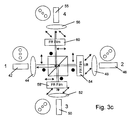
- FIGS. 3 a through 3 c show a second embodiment of a polarization maintaining circulator based on a polarizing beam splitting cube and one or more 45° non-reciprocal Faraday polarization rotating films;
- FIGS. 4 a through 4 e show a third embodiment of an inline polarization maintaining circulator based on a polarizing beam splitting cube and one or more 45° non-reciprocal Faraday polarization rotating films with reflecting surfaces disposed on one or more surfaces of the polarizing beam splitting cube.
- FIG. 1 a and 1 b The principle of operation of the birefringent wedge based circulator is shown in FIG. 1 a and 1 b , a nonreciprocal 45° Faraday rotating film 10 is placed in between two birefringent wedges 12 , 14 having their optical axis at 45° from each other and with the optical axes perpendicular to the direction of light propagation, and with the base of wedge 12 disposed downwardly and the base of wedge 14 disposed upwardly (i.e. one wedge is inverted with respect to the other).
- the optical axis of birefringent wedge 12 is disposed at 90° degrees (i.e. lying in the plane of the paper) and that of birefringent wedge 14 is rotated 45° out of the plane of the paper.
- birefringent wedge 12 splits the input light beam into two orthogonal states of polarization, extraordinary “E” and ordinary “O” beams.
- Faraday rotating film 10 rotates both “E” and “O” beams by 45°. Because the optic axis of birefringent wedge 14 is at 45° from the wedge 12 , the “E” and “O” polarizations travel through birefringent wedge 14 as “E” and “O” (i.e. they maintain their respective input polarization state with respect to wedge 14 ) and therefore exit wedge 14 in a direction parallel to each other.
- birefringent wedge 14 splits the beam in two orthogonal (“E” and “O”) polarizations.
- E orthogonal
- O orthogonal
- Suitable birefringent materials for wedges 14 , 16 include, but are not limited to, lithium niobate (LiNbO 3 ), rutile (TiO 2 ), and yttrium vanadate (YVO 4 ).
- FIGS. 2 a to 2 c The first embodiment of an inline polarization maintaining (PM) circulator based on birefringent wedges 12 , 14 and Faraday rotator 10 of FIG. 1 is illustrated in FIGS. 2 a to 2 c .
- a collimating lens 18 is used at the input end to couple light from and into two adjacent polarization maintaining fibers 20 , 22 representing ports 1 and 3 respectively.
- An output collimating lens 24 couples light into two adjacent polarization maintaining fibers 26 , 28 representing ports 2 and 4 respectively.
- the slow axis (or major axis) of input polarization maintaining fiber 20 is aligned parallel to the optic axis of birefringent wedge 12 .
- the slow axis of output polarization maintaining fiber 26 (port 2) is oriented perpendicular the optic axis of the second birefringent wedge 14 .
- Fiber 22 of Port 3 has its slow axis perpendicular to the optic axis of birefringent wedge 12 and fiber 28 of Port 4 has its slow axis perpendicular to the optic axis of birefringent wedge 14 .
- Light is transmitted from port 1 to port 2 (but not into port 3), from port 2 into port 3 (but not into port 1) and from port 3 into port 4 (but not into port 2).
- the actual direction of orientation of the optical axes of birefringent wedges 14 , 16 is not critical as long as the optical axes of the two wedges are at 45° from each other, perpendicular to the light propagation direction and aligned with their respective input and output fibers.
- Collimating lenses 16 , 20 may be of the usual types used in fiber optic systems such as graded index (GRIN) lenses.
- FIG. 2 a shows the path from port 1 to port 2 which path is the same as that shown in FIG. 1 a . If an “E” beam is coming from port 1, it will be collimated into the device and enter the first birefringent wedge 12 . In this direction the polarization states, with respect to the birefringent wedges, are preserved and therefore no angular deviation of the beam will take place, resulting in the beam staying parallel to the beam launched from port 1. This light will now be focused into fiber 26 at port 2 .
- FIG. 2 b shows the path from port 1 to port 2 which path is the same as the reverse path shown in FIG.
- FIG. 2 c shows the path from port 3 to port 4, in this path light from fiber 22 will be collimated by lens 18 and enter wedge 12 at an angle, in this path the light will exit wedge 14 at an angle, but still parallel to the beam launched from port 3, so as to intercept fiber 28 of port 4 but not fiber 26 of port 2.
- Excessive insertion loss can be the result of tolerances in the components, such as wedge angle, lens focal lengths, and fiber separation (distance between the fiber cores on the 2 fiber side of the device). These tolerances can be compensated for by tilting (tipping) the wedges in the plane defined by the in angle separated “O” and “E” beams (see angle ⁇ in FIG. 2 b ). This tilting will have the result of changing the angle between the “O” and “E” beams and therefore compensating for the above-mentioned tolerances. Another way of compensating for these tolerances is by using compound lenses, in which the focal length can be varied. This will also have the desired compensating effect.
- the circulators described herein have used polarization maintaining input and output fibers with their optic axes aligned with the optic axes of their respective birefringent wedges. This OA alignment assures maximum performance of the circulators by eliminating power coupling from one polarization state to the other and therefor power coupling between the fiber ports. However the use of a single mode fibers, in certain applications, may provide adequate performance.
- FIGS. 3 a through 3 c show a polarization maintaining circulator based on a polarizing beam splitting cube and one or more 45° non-reciprocal Faraday rotating films (referred to as FR films), the number of FR films is determined by the number of fiber ports and type of circulator (open or closed).depending on the number of ports desired. For a three port circulator, one Faraday rotator film is used. For a four port circulator, two Faraday rotator films are used. For a closed loop four port circulator, three Faraday rotator films are used. In all cases, at each port a polarization maintaining fiber and a lens are used for collimating the optical beam into the beam splitting cube and coupling into the respective output ports. For ease of assembly, the optical path lengths (OPL) between lenses is set at twice the focal length (f) of these lenses, so the OPL from 1 to 2 is 2f, from 2 to 3 is also 2f etc.
- OPL optical path lengths
- a three port circulator is illustrated in FIG. 3 a and includes a polarizing beam splitting cube 40 (or a polarizing beam splitting film mounted diagonally) and three ports.
- Port one includes an input polarization maintaining fiber 42 and a collimating lens 44
- port two includes a polarization maintaining fiber 46 and collimating lens 48
- port three includes a polarization maintaining fiber 50 and a collimating lens 52 .
- a Faraday rotator film 54 is placed in the optical path leading to port 2 after polarizing beam splitting cube 40 .
- fiber 46 of port 2 is aligned with its slow axis at 45° from input fiber 42
- fiber 50 of port 3 is aligned with its slow axis at 45° from the polarization maintaining fiber of port 2.
- the principle of operation of the three port polarization maintaining circulator of FIG. 3 a is as follows: P (light launched along the slow or major axis of the PM fiber 42 ) polarized light from fiber 42 of port 1 passes through polarizing beam splitting cube (PBSC) 40 , is rotated 45° by Faraday rotator film 54 , and is focused by lens 48 on fiber 46 of port 2 (which has its slow axis parallel to the polarization of incoming beam which is at 45° from the input). This completes the port 1 to port 2 path.
- PBSC polarizing beam splitting cube
- a beam from fiber 46 of port 2 goes through Faraday rotator film 54 thus entering polarizing beam splitting cube 40 as S polarized and is reflected at the polarizing beam splitting cube's 40 diagonal 41 towards port 3 where it is focused by lens 52 on to fiber 50 of port 3.
- No light from port 2 is transmitted to port 1.
- the slow axis of fiber 50 of port 3 is aligned parallel to the incoming S polarization. This completes the path of port 2 to 3.
- Light launched from fiber 50 of port 3 will either couple back into fiber 46 of port 2 or be lost, depending on the polarization state.
- FIG. 3 b illustrates this version of the proposed polarization maintaining circulator in an open loop four port configuration.
- the same reference numbers as those of FIG. 3 a are used to identify the same components, with the addition of a fourth port having a polarization maintaining fiber 55 and a collimating lens 56 a second Faraday rotator film 58 is placed in the optical path leading to port 3 after polarizing beam splitting cube 40 .
- a beam from port 2 goes through Faraday rotator film 54 thus entering polarizing beam splitting cube 40 as S polarized and is reflected at diagonal 41 towards port 3 where it passes through second Faraday rotator film 58 thus rotating the polarization by an additional 45° and is focused by lens 52 on to fiber 50 of port 3.
- No light from port 2 is transmitted to port 1.
- the slow axis of fiber 50 of port 3 is aligned parallel to the incoming polarization which is at 45° (Note the different orientation of fiber 50 from FIGS. 3a to 3 b). This completes the path of port 2 to 3.
- a beam from port 3 goes through Faraday rotator film 58 and is rotated by 45° thus making it a P polarized beam as it enters the polarizing beam splitting cube 40 .
- the P polarized beam passes straight through polarizing beam splitting cube 40 towards port 4 where it is coupled into polarization maintaining fiber 55 of port 4 by lens 56 .
- the slow axis of the polarization maintaining fiber 55 of port 4 is aligned parallel to the incoming P polarization. This completes the path of port 3 to 4.
- FIG. 3 c A closed loop four port circulator is illustrated in FIG. 3 c , which has the same components as that of FIG. 3 b with the addition of a third Faraday rotator film 60 placed in the optical path leading to port 4 after polarizing bean splitting cube 40 .
- the alignment of the fibers of this configuration is the same as that of FIG. 3 b with the exception of fiber 55 of port 4 is aligned with its slow axis at 90° from fiber 50 of port 3 as a beam traveling from port 3 to port 4 will be rotated twice by 45° by Faraday rotators 58 and 60 .
- the port order will differ depending upon the polarization of the light input in port 1.
- the port sequence is: 1 s ⁇ 2 s ⁇ 2 s ⁇ 3 s s ⁇ 1 s .
- the sequence will be: 1 f ⁇ 4 f ⁇ 3 f ⁇ 2 f ⁇ 1 f .
- FIGS. 4 a - 4 e illustrate a four port polarization maintaining fiber optic closed loop circulator 70 .
- This version of a polarization maintaining circulator is based on the use of a polarizing beam splitter cube 72 (PBSC) with reflective coatings 74 , 76 on the surfaces that are perpendicular to the light paths.
- Circulator 70 includes polarization maintaining fibers 78 , 80 forming ports 1 and 2, and polarization maintaining fibers 82 , 84 forming ports 3 and 4 respectively.
- PBSC polarizing beam splitter cube 72
- a collimating lens 86 and a 45° Faraday polarization rotator (FR) 88 is placed between ports 1 and 2 and polarizing beam splitter cube 72 and collimating lens 90 and a 45° Faraday rotator 92 is placed between ports 3 and 4 and polarizing beam splitter cube 72 .
- the orientation of the polarization maintaining fibers 78 , 80 , 82 and 84 is shown in the drawings and is such that the polarization alignment from one fiber to the other is maintained, if desired other orientations of the fibers can be used.
- FIG. 4 b illustrates the light path from port 1 to port 2, light launched from fiber 78 of port 1 (slow axis) is collimated and passes through lens 86 and Faraday rotator 88 , for this polarization state (S state with respect to polarizing beam splitter cube 72 ) polarizing beam splitter cube 72 will reflect the light at the 45° beam splitting surface to the surface of mirror 76 , and again at the beam splitting surface. If the condition of the optical path length from the lens to the mirror is one focal length of the lens used and fibers 1 and 2 are positioned correctly with respect to the lens, the light will reflect back into fiber 2 (and the polarization state will be aligned with the slow axis of fiber 2).
- FIG. 4 c illustrates the light path from port 2 to port 3
- light launched from fiber 80 of port 2 will enter the polarizing beam splitter cube 72 in the P state, due to Faraday rotator 88 and thus be transmitted instead of reflected and so couple into fiber 82 of port 3.
- FIG. 4 d illustrates the light path from port 3 to port 4, light launched from fiber 82 of port 3 (slow axis) will enter the polarizing beam splitter cube 72 in the S state and reflect from the beam splitting surface, mirror 74 and the beam spitting surface again into fiber 84 of port 4.
- FIG. 4 c illustrates the light path from port 2 to port 3
- light launched from fiber 80 of port 2 still in the slow axis
- FIG. 4 d illustrates the light path from port 3 to port 4
- light launched from fiber 82 of port 3 slow axis
- FIG. 4 e illustrates the light path from port 4 to port 1 to complete the closed loop
- light launched from fiber 84 of port 4 will enter the polarizing beam splitter cube 72 which will transmit again and couple into fiber 80 of port 1.
- light launched into the slow axis of port 1 will follow the following route: 1 s ⁇ 2 s ⁇ 3 s ⁇ 4 s ⁇ 1 s
- light launched into the fast axis of fiber 1 will follow: 1 f ⁇ 4 f ⁇ 3 f ⁇ 2 f ⁇ 1 f .
- the four port closed loop design described above can readily be converted into a three port open loop configuration by omitting the fourth port and mirror 74 .
- FR film 92 can also be omitted for the 3 port design, however light launched from port 3 will then couple back into port 2.
- the most efficient design places the reflecting surfaces on the faces of the polarizing beam splitter cube. However, the reflecting surfaces can also be in the form of separate mirrors.
Abstract
Description
Claims (19)
Priority Applications (1)
| Application Number | Priority Date | Filing Date | Title |
|---|---|---|---|
| US09/693,422 US6339661B1 (en) | 1999-10-20 | 2000-10-20 | Polarization maintaining fiber optic circulators |
Applications Claiming Priority (2)
| Application Number | Priority Date | Filing Date | Title |
|---|---|---|---|
| US16051499P | 1999-10-20 | 1999-10-20 | |
| US09/693,422 US6339661B1 (en) | 1999-10-20 | 2000-10-20 | Polarization maintaining fiber optic circulators |
Publications (1)
| Publication Number | Publication Date |
|---|---|
| US6339661B1 true US6339661B1 (en) | 2002-01-15 |
Family
ID=26856951
Family Applications (1)
| Application Number | Title | Priority Date | Filing Date |
|---|---|---|---|
| US09/693,422 Expired - Lifetime US6339661B1 (en) | 1999-10-20 | 2000-10-20 | Polarization maintaining fiber optic circulators |
Country Status (1)
| Country | Link |
|---|---|
| US (1) | US6339661B1 (en) |
Cited By (29)
| Publication number | Priority date | Publication date | Assignee | Title |
|---|---|---|---|---|
| US20020168128A1 (en) * | 2001-02-26 | 2002-11-14 | Jds Uniphase Corporation | Optical circulator |
| US20030193716A1 (en) * | 2002-04-09 | 2003-10-16 | Wei-Zhong Li | Three-port circulator |
| US6636651B2 (en) * | 2001-06-08 | 2003-10-21 | Koncent Communication, Inc. | Four-port bidirectional optical circulator |
| US6704469B1 (en) * | 2000-09-12 | 2004-03-09 | Finisar Corporation | Polarization beam combiner/splitter |
| US20040070827A1 (en) * | 2002-10-15 | 2004-04-15 | Wei-Zhong Li | Reflective variable attenuator and tap monitor |
| US6836575B1 (en) | 2002-06-04 | 2004-12-28 | Oplink Communications, Inc. | Three-port PM circular having isolation function |
| US20050008277A1 (en) * | 2000-07-17 | 2005-01-13 | Ping Xie | Fiber optic pair with pigtail geometry |
| US6847486B2 (en) * | 2001-12-14 | 2005-01-25 | Agilent Technologies, Inc | Low-PDL beam splitter |
| US20050018967A1 (en) * | 2002-07-10 | 2005-01-27 | Yonglin Huang | Plug-in module for providing bi-directional data transmission |
| US6882759B1 (en) * | 2002-06-04 | 2005-04-19 | Oplink Communications, Inc. | Four-port PM circulator |
| US6900933B1 (en) | 2002-04-23 | 2005-05-31 | Oplink Communications, Inc. | Integrated two-pump combiner for optical fiber amplifiers |
| US6954307B2 (en) * | 2002-02-12 | 2005-10-11 | Oplink Communications, Inc. | Four-port PM circulator |
| US20050231786A1 (en) * | 2003-02-04 | 2005-10-20 | Fujitsu Limited | Variable optical delay circuit |
| US6987896B1 (en) | 2002-04-09 | 2006-01-17 | Oplink Communications, Inc. | Optical isolator |
| US20060044650A1 (en) * | 2004-08-27 | 2006-03-02 | Liren Du | Low insertion loss circulator |
| US7039278B1 (en) * | 2002-07-10 | 2006-05-02 | Finisar Corporation | Single-fiber bi-directional transceiver |
| US20070056387A1 (en) * | 2003-11-14 | 2007-03-15 | Hajime Obikawa | Torque measuring device |
| US20080025348A1 (en) * | 2006-07-28 | 2008-01-31 | Kuksenkov Dmitri Vladislavovic | High energy, ultrashort pulse ring fiber laser having a linear dispersion compensator with chirped Bragg gratings |
| US7336858B1 (en) * | 2007-03-08 | 2008-02-26 | The United States Of America As Represented By The Secretary Of The Airforce | In-fiber optical isolator for high-power operation |
| US20090046347A1 (en) * | 2007-08-17 | 2009-02-19 | Li Wu | Optical isolator device |
| US20100278531A1 (en) * | 2009-05-04 | 2010-11-04 | Industrial Technology Research Institute | Optical switch and optical signal communication system |
| EP1639677A4 (en) * | 2003-06-27 | 2015-11-25 | Imra America Inc | High power fiber chirped pulse amplification system utilizing telecom - type components |
| WO2019084610A1 (en) * | 2017-11-01 | 2019-05-09 | Baraja Pty Ltd | Optical circulator |
| US10527727B2 (en) | 2015-09-28 | 2020-01-07 | Baraja Pty Ltd. | Spatial profiling system and method |
| US10710692B1 (en) | 2017-03-31 | 2020-07-14 | Kt Marine Services, Llc | Boat outboard motor protection device |
| US11162789B2 (en) | 2016-12-16 | 2021-11-02 | Baraja Pty Ltd | Estimation of spatial profile of environment |
| US11422238B2 (en) | 2016-11-16 | 2022-08-23 | Baraja Pty Ltd. | Optical beam director |
| US11609337B2 (en) | 2017-08-25 | 2023-03-21 | Baraja Pty Ltd | Estimation of spatial profile of environment |
| US11740361B2 (en) | 2017-09-06 | 2023-08-29 | Baraja Pty Ltd | Optical beam director |
Citations (3)
| Publication number | Priority date | Publication date | Assignee | Title |
|---|---|---|---|---|
| US6226115B1 (en) * | 1998-09-30 | 2001-05-01 | Fujitsu Limited | Optical circulator or switch having a birefringent wedge positioned between faraday rotators |
| US6236506B1 (en) * | 1999-09-23 | 2001-05-22 | Avanex Corporation | Reflection-type optical circulation utilizing a lens and birefringent plates |
| US6278547B1 (en) * | 1998-05-06 | 2001-08-21 | Hughes Electronics Corporation | Polarization insensitive faraday attenuator |
-
2000
- 2000-10-20 US US09/693,422 patent/US6339661B1/en not_active Expired - Lifetime
Patent Citations (3)
| Publication number | Priority date | Publication date | Assignee | Title |
|---|---|---|---|---|
| US6278547B1 (en) * | 1998-05-06 | 2001-08-21 | Hughes Electronics Corporation | Polarization insensitive faraday attenuator |
| US6226115B1 (en) * | 1998-09-30 | 2001-05-01 | Fujitsu Limited | Optical circulator or switch having a birefringent wedge positioned between faraday rotators |
| US6236506B1 (en) * | 1999-09-23 | 2001-05-22 | Avanex Corporation | Reflection-type optical circulation utilizing a lens and birefringent plates |
Cited By (46)
| Publication number | Priority date | Publication date | Assignee | Title |
|---|---|---|---|---|
| US7359583B2 (en) * | 2000-07-17 | 2008-04-15 | Finisar Corporation | Fiber optic pair with pigtail geometry |
| US20050008277A1 (en) * | 2000-07-17 | 2005-01-13 | Ping Xie | Fiber optic pair with pigtail geometry |
| US6704469B1 (en) * | 2000-09-12 | 2004-03-09 | Finisar Corporation | Polarization beam combiner/splitter |
| US6757451B2 (en) * | 2001-02-26 | 2004-06-29 | Jds Uniphase Corporation | Optical circulator |
| US20020168128A1 (en) * | 2001-02-26 | 2002-11-14 | Jds Uniphase Corporation | Optical circulator |
| US6636651B2 (en) * | 2001-06-08 | 2003-10-21 | Koncent Communication, Inc. | Four-port bidirectional optical circulator |
| US6847486B2 (en) * | 2001-12-14 | 2005-01-25 | Agilent Technologies, Inc | Low-PDL beam splitter |
| US6954307B2 (en) * | 2002-02-12 | 2005-10-11 | Oplink Communications, Inc. | Four-port PM circulator |
| US20030193716A1 (en) * | 2002-04-09 | 2003-10-16 | Wei-Zhong Li | Three-port circulator |
| US6987896B1 (en) | 2002-04-09 | 2006-01-17 | Oplink Communications, Inc. | Optical isolator |
| US6873462B2 (en) * | 2002-04-09 | 2005-03-29 | Oplink Communications, Inc. | Three-port circulator |
| US6900933B1 (en) | 2002-04-23 | 2005-05-31 | Oplink Communications, Inc. | Integrated two-pump combiner for optical fiber amplifiers |
| US6882759B1 (en) * | 2002-06-04 | 2005-04-19 | Oplink Communications, Inc. | Four-port PM circulator |
| US6836575B1 (en) | 2002-06-04 | 2004-12-28 | Oplink Communications, Inc. | Three-port PM circular having isolation function |
| US20050018967A1 (en) * | 2002-07-10 | 2005-01-27 | Yonglin Huang | Plug-in module for providing bi-directional data transmission |
| US7031574B2 (en) | 2002-07-10 | 2006-04-18 | Finisar Corporation | Plug-in module for providing bi-directional data transmission |
| US7039278B1 (en) * | 2002-07-10 | 2006-05-02 | Finisar Corporation | Single-fiber bi-directional transceiver |
| US6839170B2 (en) | 2002-10-15 | 2005-01-04 | Oplink Communications, Inc. | Optical isolator |
| US20040070827A1 (en) * | 2002-10-15 | 2004-04-15 | Wei-Zhong Li | Reflective variable attenuator and tap monitor |
| US20050231786A1 (en) * | 2003-02-04 | 2005-10-20 | Fujitsu Limited | Variable optical delay circuit |
| US7095559B2 (en) * | 2003-02-04 | 2006-08-22 | Fujitsu Limited | Variable optical delay circuit |
| EP1639677A4 (en) * | 2003-06-27 | 2015-11-25 | Imra America Inc | High power fiber chirped pulse amplification system utilizing telecom - type components |
| EP3410548A1 (en) * | 2003-06-27 | 2018-12-05 | IMRA America, Inc. | Chirped pulse amplifier for a fiber optic system |
| US20070056387A1 (en) * | 2003-11-14 | 2007-03-15 | Hajime Obikawa | Torque measuring device |
| US20060044650A1 (en) * | 2004-08-27 | 2006-03-02 | Liren Du | Low insertion loss circulator |
| US20080025348A1 (en) * | 2006-07-28 | 2008-01-31 | Kuksenkov Dmitri Vladislavovic | High energy, ultrashort pulse ring fiber laser having a linear dispersion compensator with chirped Bragg gratings |
| US7336858B1 (en) * | 2007-03-08 | 2008-02-26 | The United States Of America As Represented By The Secretary Of The Airforce | In-fiber optical isolator for high-power operation |
| US7782532B2 (en) * | 2007-08-17 | 2010-08-24 | Photop Technologies, Inc. | Optical isolator device |
| US20090046347A1 (en) * | 2007-08-17 | 2009-02-19 | Li Wu | Optical isolator device |
| US20100278531A1 (en) * | 2009-05-04 | 2010-11-04 | Industrial Technology Research Institute | Optical switch and optical signal communication system |
| US8111989B2 (en) * | 2009-05-04 | 2012-02-07 | Industrial Technology Research Institute | Optical switch and optical signal communication system |
| US11567208B2 (en) | 2015-09-28 | 2023-01-31 | Baraja Pty Ltd. | Spatial profiling system and method |
| US10527727B2 (en) | 2015-09-28 | 2020-01-07 | Baraja Pty Ltd. | Spatial profiling system and method |
| US11391841B2 (en) | 2015-09-28 | 2022-07-19 | Baraja Pty Ltd. | Spatial profiling system and method |
| US11422238B2 (en) | 2016-11-16 | 2022-08-23 | Baraja Pty Ltd. | Optical beam director |
| US11162789B2 (en) | 2016-12-16 | 2021-11-02 | Baraja Pty Ltd | Estimation of spatial profile of environment |
| US11397082B2 (en) | 2016-12-16 | 2022-07-26 | Baraja Pty Ltd | Estimation of spatial profile of environment |
| US11561093B2 (en) | 2016-12-16 | 2023-01-24 | Baraja Pty Ltd | Estimation of spatial profile of environment |
| US10710692B1 (en) | 2017-03-31 | 2020-07-14 | Kt Marine Services, Llc | Boat outboard motor protection device |
| US11609337B2 (en) | 2017-08-25 | 2023-03-21 | Baraja Pty Ltd | Estimation of spatial profile of environment |
| US11740361B2 (en) | 2017-09-06 | 2023-08-29 | Baraja Pty Ltd | Optical beam director |
| US20200333441A1 (en) * | 2017-11-01 | 2020-10-22 | Baraja Pty Ltd. | Optical circulator |
| CN111801617A (en) * | 2017-11-01 | 2020-10-20 | 博莱佳私人有限公司 | Optical circulator |
| WO2019084610A1 (en) * | 2017-11-01 | 2019-05-09 | Baraja Pty Ltd | Optical circulator |
| US11714168B2 (en) * | 2017-11-01 | 2023-08-01 | Baraja Pty Ltd. | Optical circulator |
| CN111801617B (en) * | 2017-11-01 | 2024-04-23 | 博莱佳私人有限公司 | Optical circulator |
Similar Documents
| Publication | Publication Date | Title |
|---|---|---|
| US6339661B1 (en) | Polarization maintaining fiber optic circulators | |
| US7359584B2 (en) | Polarization beam separator and combiner | |
| US6411749B2 (en) | In-line fiber optic polarization combiner/divider | |
| US6532321B1 (en) | Fiber optic isolator for use with multiple-wavelength optical signals | |
| EP1176451A2 (en) | Isolated polarization beam splitter and combiner | |
| US5729377A (en) | Optical apparatus | |
| US6055104A (en) | Optical attenuator | |
| JP2980179B2 (en) | Optical circulator | |
| US5930422A (en) | Optical circulator | |
| US6430323B1 (en) | Polarization maintaining optical isolators | |
| JPH10170867A (en) | Optical device with optical circulator function | |
| US6377720B1 (en) | Inline optical circulators | |
| US5991076A (en) | Optical circulator | |
| US5872878A (en) | Partial optical circulators | |
| US20020191284A1 (en) | Optical circulator | |
| US6288826B1 (en) | Multi-stage optical isolator | |
| US6529325B1 (en) | Polarization based optical splitter/combiner | |
| JPH1172747A (en) | Optical circulator | |
| CN215264114U (en) | Reflective optical circulator | |
| CN218728159U (en) | Light splitting isolator | |
| US20030030905A1 (en) | Polarized wave coupling optical isolator | |
| CN112904490A (en) | Reflective optical circulator | |
| JPH1090631A (en) | Optical isolator and composite module using it | |
| JPH10339850A (en) | Optical circulator | |
| JPH10339849A (en) | Optical circulator |
Legal Events
| Date | Code | Title | Description |
|---|---|---|---|
| AS | Assignment |
Owner name: MICRO-OPTICS, INC., NEW JERSEY Free format text: ASSIGNMENT OF ASSIGNORS INTEREST;ASSIGNORS:KOKKELINK, JAN W.;FINDAKLY, TALAL K.;REEL/FRAME:011273/0327 Effective date: 20001019 |
|
| STCF | Information on status: patent grant |
Free format text: PATENTED CASE |
|
| FPAY | Fee payment |
Year of fee payment: 4 |
|
| FPAY | Fee payment |
Year of fee payment: 8 |
|
| REMI | Maintenance fee reminder mailed | ||
| FPAY | Fee payment |
Year of fee payment: 12 |
|
| SULP | Surcharge for late payment |
Year of fee payment: 11 |
|
| AS | Assignment |
Owner name: LOCKHEED MARTIN CORPORATION, MARYLAND Free format text: ASSIGNMENT OF ASSIGNORS INTEREST;ASSIGNOR:MICRO-OPTICS, INC.;REEL/FRAME:060153/0347 Effective date: 20220606 |