US6340222B1 - Utilizing venting in a MEMS liquid pumping system - Google Patents
Utilizing venting in a MEMS liquid pumping system Download PDFInfo
- Publication number
- US6340222B1 US6340222B1 US09/113,093 US11309398A US6340222B1 US 6340222 B1 US6340222 B1 US 6340222B1 US 11309398 A US11309398 A US 11309398A US 6340222 B1 US6340222 B1 US 6340222B1
- Authority
- US
- United States
- Prior art keywords
- ink
- actuator
- nozzle
- layer
- drop
- Prior art date
- Legal status (The legal status is an assumption and is not a legal conclusion. Google has not performed a legal analysis and makes no representation as to the accuracy of the status listed.)
- Expired - Fee Related
Links
- 238000013022 venting Methods 0.000 title abstract description 4
- 239000007788 liquid Substances 0.000 title 1
- 238000005086 pumping Methods 0.000 title 1
- 239000000463 material Substances 0.000 claims abstract description 39
- 230000002209 hydrophobic effect Effects 0.000 claims abstract description 13
- 239000012530 fluid Substances 0.000 claims abstract description 8
- 238000004891 communication Methods 0.000 claims abstract description 5
- 238000000034 method Methods 0.000 claims description 44
- 238000004519 manufacturing process Methods 0.000 claims description 39
- 238000010438 heat treatment Methods 0.000 claims description 18
- 238000005530 etching Methods 0.000 claims description 10
- 238000000151 deposition Methods 0.000 claims description 9
- 230000008021 deposition Effects 0.000 claims description 6
- 230000005661 hydrophobic surface Effects 0.000 abstract description 6
- 239000000976 ink Substances 0.000 description 262
- 229920001343 polytetrafluoroethylene Polymers 0.000 description 41
- 239000004810 polytetrafluoroethylene Substances 0.000 description 41
- 230000033001 locomotion Effects 0.000 description 29
- 238000010276 construction Methods 0.000 description 25
- 230000008569 process Effects 0.000 description 18
- RYGMFSIKBFXOCR-UHFFFAOYSA-N Copper Chemical compound [Cu] RYGMFSIKBFXOCR-UHFFFAOYSA-N 0.000 description 15
- 229910052802 copper Inorganic materials 0.000 description 15
- 239000010949 copper Substances 0.000 description 15
- 230000002829 reductive effect Effects 0.000 description 15
- 230000007246 mechanism Effects 0.000 description 14
- 230000035882 stress Effects 0.000 description 12
- 238000005516 engineering process Methods 0.000 description 11
- 239000000049 pigment Substances 0.000 description 10
- 230000009467 reduction Effects 0.000 description 10
- XLYOFNOQVPJJNP-UHFFFAOYSA-N water Substances O XLYOFNOQVPJJNP-UHFFFAOYSA-N 0.000 description 10
- XUIMIQQOPSSXEZ-UHFFFAOYSA-N Silicon Chemical compound [Si] XUIMIQQOPSSXEZ-UHFFFAOYSA-N 0.000 description 9
- 238000007639 printing Methods 0.000 description 9
- 229910052710 silicon Inorganic materials 0.000 description 9
- 239000010703 silicon Substances 0.000 description 9
- 238000013461 design Methods 0.000 description 8
- 230000005684 electric field Effects 0.000 description 8
- 239000004094 surface-active agent Substances 0.000 description 8
- 238000012546 transfer Methods 0.000 description 8
- 229920000642 polymer Polymers 0.000 description 7
- 239000000758 substrate Substances 0.000 description 7
- 238000007514 turning Methods 0.000 description 7
- 235000009899 Agrostemma githago Nutrition 0.000 description 6
- 238000001035 drying Methods 0.000 description 6
- 229910001172 neodymium magnet Inorganic materials 0.000 description 6
- 239000003921 oil Substances 0.000 description 6
- 238000000926 separation method Methods 0.000 description 6
- 230000008901 benefit Effects 0.000 description 5
- 230000008859 change Effects 0.000 description 5
- 238000011161 development Methods 0.000 description 5
- 239000000975 dye Substances 0.000 description 5
- 239000011521 glass Substances 0.000 description 5
- 239000012943 hotmelt Substances 0.000 description 5
- 239000000696 magnetic material Substances 0.000 description 5
- 240000000254 Agrostemma githago Species 0.000 description 4
- LFQSCWFLJHTTHZ-UHFFFAOYSA-N Ethanol Chemical compound CCO LFQSCWFLJHTTHZ-UHFFFAOYSA-N 0.000 description 4
- PXHVJJICTQNCMI-UHFFFAOYSA-N Nickel Chemical compound [Ni] PXHVJJICTQNCMI-UHFFFAOYSA-N 0.000 description 4
- 229910045601 alloy Inorganic materials 0.000 description 4
- 239000000956 alloy Substances 0.000 description 4
- 230000015572 biosynthetic process Effects 0.000 description 4
- 238000009835 boiling Methods 0.000 description 4
- 230000008878 coupling Effects 0.000 description 4
- 238000010168 coupling process Methods 0.000 description 4
- 238000005859 coupling reaction Methods 0.000 description 4
- 238000010586 diagram Methods 0.000 description 4
- 230000005686 electrostatic field Effects 0.000 description 4
- 238000007641 inkjet printing Methods 0.000 description 4
- 238000001465 metallisation Methods 0.000 description 4
- 150000004767 nitrides Chemical class 0.000 description 4
- 239000002245 particle Substances 0.000 description 4
- 230000002441 reversible effect Effects 0.000 description 4
- QJVKUMXDEUEQLH-UHFFFAOYSA-N [B].[Fe].[Nd] Chemical compound [B].[Fe].[Nd] QJVKUMXDEUEQLH-UHFFFAOYSA-N 0.000 description 3
- 150000001768 cations Chemical class 0.000 description 3
- 239000013078 crystal Substances 0.000 description 3
- 230000000694 effects Effects 0.000 description 3
- 238000010304 firing Methods 0.000 description 3
- 150000002576 ketones Chemical class 0.000 description 3
- 229910052746 lanthanum Inorganic materials 0.000 description 3
- FZLIPJUXYLNCLC-UHFFFAOYSA-N lanthanum atom Chemical compound [La] FZLIPJUXYLNCLC-UHFFFAOYSA-N 0.000 description 3
- 229910000734 martensite Inorganic materials 0.000 description 3
- 239000011159 matrix material Substances 0.000 description 3
- 239000012528 membrane Substances 0.000 description 3
- 235000021251 pulses Nutrition 0.000 description 3
- 229910003321 CoFe Inorganic materials 0.000 description 2
- XEEYBQQBJWHFJM-UHFFFAOYSA-N Iron Chemical compound [Fe] XEEYBQQBJWHFJM-UHFFFAOYSA-N 0.000 description 2
- 229910001030 Iron–nickel alloy Inorganic materials 0.000 description 2
- LRHPLDYGYMQRHN-UHFFFAOYSA-N N-Butanol Chemical compound CCCCO LRHPLDYGYMQRHN-UHFFFAOYSA-N 0.000 description 2
- 229910001329 Terfenol-D Inorganic materials 0.000 description 2
- 229910010380 TiNi Inorganic materials 0.000 description 2
- RTAQQCXQSZGOHL-UHFFFAOYSA-N Titanium Chemical compound [Ti] RTAQQCXQSZGOHL-UHFFFAOYSA-N 0.000 description 2
- 229910052770 Uranium Inorganic materials 0.000 description 2
- 244000178320 Vaccaria pyramidata Species 0.000 description 2
- 230000003321 amplification Effects 0.000 description 2
- 230000003115 biocidal effect Effects 0.000 description 2
- 239000003139 biocide Substances 0.000 description 2
- 230000015556 catabolic process Effects 0.000 description 2
- KPLQYGBQNPPQGA-UHFFFAOYSA-N cobalt samarium Chemical compound [Co].[Sm] KPLQYGBQNPPQGA-UHFFFAOYSA-N 0.000 description 2
- 230000007797 corrosion Effects 0.000 description 2
- 238000005260 corrosion Methods 0.000 description 2
- 230000032798 delamination Effects 0.000 description 2
- 239000000428 dust Substances 0.000 description 2
- 238000001704 evaporation Methods 0.000 description 2
- 230000008020 evaporation Effects 0.000 description 2
- 239000000835 fiber Substances 0.000 description 2
- 238000007710 freezing Methods 0.000 description 2
- 239000003906 humectant Substances 0.000 description 2
- 229910052751 metal Inorganic materials 0.000 description 2
- 239000002184 metal Substances 0.000 description 2
- 239000004530 micro-emulsion Substances 0.000 description 2
- 238000002715 modification method Methods 0.000 description 2
- 229910052759 nickel Inorganic materials 0.000 description 2
- 229910001000 nickel titanium Inorganic materials 0.000 description 2
- 238000003199 nucleic acid amplification method Methods 0.000 description 2
- 238000012856 packing Methods 0.000 description 2
- -1 polytetrafluoroethylene Polymers 0.000 description 2
- 238000012545 processing Methods 0.000 description 2
- 229910000938 samarium–cobalt magnet Inorganic materials 0.000 description 2
- 239000004065 semiconductor Substances 0.000 description 2
- 230000001360 synchronised effect Effects 0.000 description 2
- 230000001052 transient effect Effects 0.000 description 2
- 230000007704 transition Effects 0.000 description 2
- 101150048848 ART10 gene Proteins 0.000 description 1
- OKTJSMMVPCPJKN-UHFFFAOYSA-N Carbon Chemical compound [C] OKTJSMMVPCPJKN-UHFFFAOYSA-N 0.000 description 1
- 102100041023 Coronin-2A Human genes 0.000 description 1
- 229910052692 Dysprosium Inorganic materials 0.000 description 1
- VGGSQFUCUMXWEO-UHFFFAOYSA-N Ethene Chemical compound C=C VGGSQFUCUMXWEO-UHFFFAOYSA-N 0.000 description 1
- 239000005977 Ethylene Substances 0.000 description 1
- 229910000640 Fe alloy Inorganic materials 0.000 description 1
- CWYNVVGOOAEACU-UHFFFAOYSA-N Fe2+ Chemical compound [Fe+2] CWYNVVGOOAEACU-UHFFFAOYSA-N 0.000 description 1
- 101000748858 Homo sapiens Coronin-2A Proteins 0.000 description 1
- 101001106523 Homo sapiens Regulator of G-protein signaling 1 Proteins 0.000 description 1
- FYYHWMGAXLPEAU-UHFFFAOYSA-N Magnesium Chemical compound [Mg] FYYHWMGAXLPEAU-UHFFFAOYSA-N 0.000 description 1
- 208000032366 Oversensing Diseases 0.000 description 1
- 239000004642 Polyimide Substances 0.000 description 1
- 102100021269 Regulator of G-protein signaling 1 Human genes 0.000 description 1
- 229910052581 Si3N4 Inorganic materials 0.000 description 1
- 229910001117 Tb alloy Inorganic materials 0.000 description 1
- ATJFFYVFTNAWJD-UHFFFAOYSA-N Tin Chemical compound [Sn] ATJFFYVFTNAWJD-UHFFFAOYSA-N 0.000 description 1
- 239000000853 adhesive Substances 0.000 description 1
- 230000001070 adhesive effect Effects 0.000 description 1
- 238000002120 advanced silicon etching Methods 0.000 description 1
- WYTGDNHDOZPMIW-RCBQFDQVSA-N alstonine Natural products C1=CC2=C3C=CC=CC3=NC2=C2N1C[C@H]1[C@H](C)OC=C(C(=O)OC)[C@H]1C2 WYTGDNHDOZPMIW-RCBQFDQVSA-N 0.000 description 1
- 229910052782 aluminium Inorganic materials 0.000 description 1
- XAGFODPZIPBFFR-UHFFFAOYSA-N aluminium Chemical compound [Al] XAGFODPZIPBFFR-UHFFFAOYSA-N 0.000 description 1
- 238000004458 analytical method Methods 0.000 description 1
- 238000005452 bending Methods 0.000 description 1
- 230000000903 blocking effect Effects 0.000 description 1
- 239000002041 carbon nanotube Substances 0.000 description 1
- 229910021393 carbon nanotube Inorganic materials 0.000 description 1
- 238000005229 chemical vapour deposition Methods 0.000 description 1
- 238000004140 cleaning Methods 0.000 description 1
- 239000003086 colorant Substances 0.000 description 1
- 230000002860 competitive effect Effects 0.000 description 1
- 239000012141 concentrate Substances 0.000 description 1
- 229920001940 conductive polymer Polymers 0.000 description 1
- 239000004020 conductor Substances 0.000 description 1
- 238000005536 corrosion prevention Methods 0.000 description 1
- 230000007423 decrease Effects 0.000 description 1
- 230000003247 decreasing effect Effects 0.000 description 1
- 238000002059 diagnostic imaging Methods 0.000 description 1
- 238000009826 distribution Methods 0.000 description 1
- 239000002019 doping agent Substances 0.000 description 1
- KBQHZAAAGSGFKK-UHFFFAOYSA-N dysprosium atom Chemical compound [Dy] KBQHZAAAGSGFKK-UHFFFAOYSA-N 0.000 description 1
- 229920001971 elastomer Polymers 0.000 description 1
- 230000005611 electricity Effects 0.000 description 1
- 238000009713 electroplating Methods 0.000 description 1
- 230000008030 elimination Effects 0.000 description 1
- 238000003379 elimination reaction Methods 0.000 description 1
- 239000000839 emulsion Substances 0.000 description 1
- 239000004744 fabric Substances 0.000 description 1
- 238000001914 filtration Methods 0.000 description 1
- 229920005570 flexible polymer Polymers 0.000 description 1
- 230000004907 flux Effects 0.000 description 1
- 230000008014 freezing Effects 0.000 description 1
- JEGUKCSWCFPDGT-UHFFFAOYSA-N h2o hydrate Chemical compound O.O JEGUKCSWCFPDGT-UHFFFAOYSA-N 0.000 description 1
- 230000017525 heat dissipation Effects 0.000 description 1
- 238000003384 imaging method Methods 0.000 description 1
- 230000006698 induction Effects 0.000 description 1
- 239000007924 injection Substances 0.000 description 1
- 238000002347 injection Methods 0.000 description 1
- 238000001746 injection moulding Methods 0.000 description 1
- 239000011810 insulating material Substances 0.000 description 1
- 239000012212 insulator Substances 0.000 description 1
- 230000010354 integration Effects 0.000 description 1
- 150000002500 ions Chemical class 0.000 description 1
- 229910052742 iron Inorganic materials 0.000 description 1
- 238000001459 lithography Methods 0.000 description 1
- 229910052749 magnesium Inorganic materials 0.000 description 1
- 239000011777 magnesium Substances 0.000 description 1
- 230000008018 melting Effects 0.000 description 1
- 238000002844 melting Methods 0.000 description 1
- 230000005499 meniscus Effects 0.000 description 1
- 150000002739 metals Chemical class 0.000 description 1
- VNWKTOKETHGBQD-UHFFFAOYSA-N methane Chemical compound C VNWKTOKETHGBQD-UHFFFAOYSA-N 0.000 description 1
- 238000005459 micromachining Methods 0.000 description 1
- 230000004048 modification Effects 0.000 description 1
- 238000012986 modification Methods 0.000 description 1
- 239000002991 molded plastic Substances 0.000 description 1
- 238000000465 moulding Methods 0.000 description 1
- HLXZNVUGXRDIFK-UHFFFAOYSA-N nickel titanium Chemical compound [Ti].[Ti].[Ti].[Ti].[Ti].[Ti].[Ti].[Ti].[Ti].[Ti].[Ti].[Ni].[Ni].[Ni].[Ni].[Ni].[Ni].[Ni].[Ni].[Ni].[Ni].[Ni].[Ni].[Ni].[Ni] HLXZNVUGXRDIFK-UHFFFAOYSA-N 0.000 description 1
- 238000010943 off-gassing Methods 0.000 description 1
- 238000007645 offset printing Methods 0.000 description 1
- 230000010355 oscillation Effects 0.000 description 1
- 210000002381 plasma Anatomy 0.000 description 1
- 239000004033 plastic Substances 0.000 description 1
- 229920003023 plastic Polymers 0.000 description 1
- 229920002492 poly(sulfone) Polymers 0.000 description 1
- 229910021420 polycrystalline silicon Inorganic materials 0.000 description 1
- 229920001721 polyimide Polymers 0.000 description 1
- 229920005591 polysilicon Polymers 0.000 description 1
- 229920000123 polythiophene Polymers 0.000 description 1
- 238000012805 post-processing Methods 0.000 description 1
- 229910052761 rare earth metal Inorganic materials 0.000 description 1
- 150000002910 rare earth metals Chemical class 0.000 description 1
- 238000011160 research Methods 0.000 description 1
- 230000004044 response Effects 0.000 description 1
- 229910001285 shape-memory alloy Inorganic materials 0.000 description 1
- HQVNEWCFYHHQES-UHFFFAOYSA-N silicon nitride Chemical compound N12[Si]34N5[Si]62N3[Si]51N64 HQVNEWCFYHHQES-UHFFFAOYSA-N 0.000 description 1
- 239000007787 solid Substances 0.000 description 1
- 239000000243 solution Substances 0.000 description 1
- 239000002904 solvent Substances 0.000 description 1
- 238000004528 spin coating Methods 0.000 description 1
- 239000012899 standard injection Substances 0.000 description 1
- 230000003068 static effect Effects 0.000 description 1
- 230000000638 stimulation Effects 0.000 description 1
- 239000000126 substance Substances 0.000 description 1
- 239000000725 suspension Substances 0.000 description 1
- 229920003051 synthetic elastomer Polymers 0.000 description 1
- 230000008646 thermal stress Effects 0.000 description 1
- 230000009466 transformation Effects 0.000 description 1
Images


Classifications
-
- H—ELECTRICITY
- H04—ELECTRIC COMMUNICATION TECHNIQUE
- H04N—PICTORIAL COMMUNICATION, e.g. TELEVISION
- H04N5/00—Details of television systems
- H04N5/222—Studio circuitry; Studio devices; Studio equipment
- H04N5/262—Studio circuits, e.g. for mixing, switching-over, change of character of image, other special effects ; Cameras specially adapted for the electronic generation of special effects
- H04N5/2628—Alteration of picture size, shape, position or orientation, e.g. zooming, rotation, rolling, perspective, translation
-
- B—PERFORMING OPERATIONS; TRANSPORTING
- B41—PRINTING; LINING MACHINES; TYPEWRITERS; STAMPS
- B41J—TYPEWRITERS; SELECTIVE PRINTING MECHANISMS, i.e. MECHANISMS PRINTING OTHERWISE THAN FROM A FORME; CORRECTION OF TYPOGRAPHICAL ERRORS
- B41J2/00—Typewriters or selective printing mechanisms characterised by the printing or marking process for which they are designed
- B41J2/005—Typewriters or selective printing mechanisms characterised by the printing or marking process for which they are designed characterised by bringing liquid or particles selectively into contact with a printing material
- B41J2/01—Ink jet
- B41J2/135—Nozzles
- B41J2/14—Structure thereof only for on-demand ink jet heads
- B41J2/14427—Structure of ink jet print heads with thermal bend detached actuators
-
- B—PERFORMING OPERATIONS; TRANSPORTING
- B41—PRINTING; LINING MACHINES; TYPEWRITERS; STAMPS
- B41J—TYPEWRITERS; SELECTIVE PRINTING MECHANISMS, i.e. MECHANISMS PRINTING OTHERWISE THAN FROM A FORME; CORRECTION OF TYPOGRAPHICAL ERRORS
- B41J2/00—Typewriters or selective printing mechanisms characterised by the printing or marking process for which they are designed
- B41J2/005—Typewriters or selective printing mechanisms characterised by the printing or marking process for which they are designed characterised by bringing liquid or particles selectively into contact with a printing material
- B41J2/01—Ink jet
- B41J2/135—Nozzles
- B41J2/16—Production of nozzles
- B41J2/1621—Manufacturing processes
- B41J2/1626—Manufacturing processes etching
- B41J2/1628—Manufacturing processes etching dry etching
-
- B—PERFORMING OPERATIONS; TRANSPORTING
- B41—PRINTING; LINING MACHINES; TYPEWRITERS; STAMPS
- B41J—TYPEWRITERS; SELECTIVE PRINTING MECHANISMS, i.e. MECHANISMS PRINTING OTHERWISE THAN FROM A FORME; CORRECTION OF TYPOGRAPHICAL ERRORS
- B41J2/00—Typewriters or selective printing mechanisms characterised by the printing or marking process for which they are designed
- B41J2/005—Typewriters or selective printing mechanisms characterised by the printing or marking process for which they are designed characterised by bringing liquid or particles selectively into contact with a printing material
- B41J2/01—Ink jet
- B41J2/135—Nozzles
- B41J2/16—Production of nozzles
- B41J2/1621—Manufacturing processes
- B41J2/1626—Manufacturing processes etching
- B41J2/1629—Manufacturing processes etching wet etching
-
- B—PERFORMING OPERATIONS; TRANSPORTING
- B41—PRINTING; LINING MACHINES; TYPEWRITERS; STAMPS
- B41J—TYPEWRITERS; SELECTIVE PRINTING MECHANISMS, i.e. MECHANISMS PRINTING OTHERWISE THAN FROM A FORME; CORRECTION OF TYPOGRAPHICAL ERRORS
- B41J2/00—Typewriters or selective printing mechanisms characterised by the printing or marking process for which they are designed
- B41J2/005—Typewriters or selective printing mechanisms characterised by the printing or marking process for which they are designed characterised by bringing liquid or particles selectively into contact with a printing material
- B41J2/01—Ink jet
- B41J2/135—Nozzles
- B41J2/16—Production of nozzles
- B41J2/1621—Manufacturing processes
- B41J2/1631—Manufacturing processes photolithography
-
- B—PERFORMING OPERATIONS; TRANSPORTING
- B41—PRINTING; LINING MACHINES; TYPEWRITERS; STAMPS
- B41J—TYPEWRITERS; SELECTIVE PRINTING MECHANISMS, i.e. MECHANISMS PRINTING OTHERWISE THAN FROM A FORME; CORRECTION OF TYPOGRAPHICAL ERRORS
- B41J2/00—Typewriters or selective printing mechanisms characterised by the printing or marking process for which they are designed
- B41J2/005—Typewriters or selective printing mechanisms characterised by the printing or marking process for which they are designed characterised by bringing liquid or particles selectively into contact with a printing material
- B41J2/01—Ink jet
- B41J2/135—Nozzles
- B41J2/16—Production of nozzles
- B41J2/1621—Manufacturing processes
- B41J2/1632—Manufacturing processes machining
-
- B—PERFORMING OPERATIONS; TRANSPORTING
- B41—PRINTING; LINING MACHINES; TYPEWRITERS; STAMPS
- B41J—TYPEWRITERS; SELECTIVE PRINTING MECHANISMS, i.e. MECHANISMS PRINTING OTHERWISE THAN FROM A FORME; CORRECTION OF TYPOGRAPHICAL ERRORS
- B41J2/00—Typewriters or selective printing mechanisms characterised by the printing or marking process for which they are designed
- B41J2/005—Typewriters or selective printing mechanisms characterised by the printing or marking process for which they are designed characterised by bringing liquid or particles selectively into contact with a printing material
- B41J2/01—Ink jet
- B41J2/135—Nozzles
- B41J2/16—Production of nozzles
- B41J2/1621—Manufacturing processes
- B41J2/1637—Manufacturing processes molding
- B41J2/1639—Manufacturing processes molding sacrificial molding
-
- B—PERFORMING OPERATIONS; TRANSPORTING
- B41—PRINTING; LINING MACHINES; TYPEWRITERS; STAMPS
- B41J—TYPEWRITERS; SELECTIVE PRINTING MECHANISMS, i.e. MECHANISMS PRINTING OTHERWISE THAN FROM A FORME; CORRECTION OF TYPOGRAPHICAL ERRORS
- B41J2/00—Typewriters or selective printing mechanisms characterised by the printing or marking process for which they are designed
- B41J2/005—Typewriters or selective printing mechanisms characterised by the printing or marking process for which they are designed characterised by bringing liquid or particles selectively into contact with a printing material
- B41J2/01—Ink jet
- B41J2/135—Nozzles
- B41J2/16—Production of nozzles
- B41J2/1621—Manufacturing processes
- B41J2/164—Manufacturing processes thin film formation
- B41J2/1642—Manufacturing processes thin film formation thin film formation by CVD [chemical vapor deposition]
-
- B—PERFORMING OPERATIONS; TRANSPORTING
- B41—PRINTING; LINING MACHINES; TYPEWRITERS; STAMPS
- B41J—TYPEWRITERS; SELECTIVE PRINTING MECHANISMS, i.e. MECHANISMS PRINTING OTHERWISE THAN FROM A FORME; CORRECTION OF TYPOGRAPHICAL ERRORS
- B41J2/00—Typewriters or selective printing mechanisms characterised by the printing or marking process for which they are designed
- B41J2/005—Typewriters or selective printing mechanisms characterised by the printing or marking process for which they are designed characterised by bringing liquid or particles selectively into contact with a printing material
- B41J2/01—Ink jet
- B41J2/135—Nozzles
- B41J2/16—Production of nozzles
- B41J2/1621—Manufacturing processes
- B41J2/164—Manufacturing processes thin film formation
- B41J2/1643—Manufacturing processes thin film formation thin film formation by plating
-
- B—PERFORMING OPERATIONS; TRANSPORTING
- B41—PRINTING; LINING MACHINES; TYPEWRITERS; STAMPS
- B41J—TYPEWRITERS; SELECTIVE PRINTING MECHANISMS, i.e. MECHANISMS PRINTING OTHERWISE THAN FROM A FORME; CORRECTION OF TYPOGRAPHICAL ERRORS
- B41J2/00—Typewriters or selective printing mechanisms characterised by the printing or marking process for which they are designed
- B41J2/005—Typewriters or selective printing mechanisms characterised by the printing or marking process for which they are designed characterised by bringing liquid or particles selectively into contact with a printing material
- B41J2/01—Ink jet
- B41J2/135—Nozzles
- B41J2/16—Production of nozzles
- B41J2/1621—Manufacturing processes
- B41J2/164—Manufacturing processes thin film formation
- B41J2/1645—Manufacturing processes thin film formation thin film formation by spincoating
-
- B—PERFORMING OPERATIONS; TRANSPORTING
- B41—PRINTING; LINING MACHINES; TYPEWRITERS; STAMPS
- B41J—TYPEWRITERS; SELECTIVE PRINTING MECHANISMS, i.e. MECHANISMS PRINTING OTHERWISE THAN FROM A FORME; CORRECTION OF TYPOGRAPHICAL ERRORS
- B41J2/00—Typewriters or selective printing mechanisms characterised by the printing or marking process for which they are designed
- B41J2/005—Typewriters or selective printing mechanisms characterised by the printing or marking process for which they are designed characterised by bringing liquid or particles selectively into contact with a printing material
- B41J2/01—Ink jet
- B41J2/135—Nozzles
- B41J2/16—Production of nozzles
- B41J2/1621—Manufacturing processes
- B41J2/164—Manufacturing processes thin film formation
- B41J2/1646—Manufacturing processes thin film formation thin film formation by sputtering
-
- B—PERFORMING OPERATIONS; TRANSPORTING
- B41—PRINTING; LINING MACHINES; TYPEWRITERS; STAMPS
- B41J—TYPEWRITERS; SELECTIVE PRINTING MECHANISMS, i.e. MECHANISMS PRINTING OTHERWISE THAN FROM A FORME; CORRECTION OF TYPOGRAPHICAL ERRORS
- B41J2/00—Typewriters or selective printing mechanisms characterised by the printing or marking process for which they are designed
- B41J2/005—Typewriters or selective printing mechanisms characterised by the printing or marking process for which they are designed characterised by bringing liquid or particles selectively into contact with a printing material
- B41J2/01—Ink jet
- B41J2/135—Nozzles
- B41J2/16—Production of nozzles
- B41J2/1648—Production of print heads with thermal bend detached actuators
-
- B—PERFORMING OPERATIONS; TRANSPORTING
- B41—PRINTING; LINING MACHINES; TYPEWRITERS; STAMPS
- B41J—TYPEWRITERS; SELECTIVE PRINTING MECHANISMS, i.e. MECHANISMS PRINTING OTHERWISE THAN FROM A FORME; CORRECTION OF TYPOGRAPHICAL ERRORS
- B41J2/00—Typewriters or selective printing mechanisms characterised by the printing or marking process for which they are designed
- B41J2/005—Typewriters or selective printing mechanisms characterised by the printing or marking process for which they are designed characterised by bringing liquid or particles selectively into contact with a printing material
- B41J2/01—Ink jet
- B41J2/17—Ink jet characterised by ink handling
- B41J2/175—Ink supply systems ; Circuit parts therefor
- B41J2/17596—Ink pumps, ink valves
-
- G—PHYSICS
- G06—COMPUTING; CALCULATING OR COUNTING
- G06K—GRAPHICAL DATA READING; PRESENTATION OF DATA; RECORD CARRIERS; HANDLING RECORD CARRIERS
- G06K1/00—Methods or arrangements for marking the record carrier in digital fashion
- G06K1/12—Methods or arrangements for marking the record carrier in digital fashion otherwise than by punching
- G06K1/121—Methods or arrangements for marking the record carrier in digital fashion otherwise than by punching by printing code marks
-
- G—PHYSICS
- G06—COMPUTING; CALCULATING OR COUNTING
- G06K—GRAPHICAL DATA READING; PRESENTATION OF DATA; RECORD CARRIERS; HANDLING RECORD CARRIERS
- G06K19/00—Record carriers for use with machines and with at least a part designed to carry digital markings
- G06K19/06—Record carriers for use with machines and with at least a part designed to carry digital markings characterised by the kind of the digital marking, e.g. shape, nature, code
- G06K19/06009—Record carriers for use with machines and with at least a part designed to carry digital markings characterised by the kind of the digital marking, e.g. shape, nature, code with optically detectable marking
- G06K19/06037—Record carriers for use with machines and with at least a part designed to carry digital markings characterised by the kind of the digital marking, e.g. shape, nature, code with optically detectable marking multi-dimensional coding
-
- G—PHYSICS
- G06—COMPUTING; CALCULATING OR COUNTING
- G06K—GRAPHICAL DATA READING; PRESENTATION OF DATA; RECORD CARRIERS; HANDLING RECORD CARRIERS
- G06K7/00—Methods or arrangements for sensing record carriers, e.g. for reading patterns
- G06K7/10—Methods or arrangements for sensing record carriers, e.g. for reading patterns by electromagnetic radiation, e.g. optical sensing; by corpuscular radiation
- G06K7/14—Methods or arrangements for sensing record carriers, e.g. for reading patterns by electromagnetic radiation, e.g. optical sensing; by corpuscular radiation using light without selection of wavelength, e.g. sensing reflected white light
- G06K7/1404—Methods for optical code recognition
- G06K7/1408—Methods for optical code recognition the method being specifically adapted for the type of code
- G06K7/1417—2D bar codes
-
- G—PHYSICS
- G11—INFORMATION STORAGE
- G11C—STATIC STORES
- G11C11/00—Digital stores characterised by the use of particular electric or magnetic storage elements; Storage elements therefor
- G11C11/56—Digital stores characterised by the use of particular electric or magnetic storage elements; Storage elements therefor using storage elements with more than two stable states represented by steps, e.g. of voltage, current, phase, frequency
-
- H—ELECTRICITY
- H04—ELECTRIC COMMUNICATION TECHNIQUE
- H04N—PICTORIAL COMMUNICATION, e.g. TELEVISION
- H04N23/00—Cameras or camera modules comprising electronic image sensors; Control thereof
-
- B—PERFORMING OPERATIONS; TRANSPORTING
- B41—PRINTING; LINING MACHINES; TYPEWRITERS; STAMPS
- B41J—TYPEWRITERS; SELECTIVE PRINTING MECHANISMS, i.e. MECHANISMS PRINTING OTHERWISE THAN FROM A FORME; CORRECTION OF TYPOGRAPHICAL ERRORS
- B41J2/00—Typewriters or selective printing mechanisms characterised by the printing or marking process for which they are designed
- B41J2/005—Typewriters or selective printing mechanisms characterised by the printing or marking process for which they are designed characterised by bringing liquid or particles selectively into contact with a printing material
- B41J2/01—Ink jet
- B41J2/135—Nozzles
- B41J2/165—Preventing or detecting of nozzle clogging, e.g. cleaning, capping or moistening for nozzles
- B41J2/16585—Preventing or detecting of nozzle clogging, e.g. cleaning, capping or moistening for nozzles for paper-width or non-reciprocating print heads
-
- B—PERFORMING OPERATIONS; TRANSPORTING
- B41—PRINTING; LINING MACHINES; TYPEWRITERS; STAMPS
- B41J—TYPEWRITERS; SELECTIVE PRINTING MECHANISMS, i.e. MECHANISMS PRINTING OTHERWISE THAN FROM A FORME; CORRECTION OF TYPOGRAPHICAL ERRORS
- B41J2/00—Typewriters or selective printing mechanisms characterised by the printing or marking process for which they are designed
- B41J2/005—Typewriters or selective printing mechanisms characterised by the printing or marking process for which they are designed characterised by bringing liquid or particles selectively into contact with a printing material
- B41J2/01—Ink jet
- B41J2/015—Ink jet characterised by the jet generation process
- B41J2/04—Ink jet characterised by the jet generation process generating single droplets or particles on demand
- B41J2002/041—Electromagnetic transducer
Definitions
- the present invention relates to the venting of an ink jet nozzle.
- MEMS micro-electro mechanical systems
- a micro-mechanical nozzle having thermal actuator which includes a hydrophobic surface surrounded by other hydrophobic surfaces.
- a method of reducing the operation energy requirements of said actuator comprises the step of providing an air inlet in fluid communication with said hydrophobic surface.
- the air inlet allow the flow of air into and out of a volume adjacent said hydrophobic surface.
- the air inlet is surrounded by hydrophobic material and includes a plurality of small spaced apart holes.
- FIG. 1 is a schematic cross-sectional view of a single ink jet nozzle incorporating a venting arrangement constructed in accordance with the preferred embodiment.
- FIG. 2 is a schematic cross-sectional view of the single ink jet nozzle with a thermal actuator of the nozzle in its activated state.
- FIG. 3 is a schematic diagram of a conductive layer utilized in the thermal actuator of the ink jet nozzle.
- FIG. 4 is a close-up perspective view of portion A of FIG. 3 .
- FIG. 5 is a cross-sectional schematic diagram illustrating the construction of the conductive layer of FIG. 3 .
- FIG. 6 is a schematic cross-sectional diagram illustrating the development of a resist material through a half-toned mask utilized in the fabrication of the conductive layer of FIG. 3 .
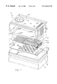
- FIG. 7 is an exploded perspective view of the ink jet nozzle of FIG. 1 .
- FIG. 8 is a perspective view of a section of an ink jet printhead incorporating a plurality of the ink jet nozzles of FIG. 1 .
- the ink jet nozzle from which ink is ejected is actuated by means of a thermal actuator which includes a “corrugated” copper heating element encased in a polytetrafluoroethylene (PTFE) layer.
- PTFE polytetrafluoroethylene
- the ink jet nozzle 10 includes an ink ejection port 11 for the ejection of ink from a chamber 12 by means of actuation of a thermal paddle actuator 13 .
- the thermal paddle actuator 13 comprises an inner copper heating portion 14 and paddle 15 which are encased in a PTFE layer 16 .
- the PTFE layer 16 has an extremely high coefficient of thermal expansion (approximately 770 ⁇ 10 ⁇ 6, or around 380 times that of silicon).
- the PTFE layer 16 is also highly hydrophobic which results in an air bubble 17 being formed under the actuator 13 due to out-gassing etc.
- a top surface of the PTFE layer 16 is treated so as to make it hydrophilic.
- the heating portion 14 is also formed within a lower portion of the actuator 13 .
- the heating portion 14 is connected at ends 20 , 21 (see also FIG. 7) to a lower CMOS drive layer 18 containing drive circuitry (not shown).
- a current is passed through the heating portion 14 which heats the lower portion of the actuator 13 .
- FIG. 2 a bottom surface of the actuator 13 , in contact with an air bubble 17 remains heated while any top surface heating is carried away by the exposure of the top surface of the actuator 13 to the ink within the chamber 12 .
- the lower portion of the PTFE layer expands more rapidly resulting in a general bending upwards of the actuator 13 (as illustrated in FIG. 2) which consequentially causes the ejection of ink from the ink ejection port 11 .
- An air inlet channel 28 is formed between a nitride layer 42 , and a PTFE layer 26 such that air is free to flow in the direction of an arrow 29 along a channel 28 and through holes 25 , to accommodate any fluctuating pressure influences plurality of posts 27 are positioned between the layers 42 , 26 .
- air introduced into the ink jet nozzle 10 is in fluid communication with the air bubble 17 .
- the air flow acts to reduce a vacuum acting on the bottom surface of the actuator 13 during operation. As a result, less energy is required for the movement of the actuator 13 .
- the actuator 13 can be deactivated by turning off the current to the heating portion 14 . This results in a return of the actuator 13 to its rest position.
- the actuator 13 includes a number of significant features.
- FIG. 3 there is illustrated a schematic diagram of the conductive layer of the thermal actuator 13 .
- the conductive layer includes the panel 15 , which can be constructed from the same material as the heating portion as 14 , i.e. copper, and which contains a series of holes 23 .
- the holes 23 are provided for interconnecting PTFE both above and below the panel 15 so as to resist any movement of the PTFE layers past the panel 15 and thereby reduce any opportunities for the delamination of the PTFE and the copper.
- FIG. 4 there is illustrated a close up view of a portion of the actuator 13 of FIG. 1 illustrating corrugations 22 of the heating portion 14 .
- the corrugations 22 of the heater 14 allow for a rapid heating of the lower portion. Any resistive heater which is based upon applying a current to heat an object will result in a rapid, substantially uniform elevation in temperature of the outer surface of the current carrying conductor.
- the surrounding PTFE is therefore heated by means of thermal conduction from the resistive element. This thermal conduction is known to proceed, to a first approximation, at a substantially linear rate with respect to distance from a resistive element.
- the lower portion of the actuator 13 is more rapidly heated. Therefore, the utilization of a corrugated resistive element results in a more rapid heating of the lower portion and therefore a rapid actuation of the actuator 13 .
- the corrugations 22 also assist in resisting any delamination of the copper and PTFE.
- the corrugations 22 can be formed by depositing a resist layer 50 on top of the first PTFE layer 51 .
- the resist layer 50 is exposed utilizing a mask 52 having a half-tone pattern delineating the corrugations. After development, the resist layer 50 contains the corrugation pattern.
- the resist layer 50 and the PTFE layer 51 are then etched utilizing an etchant that erodes the resist layer 50 at substantially the same rate as the PTFE layer 51 . This transfers the corrugated pattern into the PTFE layer 51 .
- FIG. 6 on top of the corrugated PTFE layer 51 is deposited the heating portion 14 which takes on a corrugated form in accordance with its under layer.
- the copper heating portion 14 is then etched in a serpentine or concertina form. Subsequently, a second PTFE layer 53 is deposited on top of the heating portion 14 so as to form a top layer of the thermal actuator 13 . Finally, the second PTFE layer 52 is planarized to form the top surface of the thermal actuator 13 (FIG. 1 ).
- ink can be supplied via a channel 38 which can be constructed by means of deep anisotropic silicon trench etching such as that available from STS Limited (“Advanced Silicon Etching Using High Density Plasmas” by J. K. Bhardwaj, H. Ashraf, page 224 of Volume 2639 of the SPIE Proceedings in Micro Machining and Micro Fabrication Process Technology).
- the ink supply flows from the channel 38 through side grill portions 40 (see also FIG. 7) into the chamber 12 .
- the grill portions 40 which can comprise silicon nitride or similar insulating material act to remove foreign bodies from the ink flow.
- the grill 40 also helps to pinch the PTFE actuator 13 to a base CMOS layer 18 , the pinching providing an important assistance for the thermal actuator 13 so as to ensure a substantially decreased likelihood of the thermal actuator layer 13 separating from a base CMOS layer 18 .
- a series of sacrificial etchant holes 19 are provided in a top wall 48 of the chamber 12 to allow sacrificial etchant to enter the chamber 12 during fabrication so as to increase the rate of etching.
- the small size of the holes 19 does not affect the operation of the device 10 substantially as the surface tension across the holes 19 , stops ink from being ejected from these holes, whereas, the larger size port 11 allows for the ejection of ink.
- FIG. 7 there is illustrated an exploded perspective view of a single nozzle 10 .
- the nozzle 10 can be formed in layers starting with a silicon wafer device 41 having a CMOS layer 18 on top thereof as required.
- the CMOS layer 18 provides the various drive circuitry for driving the copper heating portion 14 .
- a nitride layer 42 is deposited, providing protection for lower layers from corrosion or etching.
- a PTFE layer 26 is constructed having the aforementioned holes 25 , and posts 27 .
- the structure of the PTFE layer 26 can be formed by first laying down a sacrificial glass layer (not shown) onto which the PTFE layer 26 is deposited.
- the PTFE layer 26 includes various features, for example, a lower ridge portion 30 in addition to vias for subsequent material layers.
- the process of creating a first PTFE layer proceeds by laying down a sacrificial layer on top of layer 26 in which the air bubble underneath actuator 13 (FIG. 1) subsequently forms. On top of this is formed a first PTFE layer utilizing the relevant mask.
- the PTFE layer includes vias for the subsequent copper interconnections.
- a copper layer 43 is deposited on top of the first PTFE layer and a second PTFE layer is deposited on top of the copper layer 43 , in each case, utilizing the required mask.
- the nitride layer 46 can be formed by the utilization of a sacrificial glass layer which is masked and etched as required to form the side walls and the grill 40 . Subsequently, the top nitride layer 48 is deposited again utilizing the appropriate mask having the holes 19 as required. Subsequently, the various sacrificial layers can be etched away so as to release the structure of the thermal actuator 13 .
- FIG. 8 there is illustrated a section of an ink jet printhead configuration 90 utilizing ink jet nozzles constructed in accordance with the preferred embodiment, e.g. 91 .
- the configuration 90 can be utilized in a three color process 1600 dpi print-head utilizing 3 sets of 2 rows of nozzle chambers 92 , 93 , which are interconnected to one ink supply channel, e.g. 94 , for each set.
- the 3 supply channels 94 , 95 , 96 are interconnected to cyan coloured, magenta coloured and yellow coloured ink reservoirs respectively.
- the embodiments of the invention use an ink jet printer type device. Of course many different devices could be used. However presently popular ink jet printing technologies are unlikely to be suitable.
- thermal ink jet The most significant problem with thermal ink jet is power consumption. This is approximately 100 times that required for high speed, and stems from the energy-inefficient means of drop ejection. This involves the rapid boiling of water to produce a vapor bubble which expels the ink. Water has a very high heat capacity, and must be superheated in thermal ink jet applications. This leads to an efficiency of around 0.02%, from electricity input to drop momentum (and increased surface area) out.
- piezoelectric ink jet The most significant problem with piezoelectric ink jet is size and cost. Piezoelectric crystals have a very small deflection at reasonable drive voltages, and therefore require a large area for each nozzle. Also, each piezoelectric actuator must be connected to its drive circuit on a separate substrate. This is not a significant problem at the current limit of around 300 nozzles per printhead, but is a major impediment to the fabrication of pagewidth printheads with 19,200 nozzles.
- the ink jet technologies used meet the stringent requirements of in-camera digital color printing and other high quality, high speed, low cost printing applications.
- new ink jet technologies have been created.
- the target features include:
- ink jet designs shown here are suitable for a wide range of digital printing systems, from battery powered one-time use digital cameras, through to desktop and network printers, and through to commercial printing systems.
- the printhead is designed to be a monolithic 0.5 micron CMOS chip with MEMS post processing.
- the printhead is 100 mm long, with a width which depends upon the ink jet type.
- the smallest printhead designed is IJ38, which is 0.35 mm wide, giving a chip area of 35 square mm.
- the printheads each contain 19,200 nozzles plus data and control circuitry.
- Ink is supplied to the back of the printhead by injection molded plastic ink channels.
- the molding requires 50 micron features, which can be created using a lithographically micromachined insert in a standard injection molding tool.
- Ink flows through holes etched through the wafer to the nozzle chambers fabricated on the front surface of the wafer.
- the printhead is connected to the camera circuitry by tape automated bonding.
- ink jet configurations can readily be derived from these forty-five examples by substituting alternative configurations along one or more of the 11 axes.
- Most of the IJ01 to IJ45 examples can be made into ink jet printheads with characteristics superior to any currently available ink jet technology.
- Suitable applications for the ink jet technologies include: Home printers, Office network printers, Short run digital printers, Commercial print systems, Fabric printers, Pocket printers, Internet WWW printers, Video printers, Medical imaging, Wide format printers, Notebook PC printers, Fax machines, Industrial printing systems, Photocopiers, Photographic minilabs etc.
- Perovskite materials such strain Actuators require a large area as tin modified lead lanthanum High efficiency zirconate titanate (PLZSnT) Electric field strength of around exhibit large strains of up to 1% 3 V/ ⁇ m can be readily provided associated with the AFE to FE phase transition.
- Electrostatic Conductive plates are separated Low power consumption Difficult to operate electrostatic IJ02, IJ04 plates by a compressible or fluid Many ink types can be used devices in an aqueous environ- dielectric (usually air). Upon Fast operation ment application of a voltage, the The electrostatic actuator will plates attract each other and normally need to be separated displace ink, causing drop from the ink ejection.
- the conductive plates Very large area required to may be in a comb or honeycomb achieve high forces structure, or stacked to increase High voltage drive transistors the surface area and therefore may be required the force.
- Full pagewidth print heads are not competitive due to actuator size
- Electrostatic A strong electric field is applied Low current consumption High voltage required 1989 Saito et al, U.S. Pat. No. pull on ink to the ink, whereupon electro- Low temperature May be damaged by sparks due 4,799,068 static attraction accelerates the to air breakdown 1989 Miura et al, U.S. Pat. No. ink towards the print medium.
- Examples nozzles to pagewidth print Copper metalization should be are: Samarium Cobalt (SaCo) heads used for long electromigration and magnetic materials in the lifetime and low resistivity neodymium iron boron family Pigmented inks are usually (NdFeB, NdDyFeBNb, infeasible NdDyFeB, etc) Operating temperature limited to the Curie temperature (around 540 K.) Soft magnetic A solenoid induced a magnetic Low power consumption Complex fabrication IJ01, IJ05, IJ08, IJ10, IJ12, IJ14, core electro- field in a soft magnetic core or Many ink types can be used Materials not usually present in IJ15, IJ17 magnetic yoke fabricated from a ferrous Fast operation a CMOS fab such as NiFe, material such as electroplated High efficiency CoNiFe, or CoFe are required iron alloys such as CoNiFe [1], Easy extension from single High local currents required CoFe, or NiF
- nozzles to pagewidth print Copper metalization should be the soft magnetic material is in heads used for long electromigration two parts, which are normally lifetime and low resistivity held apart by a spring.
- the Electroplating solenoid is actuated, the two High saturation flux density is parts attract, displacing the ink. required (2.0-2.1 T is achievable with CoNiFe [1])
- Lorenz force The Lorenz force acting on a Low power consumption Force acts as a twisting motion IJ06, IJ11, IJ13, IJ16 current carrying wire in a Many ink types can be used Typically, only a quarter of the magnetic field is utilized.
- This Fast operation solenoid length provides force allows the magnetic field to be High efficiency in a useful direction supplied externally to the print Easy extension from single High local currents required head, for example with rare nozzles to pagewidth print Copper metalization should be earth permanent magnets. Only heads used for long electromigration the current carrying wire need be lifetime and low resistivity fabricated on the print-head, Pigmented inks are usually simplifying materials require- infeasible ments. Magneto- The actuator uses the giant Many ink types can be used Force acts as a twisting motion Fischenbeck, U.S. Pat. No.
- a viscosity fabrication Requires special ink viscosity reduction can be achieved Easy extension from single surfactants electrothermally with most inks, nozzles to pagewidth print High speed is difficult to but special inks can be heads achieve engineered for a 100:1 viscosity Requires oscillating ink pressure reduction.
- a high temperature difference typically 80 degrees
- Acoustic An acoustic wave is generated Can operate without a nozzle Complex drive circuitry 1993 Hadimioglu et al, EUP and focussed upon the drop plate Complex fabrication 550,192 ejection region.
- Pigmented inks may be High efficiency infeasible, as pigment particles CMOS compatible voltages and may jam the bend actuator currents
- Standard MEMS processes can be used Easy extension from single nozzles to pagewidth print heads High CTE A material with a very high High force can be generated Requires special material (e.g.
- IJ23, IJ24, IJ27, IJ28, IJ29, IJ30, actuator (CTE) such as polytetrafluoro- tion are under development: Requires a PTFE deposition IJ31, IJ42, IJ43, IJ44 ethylene (PTFE) is used.
- Pigmented inks may be 15 mW power input can provide Many ink types can be used infeasible, as pigment particles 180 ⁇ N force and 10 ⁇ m Simple planar fabrication may jam the bend actuator deflection.
- Actuator motions Small chip area required for include: actuator Bend Fast operation Push High efficiency Buckle CMOS compatible voltages and Rotate currents Easy extension from single nozzles to pagewidth print heads Conductive A polymer with a high co- High force can be generated Requires special materials IJ24 polymer efficient of thermal expansion Very low power consumption development (High CTE con- thermoelastic (such as PTFE) is doped with Many ink types can be used ductive polymer) conducting substances to Simple planar fabrication Requires a PTFE deposition increase its conductivity to about Small chip area required for process, which is not yet 3 orders of magnitude below that actuator standard in ULSI fabs of copper.
- CMOS compatible voltages and ature (above 350° C.) conducting dopants include: currents processing Carbon nanotubes Easy extension from single Evaporation and CVD deposi- Metal fibers nozzles to pagewidth print tion techniques cannot be used Conductive polymers such as heads Pigmented inks may be in- doped polythiophene feasible, as pigment particles Carbon granules may jam the bend actuator Shape memory
- a shape memory alloy such as High force is available Fatigue limits maximum number IJ26 alloy TiNi (also known as Nitinol - (stresses of hundreds of of cycles Nickel Titanium alloy developed MPa) Low strain (1%) is required to at the Naval Ordnance Labora- Large strain is available extend fatigue resistance tory) is thermally switched (more than 3%) Cycle rate limited by heat between its weak martensitic High corrosion resistance removal state and its high stiffness Simple construction Requires unusual materials austenic state.
- the shape of the Easy extension from single (TiNi) actuator in its martensitic state is nozzles to pagewidth print
- the latent heat of trans- deformed relative to the austenic heads formation must be provided shape.
- the shape change causes Low voltage operation High current operation ejection of a drop.
- Linear Linear magnetic actuators can Requires unusual semiconductor IJ12 Magnetic include the Linear Induction be constructed with high thrust, materials such as soft magnetic Actuator Actuator (LIA), Linear long travel, and high efficiency alloys (e.g.
- Satellite drops can be avoided if ever, this is not fundamental IJ01, IJ02, IJ03, IJ04, IJ05, IJ06, to expel the drop.
- the drop must drop velocity is less than 4 m/s to the method, but is related IJ07, IJ09, IJ11, IJ12, IJ14, IJ16, have a sufficient velocity to Can be efficient, depending to the refill method normally IJ20, IJ22, IJ23, IJ24, IJ25, IJ26, overcome the surface tension.
- the drop selection means does print media or transfer roller tension reduction of pressurized not need to provide the energy May require two print heads ink). Selected drops are required to separate the drop printing alternate rows of the separated from the ink in the from the nozzle image nozzle by contact with the print Monolithic color print heads are medium or a transfer roller. difficult Electrostatic The drops to be printed are Very simple print head fabri- Requires very high electrostatic Silverbrook, EP 0771 658 A2 pull on ink selected by some manner (e.g.
- the drop selection means does Electrostatic field for small Tone-Jet tension reduction of pressurized not need to provide the energy nozzle sizes is above air break- ink). Selected drops are required to separate the drop down separated from the ink in the from the nozzle Electrostatic field may attract nozzle by a strong electric field. Dust Magnetic
- the drops to be printed are Very simple print head fabrica- Requires magnetic ink Silverbrook, EP 0771 658 A2 pull on ink selected by some manner (e.g. tion can be used Ink colors other than black are and related patent applications thermally induced surface
- the drop selection means does difficult tension reduction of pressurized not need to provide the energy Requires very high magnetic ink).
- Selected drops are required to separate the drop fields separated from the ink in the from the nozzle nozzle by a strong magnetic field acting on the magnetic ink.
- Shutter The actuator moves a shutter to High speed (>50 kHz) operation Moving parts are required IJ13, IJ17, IJ21 block ink flow the nozzle. The can be achieved due to reduced Requires ink pressure modulator ink pressure is pulsed at a refill time Friction and wear must be con- multiple of the drop ejection Drop timing can be very sidered frequency.
- the actuator energy can be very low Shuttered
- the actuator moves a shutter to Actuators with small travel can Moving parts are required IJ08, IJ15, IJ18, IJ19 grill block ink flow through a grill to be used Requires ink pressure modulator the nozzle.
- the shutter move- Actuators with small force can Friction and wear must be con- ment need only be equal to the be used sidered width of the grill holes.
- High speed (>50 kHz) operation Stiction is possible can be achieved Pulsed mag- A pulsed magnetic field attracts Extremely low energy operation Requires an external pulsed IJ10 netic pull on an ‘ink pusher’ at the drop is possible magnetic field ink pusher ejection frequency.
- the actuator selects higher operating speed Ink pressure phase and IJ08, IJ13, IJ15, IJ17, IJ18, IJ19, acoustic which drops are to be fired by
- the actuators may operate with amplitude must be carefully IJ21 stimulation) selectively blocking or enabling much lower energy controlled nozzles.
- the ink pressure Acoustic lenses can be used to Acoustic reflections in the ink oscillation may be achieved by focus the sound on the nozzles chamber must be designed for vibrating the print head, or preferably by an actuator in the ink supply.
- Media The print head is placed in close Low power Precision assembly required Silverbrook, EP 0771 658 A2 proximity proximity to the print medium.
- High accuracy Paper fibers may cause problems and related patent applications Selected drops protrude from the Simple print head construction Cannot print on rough substrates print head further than unselected drops, and contact the print medium. The drop soaks into the medium fast enough to cause drop separation.
- Transfer roller Drops are printed to a transfer High accuracy Bulky Silverbrook, EP 0771 658 A2 roller instead of straight to the Wide range of print substrates Expensive and related patent applications print medium.
- a transfer roller can be used Complex construction Tektronix hot melt piezoelectric can also be used for proximity Ink can be dried on the transfer ink jet drop separation.
- the materials to be integrated in the Current densities may be high, Lorenz force in a current carry- print head manufacturing resulting in electromigration ing wire is used to move the process problems actuator.
- Pulsed mag- A pulsed magnetic field is used Very low power operation is Complex print head construction IJ10 netic field to cyclically attract a paddle, possible Magnetic materials required in which pushes on the ink.
- a Small print head size print head small actuator moves a catch, which selectively prevents the paddle from moving.
- drop ejection process Differential An actuator material expands Provides greater travel in a High stresses are involved Piezoelectric expansion more on one side than on the reduced print head area Care must be taken that the IJ03, IJ09, IJ17, IJ18, IJ19, IJ20, bend actuator other.
- the expansion may be materials do not delaminate IJ21, IJ22, IJ23, IJ24, IJ27, IJ29, thermal, piezoelectric, magneto- Residual bend resulting from IJ30, IJ31, IJ32, IJ33, IJ34, IJ35, strictive, or other mechanism.
- high temperature or high stress IJ36, IJ37, IJ38, IJ39, IJ42, IJ43
- the bend actuator converts a during formation IJ44 high force low travel actuator mechanism to high travel, lower force mechanism.
- Transient bend A trilayer bend actuator where Very good temperature stability High stresses are involved IJ40, IJ41 actuator the two outside layers are High speed, as a new drop can Care must be taken that the identical.
- actuators require high circuits due to pinholes electric field strength, such as electrostatic and piezoelectric actuators.
- Multiple Multiple smaller actuators are Increases the force available Actuator forces may not added IJ12, IJ13, IJ18, IJ20, IJ22, IJ28, actuators used simultaneously to move the from an actuator linearly, reducing efficiency IJ42, IJ43 ink.
- Each actuator need provide Multiple actuators can be only a portion of the force positioned to control ink flow accurately required.
- Linear Spring A linear spring is used to Matches low travel actuator with Requires print head area for the IJ15 transform a motion with small higher travel requirements spring travel and high force into a Non-contact method of motion longer travel, lower force transformation motion.
- Coiled actuator A bend actuator is coiled to Increased travel Generally restricted to planar IJ17, IJ21, IJ34, IJ35 provide greater travel in a Reduced chip area implementations due to extreme reduced chip area. Planar implementations are fabrication difficulty in other relatively easy to fabricate. orientations.
- Flexure bend A bend actuator has a small Simple means of increasing Care must be taken not to IJ10, IJ19, IJ33 actuator region near the fixture point, travel of a bend actuator exceed the elastic limit in the which flexes much more readily flexure area than the remainder of the Stress distribution is very actuator.
- the actuator flexing is uneven effectively converted from an Difficult to accurately model even coiling to an angular bend, with finite element analysis resulting in greater travel of the actuator tip.
- Catch The actuator controls a small Very low actuator energy Complex construction IJ10 catch. The catch either enables Very small actuator size Requires external force or disables movement of an ink Unsuitable for pigmented inks pusher that is controlled in a bulk manner.
- Gears Gears can be used to increase Low force, low travel actuators Moving parts are required IJ13 travel at the expense of duration. can be used Several actuator cycles are Circular gears, rack and pinion, Can be fabricated using standard required ratchets, and other gearing surface MEMS processes More complex drive electronics methods can be used. Complex construction Friction, friction, and wear are possible Buckle plate A buckle plate can be used to Very fast movement achievable Must stay within elastic limits of S. Hirata et al, “An Ink-jet Head change a slow actuator into a the materials for long device life Using Diaphragm Micro- fast motion. It can also convert High stresses involved actuator”, Proc. IEEE MEMS, a high force, low travel actuator Generally high power require- Feb. 1996, pp 418-423.
- Acoustic lens A refractive or diffractive e.g. A moving parts Large area required 1993 Hadimioglu et al, EUP zone plate
- acoustic lens is used Only relevant for acoustic ink 550,192 to concentrate sound waves.
- jets 1993 Elrod et al, EUP 572,220 Sharp conduc- A sharp point is used to con- Simple construction Difficult to fabricate using Tone-jet tive point centrate an electrostatic field.
- the nozzle is pendicular motion typically in the line of movement. Parallel to The actuator moves parallel to Suitable for planar fabrication Fabrication complexity IJ12, IJ13, IJ15, IJ33, IJ34, IJ35, chip surface the print head surface. Drop Friction IJ36 ejection may still be normal to Stiction the surface.
- Membrane An actuator with a high force The effective area of the actuator Fabrication complexity 1982 Howkins U.S. Pat. No. push but small area is used to push a becomes the membrane area Actuator size 4,459,601 stiff membrane that is in contact Difficulty of integration in a with the ink.
- the actuator causes the rotation Rotary levers may be used to Device complexity IJ05, IJ08, IJ13, IJ28 of some element, such a grill or increase travel May have friction at a pivot impeller Small chip area requirements point Bend
- the actuator bends when A very small change in Requires the actuator to be made 1970 Kyser et al U.S. Pat. No. energized. This may be due to dimensions can be converted to from at least two distinct layers, 3,946,398 differential thermal expansion, a large motion. or to have a thermal difference 1973 Stemme U.S. Pat. No.
- the actuator bends in one One actuator can be used to Difficult to make the drops IJ36, IJ37, IJ38 direction when one element is power two nozzles. ejected by both bend directions energized, and bends the other Reduced chip size. identical. way when another element is Not sensitive to ambient A small efficiency loss energized. temperature compared to equivalent single bend actuators. Shear Energizing the actuator causes a Can increase the effective travel Not readily applicable to other 1985 Fishbeck U.S. Pat. No. shear motion in the actuator of piezoelectric actuators actuator mechanisms 4,584,590 material.
- the actuator squeezes an ink Relatively easy to fabricate High force required 1970 Zoltan U.S. Pat. No. striction reservoir, forcing ink from a single nozzles from glass tubing Inefficient 3,683,212 constricted nozzle. as macroscopic structures Difficult to integrate with VLSI processes Coil/uncoil A coiled actuator uncoils or coils Easy to fabricate as a planar Difficult to fabricate for non- IJ17, IJ21, IJ34, IJ35 more tightly. The motion of the VLSI process planar devices free end of the actuator ejects Small area required, therefore Poor out-of-plane stiffness the ink.
- Shuttered Ink to the nozzle chamber is High speed Requires common ink pressure IJ08, IJ13, IJ15, IJ17, IJ18, IJ19, oscillating provided at a pressure that Low actuator energy, as the oscillator IJ21 ink pressure oscillates at twice the drop actuator need only open or close May not be suitable for ejection frequency.
- the shutter instead of ejecting pigmented inks is to be ejected, the shutter is the ink drop opened for 3 half cycles: drop ejection, actuator return, and refill. The shutter is then closed to prevent the nozzle chamber emptying during the next negative pressure cycle.
- Refill actuator After the main actuator has High speed, as the nozzle is Requires two independent IJ09 ejected a drop a second (refill) actively refilled actuators per nozzle actuator is energized.
- the refill actuator pushes ink into the nozzle chamber.
- the refill actuator returns slowly, to prevent its return from emptying the chamber again. Positive ink
- the ink is held a slight positive High refill rate, therefore a high Surface spill must be prevented Silverbrook, EP 0771 658 A2 pressure pressure.
- the nozzle chamber fills surfaces are required Alternate for: IJ01-IJ07, IJ10- quickly as surface tension and IJ14, IJ16, IJ20, IJ22-IJ45 ink pressure both operate to refill the nozzle.
- the ink inlet channel to the Design simplicity Restricts refill rate Thermal ink jet channel nozzle chamber is made long Operational simplicity May result in a relatively large Piezoelectric ink jet and relatively narrow, relying on Reduces crosstalk chip area IJ42, IJ43 viscous drag to reduce inlet Only partially effective back-flow Positive ink
- the ink is under a positive Drop selection and separation Requires a method (such as a Silverbrook, EP 0771 658 A2 pressure pressure, so that in the quiescent forces can be reduced nozzle rim or effective hydro- and related patent applications state some of the ink drop Fast refill time phobizing, or both) to prevent Possible operation of the already protrudes from the flooding of the ejection surface following: IJ01-IJ07, IJ09-IJ12, nozzle.
- the filter has a Ink filter may be fabricated with construction multitude of small holes or slots, no additional process steps restricting ink flow.
- the filter also removes particles which may block the nozzle.
- Small inlet The ink inlet channel to the Design simplicity Restricts refill rate IJ02, IJ37, IJ44 compared to nozzle chamber has a sub- May result in a relatively large nozzle stantially smaller cross section chip area than that of the nozzle, resulting Only partially effective in easier ink egress out of the nozzle than out of the inlet.
- Inlet shutter A secondary actuator controls Increases speed of the ink-jet Requires separate refill actuator IJ09 the position of a shutter, closing print head operation and drive circuit off the ink inlet when the main actuator is energized.
- the inlet is The method avoids the problem Back-flow problem is eliminated Requires careful design to IJ01, IJ03, IJ05, IJ06, IJ07, IJ10, located behind of inlet back-flow by arranging minimize the negative pressure IJ11, IJ14, IJ16, IJ22, IJ23, IJ25, the ink-pushing the ink-pushing surface of the behind the paddle IJ28, IJ31, IJ32, IJ33, IJ34, IJ35, surface actuator between the inlet and IJ36, IJ39, IJ40, IJ41 the nozzle.
- NOZZLE CLEARING METHOD Normal nozzle All of the nozzles are fired No added complexity on the May not be sufficient to displace Most ink jet systems firing periodically, before the ink has a print head dried ink IJ01, IJ02, IJ03, IJ04, IJ05, IJ06, chance to dry.
- IJ07, IJ09, IJ10, IJ11, IJ12, IJ14 the nozzles are sealed (capped) IJ16, IJ20, IJ22, IJ23, IJ24, IJ25, against air.
- the nozzle firing is IJ26, IJ27, IJ28, IJ29, IJ30, IJ31, usually performed during a IJ32, IJ33, IJ34, IJ36, IJ37, IJ38, special clearing cycle, after first IJ39, IJ40, IJ41, IJ42, IJ43, IJ44, moving the print head to a IJ45 cleaning station.
- Extra power In systems which heat the ink, Can be highly effective if the Requires higher drive voltage Silverbrook, EP 0771 658 A2 to ink heater but do not boil it under normal heater is adjacent to the nozzle for clearing and related patent applications situations, nozzle clearing can be May require larger drive achieved by over-powering the transistors heater and boiling ink at the nozzle.
- Rapid success- The actuator is fired in rapid Does not require extra drive Effectiveness depends sub- May be used with: IJ01, IJ02, ion of actuator succession.
- IJ01, IJ02, ion of actuator succession In some configura- circuits on the print head stantially upon the configuration IJ03, IJ04, IJ05, IJ06, IJ07, IJ09, pulses tions, this may cause heat build- Can be readily controlled and of the ink jet nozzle IJ10, IJ11, IJ14, IJ16, IJ20, IJ22, up at the nozzle which boils the initiated by digital logic IJ23, IJ24, IJ25, IJ27, IJ28, IJ29, ink, clearing the nozzle.
- IJ30 In other IJ30, IJ31, IJ32, IJ33, IJ34, IJ36, situations, it may cause IJ37, IJ38, IJ39, IJ40, IJ41, IJ42, sufficient vibrations to dislodge IJ43, IJ44, IJ45 clogged nozzles.
- This wave is of can be achieved system does not already include IJ21 an appropriate amplitude and May be implemented at very low an acoustic actuator frequency to cause sufficient cost in systems which already force at the nozzle to clear include acoustic actuators blockages. This is easiest to achieve if the ultrasonic wave is at a resonant frequency of the ink cavity.
- Nozzle clearing A microfabricated plate is Can clear severely clogged Silverbrook, EP 0771 658 A2 plate pushed against the nozzles.
- the nozzles and related patent applications plate has a post for every nozzle. Moving parts are required A post moves through each There is risk of damage to the nozzle, displacing dried ink.
- Ink pressure The pressure of the ink is May be effective where other Requires pressure pump or other May be used with all IJ series pulse temporarily increased so that methods cannot be used pressure actuator ink jets ink streams from all of the Expensive nozzles. This may be used in Wasteful of ink conjunction with actuator energizing.
- Print head A flexible ‘blade’ is wiped Effective for planar print head Difficult to use if print head Many ink jet systems wiper across the print head surface. surfaces surface is non-planar or very The blade is usually fabricated Low cost fragile from a flexible polymer, e.g. Requires mechanical parts rubber or synthetic elastomer.
- Blade can wear out in high volume print systems
- Separate ink A separate heater is provided at Can be effective where other Fabrication complexity Can be used with many IJ series boiling heater the nozzle although the normal nozzle clearing methods cannot ink jets drop e-ection mechanism does be used not require it.
- the heaters do not Can be implemented at no require individual drive circuits, additional cost in some ink jet as many nozzles can be cleared configurations simultaneously, and no imaging is required.
- NOZZLE PLATE CONSTRUCTION Electroformed A nozzle plate is separately Fabrication simplicity High temperatures and pressures Hewlett Packard Thermal Ink jet nickel fabricated from electroformed are required to bond nozzle plate nickel, and bonded to the print Minimum thickness constraints head chip.
- Nozzles may be clogged by 1195 adhesive Xerox 1990 Hawkins et al., U.S. Pat. No. 4,899,181 Glass Fine glass capillaries are drawn No expensive equipment Very small nozzle sizes are 1970 Zoltan U.S. Pat. No. capillaries from glass tubing. This method required difficult to form 3,683,212 has been used for making Simple to make single nozzles Not suited for mass production individual nozzles, but is difficult to use for bulk manufacturing of print heads with thousands of nozzles.
- the nozzle plate is deposited High accuracy ( ⁇ 1 ⁇ m) Requires sacrificial layer under Silverbrook, EP 0771 658 A2 surface micro- as a layer using standard VLSI Monolithic the nozzle plate to form the and related patent applications machined using deposition techniques.
- Nozzles Low cost nozzle plate to form the IJ01, IJ02, IJ04, IJ11, IJ12, IJ17, VLSI litho- are etched in the nozzle plate
- Existing processes can be used nozzle chamber IJ18, IJ20, IJ22, IJ24, IJ27, IJ28, graphic pro- using VLSI lithography and Surface may be fragile to the IJ29, IJ30, IJ31, IJ32, IJ33, IJ34, Determination.
- the nozzle plate is a buried High accuracy ( ⁇ 1 ⁇ m) Requires long etch times IJ03, IJ05, IJ06, IJ07, IJ08, IJ09, etched through etch stop in the wafer.
- Nozzle Monolithic Requires a support wafer IJ10, IJ13, IJ14, IJ15, IJ16, IJ19, substrate chambers are etched in the Low cost IJ21, IJ23, IJ25, IJ26 front of the wafer, and the No differential expansion wafer is thinned from the back side.
- Nozzles are then etched in the etch stop layer.
- No nozzle plate Various methods have been tried No nozzles to become clogged Difficult to control drop position Ricoh 1995 Sekiya et al U.S. to eliminate the nozzles entirely, accurately Pat. No. 5,412,413 to prevent nozzle clogging.
- Crosstalk problems 1993 Hadimioglu et al EUP These include thermal bubble 550,192 mechanisms and acoustic lens 1993 Elrod et al EUP 572,220 mechanisms Trough Each drop ejector has a trough Reduced manufacturing Drop firing direction is IJ35 through which a paddle moves. complexity sensitive to wicking. There is no nozzle plate.
- Suitable for piezoelectric print Pagewidth print heads require Epson Stylus which is not fabricated as part of heads several thousand connections to Tektronix hot melt piezoelectric the same substrate as the drive drive circuits ink jets transistors. Cannot be manufactured in standard CMOS fabs Complex assembly required INK TYPE Aqueous, dye Water based ink which typically Environmentally friendly Slow drying Most existing ink jets contains: water, dye, surfactant, No odor Corrosive All IJ series ink jets humectant, and biocide.
- Methyl Ethyl MEK is a highly volatile solvent Very fast drying Odorous All IJ series ink jets Ketone (MEK) used for industrial printing on Prints on various substrates Flammable difficult surfaces such as such as metals and plastics aluminum cans. Alcohol Alcohol based inks can be used Fast drying Slight odor All IJ series ink jets (ethanol, 2- where the printer must operate Operates at sub-freezing temper- Flammable butanol, and at temperatures below the atures others) freezing point of water. An Reduced paper cockle example of this is in-camera Low cost consumer photographic printing.
- Phase change The ink is solid at room temper- No drying time-ink instantly High viscosity Tektronix hot melt piezoelectric (hot melt) ature, and is melted in the print freezes on the print medium
- Printed ink typically has a ink jets head before jetting. Hot melt Almost any print medium can be ‘waxy’ feel 1989 Nowak U.S. Pat. No. inks are usually wax based, with used Printed pages may ‘block’ 4,820,346 a melting point around 80° C..
- Oil soluble dies and sufficiently low viscosity. pigments are required.
- Slow drying Microemulsion A microemulsion is a stable, Stops ink bleed Viscosity higher than water All IJ series ink jets self forming emulsion of oil, High dye solubility Cost is slightly higher than water water, and surfactant.
- the Water, oil, and amphiphilic based ink characteristic drop size is less soluble dies can be used High surfactant concentration than 100 nm, and is determined Can stabilize pigment required (around 5%) by the preferred curvature of the suspensions surfactant.
Abstract
Description
| CROSS-REFERENCED | U.S. PATENT/ | |
| AUSTRALIAN | PATENT APPLICATION | |
| PROVISIONAL | (CLAIMING RIGHT OF | |
| PATENT | PRIORITY FROM AUSTRALIAN | DOCKET |
| APPLICATION NO. | PROVISIONAL APPLICATION) | NO. |
| PO7991 | 09/113,060 | ART01 |
| PO8505 | 09/113,070 | ART02 |
| PO7988 | 09/113,073 | ART03 |
| PO9395 | 09/112,748 | ART04 |
| PO8017 | 09/112,747 | ART06 |
| PO8014 | 09/112,776 | ART07 |
| PO8025 | 09/112,750 | ART08 |
| PO8032 | 09/112,746 | ART09 |
| PO7999 | 09/112,743 | ART10 |
| PO7998 | 09/112,742 | ART11 |
| PO8031 | 09/112,741 | ART12 |
| PO8030 | 09/112,740 | ART13 |
| PO7997 | 09/112,739 | ART15 |
| PO7979 | 09/113,053 | ART16 |
| PO8015 | 09/112,738 | ART17 |
| PO7978 | 09/113,067 | ART18 |
| PO7982 | 09/113,063 | ART19 |
| PO7989 | 09/113,069 | ART20 |
| PO8019 | 09/112,744 | ART21 |
| PO7980 | 69/113,058 | ART22 |
| PO8018 | 09/112,777 | ART24 |
| PO7938 | 09/113,224 | ART25 |
| PO8016 | 09/112,804 | ART26 |
| PO8024 | 09/112,805 | ART27 |
| PO7940 | 09/113,072 | ART28 |
| PO7939 | 09/112,785 | ART29 |
| PO8501 | 09/112,797 | ART30 |
| PO8500 | 09/112,796 | ART31 |
| PO7987 | 09/113,071 | ART32 |
| PO8022 | 09/112,824 | ART33 |
| PO8497 | 09/113,090 | ART34 |
| PO8020 | 09/112,823 | ART38 |
| PO8023 | 09/113,222 | ART39 |
| PO8504 | 09/112,786 | ART42 |
| PO8000 | 09/113,051 | ART43 |
| PO7977 | 09/112,782 | ART44 |
| PO7934 | 09/113,056 | ART45 |
| PO7990 | 09/113,059 | ART46 |
| PO8499 | 09/113,091 | ART47 |
| PO8502 | 09/112,753 | ART48 |
| PO7981 | 09/113,055 | ART50 |
| PO7986 | 09/113,057 | ART51 |
| PO7983 | 09/113,054 | ART52 |
| PO8026 | 09/112,752 | ART53 |
| PO8027 | 09/112,759 | ART54 |
| PO8028 | 09/112,757 | ART56 |
| PO9394 | 09/112,758 | ART57 |
| PO9396 | 09/113,107 | ART58 |
| PO9397 | 09/112,829 | ART59 |
| PO9398 | 09/112,792 | ART60 |
| PO9399 | 6,106,147 | ART61 |
| PO9400 | 09/112,790 | ART62 |
| PO9401 | 09/112,789 | ART63 |
| PO9402 | 09/112,788 | ART64 |
| PO9403 | 09/112,795 | ART65 |
| PO9405 | 09/112,749 | ART66 |
| PP0959 | 09/112,784 | ART68 |
| PP1397 | 09/112,783 | ART69 |
| PP2370 | 09/112,781 | DOT01 |
| PP2371 | 09/113,052 | DOT02 |
| PO8003 | 09/112,834 | Fluid01 |
| PO8005 | 09/113,103 | Fluid02 |
| PO9404 | 09/113,101 | Fluid03 |
| PO8066 | 09/112,751 | IJ01 |
| PO8072 | 09/112,787 | IJ02 |
| PO8040 | 09/112,802 | IJ03 |
| PO8071 | 09/112,803 | IJ04 |
| PO8047 | 09/113,097 | IJ05 |
| PO8035 | 09/113,099 | IJ06 |
| PO8044 | 09/113,084 | IJ07 |
| PO8063 | 09/113,066 | IJ08 |
| PO8057 | 09/112,778 | IJ09 |
| PO8056 | 09/112,779 | IJ10 |
| PO8069 | 09/113,077 | IJ11 |
| PO8049 | 09/113,061 | IJ12 |
| PO8036 | 09/112,818 | IJ13 |
| PO8048 | 09/112,816 | IJ14 |
| PO8070 | 09/112,772 | IJ15 |
| PO8067 | 09/112,819 | IJ16 |
| PO8001 | 09/112,815 | IJ17 |
| PO8038 | 09/113,096 | IJ18 |
| PO8033 | 09/113,068 | IJ19 |
| PO8002 | 09/113,095 | IJ20 |
| PO8068 | 09/112,808 | IJ21 |
| PO8062 | 09/112,809 | IJ22 |
| PO8034 | 09/112,780 | IJ23 |
| PO8039 | 09/113,083 | IJ24 |
| PO8041 | 09/113,121 | IJ25 |
| PO8004 | 09/113,122 | IJ26 |
| PO8037 | 09/112,793 | IJ27 |
| PO8043 | 09/112,794 | IJ28 |
| PO8042 | 09/113,128 | IJ29 |
| PO8064 | 09/113,127 | IJ30 |
| PO9389 | 09/112,756 | IJ31 |
| PO9391 | 09/112,755 | IJ32 |
| PP0888 | 09/112,754 | IJ33 |
| PP0891 | 09/112,811 | IJ34 |
| PP0890 | 09/112,812 | IJ35 |
| PP0873 | 09/112,813 | IJ36 |
| PP0993 | 09/112,814 | IJ37 |
| PP0890 | 09/112,764 | IJ38 |
| PP1398 | 09/112,765 | IJ39 |
| PP2592 | 09/112,767 | IJ40 |
| PP2593 | 09/112,768 | IJ41 |
| PP3991 | 09/112,807 | IJ42 |
| PP3987 | 09/112,806 | IJ43 |
| PP3985 | 09/112,820 | IJ44 |
| PP3983 | 09/112,821 | IJ45 |
| PO7935 | 09/112,822 | IJM01 |
| PO7936 | 09/112,825 | IJM02 |
| PO7937 | 09/112,826 | IJM03 |
| PO8061 | 09/112,827 | IJM04 |
| PO8054 | 09/112,828 | IJM05 |
| PO8065 | 6,071,750 | IJM06 |
| PO8055 | 09/113,108 | IJM07 |
| PO8053 | 09/113,109 | IJM08 |
| PO8078 | 09/113,123 | IJM09 |
| PO7933 | 09/113,114 | IJM10 |
| PO7950 | 09/113,115 | IJM11 |
| PO7949 | 09/113,129 | IJM12 |
| PO8060 | 09/113,124 | IJM13 |
| PO8059 | 09/113,125 | IJM14 |
| PO8073 | 09/113,126 | IJM15 |
| PO8076 | 09/113,119 | IJM16 |
| PO8075 | 09/113,120 | IJM17 |
| PO8079 | 09/113,221 | IJM18 |
| PO8050 | 09/113,116 | IJM19 |
| PO8052 | 09/113,118 | IJM20 |
| PO7948 | 09/113,117 | IJM21 |
| PO7951 | 09/113,113 | IJM22 |
| PO8074 | 09/113,130 | IJM23 |
| PO7941 | 09/113,110 | IJM24 |
| PO8077 | 09/113,112 | IJM25 |
| PO8058 | 09/113,087 | IJM26 |
| PO8051 | 09/113,074 | IJM27 |
| PO8045 | 6,111,754 | IJM28 |
| PO7952 | 09/113,088 | IJM29 |
| PO8046 | 09/112,771 | IJM30 |
| PO9390 | 09/112,769 | IJM31 |
| PO9392 | 09/112,770 | IJM32 |
| PP0889 | 09/112,798 | IJM35 |
| PP0887 | 09/112,801 | IJM36 |
| PP0882 | 09/112,800 | IJM37 |
| PP0874 | 09/112,799 | IJM38 |
| PP1396 | 09/113,098 | IJM39 |
| PP3989 | 09/112,833 | IJM40 |
| PP2591 | 09/112,832 | 1JM41 |
| PP3990 | 09/112,831 | IJM42 |
| PP3986 | 09/112,830 | IJM43 |
| PP3984 | 09/112,836 | IJM44 |
| PP3982 | 09/112,835 | IJM45 |
| PP0895 | 09/113,102 | IR01 |
| PP0870 | 09/113,106 | IR02 |
| PP0869 | 09/113,105 | IR04 |
| PP0887 | 09/113,104 | IR05 |
| PP0885 | 09/112,810 | IR06 |
| PP0884 | 09/112,766 | IR10 |
| PP0886 | 09/113,085 | IR12 |
| PP0871 | 09/113,086 | IR13 |
| PP0876 | 09/113,094 | IR14 |
| PP0877 | 09/112,760 | IR16 |
| PP0878 | 09/112,773 | IR17 |
| PP0879 | 09/112,774 | IR18 |
| PP0883 | 09/112,775 | IR19 |
| PP0880 | 6,152,619 | IR20 |
| PP0881 | 09/113,092 | IR21 |
| PO8006 | 6,087,638 | MEMS02 |
| PO8007 | 09/113,093 | MEMS03 |
| PO8008 | 09/113,062 | MEMS04 |
| PO8010 | 6,041,600 | MEMS05 |
| PO8011 | 09/113,082 | MEMS06 |
| PO7947 | 6,067,797 | MEMS07 |
| PO7944 | 09/113,080 | MEMS09 |
| PO7946 | 6,044,646 | MEMS10 |
| PO9393 | 09/113,065 | MEMS11 |
| PP0875 | 09/113,078 | MEMS12 |
| PP0894 | 09/113,075 | MEMS13 |
| Description | Advantages | Disadvantages | Examples | ||
| ACTUATOR MECHANISM (APPLIED ONLY TO SELECTED INK DROPS) |
| Thermal bubble | An electrothermal heater heats | Large force generated | High power | Canon Bubblejet 1979 Endo et |
| the ink to above boiling point, | Simple construction | Ink carrier limited to water | al GB patent 2,0007,162 | |
| transferring significant heat to | No moving parts | Low efficiency | Xerox heater-in-pit 1990 | |
| the aqueous ink. A bubble | Fast operation | High temperatures required | Hawkins et al U.S. Pat. No. | |
| nucleates and quickly forms, | Small chip area required for | High mechanical stress | 4,899,181 | |
| expelling the ink. The efficiency | actuator | Unusual materials required | Hewlett-Packard TIJ 1982 | |
| of the process is low, with | Large drive transistors | Vaught et al U.S. Pat. No. | ||
| typically less than 0.05% of the | Cavitation causes actuator | 4,490,728 | ||
| electrical energy being trans- | failure | |||
| formed into kinetic energy of the | Kogation reduces bubble | |||
| drop. | formation | |||
| Large print heads are difficult to | ||||
| fabricate | ||||
| Piezoelectric | A piezoelectric crystal such as | Low power consumption | Very large area required for | Kyser et al U.S. Pat. No. |
| lead lanthanum zirconate (PZT) | Many ink types can be used | actuator | 3,946,398 | |
| is electrically activated, and | Fast operation | Difficult to integrate with | Zoltan U.S. Pat. No. 3,683,212 | |
| either expands, shears, or bends | High efficiency | electronics | 1973 Stemme U.S. Pat. No. | |
| to apply pressure to the ink, | High voltage drive transistors | 3,747,120 | ||
| ejecting drops. | required | Epson Stylus | ||
| Full pagewidth print heads | Tektronix | |||
| impractical due to actuator size | IJ04 | |||
| Requires electrical poling in | ||||
| high field strengths during | ||||
| manufacture | ||||
| Electrostrictive | An electric field is used to | Low power consumption | Low maximum strain (approx. | Seiko Epson, Usui et all JP |
| activate electrostriction in | Many ink types can be used | 0.01%) | 253401/96 | |
| relaxor materials such as lead | Low thermal expansion | Large area required for actuator | IJ04 | |
| lanthanum zirconate titanate | Electric field strength | due to low strain | ||
| (PLZT) or lead magnesium | required (approx. 3.5 V/μm) | Response speed is marginal | ||
| niobate (PMN). | can be generated without | (˜10 μs) | ||
| difficulty | High voltage drive transistors | |||
| Does not require electrical | required | |||
| poling | Full pagewidth print heads | |||
| impractical due to actuator size | ||||
| Ferroelectric | An electric field is used to | Low power consumption | Difficult to integrate with | IJ04 |
| induce a phase transition | Many ink types can be used | electronics | ||
| between the antiferroelectric | Fast operation (<1 μs) | Unusual materials such as | ||
| (AFE) and ferroelectric (FE) | Relatively high longitudinal | PLZSnT are required | ||
| phase. Perovskite materials such | strain | Actuators require a large area | ||
| as tin modified lead lanthanum | High efficiency | |||
| zirconate titanate (PLZSnT) | Electric field strength of around | |||
| exhibit large strains of up to 1% | 3 V/μm can be readily provided | |||
| associated with the AFE to FE | ||||
| phase transition. | ||||
| Electrostatic | Conductive plates are separated | Low power consumption | Difficult to operate electrostatic | IJ02, IJ04 |
| plates | by a compressible or fluid | Many ink types can be used | devices in an aqueous environ- | |
| dielectric (usually air). Upon | Fast operation | ment | ||
| application of a voltage, the | The electrostatic actuator will | |||
| plates attract each other and | normally need to be separated | |||
| displace ink, causing drop | from the ink | |||
| ejection. The conductive plates | Very large area required to | |||
| may be in a comb or honeycomb | achieve high forces | |||
| structure, or stacked to increase | High voltage drive transistors | |||
| the surface area and therefore | may be required | |||
| the force. | Full pagewidth print heads are | |||
| not competitive due to actuator | ||||
| size | ||||
| Electrostatic | A strong electric field is applied | Low current consumption | High voltage required | 1989 Saito et al, U.S. Pat. No. |
| pull on ink | to the ink, whereupon electro- | Low temperature | May be damaged by sparks due | 4,799,068 |
| static attraction accelerates the | to air breakdown | 1989 Miura et al, U.S. Pat. No. | ||
| ink towards the print medium. | Required field strength increases | 4,810,954 | ||
| as the drop size decreases | Tone-jet | |||
| High voltage drive transistors | ||||
| required | ||||
| Electrostatic field attracts dust | ||||
| Permanent | An electromagnet directly | Low power consumption | Complex fabrication | IJ07, IJ10 |
| magnet electro- | attracts a permanent magnet, | Many ink types can be used | Permanent magnetic material | |
| magnetic | displacing ink and causing drop | Fast operation | such as Neodymium Iron Boron | |
| ejection. Rare earth magnets | High efficiency | (NdFeB) required. | ||
| with a field strength around 1 | Easy extension from single | High local currents required | ||
| Tesla can be used. Examples | nozzles to pagewidth print | Copper metalization should be | ||
| are: Samarium Cobalt (SaCo) | heads | used for long electromigration | ||
| and magnetic materials in the | lifetime and low resistivity | |||
| neodymium iron boron family | Pigmented inks are usually | |||
| (NdFeB, NdDyFeBNb, | infeasible | |||
| NdDyFeB, etc) | Operating temperature limited | |||
| to the Curie temperature (around | ||||
| 540 K.) | ||||
| Soft magnetic | A solenoid induced a magnetic | Low power consumption | Complex fabrication | IJ01, IJ05, IJ08, IJ10, IJ12, IJ14, |
| core electro- | field in a soft magnetic core or | Many ink types can be used | Materials not usually present in | IJ15, IJ17 |
| magnetic | yoke fabricated from a ferrous | Fast operation | a CMOS fab such as NiFe, | |
| material such as electroplated | High efficiency | CoNiFe, or CoFe are required | ||
| iron alloys such as CoNiFe [1], | Easy extension from single | High local currents required | ||
| CoFe, or NiFe alloys. Typically, | nozzles to pagewidth print | Copper metalization should be | ||
| the soft magnetic material is in | heads | used for long electromigration | ||
| two parts, which are normally | lifetime and low resistivity | |||
| held apart by a spring. When the | Electroplating is required | |||
| solenoid is actuated, the two | High saturation flux density is | |||
| parts attract, displacing the ink. | required (2.0-2.1 T is | |||
| achievable with CoNiFe [1]) | ||||
| Lorenz force | The Lorenz force acting on a | Low power consumption | Force acts as a twisting motion | IJ06, IJ11, IJ13, IJ16 |
| current carrying wire in a | Many ink types can be used | Typically, only a quarter of the | ||
| magnetic field is utilized. This | Fast operation | solenoid length provides force | ||
| allows the magnetic field to be | High efficiency | in a useful direction | ||
| supplied externally to the print | Easy extension from single | High local currents required | ||
| head, for example with rare | nozzles to pagewidth print | Copper metalization should be | ||
| earth permanent magnets. Only | heads | used for long electromigration | ||
| the current carrying wire need be | lifetime and low resistivity | |||
| fabricated on the print-head, | Pigmented inks are usually | |||
| simplifying materials require- | infeasible | |||
| ments. | ||||
| Magneto- | The actuator uses the giant | Many ink types can be used | Force acts as a twisting motion | Fischenbeck, U.S. Pat. No. |
| striction | magnetostrictive effect of | Fast operation | Unusual materials such as | 4,032,929 |
| materials such as Terfenol-D (an | Easy extension from single | Terfenol-D are required | IJ25 | |
| alloy of terbium, dysprosium | nozzles to pagewidth print | High local currents required | ||
| and iron developed at the Naval | heads | Copper metalization should be | ||
| Ordnance Laboratory, hence | High force is available | used for long electromigration | ||
| Ter-Fe-NOL). For efficiency, | lifetime and low resistivity | |||
| the actuator should be pre- | Pre-stressing may be required | |||
| stressed to approx. 8 MPa. | ||||
| Surface tension | Ink under positive pressure is | Low power consumption | Requires supplementary force | Silverbrook, EP 0771 658 A2 |
| reduction | held in a nozzle by surface | Simple construction | to effect drop separation | and related patent applications |
| tension. The surface tension of | No unusual materials required in | Requires special ink surfactants | ||
| the ink is reduced below the | fabrication | Speed may be limited by | ||
| bubble threshold, causing the ink | High efficiency | surfactant properties | ||
| to egress from the nozzle. | Easy extension from single | |||
| nozzles to pagewidth print | ||||
| heads | ||||
| Viscosity | The ink viscosity is locally | Simple construction | Requires supplementary force | Silverbrook, EP 0771 658 A2 |
| reduction | reduced to select which drops | No unusual materials required in | to effect drop separation | and related patent applications |
| are to be ejected. A viscosity | fabrication | Requires special ink viscosity | ||
| reduction can be achieved | Easy extension from single | surfactants | ||
| electrothermally with most inks, | nozzles to pagewidth print | High speed is difficult to | ||
| but special inks can be | heads | achieve | ||
| engineered for a 100:1 viscosity | Requires oscillating ink pressure | |||
| reduction. | A high temperature difference | |||
| (typically 80 degrees) is required | ||||
| Acoustic | An acoustic wave is generated | Can operate without a nozzle | Complex drive circuitry | 1993 Hadimioglu et al, EUP |
| and focussed upon the drop | plate | Complex fabrication | 550,192 | |
| ejection region. | Low efficiency | 1993 Elrod et al, EUP 572,220 | ||
| Poor control of drop position | ||||
| Poor control of drop volume | ||||
| Thermoelastic | An actuator which relies upon | Low power consumption | Efficient aqueous operation | IJ03, IJ09, IJ17, IJ18, IJ19, IJ20, |
| bend actuator | differential thermal expansion | Many ink types can be used | requires a thermal insulator | IJ21, IJ22, IJ23, IJ24, IJ27, IJ28, |
| upon Joule heating is used. | Simple planar fabrication | on the hot side | IJ29, IJ30, IJ31, IJ32, IJ33, IJ34, | |
| Small chip area required for | Corrosion prevention can be | IJ35, IJ36, IJ37, IJ38, IJ39, IJ40, | ||
| actuator | difficult | IJ41 | ||
| Fast operation | Pigmented inks may be | |||
| High efficiency | infeasible, as pigment particles | |||
| CMOS compatible voltages and | may jam the bend actuator | |||
| currents | ||||
| Standard MEMS processes can | ||||
| be used | ||||
| Easy extension from single | ||||
| nozzles to pagewidth print | ||||
| heads | ||||
| High CTE | A material with a very high | High force can be generated | Requires special material (e.g. | IJ09, IJ17, IJ18, IJ20, IJ21, IJ22, |
| thermoelastic | coefficient of thermal expansion | Three methods of PTFE deposi- | PTFE) | IJ23, IJ24, IJ27, IJ28, IJ29, IJ30, |
| actuator | (CTE) such as polytetrafluoro- | tion are under development: | Requires a PTFE deposition | IJ31, IJ42, IJ43, IJ44 |
| ethylene (PTFE) is used. As | chemical vapor deposition | process, which is not yet | ||
| high CTE materials are usually | (CVD), spin coating, and | standard in ULSI fabs | ||
| non-conductive, a heater fabri- | evaporation | PTFE deposition cannot be | ||
| cation from a conductive | PTFE is a candidate for low | followed with high temper- | ||
| material is incorporated. A | dielectric constant insula- | ature (above 350° C.) | ||
| 50 μm long PTFE bend actuator | tion in ULSI | processing | ||
| with polysilicon heater and | Very low power consumption | Pigmented inks may be | ||
| 15 mW power input can provide | Many ink types can be used | infeasible, as pigment particles | ||
| 180 μN force and 10 μm | Simple planar fabrication | may jam the bend actuator | ||
| deflection. Actuator motions | Small chip area required for | |||
| include: | actuator | |||
| Bend | Fast operation | |||
| Push | High efficiency | |||
| Buckle | CMOS compatible voltages and | |||
| Rotate | currents | |||
| Easy extension from single | ||||
| nozzles to pagewidth print | ||||
| heads | ||||
| Conductive | A polymer with a high co- | High force can be generated | Requires special materials | IJ24 |
| polymer | efficient of thermal expansion | Very low power consumption | development (High CTE con- | |
| thermoelastic | (such as PTFE) is doped with | Many ink types can be used | ductive polymer) | |
| conducting substances to | Simple planar fabrication | Requires a PTFE deposition | ||
| increase its conductivity to about | Small chip area required for | process, which is not yet | ||
| 3 orders of magnitude below that | actuator | standard in ULSI fabs | ||
| of copper. The conducting | Fast operation | PTFE deposition cannot be | ||
| polymer expands when | High efficiency | followed with high temper- | ||
| resistively heated. Examples of | CMOS compatible voltages and | ature (above 350° C.) | ||
| conducting dopants include: | currents | processing | ||
| Carbon nanotubes | Easy extension from single | Evaporation and CVD deposi- | ||
| Metal fibers | nozzles to pagewidth print | tion techniques cannot be used | ||
| Conductive polymers such as | heads | Pigmented inks may be in- | ||
| doped polythiophene | feasible, as pigment particles | |||
| Carbon granules | may jam the bend actuator | |||
| Shape memory | A shape memory alloy such as | High force is available | Fatigue limits maximum number | IJ26 |
| alloy | TiNi (also known as Nitinol - | (stresses of hundreds of | of cycles | |
| Nickel Titanium alloy developed | MPa) | Low strain (1%) is required to | ||
| at the Naval Ordnance Labora- | Large strain is available | extend fatigue resistance | ||
| tory) is thermally switched | (more than 3%) | Cycle rate limited by heat | ||
| between its weak martensitic | High corrosion resistance | removal | ||
| state and its high stiffness | Simple construction | Requires unusual materials | ||
| austenic state. The shape of the | Easy extension from single | (TiNi) | ||
| actuator in its martensitic state is | nozzles to pagewidth print | The latent heat of trans- | ||
| deformed relative to the austenic | heads | formation must be provided | ||
| shape. The shape change causes | Low voltage operation | High current operation | ||
| ejection of a drop. | Requires pre-stressing to distort | |||
| the martensitic state | ||||
| Linear | Linear magnetic actuators | Linear Magnetic actuators can | Requires unusual semiconductor | IJ12 |
| Magnetic | include the Linear Induction | be constructed with high thrust, | materials such as soft magnetic | |
| Actuator | Actuator (LIA), Linear | long travel, and high efficiency | alloys (e.g. CoNiFe) | |
| Permanent Magnet Synchronous | using planar semiconductor fab- | Some varieties also require | ||
| Actuator (LPMSA), Linear | rication techniques | permanent magnetic materials | ||
| Reluctance Synchronous | Long actuator travel is available | such as Neodymium iron boron | ||
| Actuator (LRSA), Linear | Medium force is available | (NdFeB) | ||
| Switched Reluctance Actuator | Low voltage operation | Requires complex multiphase | ||
| (LSRA), and the Linear Stepper | drive circuitry | |||
| Actuator (LSA). | High current operation |
| BASIC OPERATION MODE |
| Actuator | This is the simplest mode of | Simple operation | Drop repetition rate is usually | Thermal ink jet |
| directly pushes | operation: the actuator directly | No external fields required | limited to around 10 kHz. How- | Piezoelectric ink jet |
| ink | supplies sufficient kinetic energy | Satellite drops can be avoided if | ever, this is not fundamental | IJ01, IJ02, IJ03, IJ04, IJ05, IJ06, |
| to expel the drop. The drop must | drop velocity is less than 4 m/s | to the method, but is related | IJ07, IJ09, IJ11, IJ12, IJ14, IJ16, | |
| have a sufficient velocity to | Can be efficient, depending | to the refill method normally | IJ20, IJ22, IJ23, IJ24, IJ25, IJ26, | |
| overcome the surface tension. | upon the actuator used | used | IJ27, IJ28, IJ29, IJ30, IJ31, IJ32, | |
| All of the drop kinetic energy | IJ33, IJ34, IJ35, IJ36, IJ37, IJ38, | |||
| must be provided by the actuator | IJ39, IJ40, IJ41, IJ42, IJ43, IJ44 | |||
| Satellite drops usually form if | ||||
| drop velocity is greater than | ||||
| 4.5 m/s | ||||
| Proximity | The drops to be printed are | Very simple print head fabrica- | Requires close proximity | Silverbrook, EP 0771 658 A2 |
| selected by some manner (e.g. | tion can be used | between the print head and the | and related patent applications | |
| thermally induced surface | The drop selection means does | print media or transfer roller | ||
| tension reduction of pressurized | not need to provide the energy | May require two print heads | ||
| ink). Selected drops are | required to separate the drop | printing alternate rows of the | ||
| separated from the ink in the | from the nozzle | image | ||
| nozzle by contact with the print | Monolithic color print heads are | |||
| medium or a transfer roller. | difficult | |||
| Electrostatic | The drops to be printed are | Very simple print head fabri- | Requires very high electrostatic | Silverbrook, EP 0771 658 A2 |
| pull on ink | selected by some manner (e.g. | cation can be used | field | and related patent applications |
| thermally induced surface | The drop selection means does | Electrostatic field for small | Tone-Jet | |
| tension reduction of pressurized | not need to provide the energy | nozzle sizes is above air break- | ||
| ink). Selected drops are | required to separate the drop | down | ||
| separated from the ink in the | from the nozzle | Electrostatic field may attract | ||
| nozzle by a strong electric field. | dust | |||
| Magnetic | The drops to be printed are | Very simple print head fabrica- | Requires magnetic ink | Silverbrook, EP 0771 658 A2 |
| pull on ink | selected by some manner (e.g. | tion can be used | Ink colors other than black are | and related patent applications |
| thermally induced surface | The drop selection means does | difficult | ||
| tension reduction of pressurized | not need to provide the energy | Requires very high magnetic | ||
| ink). Selected drops are | required to separate the drop | fields | ||
| separated from the ink in the | from the nozzle | |||
| nozzle by a strong magnetic | ||||
| field acting on the magnetic ink. | ||||
| Shutter | The actuator moves a shutter to | High speed (>50 kHz) operation | Moving parts are required | IJ13, IJ17, IJ21 |
| block ink flow the nozzle. The | can be achieved due to reduced | Requires ink pressure modulator | ||
| ink pressure is pulsed at a | refill time | Friction and wear must be con- | ||
| multiple of the drop ejection | Drop timing can be very | sidered | ||
| frequency. | accurate | Stiction is possible | ||
| The actuator energy can be very | ||||
| low | ||||
| Shuttered | The actuator moves a shutter to | Actuators with small travel can | Moving parts are required | IJ08, IJ15, IJ18, IJ19 |
| grill | block ink flow through a grill to | be used | Requires ink pressure modulator | |
| the nozzle. The shutter move- | Actuators with small force can | Friction and wear must be con- | ||
| ment need only be equal to the | be used | sidered | ||
| width of the grill holes. | High speed (>50 kHz) operation | Stiction is possible | ||
| can be achieved | ||||
| Pulsed mag- | A pulsed magnetic field attracts | Extremely low energy operation | Requires an external pulsed | IJ10 |
| netic pull on | an ‘ink pusher’ at the drop | is possible | magnetic field | |
| ink pusher | ejection frequency. An actuator | No heat dissipation problems | Requires special materials for | |
| controls a catch, which prevents | both the actuator and the ink | |||
| the ink pusher from moving | pusher | |||
| when a drop is not to be ejected. | Complex construction |
| AUXILIARY MECHANISM (APPLIED TO ALL NOZZLES) |
| None | The actuator directly fires the | Simplicity of construction | Drop ejection energy must be | Most ink jets, including piezo- |
| ink drop, and there is no external | Simplicity of operation | supplied by individual nozzle | electric and thermal bubble. | |
| field or other mechanism | Small physical size | actuator | IJ01, IJ02, IJ03, IJ04, IJ05, IJ07, | |
| required. | IJ09, IJ11, IJ12, IJ14, IJ20, IJ22, | |||
| IJ23, IJ24, IJ25, IJ26, IJ27, IJ28, | ||||
| IJ29, IJ30, IJ31, IJ32, IJ33, IJ34, | ||||
| IJ35, IJ36, IJ37, IJ38, IJ39, IJ40, | ||||
| IJ41, IJ42, IJ43, IJ44 | ||||
| Oscillating ink | The ink pressure oscillates, pro- | Oscillating ink pressure can | Requires external ink pressure | Silverbrook, EP 0771 658 A2 |
| pressure | viding much of the drop ejection | provide a refill pulse, allowing | oscillator | and related patent applications |
| (including | energy. The actuator selects | higher operating speed | Ink pressure phase and | IJ08, IJ13, IJ15, IJ17, IJ18, IJ19, |
| acoustic | which drops are to be fired by | The actuators may operate with | amplitude must be carefully | IJ21 |
| stimulation) | selectively blocking or enabling | much lower energy | controlled | |
| nozzles. The ink pressure | Acoustic lenses can be used to | Acoustic reflections in the ink | ||
| oscillation may be achieved by | focus the sound on the nozzles | chamber must be designed for | ||
| vibrating the print head, or | ||||
| preferably by an actuator in the | ||||
| ink supply. | ||||
| Media | The print head is placed in close | Low power | Precision assembly required | Silverbrook, EP 0771 658 A2 |
| proximity | proximity to the print medium. | High accuracy | Paper fibers may cause problems | and related patent applications |
| Selected drops protrude from the | Simple print head construction | Cannot print on rough substrates | ||
| print head further than | ||||
| unselected drops, and contact the | ||||
| print medium. The drop soaks | ||||
| into the medium fast enough to | ||||
| cause drop separation. | ||||
| Transfer roller | Drops are printed to a transfer | High accuracy | Bulky | Silverbrook, EP 0771 658 A2 |
| roller instead of straight to the | Wide range of print substrates | Expensive | and related patent applications | |
| print medium. A transfer roller | can be used | Complex construction | Tektronix hot melt piezoelectric | |
| can also be used for proximity | Ink can be dried on the transfer | ink jet | ||
| drop separation. | roller | Any of the IJ series | ||
| Electrostatic | An electric field is used to | Low power | Field strength required for | Silverbrook, EP 0771 658 A2 |
| accelerate selected drops | Simple print head construction | separation of small drops is near | and related patent applications | |
| towards the print medium. | or above air breakdown | Tone-Jet | ||
| Direct mag- | A magnetic field is used to | Low power | Requires magnetic ink | Silverbrook, EP 0771 658 A2 |
| netic field | accelerate selected drops of | Simple print head construction | Requires strong magnetic field | and related patent applications |
| magnetic ink towards the print | ||||
| medium. | ||||
| Cross magnetic | The print head is placed in a | Does not require magnetic | Requires external magnet | IJ06, IJ16 |
| field | constant magnetic field. The | materials to be integrated in the | Current densities may be high, | |
| Lorenz force in a current carry- | print head manufacturing | resulting in electromigration | ||
| ing wire is used to move the | process | problems | ||
| actuator. | ||||
| Pulsed mag- | A pulsed magnetic field is used | Very low power operation is | Complex print head construction | IJ10 |
| netic field | to cyclically attract a paddle, | possible | Magnetic materials required in | |
| which pushes on the ink. A | Small print head size | print head | ||
| small actuator moves a catch, | ||||
| which selectively prevents the | ||||
| paddle from moving. |
| ACTUATOR AMPLIFICATION OR MODIFICATION METHOD |
| None | No actuator mechanical amplifi- | Operational simplicity | Many actuator mechanisms have | Thermal Bubble Ink jet |
| cation is used. The actuator | insufficient travel, or insufficient | IJ01, IJ02, IJ06, IJ07, IJ16, IJ25, | ||
| directly drives the drop ejection | force, to efficiently drive the | IJ26 | ||
| process. | drop ejection process | |||
| Differential | An actuator material expands | Provides greater travel in a | High stresses are involved | Piezoelectric |
| expansion | more on one side than on the | reduced print head area | Care must be taken that the | IJ03, IJ09, IJ17, IJ18, IJ19, IJ20, |
| bend actuator | other. The expansion may be | materials do not delaminate | IJ21, IJ22, IJ23, IJ24, IJ27, IJ29, | |
| thermal, piezoelectric, magneto- | Residual bend resulting from | IJ30, IJ31, IJ32, IJ33, IJ34, IJ35, | ||
| strictive, or other mechanism. | high temperature or high stress | IJ36, IJ37, IJ38, IJ39, IJ42, IJ43, | ||
| The bend actuator converts a | during formation | IJ44 | ||
| high force low travel actuator | ||||
| mechanism to high travel, lower | ||||
| force mechanism. | ||||
| Transient bend | A trilayer bend actuator where | Very good temperature stability | High stresses are involved | IJ40, IJ41 |
| actuator | the two outside layers are | High speed, as a new drop can | Care must be taken that the | |
| identical. This cancels bend due | be fired before heat dissipates | materials do not delaminate | ||
| to ambient temperature and | Cancels residual stress of | |||
| residual stress. The actuator only | formation | |||
| responds to transient heating of | ||||
| one side or the other. | ||||
| Reverse spring | The actuator loads a spring. | Better coupling to the ink | Fabrication complexity | IJ05, IJ11 |
| When the actuator is turned off, | High stress in the spring | |||
| the spring releases. This can | ||||
| reverse the force/distance curve | ||||
| of the actuator to make it | ||||
| compatible with the force/time | ||||
| requirements of the drop | ||||
| ejection. | ||||
| Actuator stack | A series of thin actuators are | Increased travel | Increased fabrication complexity | Some piezoelectric ink jets |
| stacked. This can be appropriate | Reduced drive voltage | Increased possibility of short | IJ04 | |
| where actuators require high | circuits due to pinholes | |||
| electric field strength, such as | ||||
| electrostatic and piezoelectric | ||||
| actuators. | ||||
| Multiple | Multiple smaller actuators are | Increases the force available | Actuator forces may not added | IJ12, IJ13, IJ18, IJ20, IJ22, IJ28, |
| actuators | used simultaneously to move the | from an actuator | linearly, reducing efficiency | IJ42, IJ43 |
| ink. Each actuator need provide | Multiple actuators can be | |||
| only a portion of the force | positioned to control ink flow | |||
| accurately | ||||
| required. | ||||
| Linear Spring | A linear spring is used to | Matches low travel actuator with | Requires print head area for the | IJ15 |
| transform a motion with small | higher travel requirements | spring | ||
| travel and high force into a | Non-contact method of motion | |||
| longer travel, lower force | transformation | |||
| motion. | ||||
| Coiled actuator | A bend actuator is coiled to | Increased travel | Generally restricted to planar | IJ17, IJ21, IJ34, IJ35 |
| provide greater travel in a | Reduced chip area | implementations due to extreme | ||
| reduced chip area. | Planar implementations are | fabrication difficulty in other | ||
| relatively easy to fabricate. | orientations. | |||
| Flexure bend | A bend actuator has a small | Simple means of increasing | Care must be taken not to | IJ10, IJ19, IJ33 |
| actuator | region near the fixture point, | travel of a bend actuator | exceed the elastic limit in the | |
| which flexes much more readily | flexure area | |||
| than the remainder of the | Stress distribution is very | |||
| actuator. The actuator flexing is | uneven | |||
| effectively converted from an | Difficult to accurately model | |||
| even coiling to an angular bend, | with finite element analysis | |||
| resulting in greater travel of the | ||||
| actuator tip. | ||||
| Catch | The actuator controls a small | Very low actuator energy | Complex construction | IJ10 |
| catch. The catch either enables | Very small actuator size | Requires external force | ||
| or disables movement of an ink | Unsuitable for pigmented inks | |||
| pusher that is controlled in a | ||||
| bulk manner. | ||||
| Gears | Gears can be used to increase | Low force, low travel actuators | Moving parts are required | IJ13 |
| travel at the expense of duration. | can be used | Several actuator cycles are | ||
| Circular gears, rack and pinion, | Can be fabricated using standard | required | ||
| ratchets, and other gearing | surface MEMS processes | More complex drive electronics | ||
| methods can be used. | Complex construction | |||
| Friction, friction, and wear are | ||||
| possible | ||||
| Buckle plate | A buckle plate can be used to | Very fast movement achievable | Must stay within elastic limits of | S. Hirata et al, “An Ink-jet Head |
| change a slow actuator into a | the materials for long device life | Using Diaphragm Micro- | ||
| fast motion. It can also convert | High stresses involved | actuator”, Proc. IEEE MEMS, | ||
| a high force, low travel actuator | Generally high power require- | Feb. 1996, pp 418-423. | ||
| into a high travel, medium force | ment | IJ18, IJ27 | ||
| motion. | ||||
| Tapered mag- | A tapered magnetic pole can | Linearizes the magnetic force/ | Complex construction | IJ14 |
| netic pole | increase travel at the expense of | distance curve | ||
| force. | ||||
| Lever | A lever and fulcrum is used to | Matches low travel actuator with | High stress around the fulcrum | IJ32, IJ36, IJ37 |
| transform a motion with small | higher travel requirements | |||
| travel and high force into a | Fulcrum area has no linear | |||
| motion with longer travel and | movement, and can be used for a | |||
| lower force. The lever can also | fluid seal | |||
| reverse the direction of travel. | ||||
| Rotary | The actuator is connected to a | High mechanical advantage | Complex construction | IJ28 |
| impeller | rotary impeller. A small angular | The ratio of force to travel of | Unsuitable for pigmented inks | |
| deflection of the actuator results | the actuator can be matched to | |||
| in a rotation of the impeller | the nozzle requirements by | |||
| vanes, which push the ink | varying the number of impeller | |||
| against stationary vanes and out | vanes | |||
| of the nozzle. | ||||
| Acoustic lens | A refractive or diffractive (e.g. | A moving parts | Large area required | 1993 Hadimioglu et al, EUP |
| zone plate) acoustic lens is used | Only relevant for acoustic ink | 550,192 | ||
| to concentrate sound waves. | jets | 1993 Elrod et al, EUP 572,220 | ||
| Sharp conduc- | A sharp point is used to con- | Simple construction | Difficult to fabricate using | Tone-jet |
| tive point | centrate an electrostatic field. | standard VLSI processes for a | ||
| surface ejecting ink-jet | ||||
| Only relevant for electrostatic | ||||
| ink jets |
| ACTUATOR MOTION |
| Volume expan- | The volume of the actuator | Simple construction in the case | High energy is typically required | Hewlett-Packard Thermal Ink jet |
| sion | changes, pushing the ink in all | of thermal ink jet | to achieve volume expansion. | Canon Bubblejet |
| directions. | This leads to thermal stress, | |||
| cavitation, and kogation in | ||||
| thermal ink jet implementations | ||||
| Linear, normal | The actuator moves in a | Efficient coupling to ink drops | High fabrication complexity may | IJ01, IJ02, IJ04, IJ07, IJ11, IJ14 |
| to chip surface | direction normal to the print | ejected normal to the surface | be required to achieve per- | |
| head surface. The nozzle is | pendicular motion | |||
| typically in the line of | ||||
| movement. | ||||
| Parallel to | The actuator moves parallel to | Suitable for planar fabrication | Fabrication complexity | IJ12, IJ13, IJ15, IJ33, IJ34, IJ35, |
| chip surface | the print head surface. Drop | Friction | IJ36 | |
| ejection may still be normal to | Stiction | |||
| the surface. | ||||
| Membrane | An actuator with a high force | The effective area of the actuator | Fabrication complexity | 1982 Howkins U.S. Pat. No. |
| push | but small area is used to push a | becomes the membrane area | Actuator size | 4,459,601 |
| stiff membrane that is in contact | Difficulty of integration in a | |||
| with the ink. | VLSI process | |||
| Rotary | The actuator causes the rotation | Rotary levers may be used to | Device complexity | IJ05, IJ08, IJ13, IJ28 |
| of some element, such a grill or | increase travel | May have friction at a pivot | ||
| impeller | Small chip area requirements | point | ||
| Bend | The actuator bends when | A very small change in | Requires the actuator to be made | 1970 Kyser et al U.S. Pat. No. |
| energized. This may be due to | dimensions can be converted to | from at least two distinct layers, | 3,946,398 | |
| differential thermal expansion, | a large motion. | or to have a thermal difference | 1973 Stemme U.S. Pat. No. | |
| piezoelectric expansion, | across the actuator | 3,747,120 | ||
| magnetostriction, or other form | IJ03, IJ09, IJ10, IJ19, IJ23, IJ24, | |||
| of relative dimensional change. | IJ25, IJ29, IJ30, IJ31, IJ33, IJ34, | |||
| IJ35 | ||||
| Swivel | The actuator swivels around a | Allows operation where the net | Inefficient coupling to the ink | IJ06 |
| central pivot. The motion is | linear force on the paddle is zero | motion | ||
| suitable where there are opposite | Small chip area requirements | |||
| forces applied to opposite sides | ||||
| of the paddle, e.g. Lorenz force. | ||||
| Straighten | The actuator is normally bent, | Can be used with shape memory | Requires careful balance of | IJ26, IJ32 |
| and straightens when energized. | alloys where the austenic phase | stresses to ensure that the | ||
| is planar | quiescent bend is accurate | |||
| Double bend | The actuator bends in one | One actuator can be used to | Difficult to make the drops | IJ36, IJ37, IJ38 |
| direction when one element is | power two nozzles. | ejected by both bend directions | ||
| energized, and bends the other | Reduced chip size. | identical. | ||
| way when another element is | Not sensitive to ambient | A small efficiency loss | ||
| energized. | temperature | compared to equivalent single | ||
| bend actuators. | ||||
| Shear | Energizing the actuator causes a | Can increase the effective travel | Not readily applicable to other | 1985 Fishbeck U.S. Pat. No. |
| shear motion in the actuator | of piezoelectric actuators | actuator mechanisms | 4,584,590 | |
| material. | ||||
| Radial con- | The actuator squeezes an ink | Relatively easy to fabricate | High force required | 1970 Zoltan U.S. Pat. No. |
| striction | reservoir, forcing ink from a | single nozzles from glass tubing | Inefficient | 3,683,212 |
| constricted nozzle. | as macroscopic structures | Difficult to integrate with VLSI | ||
| processes | ||||
| Coil/uncoil | A coiled actuator uncoils or coils | Easy to fabricate as a planar | Difficult to fabricate for non- | IJ17, IJ21, IJ34, IJ35 |
| more tightly. The motion of the | VLSI process | planar devices | ||
| free end of the actuator ejects | Small area required, therefore | Poor out-of-plane stiffness | ||
| the ink. | low cost | |||
| Bow | The actuator bows (or buckles) | Can increase the speed of travel | Maximum travel is constrained | IJ16, IJ18, IJ27 |
| in the middle when energized. | Mechanically rigid | High force required | ||
| Push-Pull | Two actuators control a shutter. | The structure is pinned at both | Not readily suitable for ink jets | IJ18 |
| One actuator pulls the shutter, | ends, so has a high out-of-plane | which directly push the ink | ||
| and the other pushes it. | rigidity | |||
| Curl inwards | A set of actuators curl inwards | Good fluid flow to the region | Design complexity | IJ20, IJ42 |
| to reduce the volume of ink that | behind the actuator increases | |||
| they enclose. | efficiency | |||
| Curl outwards | A set of actuators curl outwards, | Relatively simple construction | Relatively large chip area | IJ43 |
| pressurizing ink in a chamber | ||||
| surrounding the actuators, and | ||||
| expelling ink from a nozzle in | ||||
| the chamber. | ||||
| Iris | Multiple vanes enclose a volume | High efficiency | High fabrication complexity | IJ22 |
| of ink. These simultaneously | Small chip area | Not suitable for pigmented inks | ||
| rotate, reducing the volume | ||||
| between the vanes. | ||||
| Acoustic | The actuator vibrates at a high | The actuator can be physically | Large area required for efficient | 1993 Hadimioglu et al, EUP |
| vibration | frequency. | distant from the ink | operation at useful frequencies | 550,192 |
| Acoustic coupling and crosstalk | 1993 Elrod et al, EUP 572,220 | |||
| Complex drive circuitry | ||||
| Poor control of drop volume and | ||||
| position | ||||
| None | In various ink jet designs the | No moving parts | Various other tradeoffs are | Silverbrook, EP 0771 658 A2 |
| actuator does not move. | required to eliminate moving | and related patent applications | ||
| parts | Tone-jet |
| NOZZLE REFILL METHOD |
| Surface tension | This is the normal way that ink | Fabrication simplicity | Low speed | Thermal ink jet |
| jets are refilled. After the | Operational simplicity | Surface tension force relatively | Piezoelectric ink jet | |
| actuator is energized, it typically | small compared to actuator force | IJ01-IJ07, IJ10-IJ14, IJ16, IJ20, | ||
| returns rapidly to its normal | Long refill time usually | IJ22-IJ45 | ||
| position. This rapid return sucks | dominates the total repetition | |||
| in air through the nozzle | rate | |||
| opening. The ink surface tension | ||||
| at the nozzle then exerts a small | ||||
| force restoring the meniscus to a | ||||
| minimum area. This force refills | ||||
| the nozzle. | ||||
| Shuttered | Ink to the nozzle chamber is | High speed | Requires common ink pressure | IJ08, IJ13, IJ15, IJ17, IJ18, IJ19, |
| oscillating | provided at a pressure that | Low actuator energy, as the | oscillator | IJ21 |
| ink pressure | oscillates at twice the drop | actuator need only open or close | May not be suitable for | |
| ejection frequency. When a drop | the shutter, instead of ejecting | pigmented inks | ||
| is to be ejected, the shutter is | the ink drop | |||
| opened for 3 half cycles: drop | ||||
| ejection, actuator return, and | ||||
| refill. The shutter is then closed | ||||
| to prevent the nozzle chamber | ||||
| emptying during the next | ||||
| negative pressure cycle. | ||||
| Refill actuator | After the main actuator has | High speed, as the nozzle is | Requires two independent | IJ09 |
| ejected a drop a second (refill) | actively refilled | actuators per nozzle | ||
| actuator is energized. The refill | ||||
| actuator pushes ink into the | ||||
| nozzle chamber. The refill | ||||
| actuator returns slowly, to | ||||
| prevent its return from emptying | ||||
| the chamber again. | ||||
| Positive ink | The ink is held a slight positive | High refill rate, therefore a high | Surface spill must be prevented | Silverbrook, EP 0771 658 A2 |
| pressure | pressure. After the ink drop is | drop repetition rate is possible | Highly hydrophobic print head | and related patent applications |
| ejected, the nozzle chamber fills | surfaces are required | Alternate for: IJ01-IJ07, IJ10- | ||
| quickly as surface tension and | IJ14, IJ16, IJ20, IJ22-IJ45 | |||
| ink pressure both operate to | ||||
| refill the nozzle. |
| METHOD OF RESTRICTING BACK-FLOW THROUGH INLET |
| Long inlet | The ink inlet channel to the | Design simplicity | Restricts refill rate | Thermal ink jet |
| channel | nozzle chamber is made long | Operational simplicity | May result in a relatively large | Piezoelectric ink jet |
| and relatively narrow, relying on | Reduces crosstalk | chip area | IJ42, IJ43 | |
| viscous drag to reduce inlet | Only partially effective | |||
| back-flow | ||||
| Positive ink | The ink is under a positive | Drop selection and separation | Requires a method (such as a | Silverbrook, EP 0771 658 A2 |
| pressure | pressure, so that in the quiescent | forces can be reduced | nozzle rim or effective hydro- | and related patent applications |
| state some of the ink drop | Fast refill time | phobizing, or both) to prevent | Possible operation of the | |
| already protrudes from the | flooding of the ejection surface | following: IJ01-IJ07, IJ09-IJ12, | ||
| nozzle. This reduces the pressure | of the print head. | IJ14, IJ16, IJ20, IJ22, IJ23-IJ34, | ||
| in the nozzle chamber which is | IJ36-IJ41, IJ44 | |||
| required to eject a certain | ||||
| volume of ink. The reduction in | ||||
| chamber pressure results in a | ||||
| reduction in ink pushed out | ||||
| through the inlet. | ||||
| Baffle | One or more baffles are placed | The refill rate is not as restricted | Design complexity | HP Thermal Ink Jet |
| in the inlet ink flow. When the | as the long inlet method. | May increase fabrication | Tektronix piezoelectric ink jet | |
| actuator is energized, the rapid | Reduces crosstalk | complexity (e.g. Tektronix hot | ||
| ink movement creates eddies | melt Piezoelectric print heads). | |||
| which restrict the flow through | ||||
| the inlet. The slower refill | ||||
| process is unrestricted, and does | ||||
| not result in eddies. | ||||
| Flexible flap | In this method recently disclosed | Significantly reduces back-flow | Not applicable to most ink jet | Canon |
| restricts inlet | by Canon, the expanding | for edge-shooter thermal ink jet | configurations | |
| actuator (bubble) pushes on a | devices | Increased fabrication complexity | ||
| flexible flap that restricts the | Inelastic deformation of polymer | |||
| inlet. | flap results in creep over | |||
| extended use | ||||
| Inlet filter | A filter is located between the | Additional advantage of ink | Restricts refill rate | IJ04, IJ12, IJ24, IJ27, IJ29, IJ30 |
| ink inlet and the nozzle | filtration | May result in complex | ||
| chamber. The filter has a | Ink filter may be fabricated with | construction | ||
| multitude of small holes or slots, | no additional process steps | |||
| restricting ink flow. The filter | ||||
| also removes particles which | ||||
| may block the nozzle. | ||||
| Small inlet | The ink inlet channel to the | Design simplicity | Restricts refill rate | IJ02, IJ37, IJ44 |
| compared to | nozzle chamber has a sub- | May result in a relatively large | ||
| nozzle | stantially smaller cross section | chip area | ||
| than that of the nozzle, resulting | Only partially effective | |||
| in easier ink egress out of the | ||||
| nozzle than out of the inlet. | ||||
| Inlet shutter | A secondary actuator controls | Increases speed of the ink-jet | Requires separate refill actuator | IJ09 |
| the position of a shutter, closing | print head operation | and drive circuit | ||
| off the ink inlet when the main | ||||
| actuator is energized. | ||||
| The inlet is | The method avoids the problem | Back-flow problem is eliminated | Requires careful design to | IJ01, IJ03, IJ05, IJ06, IJ07, IJ10, |
| located behind | of inlet back-flow by arranging | minimize the negative pressure | IJ11, IJ14, IJ16, IJ22, IJ23, IJ25, | |
| the ink-pushing | the ink-pushing surface of the | behind the paddle | IJ28, IJ31, IJ32, IJ33, IJ34, IJ35, | |
| surface | actuator between the inlet and | IJ36, IJ39, IJ40, IJ41 | ||
| the nozzle. | ||||
| Part of the | The actuator and a wall of the | Significant reductions in back- | Small increase in fabrication | IJ07, IJ20, IJ26, IJ38 |
| actuator moves | ink chamber are arranged so that | flow can be achieved | complexity | |
| to shut off the | the motion of the actuator closes | Compact designs possible | ||
| inlet | off the inlet. | |||
| Nozzle actuator | In some configurations of ink | Ink back-flow problem is | None related to ink back-flow on | Silverbrook, EP 0771 658 A2 |
| does not result | jet, there is no expansion or | eliminated | actuation | and related patent applications |
| in ink back- | movement of an actuator which | Valve-jet | ||
| flow | may cause ink back-flow | Tone-jet | ||
| through the inlet. |
| NOZZLE CLEARING METHOD |
| Normal nozzle | All of the nozzles are fired | No added complexity on the | May not be sufficient to displace | Most ink jet systems |
| firing | periodically, before the ink has a | print head | dried ink | IJ01, IJ02, IJ03, IJ04, IJ05, IJ06, |
| chance to dry. When not in use | IJ07, IJ09, IJ10, IJ11, IJ12, IJ14, | |||
| the nozzles are sealed (capped) | IJ16, IJ20, IJ22, IJ23, IJ24, IJ25, | |||
| against air. The nozzle firing is | IJ26, IJ27, IJ28, IJ29, IJ30, IJ31, | |||
| usually performed during a | IJ32, IJ33, IJ34, IJ36, IJ37, IJ38, | |||
| special clearing cycle, after first | IJ39, IJ40, IJ41, IJ42, IJ43, IJ44, | |||
| moving the print head to a | IJ45 | |||
| cleaning station. | ||||
| Extra power | In systems which heat the ink, | Can be highly effective if the | Requires higher drive voltage | Silverbrook, EP 0771 658 A2 |
| to ink heater | but do not boil it under normal | heater is adjacent to the nozzle | for clearing | and related patent applications |
| situations, nozzle clearing can be | May require larger drive | |||
| achieved by over-powering the | transistors | |||
| heater and boiling ink at the | ||||
| nozzle. | ||||
| Rapid success- | The actuator is fired in rapid | Does not require extra drive | Effectiveness depends sub- | May be used with: IJ01, IJ02, |
| ion of actuator | succession. In some configura- | circuits on the print head | stantially upon the configuration | IJ03, IJ04, IJ05, IJ06, IJ07, IJ09, |
| pulses | tions, this may cause heat build- | Can be readily controlled and | of the ink jet nozzle | IJ10, IJ11, IJ14, IJ16, IJ20, IJ22, |
| up at the nozzle which boils the | initiated by digital logic | IJ23, IJ24, IJ25, IJ27, IJ28, IJ29, | ||
| ink, clearing the nozzle. In other | IJ30, IJ31, IJ32, IJ33, IJ34, IJ36, | |||
| situations, it may cause | IJ37, IJ38, IJ39, IJ40, IJ41, IJ42, | |||
| sufficient vibrations to dislodge | IJ43, IJ44, IJ45 | |||
| clogged nozzles. | ||||
| Extra power to | Where an actuator is not | A simple solution where | Not suitable where there is a | May be used with: IJ03, IJ09, |
| ink pushing | normally driven to the limit of | applicable | hard limit to actuator movement | IJ16, IJ20, IJ23, IJ24, IJ25, IJ27, |
| actuator | its motion, nozzle clearing may | IJ29, IJ30, IJ31, IJ32, IJ39, IJ40, | ||
| be assisted by providing an | IJ41, IJ42, IJ43, IJ44, IJ45 | |||
| enhanced drive signal to the | ||||
| actuator. | ||||
| Acoustic | An ultrasonic wave is applied to | A high nozzle clearing capability | High implementation cost if | IJ08, IJ13, IJ15, IJ17, IJ18, IJ19, |
| resonance | the ink chamber. This wave is of | can be achieved | system does not already include | IJ21 |
| an appropriate amplitude and | May be implemented at very low | an acoustic actuator | ||
| frequency to cause sufficient | cost in systems which already | |||
| force at the nozzle to clear | include acoustic actuators | |||
| blockages. This is easiest to | ||||
| achieve if the ultrasonic wave is | ||||
| at a resonant frequency of the | ||||
| ink cavity. | ||||
| Nozzle clearing | A microfabricated plate is | Can clear severely clogged | Silverbrook, EP 0771 658 A2 | |
| plate | pushed against the nozzles. The | nozzles | and related patent applications | |
| plate has a post for every nozzle. | Moving parts are required | |||
| A post moves through each | There is risk of damage to the | |||
| nozzle, displacing dried ink. | nozzles | |||
| Accurate fabrication is required | ||||
| Ink pressure | The pressure of the ink is | May be effective where other | Requires pressure pump or other | May be used with all IJ series |
| pulse | temporarily increased so that | methods cannot be used | pressure actuator | ink jets |
| ink streams from all of the | Expensive | |||
| nozzles. This may be used in | Wasteful of ink | |||
| conjunction with actuator | ||||
| energizing. | ||||
| Print head | A flexible ‘blade’ is wiped | Effective for planar print head | Difficult to use if print head | Many ink jet systems |
| wiper | across the print head surface. | surfaces | surface is non-planar or very | |
| The blade is usually fabricated | Low cost | fragile | ||
| from a flexible polymer, e.g. | Requires mechanical parts | |||
| rubber or synthetic elastomer. | Blade can wear out in high | |||
| volume print systems | ||||
| Separate ink | A separate heater is provided at | Can be effective where other | Fabrication complexity | Can be used with many IJ series |
| boiling heater | the nozzle although the normal | nozzle clearing methods cannot | ink jets | |
| drop e-ection mechanism does | be used | |||
| not require it. The heaters do not | Can be implemented at no | |||
| require individual drive circuits, | additional cost in some ink jet | |||
| as many nozzles can be cleared | configurations | |||
| simultaneously, and no imaging | ||||
| is required. |
| NOZZLE PLATE CONSTRUCTION |
| Electroformed | A nozzle plate is separately | Fabrication simplicity | High temperatures and pressures | Hewlett Packard Thermal Ink jet |
| nickel | fabricated from electroformed | are required to bond nozzle plate | ||
| nickel, and bonded to the print | Minimum thickness constraints | |||
| head chip. | Differential thermal expansion | |||
| Laser ablated | Individual nozzle holes are | No masks required | Each hole must be individually | Canon Bubblejet |
| or drilled | ablated by an intense UV laser | Can be quite fast | formed | 1988 Sercel et al., SPIE, Vol. |
| polymer | in a nozzle plate, which is | Some control over nozzle profile | Special equipment required | 998 Excimer Beam Applica- |
| typically a polymer such as | is possible | Slow where there are many | tions, pp. 76-83 | |
| polyimide or polysulphone | Equipment required is relatively | thousands of nozzles per print | 1993 Watanabe et al., U.S. Pat. | |
| low cost | head | No. 5,208,604 | ||
| May produce thin burrs at exit | ||||
| holes | ||||
| Silicon micro- | A separate nozzle plate is micro- | High accuracy is attainable | Two part construction | K. Bean, IEEE Transactions |
| machined | machined from single crystal | High cost | on Electron Devices, Vol. | |
| silicon, and bonded to the print | Requires precision alignment | ED-25, No. 10, 1978, pp 1185- | ||
| head wafer. | Nozzles may be clogged by | 1195 | ||
| adhesive | Xerox 1990 Hawkins et al., | |||
| U.S. Pat. No. 4,899,181 | ||||
| Glass | Fine glass capillaries are drawn | No expensive equipment | Very small nozzle sizes are | 1970 Zoltan U.S. Pat. No. |
| capillaries | from glass tubing. This method | required | difficult to form | 3,683,212 |
| has been used for making | Simple to make single nozzles | Not suited for mass production | ||
| individual nozzles, but is | ||||
| difficult to use for bulk | ||||
| manufacturing of print heads | ||||
| with thousands of nozzles. | ||||
| Monolithic, | The nozzle plate is deposited | High accuracy (<1 μm) | Requires sacrificial layer under | Silverbrook, EP 0771 658 A2 |
| surface micro- | as a layer using standard VLSI | Monolithic | the nozzle plate to form the | and related patent applications |
| machined using | deposition techniques. Nozzles | Low cost | nozzle plate to form the | IJ01, IJ02, IJ04, IJ11, IJ12, IJ17, |
| VLSI litho- | are etched in the nozzle plate | Existing processes can be used | nozzle chamber | IJ18, IJ20, IJ22, IJ24, IJ27, IJ28, |
| graphic pro- | using VLSI lithography and | Surface may be fragile to the | IJ29, IJ30, IJ31, IJ32, IJ33, IJ34, | |
| cesses | etching. | touch | IJ36, IJ37, IJ38, IJ39, IJ40, IJ41, | |
| IJ42, IJ43, IJ44 | ||||
| Monolithic, | The nozzle plate is a buried | High accuracy (<1 μm) | Requires long etch times | IJ03, IJ05, IJ06, IJ07, IJ08, IJ09, |
| etched through | etch stop in the wafer. Nozzle | Monolithic | Requires a support wafer | IJ10, IJ13, IJ14, IJ15, IJ16, IJ19, |
| substrate | chambers are etched in the | Low cost | IJ21, IJ23, IJ25, IJ26 | |
| front of the wafer, and the | No differential expansion | |||
| wafer is thinned from the back | ||||
| side. Nozzles are then etched | ||||
| in the etch stop layer. | ||||
| No nozzle plate | Various methods have been tried | No nozzles to become clogged | Difficult to control drop position | Ricoh 1995 Sekiya et al U.S. |
| to eliminate the nozzles entirely, | accurately | Pat. No. 5,412,413 | ||
| to prevent nozzle clogging. | Crosstalk problems | 1993 Hadimioglu et al EUP | ||
| These include thermal bubble | 550,192 | |||
| mechanisms and acoustic lens | 1993 Elrod et al EUP 572,220 | |||
| mechanisms | ||||
| Trough | Each drop ejector has a trough | Reduced manufacturing | Drop firing direction is | IJ35 |
| through which a paddle moves. | complexity | sensitive to wicking. | ||
| There is no nozzle plate. | Monolithic | |||
| Nozzle slit | The elimination of nozzle holes | No nozzles to become clogged | Difficult to control drop | 1989 Saito et al U.S. Pat. No. |
| instead of | and replacement by a slit | position accurately | 4,799,068 | |
| individual | encompassing many actuator | Crosstalk problems | ||
| nozzles | positions reduces nozzle | |||
| clogging, but increases cross- | ||||
| talk due to ink surface waves |
| DROP EJECTION DIRECTION |
| Edge (‘edge | Ink flow is along the surface | Simple construction | Nozzles limited to edge | Canon Bubblejet 1979 Endo |
| shooter’) | of the chip, and ink drops are | No silicon etching required | High resolution is difficult | et al GB patent 2,007,162 |
| ejected from the chip edge. | Good heat sinking via substrate | Fast color printing requires | Xerox heater-in-pit 1990 | |
| Mechanically strong | one print head per color | Hawkins et al U.S. Pat. No. | ||
| Ease of chip handling | 4,899,181 | |||
| Tone-jet | ||||
| Surface (‘roof | Ink flow is along the surface | No bulk silicon etching required | Maximum ink flow is severely | Hewlett-Packard TIJ 1982 |
| shooter’) | of the chip, and ink drops are | Silicon can make an effective | restricted | Vaught et al U.S. Pat. No. |
| ejected from the chip surface, | heat sink | 4,490,728 | ||
| normal to the plane of the chip. | Mechanical strength | IJ02, IJ11, IJ12, IJ20, IJ22 | ||
| Through chip, | Ink flow is through the chip, and | High ink flow | Requires bulking silicon etching | Silverbrook, EP 0771 658 A2 |
| forward (‘up | ink drops are ejected from the | Suitable for pagewidth print | and related patent applications | |
| shooter’) | front surface of the chip. | heads | IJ04, IJ17, IJ18, IJ24, IJ27-IJ25 | |
| High nozzle packing density | ||||
| therefore low manufacturing cost | ||||
| Through chip, | Ink flow is through the chip, and | High ink flow | Requires wafer thinning | IJ01, IJ03, IJ05, IJ06, IJ07, IJ08, |
| reverse (‘down | ink drops are ejected from the | Suitable for pagewidth print | Requires special handling during | IJ09, IJ10, IJ13, IJ14, IJ15, IJ16, |
| shooter’) | rear surface of the chip. | heads | manufacture | IJ19, IJ21, IJ23, IJ25, IJ26 |
| High nozzle packing density | ||||
| therefore low manufacturing | ||||
| cost | ||||
| Through | Ink flow is through the actuator, | Suitable for piezoelectric print | Pagewidth print heads require | Epson Stylus |
| which is not fabricated as part of | heads | several thousand connections to | Tektronix hot melt piezoelectric | |
| the same substrate as the drive | drive circuits | ink jets | ||
| transistors. | Cannot be manufactured in | |||
| standard CMOS fabs | ||||
| Complex assembly required |
| INK TYPE |
| Aqueous, dye | Water based ink which typically | Environmentally friendly | Slow drying | Most existing ink jets |
| contains: water, dye, surfactant, | No odor | Corrosive | All IJ series ink jets | |
| humectant, and biocide. Modern | Bleeds on paper | Silverbrook, EP 0771 658 A2 | ||
| ink dyes have high water- | May strikethrough | and related patent applications | ||
| fastness, light fastness | Cockles paper | |||
| Aqueous, | Water based ink which typically | Environmentally friendly | Slow drying | IJ02, IJ04, IJ21, IJ26, IJ27, IJ30 |
| pigment | contains: water, pigment, | No odor | Corrosive | Silverbrook, EP 0771 658 A2 |
| surfactant, humectant, and | Reduced bleed | Pigment may clog nozzles | and related patent applications | |
| biocide. Pigments have an | Reduced wicking | Pigment may clog actuator | Piezoelectric ink-jets | |
| advantage in reduced bleed, | Reduced strikethrough | mechanisms | Thermal ink jets (with signifi- | |
| wicking and strikethrough. | Cockles paper | cant restrictions) | ||
| Methyl Ethyl | MEK is a highly volatile solvent | Very fast drying | Odorous | All IJ series ink jets |
| Ketone (MEK) | used for industrial printing on | Prints on various substrates | Flammable | |
| difficult surfaces such as | such as metals and plastics | |||
| aluminum cans. | ||||
| Alcohol | Alcohol based inks can be used | Fast drying | Slight odor | All IJ series ink jets |
| (ethanol, 2- | where the printer must operate | Operates at sub-freezing temper- | Flammable | |
| butanol, and | at temperatures below the | atures | ||
| others) | freezing point of water. An | Reduced paper cockle | ||
| example of this is in-camera | Low cost | |||
| consumer photographic printing. | ||||
| Phase change | The ink is solid at room temper- | No drying time-ink instantly | High viscosity | Tektronix hot melt piezoelectric |
| (hot melt) | ature, and is melted in the print | freezes on the print medium | Printed ink typically has a | ink jets |
| head before jetting. Hot melt | Almost any print medium can be | ‘waxy’ feel | 1989 Nowak U.S. Pat. No. | |
| inks are usually wax based, with | used | Printed pages may ‘block’ | 4,820,346 | |
| a melting point around 80° C.. | No paper cockle occurs | Ink temperature may be above | All IJ series ink jets | |
| After jetting the ink freezes | No wicking occurs | the curie point of permanent | ||
| almost instantly upon contacting | No bleed occurs | magnets | ||
| the print medium or a transfer | No strikethrough occurs | Ink heaters consume power | ||
| roller. | Long warm-up time | |||
| Oil | Oil based inks are extensively | High solubility medium for | High viscosity: this is a signifi- | All IJ series ink jets |
| used in offset printing. They | some dyes | cant limitation for use in ink | ||
| have advantages in improved | Does not cockle paper | jets, which usually require a low | ||
| characteristics on paper | Does not wick through paper | viscosity. Some short chain and | ||
| (especially no wicking or | multi-branched oils have a | |||
| cockle). Oil soluble dies and | sufficiently low viscosity. | |||
| pigments are required. | Slow drying | |||
| Microemulsion | A microemulsion is a stable, | Stops ink bleed | Viscosity higher than water | All IJ series ink jets |
| self forming emulsion of oil, | High dye solubility | Cost is slightly higher than water | ||
| water, and surfactant. The | Water, oil, and amphiphilic | based ink | ||
| characteristic drop size is less | soluble dies can be used | High surfactant concentration | ||
| than 100 nm, and is determined | Can stabilize pigment | required (around 5%) | ||
| by the preferred curvature of the | suspensions | |||
| surfactant. | ||||
Claims (2)
Applications Claiming Priority (4)
| Application Number | Priority Date | Filing Date | Title |
|---|---|---|---|
| AU8007 | 1997-07-15 | ||
| AUPO8007A AUPO800797A0 (en) | 1997-07-15 | 1997-07-15 | A device (MEMS03) |
| AUPO7991A AUPO799197A0 (en) | 1997-07-15 | 1997-07-15 | Image processing method and apparatus (ART01) |
| AU7991 | 1997-07-15 |
Publications (1)
| Publication Number | Publication Date |
|---|---|
| US6340222B1 true US6340222B1 (en) | 2002-01-22 |
Family
ID=25645487
Family Applications (1)
| Application Number | Title | Priority Date | Filing Date |
|---|---|---|---|
| US09/113,093 Expired - Fee Related US6340222B1 (en) | 1997-07-15 | 1998-07-10 | Utilizing venting in a MEMS liquid pumping system |
Country Status (1)
| Country | Link |
|---|---|
| US (1) | US6340222B1 (en) |
Cited By (18)
| Publication number | Priority date | Publication date | Assignee | Title |
|---|---|---|---|---|
| US6521137B2 (en) * | 2000-02-15 | 2003-02-18 | Canon Kabushiki Kaisha | Method for manufacturing liquid discharge head |
| US20030235272A1 (en) * | 2002-06-05 | 2003-12-25 | Michael Appleby | Devices, methods, and systems involving castings |
| US20040004649A1 (en) * | 2002-07-03 | 2004-01-08 | Andreas Bibl | Printhead |
| EP1389527A1 (en) * | 2002-08-14 | 2004-02-18 | Eastman Kodak Company | Thermal actuator with reduced temperature extreme and method of operating same |
| US20040073175A1 (en) * | 2002-01-07 | 2004-04-15 | Jacobson James D. | Infusion system |
| US20040156478A1 (en) * | 2001-06-05 | 2004-08-12 | Appleby Michael P | Methods for manufacturing three-dimensional devices and devices created thereby |
| US20050018017A1 (en) * | 1997-07-15 | 2005-01-27 | Silverbrook Research Pty Ltd | Inkjet nozzle chamber holding two fluids |
| US20060144956A1 (en) * | 2003-02-27 | 2006-07-06 | Stefan Ruetz | Device for delivering an aromatic substance or fragrance |
| US20080074451A1 (en) * | 2004-03-15 | 2008-03-27 | Fujifilm Dimatix, Inc. | High frequency droplet ejection device and method |
| US20080170088A1 (en) * | 2007-01-11 | 2008-07-17 | William Letendre | Ejection of drops having variable drop size from an ink jet printer |
| US7785098B1 (en) | 2001-06-05 | 2010-08-31 | Mikro Systems, Inc. | Systems for large area micro mechanical systems |
| US20110169892A1 (en) * | 1997-07-15 | 2011-07-14 | Silverbrook Research Pty Ltd | Inkjet nozzle incorporating actuator with magnetic poles |
| US20110189440A1 (en) * | 2008-09-26 | 2011-08-04 | Mikro Systems, Inc. | Systems, Devices, and/or Methods for Manufacturing Castings |
| US8393714B2 (en) | 1997-07-15 | 2013-03-12 | Zamtec Ltd | Printhead with fluid flow control |
| US8491076B2 (en) | 2004-03-15 | 2013-07-23 | Fujifilm Dimatix, Inc. | Fluid droplet ejection devices and methods |
| US8708441B2 (en) | 2004-12-30 | 2014-04-29 | Fujifilm Dimatix, Inc. | Ink jet printing |
| US8813824B2 (en) | 2011-12-06 | 2014-08-26 | Mikro Systems, Inc. | Systems, devices, and/or methods for producing holes |
| US9554213B2 (en) | 2012-10-01 | 2017-01-24 | The Research Foundation For The State University Of New York | Hinged MEMS diaphragm |
Citations (1)
| Publication number | Priority date | Publication date | Assignee | Title |
|---|---|---|---|---|
| US4812792A (en) * | 1983-12-22 | 1989-03-14 | Trw Inc. | High-frequency multilayer printed circuit board |
-
1998
- 1998-07-10 US US09/113,093 patent/US6340222B1/en not_active Expired - Fee Related
Patent Citations (1)
| Publication number | Priority date | Publication date | Assignee | Title |
|---|---|---|---|---|
| US4812792A (en) * | 1983-12-22 | 1989-03-14 | Trw Inc. | High-frequency multilayer printed circuit board |
Non-Patent Citations (1)
| Title |
|---|
| Hirata et al "An ink-jet Head Using Diaphragm Microactuator", IEEE, Jun. 1999, pp. 418-423. * |
Cited By (47)
| Publication number | Priority date | Publication date | Assignee | Title |
|---|---|---|---|---|
| US7708381B2 (en) | 1997-07-15 | 2010-05-04 | Silverbrook Research Pty Ltd | Fluid ejection device with resistive element close to drive circuits |
| US7992968B2 (en) | 1997-07-15 | 2011-08-09 | Silverbrook Research Pty Ltd | Fluid ejection device with overlapping firing chamber and drive FET |
| US20080252691A9 (en) * | 1997-07-15 | 2008-10-16 | Silverbrook Research Pty Ltd | Inkjet nozzle chamber holding two fluids |
| US20090124029A1 (en) * | 1997-07-15 | 2009-05-14 | Silverbrook Research Pty Ltd. | Method of fabricating resistor and proximate drive transistor for a printhead |
| US20100201750A1 (en) * | 1997-07-15 | 2010-08-12 | Silverbrook Research Pty Ltd | Fluid ejection device with overlapping firing chamber and drive fet |
| US8393714B2 (en) | 1997-07-15 | 2013-03-12 | Zamtec Ltd | Printhead with fluid flow control |
| US20050018017A1 (en) * | 1997-07-15 | 2005-01-27 | Silverbrook Research Pty Ltd | Inkjet nozzle chamber holding two fluids |
| US20110169892A1 (en) * | 1997-07-15 | 2011-07-14 | Silverbrook Research Pty Ltd | Inkjet nozzle incorporating actuator with magnetic poles |
| US20090160910A1 (en) * | 1997-07-15 | 2009-06-25 | Silverbrook Research Pty Ltd | Inkjet printhead with heater element close to drive circuits |
| US7699440B2 (en) | 1997-07-15 | 2010-04-20 | Silverbrook Research Pty Ltd | Inkjet printhead with heater element close to drive circuits |
| US7934808B2 (en) | 1997-07-15 | 2011-05-03 | Silverbrook Research Pty Ltd | Inkjet printhead with nozzle chambers each holding two fluids |
| US7905574B2 (en) | 1997-07-15 | 2011-03-15 | Silverbrook Research Pty Ltd | Method of fabricating resistor and proximate drive transistor for a printhead |
| US20090278897A1 (en) * | 1997-07-15 | 2009-11-12 | Silverbrook Research Pty Ltd | Inkjet Printhead With Nozzle Chambers Each Holding Two Fluids |
| US7578582B2 (en) * | 1997-07-15 | 2009-08-25 | Silverbrook Research Pty Ltd | Inkjet nozzle chamber holding two fluids |
| US6521137B2 (en) * | 2000-02-15 | 2003-02-18 | Canon Kabushiki Kaisha | Method for manufacturing liquid discharge head |
| US8598553B2 (en) | 2001-06-05 | 2013-12-03 | Mikro Systems, Inc. | Methods for manufacturing three-dimensional devices and devices created thereby |
| US8940210B2 (en) | 2001-06-05 | 2015-01-27 | Mikro Systems, Inc. | Methods for manufacturing three-dimensional devices and devices created thereby |
| US20080053638A1 (en) * | 2001-06-05 | 2008-03-06 | Appleby Michael P | Methods for Manufacturing Three-Dimensional Devices and Devices Created Thereby |
| US8540913B2 (en) | 2001-06-05 | 2013-09-24 | Mikro Systems, Inc. | Methods for manufacturing three-dimensional devices and devices created thereby |
| US20040156478A1 (en) * | 2001-06-05 | 2004-08-12 | Appleby Michael P | Methods for manufacturing three-dimensional devices and devices created thereby |
| US7785098B1 (en) | 2001-06-05 | 2010-08-31 | Mikro Systems, Inc. | Systems for large area micro mechanical systems |
| US20040073175A1 (en) * | 2002-01-07 | 2004-04-15 | Jacobson James D. | Infusion system |
| US20030235272A1 (en) * | 2002-06-05 | 2003-12-25 | Michael Appleby | Devices, methods, and systems involving castings |
| US20080073600A1 (en) * | 2002-06-05 | 2008-03-27 | Michael Appleby | Devices, methods, and systems involving castings |
| US20060007271A1 (en) * | 2002-07-03 | 2006-01-12 | Andreas Bibl | Printhead |
| US20100039479A1 (en) * | 2002-07-03 | 2010-02-18 | Fujifilm Dimatix, Inc. | Printhead |
| US8162466B2 (en) | 2002-07-03 | 2012-04-24 | Fujifilm Dimatix, Inc. | Printhead having impedance features |
| US20040004649A1 (en) * | 2002-07-03 | 2004-01-08 | Andreas Bibl | Printhead |
| US20050280675A1 (en) * | 2002-07-03 | 2005-12-22 | Andreas Bibl | Printhead |
| EP1389527A1 (en) * | 2002-08-14 | 2004-02-18 | Eastman Kodak Company | Thermal actuator with reduced temperature extreme and method of operating same |
| US20060144956A1 (en) * | 2003-02-27 | 2006-07-06 | Stefan Ruetz | Device for delivering an aromatic substance or fragrance |
| US20080074451A1 (en) * | 2004-03-15 | 2008-03-27 | Fujifilm Dimatix, Inc. | High frequency droplet ejection device and method |
| US8491076B2 (en) | 2004-03-15 | 2013-07-23 | Fujifilm Dimatix, Inc. | Fluid droplet ejection devices and methods |
| US8459768B2 (en) | 2004-03-15 | 2013-06-11 | Fujifilm Dimatix, Inc. | High frequency droplet ejection device and method |
| US9381740B2 (en) | 2004-12-30 | 2016-07-05 | Fujifilm Dimatix, Inc. | Ink jet printing |
| US8708441B2 (en) | 2004-12-30 | 2014-04-29 | Fujifilm Dimatix, Inc. | Ink jet printing |
| US7988247B2 (en) | 2007-01-11 | 2011-08-02 | Fujifilm Dimatix, Inc. | Ejection of drops having variable drop size from an ink jet printer |
| US20080170088A1 (en) * | 2007-01-11 | 2008-07-17 | William Letendre | Ejection of drops having variable drop size from an ink jet printer |
| US20110189440A1 (en) * | 2008-09-26 | 2011-08-04 | Mikro Systems, Inc. | Systems, Devices, and/or Methods for Manufacturing Castings |
| EP2559534A2 (en) | 2008-09-26 | 2013-02-20 | Mikro Systems Inc. | Systems, devices, and/or methods for manufacturing castings |
| EP2559535A2 (en) | 2008-09-26 | 2013-02-20 | Mikro Systems Inc. | Systems, devices, and/or methods for manufacturing castings |
| US9315663B2 (en) | 2008-09-26 | 2016-04-19 | Mikro Systems, Inc. | Systems, devices, and/or methods for manufacturing castings |
| EP2559533A2 (en) | 2008-09-26 | 2013-02-20 | Mikro Systems Inc. | Systems, devices, and/or methods for manufacturing castings |
| US10207315B2 (en) | 2008-09-26 | 2019-02-19 | United Technologies Corporation | Systems, devices, and/or methods for manufacturing castings |
| US8813824B2 (en) | 2011-12-06 | 2014-08-26 | Mikro Systems, Inc. | Systems, devices, and/or methods for producing holes |
| US9554213B2 (en) | 2012-10-01 | 2017-01-24 | The Research Foundation For The State University Of New York | Hinged MEMS diaphragm |
| US9906869B2 (en) | 2012-10-01 | 2018-02-27 | The Research Foundation For The State University Of New York | Hinged MEMS diaphragm, and method of manufacture thereof |
Similar Documents
| Publication | Publication Date | Title |
|---|---|---|
| US6787051B2 (en) | Method of manufacturing a micro-electromechanical fluid ejecting device | |
| US6425657B2 (en) | Ink jet with coiled actuator | |
| US6213589B1 (en) | Planar thermoelastic bend actuator ink jet printing mechanism | |
| US6245247B1 (en) | Method of manufacture of a surface bend actuator vented ink supply ink jet printer | |
| US6855264B1 (en) | Method of manufacture of an ink jet printer having a thermal actuator comprising an external coil spring | |
| US6213588B1 (en) | Electrostatic ink jet printing mechanism | |
| US6416168B1 (en) | Pump action refill ink jet printing mechanism | |
| US6245246B1 (en) | Method of manufacture of a thermally actuated slotted chamber wall ink jet printer | |
| US6644767B2 (en) | Ejection of ink using pulsating pressure and a movable shutter | |
| US6886917B2 (en) | Inkjet printhead nozzle with ribbed wall actuator | |
| US6331258B1 (en) | Method of manufacture of a buckle plate ink jet printer | |
| US6312107B1 (en) | Thermoelastic bend actuator using PTFE corrugated heater ink jet printing mechanism | |
| US6264849B1 (en) | Method of manufacture of a bend actuator direct ink supply ink jet printer | |
| US6318849B1 (en) | Fluid supply mechanism for multiple fluids to multiple spaced orifices | |
| US6235212B1 (en) | Method of manufacture of an electrostatic ink jet printer | |
| US6283582B1 (en) | Iris motion ink jet printing mechanism | |
| US6306671B1 (en) | Method of manufacture of a shape memory alloy ink jet printer | |
| US6280643B1 (en) | Method of manufacture of a planar thermoelastic bend actuator ink jet printer | |
| US6299300B1 (en) | Micro electro-mechanical system for ejection of fluids | |
| US6258285B1 (en) | Method of manufacture of a pump action refill ink jet printer | |
| US6241906B1 (en) | Method of manufacture of a buckle strip grill oscillating pressure ink jet printer | |
| US6340222B1 (en) | Utilizing venting in a MEMS liquid pumping system | |
| US6267904B1 (en) | Method of manufacture of an inverted radial back-curling thermoelastic ink jet | |
| US6247793B1 (en) | Tapered magnetic pole electromagnetic ink jet printing mechanism | |
| US6491833B1 (en) | Method of manufacture of a dual chamber single vertical actuator ink jet printer |
Legal Events
| Date | Code | Title | Description |
|---|---|---|---|
| AS | Assignment |
Owner name: SILVERBROOK RESEARCH PTY LTD, AUSTRALIA Free format text: ASSIGNMENT OF ASSIGNORS INTEREST;ASSIGNOR:SILVERBROOK, KIA;REEL/FRAME:009512/0187 Effective date: 19980702 |
|
| FEPP | Fee payment procedure |
Free format text: PAT HOLDER NO LONGER CLAIMS SMALL ENTITY STATUS, ENTITY STATUS SET TO UNDISCOUNTED (ORIGINAL EVENT CODE: STOL); ENTITY STATUS OF PATENT OWNER: LARGE ENTITY |
|
| FPAY | Fee payment |
Year of fee payment: 4 |
|
| FPAY | Fee payment |
Year of fee payment: 8 |
|
| REMI | Maintenance fee reminder mailed | ||
| LAPS | Lapse for failure to pay maintenance fees | ||
| STCH | Information on status: patent discontinuation |
Free format text: PATENT EXPIRED DUE TO NONPAYMENT OF MAINTENANCE FEES UNDER 37 CFR 1.362 |
|
| AS | Assignment |
Owner name: ZAMTEC LIMITED, IRELAND Free format text: ASSIGNMENT OF ASSIGNORS INTEREST;ASSIGNOR:SILVERBROOK RESEARCH PTY. LIMITED;REEL/FRAME:032274/0397 Effective date: 20120503 |
|
| FP | Lapsed due to failure to pay maintenance fee |
Effective date: 20140122 |