US6340528B1 - Crosslinkable polymer compositions for donor roll coatings - Google Patents
Crosslinkable polymer compositions for donor roll coatings Download PDFInfo
- Publication number
- US6340528B1 US6340528B1 US09/487,288 US48728800A US6340528B1 US 6340528 B1 US6340528 B1 US 6340528B1 US 48728800 A US48728800 A US 48728800A US 6340528 B1 US6340528 B1 US 6340528B1
- Authority
- US
- United States
- Prior art keywords
- coating
- donor
- crosslinked
- donor member
- polymer
- Prior art date
- Legal status (The legal status is an assumption and is not a legal conclusion. Google has not performed a legal analysis and makes no representation as to the accuracy of the status listed.)
- Expired - Lifetime
Links
- 238000000576 coating method Methods 0.000 title claims abstract description 87
- 229920000642 polymer Polymers 0.000 title claims description 50
- 239000000203 mixture Substances 0.000 title description 23
- 239000011248 coating agent Substances 0.000 claims abstract description 65
- 239000007800 oxidant agent Substances 0.000 claims abstract description 34
- 239000000758 substrate Substances 0.000 claims abstract description 25
- 239000002491 polymer binding agent Substances 0.000 claims abstract description 21
- 229920005596 polymer binder Polymers 0.000 claims abstract description 20
- 229920006037 cross link polymer Polymers 0.000 claims abstract description 7
- -1 polyethercarbonate Polymers 0.000 claims description 34
- 239000000654 additive Substances 0.000 claims description 22
- 239000000463 material Substances 0.000 claims description 17
- 230000001590 oxidative effect Effects 0.000 claims description 14
- DTQVDTLACAAQTR-UHFFFAOYSA-N Trifluoroacetic acid Chemical compound OC(=O)C(F)(F)F DTQVDTLACAAQTR-UHFFFAOYSA-N 0.000 claims description 12
- 239000004793 Polystyrene Substances 0.000 claims description 9
- 229920000515 polycarbonate Polymers 0.000 claims description 9
- 229920002223 polystyrene Polymers 0.000 claims description 9
- 150000001875 compounds Chemical class 0.000 claims description 7
- 229920000728 polyester Polymers 0.000 claims description 7
- 125000003118 aryl group Chemical group 0.000 claims description 6
- WFPZPJSADLPSON-UHFFFAOYSA-N dinitrogen tetraoxide Chemical compound [O-][N+](=O)[N+]([O-])=O WFPZPJSADLPSON-UHFFFAOYSA-N 0.000 claims description 6
- 239000004417 polycarbonate Substances 0.000 claims description 6
- 229910017048 AsF6 Inorganic materials 0.000 claims description 5
- WLOQLWBIJZDHET-UHFFFAOYSA-N triphenylsulfonium Chemical compound C1=CC=CC=C1[S+](C=1C=CC=CC=1)C1=CC=CC=C1 WLOQLWBIJZDHET-UHFFFAOYSA-N 0.000 claims description 5
- 239000012953 triphenylsulfonium Substances 0.000 claims description 5
- 239000004642 Polyimide Substances 0.000 claims description 4
- 230000000996 additive effect Effects 0.000 claims description 4
- 239000011521 glass Substances 0.000 claims description 4
- 229920000570 polyether Polymers 0.000 claims description 4
- 229920001721 polyimide Polymers 0.000 claims description 4
- 229920001296 polysiloxane Polymers 0.000 claims description 4
- 229920001343 polytetrafluoroethylene Polymers 0.000 claims description 4
- 239000004810 polytetrafluoroethylene Substances 0.000 claims description 4
- VHQGURIJMFPBKS-UHFFFAOYSA-N 2,4,7-trinitrofluoren-9-one Chemical compound [O-][N+](=O)C1=CC([N+]([O-])=O)=C2C3=CC=C([N+](=O)[O-])C=C3C(=O)C2=C1 VHQGURIJMFPBKS-UHFFFAOYSA-N 0.000 claims description 3
- HDVGAFBXTXDYIB-UHFFFAOYSA-N 2,7-dinitrofluoren-9-one Chemical compound C1=C([N+]([O-])=O)C=C2C(=O)C3=CC([N+](=O)[O-])=CC=C3C2=C1 HDVGAFBXTXDYIB-UHFFFAOYSA-N 0.000 claims description 3
- AGULWIQIYWWFBJ-UHFFFAOYSA-N 3,4-dichlorofuran-2,5-dione Chemical compound ClC1=C(Cl)C(=O)OC1=O AGULWIQIYWWFBJ-UHFFFAOYSA-N 0.000 claims description 3
- RSKXGCFFFZIWNC-UHFFFAOYSA-N 4,5,6,7-tetraphenyl-2-benzofuran-1,3-dione Chemical compound O=C1OC(=O)C(C(=C(C=2C=CC=CC=2)C=2C=3C=CC=CC=3)C=3C=CC=CC=3)=C1C=2C1=CC=CC=C1 RSKXGCFFFZIWNC-UHFFFAOYSA-N 0.000 claims description 3
- 229920000049 Carbon (fiber) Polymers 0.000 claims description 3
- 239000004971 Cross linker Substances 0.000 claims description 3
- 229910021578 Iron(III) chloride Inorganic materials 0.000 claims description 3
- 239000004721 Polyphenylene oxide Substances 0.000 claims description 3
- 229910018162 SeO2 Inorganic materials 0.000 claims description 3
- QHWKHLYUUZGSCW-UHFFFAOYSA-N Tetrabromophthalic anhydride Chemical compound BrC1=C(Br)C(Br)=C2C(=O)OC(=O)C2=C1Br QHWKHLYUUZGSCW-UHFFFAOYSA-N 0.000 claims description 3
- UATJOMSPNYCXIX-UHFFFAOYSA-N Trinitrobenzene Chemical compound [O-][N+](=O)C1=CC([N+]([O-])=O)=CC([N+]([O-])=O)=C1 UATJOMSPNYCXIX-UHFFFAOYSA-N 0.000 claims description 3
- 239000004760 aramid Substances 0.000 claims description 3
- 229920003235 aromatic polyamide Polymers 0.000 claims description 3
- SRSXLGNVWSONIS-UHFFFAOYSA-N benzenesulfonic acid Chemical compound OS(=O)(=O)C1=CC=CC=C1 SRSXLGNVWSONIS-UHFFFAOYSA-N 0.000 claims description 3
- 229940092714 benzenesulfonic acid Drugs 0.000 claims description 3
- 239000004917 carbon fiber Substances 0.000 claims description 3
- RBTARNINKXHZNM-UHFFFAOYSA-K iron trichloride Chemical compound Cl[Fe](Cl)Cl RBTARNINKXHZNM-UHFFFAOYSA-K 0.000 claims description 3
- 229910052744 lithium Inorganic materials 0.000 claims description 3
- 229920006393 polyether sulfone Polymers 0.000 claims description 3
- 229920002635 polyurethane Polymers 0.000 claims description 3
- 239000004814 polyurethane Substances 0.000 claims description 3
- 229910052700 potassium Inorganic materials 0.000 claims description 3
- 239000011253 protective coating Substances 0.000 claims description 3
- JPJALAQPGMAKDF-UHFFFAOYSA-N selenium dioxide Chemical compound O=[Se]=O JPJALAQPGMAKDF-UHFFFAOYSA-N 0.000 claims description 3
- 229920002050 silicone resin Polymers 0.000 claims description 3
- 229910052708 sodium Inorganic materials 0.000 claims description 3
- OKTJSMMVPCPJKN-UHFFFAOYSA-N Carbon Chemical compound [C] OKTJSMMVPCPJKN-UHFFFAOYSA-N 0.000 claims description 2
- 150000004982 aromatic amines Chemical class 0.000 claims description 2
- CWQXQMHSOZUFJS-UHFFFAOYSA-N molybdenum disulfide Chemical compound S=[Mo]=S CWQXQMHSOZUFJS-UHFFFAOYSA-N 0.000 claims description 2
- 229910052982 molybdenum disulfide Inorganic materials 0.000 claims description 2
- 239000004695 Polyether sulfone Substances 0.000 claims 2
- VNWKTOKETHGBQD-UHFFFAOYSA-N methane Chemical compound C VNWKTOKETHGBQD-UHFFFAOYSA-N 0.000 claims 1
- 239000004952 Polyamide Substances 0.000 abstract description 29
- 229920002647 polyamide Polymers 0.000 abstract description 29
- 238000011161 development Methods 0.000 abstract description 23
- 125000002887 hydroxy group Chemical group [H]O* 0.000 abstract description 20
- 239000011230 binding agent Substances 0.000 abstract description 7
- OKKJLVBELUTLKV-UHFFFAOYSA-N Methanol Chemical compound OC OKKJLVBELUTLKV-UHFFFAOYSA-N 0.000 description 84
- YMWUJEATGCHHMB-UHFFFAOYSA-N Dichloromethane Chemical compound ClCCl YMWUJEATGCHHMB-UHFFFAOYSA-N 0.000 description 45
- 239000010410 layer Substances 0.000 description 36
- 239000000243 solution Substances 0.000 description 23
- 238000004132 cross linking Methods 0.000 description 18
- 239000002245 particle Substances 0.000 description 15
- 125000002947 alkylene group Chemical group 0.000 description 14
- 150000003839 salts Chemical class 0.000 description 14
- MUBZPKHOEPUJKR-UHFFFAOYSA-N Oxalic acid Chemical compound OC(=O)C(O)=O MUBZPKHOEPUJKR-UHFFFAOYSA-N 0.000 description 12
- YXFVVABEGXRONW-UHFFFAOYSA-N Toluene Chemical compound CC1=CC=CC=C1 YXFVVABEGXRONW-UHFFFAOYSA-N 0.000 description 12
- 239000011541 reaction mixture Substances 0.000 description 12
- 238000000034 method Methods 0.000 description 11
- QPFMBZIOSGYJDE-UHFFFAOYSA-N 1,1,2,2-tetrachloroethane Chemical compound ClC(Cl)C(Cl)Cl QPFMBZIOSGYJDE-UHFFFAOYSA-N 0.000 description 10
- XKRFYHLGVUSROY-UHFFFAOYSA-N Argon Chemical compound [Ar] XKRFYHLGVUSROY-UHFFFAOYSA-N 0.000 description 10
- LFQSCWFLJHTTHZ-UHFFFAOYSA-N Ethanol Chemical compound CCO LFQSCWFLJHTTHZ-UHFFFAOYSA-N 0.000 description 10
- RTZKZFJDLAIYFH-UHFFFAOYSA-N ether Substances CCOCC RTZKZFJDLAIYFH-UHFFFAOYSA-N 0.000 description 10
- 239000000843 powder Substances 0.000 description 10
- 238000002360 preparation method Methods 0.000 description 10
- XLYOFNOQVPJJNP-UHFFFAOYSA-N water Substances O XLYOFNOQVPJJNP-UHFFFAOYSA-N 0.000 description 10
- 125000004432 carbon atom Chemical group C* 0.000 description 9
- 238000006243 chemical reaction Methods 0.000 description 9
- 108091008695 photoreceptors Proteins 0.000 description 9
- 239000002904 solvent Substances 0.000 description 9
- 239000003054 catalyst Substances 0.000 description 8
- 239000000047 product Substances 0.000 description 8
- 238000010992 reflux Methods 0.000 description 8
- 238000012546 transfer Methods 0.000 description 8
- 125000004218 chloromethyl group Chemical group [H]C([H])(Cl)* 0.000 description 7
- 229910052757 nitrogen Inorganic materials 0.000 description 7
- WSFSSNUMVMOOMR-UHFFFAOYSA-N Formaldehyde Chemical compound O=C WSFSSNUMVMOOMR-UHFFFAOYSA-N 0.000 description 6
- HEMHJVSKTPXQMS-UHFFFAOYSA-M Sodium hydroxide Chemical compound [OH-].[Na+] HEMHJVSKTPXQMS-UHFFFAOYSA-M 0.000 description 6
- 230000005686 electrostatic field Effects 0.000 description 6
- 125000004184 methoxymethyl group Chemical group [H]C([H])([H])OC([H])([H])* 0.000 description 6
- 125000005259 triarylamine group Chemical group 0.000 description 6
- FXHOOIRPVKKKFG-UHFFFAOYSA-N N,N-Dimethylacetamide Chemical compound CN(C)C(C)=O FXHOOIRPVKKKFG-UHFFFAOYSA-N 0.000 description 5
- 229910052786 argon Inorganic materials 0.000 description 5
- ZUOUZKKEUPVFJK-UHFFFAOYSA-N diphenyl Chemical group C1=CC=CC=C1C1=CC=CC=C1 ZUOUZKKEUPVFJK-UHFFFAOYSA-N 0.000 description 5
- 238000001035 drying Methods 0.000 description 5
- 238000010438 heat treatment Methods 0.000 description 5
- 239000007788 liquid Substances 0.000 description 5
- 229910052751 metal Inorganic materials 0.000 description 5
- 239000002184 metal Substances 0.000 description 5
- 125000004433 nitrogen atom Chemical group N* 0.000 description 5
- 229920002545 silicone oil Polymers 0.000 description 5
- 239000007787 solid Substances 0.000 description 5
- LRHPLDYGYMQRHN-UHFFFAOYSA-N N-Butanol Chemical compound CCCCO LRHPLDYGYMQRHN-UHFFFAOYSA-N 0.000 description 4
- 229910021627 Tin(IV) chloride Inorganic materials 0.000 description 4
- WETWJCDKMRHUPV-UHFFFAOYSA-N acetyl chloride Chemical compound CC(Cl)=O WETWJCDKMRHUPV-UHFFFAOYSA-N 0.000 description 4
- 239000012346 acetyl chloride Substances 0.000 description 4
- 125000000217 alkyl group Chemical group 0.000 description 4
- 125000003368 amide group Chemical group 0.000 description 4
- IISBACLAFKSPIT-UHFFFAOYSA-N bisphenol A Chemical compound C=1C=C(O)C=CC=1C(C)(C)C1=CC=C(O)C=C1 IISBACLAFKSPIT-UHFFFAOYSA-N 0.000 description 4
- 229910010293 ceramic material Inorganic materials 0.000 description 4
- 230000007547 defect Effects 0.000 description 4
- NKDDWNXOKDWJAK-UHFFFAOYSA-N dimethoxymethane Chemical compound COCOC NKDDWNXOKDWJAK-UHFFFAOYSA-N 0.000 description 4
- 239000006185 dispersion Substances 0.000 description 4
- 238000003384 imaging method Methods 0.000 description 4
- 238000011068 loading method Methods 0.000 description 4
- 238000004519 manufacturing process Methods 0.000 description 4
- VLKZOEOYAKHREP-UHFFFAOYSA-N n-Hexane Chemical class CCCCCC VLKZOEOYAKHREP-UHFFFAOYSA-N 0.000 description 4
- 235000006408 oxalic acid Nutrition 0.000 description 4
- 238000003756 stirring Methods 0.000 description 4
- HPGGPRDJHPYFRM-UHFFFAOYSA-J tin(iv) chloride Chemical compound Cl[Sn](Cl)(Cl)Cl HPGGPRDJHPYFRM-UHFFFAOYSA-J 0.000 description 4
- RIOQSEWOXXDEQQ-UHFFFAOYSA-N triphenylphosphine Chemical compound C1=CC=CC=C1P(C=1C=CC=CC=1)C1=CC=CC=C1 RIOQSEWOXXDEQQ-UHFFFAOYSA-N 0.000 description 4
- PQUXFUBNSYCQAL-UHFFFAOYSA-N 1-(2,3-difluorophenyl)ethanone Chemical compound CC(=O)C1=CC=CC(F)=C1F PQUXFUBNSYCQAL-UHFFFAOYSA-N 0.000 description 3
- OZAIFHULBGXAKX-UHFFFAOYSA-N 2-(2-cyanopropan-2-yldiazenyl)-2-methylpropanenitrile Chemical compound N#CC(C)(C)N=NC(C)(C)C#N OZAIFHULBGXAKX-UHFFFAOYSA-N 0.000 description 3
- ZWEHNKRNPOVVGH-UHFFFAOYSA-N 2-Butanone Chemical compound CCC(C)=O ZWEHNKRNPOVVGH-UHFFFAOYSA-N 0.000 description 3
- QTBSBXVTEAMEQO-UHFFFAOYSA-N Acetic acid Chemical compound CC(O)=O QTBSBXVTEAMEQO-UHFFFAOYSA-N 0.000 description 3
- UHOVQNZJYSORNB-UHFFFAOYSA-N Benzene Chemical compound C1=CC=CC=C1 UHOVQNZJYSORNB-UHFFFAOYSA-N 0.000 description 3
- KFZMGEQAYNKOFK-UHFFFAOYSA-N Isopropanol Chemical compound CC(C)O KFZMGEQAYNKOFK-UHFFFAOYSA-N 0.000 description 3
- 239000004425 Makrolon Substances 0.000 description 3
- OFOBLEOULBTSOW-UHFFFAOYSA-N Propanedioic acid Natural products OC(=O)CC(O)=O OFOBLEOULBTSOW-UHFFFAOYSA-N 0.000 description 3
- RTAQQCXQSZGOHL-UHFFFAOYSA-N Titanium Chemical compound [Ti] RTAQQCXQSZGOHL-UHFFFAOYSA-N 0.000 description 3
- 239000007864 aqueous solution Substances 0.000 description 3
- 150000004984 aromatic diamines Chemical class 0.000 description 3
- NDKBVBUGCNGSJJ-UHFFFAOYSA-M benzyltrimethylammonium hydroxide Chemical compound [OH-].C[N+](C)(C)CC1=CC=CC=C1 NDKBVBUGCNGSJJ-UHFFFAOYSA-M 0.000 description 3
- 235000010290 biphenyl Nutrition 0.000 description 3
- KRKNYBCHXYNGOX-UHFFFAOYSA-N citric acid Chemical compound OC(=O)CC(O)(C(O)=O)CC(O)=O KRKNYBCHXYNGOX-UHFFFAOYSA-N 0.000 description 3
- 239000008199 coating composition Substances 0.000 description 3
- 239000004020 conductor Substances 0.000 description 3
- 238000001816 cooling Methods 0.000 description 3
- 238000000151 deposition Methods 0.000 description 3
- 238000001914 filtration Methods 0.000 description 3
- 239000008187 granular material Substances 0.000 description 3
- 239000011159 matrix material Substances 0.000 description 3
- 238000002156 mixing Methods 0.000 description 3
- 238000006303 photolysis reaction Methods 0.000 description 3
- BDERNNFJNOPAEC-UHFFFAOYSA-N propan-1-ol Chemical compound CCCO BDERNNFJNOPAEC-UHFFFAOYSA-N 0.000 description 3
- 239000011241 protective layer Substances 0.000 description 3
- 229940047670 sodium acrylate Drugs 0.000 description 3
- 238000001291 vacuum drying Methods 0.000 description 3
- VWVZFHRDLPHBEG-UHFFFAOYSA-N 1-(chloromethyl)-4-methylsulfanylbenzene Chemical group CSC1=CC=C(CCl)C=C1 VWVZFHRDLPHBEG-UHFFFAOYSA-N 0.000 description 2
- IJMQLOPGNQFHAR-UHFFFAOYSA-N 3-(n-[4-[4-(n-(3-hydroxyphenyl)anilino)phenyl]phenyl]anilino)phenol Chemical compound OC1=CC=CC(N(C=2C=CC=CC=2)C=2C=CC(=CC=2)C=2C=CC(=CC=2)N(C=2C=CC=CC=2)C=2C=C(O)C=CC=2)=C1 IJMQLOPGNQFHAR-UHFFFAOYSA-N 0.000 description 2
- CIWBSHSKHKDKBQ-JLAZNSOCSA-N Ascorbic acid Chemical compound OC[C@H](O)[C@H]1OC(=O)C(O)=C1O CIWBSHSKHKDKBQ-JLAZNSOCSA-N 0.000 description 2
- 229920002799 BoPET Polymers 0.000 description 2
- BVKZGUZCCUSVTD-UHFFFAOYSA-L Carbonate Chemical compound [O-]C([O-])=O BVKZGUZCCUSVTD-UHFFFAOYSA-L 0.000 description 2
- CSNNHWWHGAXBCP-UHFFFAOYSA-L Magnesium sulfate Chemical compound [Mg+2].[O-][S+2]([O-])([O-])[O-] CSNNHWWHGAXBCP-UHFFFAOYSA-L 0.000 description 2
- AFVFQIVMOAPDHO-UHFFFAOYSA-N Methanesulfonic acid Chemical compound CS(O)(=O)=O AFVFQIVMOAPDHO-UHFFFAOYSA-N 0.000 description 2
- PXHVJJICTQNCMI-UHFFFAOYSA-N Nickel Chemical compound [Ni] PXHVJJICTQNCMI-UHFFFAOYSA-N 0.000 description 2
- 229920005372 Plexiglas® Polymers 0.000 description 2
- BLRPTPMANUNPDV-UHFFFAOYSA-N Silane Chemical compound [SiH4] BLRPTPMANUNPDV-UHFFFAOYSA-N 0.000 description 2
- VYPSYNLAJGMNEJ-UHFFFAOYSA-N Silicium dioxide Chemical compound O=[Si]=O VYPSYNLAJGMNEJ-UHFFFAOYSA-N 0.000 description 2
- WYURNTSHIVDZCO-UHFFFAOYSA-N Tetrahydrofuran Chemical compound C1CCOC1 WYURNTSHIVDZCO-UHFFFAOYSA-N 0.000 description 2
- 238000005299 abrasion Methods 0.000 description 2
- 239000002253 acid Substances 0.000 description 2
- 239000012790 adhesive layer Substances 0.000 description 2
- 230000000903 blocking effect Effects 0.000 description 2
- 230000015556 catabolic process Effects 0.000 description 2
- 238000005524 ceramic coating Methods 0.000 description 2
- 239000007795 chemical reaction product Substances 0.000 description 2
- MVPPADPHJFYWMZ-UHFFFAOYSA-N chlorobenzene Chemical compound ClC1=CC=CC=C1 MVPPADPHJFYWMZ-UHFFFAOYSA-N 0.000 description 2
- 238000004140 cleaning Methods 0.000 description 2
- 229920001940 conductive polymer Polymers 0.000 description 2
- 238000007796 conventional method Methods 0.000 description 2
- 238000005260 corrosion Methods 0.000 description 2
- JHIVVAPYMSGYDF-UHFFFAOYSA-N cyclohexanone Chemical compound O=C1CCCCC1 JHIVVAPYMSGYDF-UHFFFAOYSA-N 0.000 description 2
- 239000004744 fabric Substances 0.000 description 2
- 239000000945 filler Substances 0.000 description 2
- 238000000227 grinding Methods 0.000 description 2
- 150000002391 heterocyclic compounds Chemical class 0.000 description 2
- 230000005525 hole transport Effects 0.000 description 2
- 229910052739 hydrogen Inorganic materials 0.000 description 2
- 238000005259 measurement Methods 0.000 description 2
- 230000015843 photosynthesis, light reaction Effects 0.000 description 2
- 229920000412 polyarylene Polymers 0.000 description 2
- BWHMMNNQKKPAPP-UHFFFAOYSA-L potassium carbonate Chemical compound [K+].[K+].[O-]C([O-])=O BWHMMNNQKKPAPP-UHFFFAOYSA-L 0.000 description 2
- 238000000425 proton nuclear magnetic resonance spectrum Methods 0.000 description 2
- 230000005855 radiation Effects 0.000 description 2
- 229910000077 silane Inorganic materials 0.000 description 2
- 238000005063 solubilization Methods 0.000 description 2
- 230000007928 solubilization Effects 0.000 description 2
- 238000005507 spraying Methods 0.000 description 2
- 239000010936 titanium Substances 0.000 description 2
- 229910052719 titanium Inorganic materials 0.000 description 2
- JOXIMZWYDAKGHI-UHFFFAOYSA-N toluene-4-sulfonic acid Chemical compound CC1=CC=C(S(O)(=O)=O)C=C1 JOXIMZWYDAKGHI-UHFFFAOYSA-N 0.000 description 2
- RYHBNJHYFVUHQT-UHFFFAOYSA-N 1,4-Dioxane Chemical compound C1COCCO1 RYHBNJHYFVUHQT-UHFFFAOYSA-N 0.000 description 1
- ODCNAEMHGMYADO-UHFFFAOYSA-N 1,4-dichlorophthalazine Chemical compound C1=CC=C2C(Cl)=NN=C(Cl)C2=C1 ODCNAEMHGMYADO-UHFFFAOYSA-N 0.000 description 1
- SEULWJSKCVACTH-UHFFFAOYSA-N 1-phenylimidazole Chemical compound C1=NC=CN1C1=CC=CC=C1 SEULWJSKCVACTH-UHFFFAOYSA-N 0.000 description 1
- WITMXBRCQWOZPX-UHFFFAOYSA-N 1-phenylpyrazole Chemical compound C1=CC=NN1C1=CC=CC=C1 WITMXBRCQWOZPX-UHFFFAOYSA-N 0.000 description 1
- IYDYVVVAQKFGBS-UHFFFAOYSA-N 2,4,6-triphenoxy-1,3,5-triazine Chemical compound N=1C(OC=2C=CC=CC=2)=NC(OC=2C=CC=CC=2)=NC=1OC1=CC=CC=C1 IYDYVVVAQKFGBS-UHFFFAOYSA-N 0.000 description 1
- HBQUOLGAXBYZGR-UHFFFAOYSA-N 2,4,6-triphenyl-1,3,5-triazine Chemical compound C1=CC=CC=C1C1=NC(C=2C=CC=CC=2)=NC(C=2C=CC=CC=2)=N1 HBQUOLGAXBYZGR-UHFFFAOYSA-N 0.000 description 1
- CNRNYORZJGVOSY-UHFFFAOYSA-N 2,5-diphenyl-1,3-oxazole Chemical compound C=1N=C(C=2C=CC=CC=2)OC=1C1=CC=CC=C1 CNRNYORZJGVOSY-UHFFFAOYSA-N 0.000 description 1
- IWQNFYRJSVJWQA-UHFFFAOYSA-N 2,6-bis(chloromethyl)pyridine Chemical compound ClCC1=CC=CC(CCl)=N1 IWQNFYRJSVJWQA-UHFFFAOYSA-N 0.000 description 1
- UWKQJZCTQGMHKD-UHFFFAOYSA-N 2,6-di-tert-butylpyridine Chemical compound CC(C)(C)C1=CC=CC(C(C)(C)C)=N1 UWKQJZCTQGMHKD-UHFFFAOYSA-N 0.000 description 1
- RNAMYOYQYRYFQY-UHFFFAOYSA-N 2-(4,4-difluoropiperidin-1-yl)-6-methoxy-n-(1-propan-2-ylpiperidin-4-yl)-7-(3-pyrrolidin-1-ylpropoxy)quinazolin-4-amine Chemical compound N1=C(N2CCC(F)(F)CC2)N=C2C=C(OCCCN3CCCC3)C(OC)=CC2=C1NC1CCN(C(C)C)CC1 RNAMYOYQYRYFQY-UHFFFAOYSA-N 0.000 description 1
- YQJDOIYHGBGPAF-UHFFFAOYSA-N 3-(3-hydroxy-n-(3-methylphenyl)anilino)phenol Chemical compound CC1=CC=CC(N(C=2C=C(O)C=CC=2)C=2C=C(O)C=CC=2)=C1 YQJDOIYHGBGPAF-UHFFFAOYSA-N 0.000 description 1
- HAOCXDJWQJJEFN-UHFFFAOYSA-N 3-(n-[4-[4-[4-(n-(3-hydroxyphenyl)anilino)phenyl]phenyl]phenyl]anilino)phenol Chemical compound OC1=CC=CC(N(C=2C=CC=CC=2)C=2C=CC(=CC=2)C=2C=CC(=CC=2)C=2C=CC(=CC=2)N(C=2C=CC=CC=2)C=2C=C(O)C=CC=2)=C1 HAOCXDJWQJJEFN-UHFFFAOYSA-N 0.000 description 1
- BRSYFTBOFUWCPX-UHFFFAOYSA-N 3-[4-[4-(3-hydroxy-n-(3-hydroxyphenyl)anilino)phenyl]-n-(3-hydroxyphenyl)anilino]phenol Chemical compound OC1=CC=CC(N(C=2C=CC(=CC=2)C=2C=CC(=CC=2)N(C=2C=C(O)C=CC=2)C=2C=C(O)C=CC=2)C=2C=C(O)C=CC=2)=C1 BRSYFTBOFUWCPX-UHFFFAOYSA-N 0.000 description 1
- RJXLUGSJEMSDPK-UHFFFAOYSA-N 3-methyl-1-phenylpyrazole Chemical compound N1=C(C)C=CN1C1=CC=CC=C1 RJXLUGSJEMSDPK-UHFFFAOYSA-N 0.000 description 1
- OKISUZLXOYGIFP-UHFFFAOYSA-N 4,4'-dichlorobenzophenone Chemical compound C1=CC(Cl)=CC=C1C(=O)C1=CC=C(Cl)C=C1 OKISUZLXOYGIFP-UHFFFAOYSA-N 0.000 description 1
- DHDHJYNTEFLIHY-UHFFFAOYSA-N 4,7-diphenyl-1,10-phenanthroline Chemical compound C1=CC=CC=C1C1=CC=NC2=C1C=CC1=C(C=3C=CC=CC=3)C=CN=C21 DHDHJYNTEFLIHY-UHFFFAOYSA-N 0.000 description 1
- WPLAPSGXHXBCAN-UHFFFAOYSA-N 4-(4-hydroxy-n-(3-methylphenyl)anilino)phenol Chemical compound CC1=CC=CC(N(C=2C=CC(O)=CC=2)C=2C=CC(O)=CC=2)=C1 WPLAPSGXHXBCAN-UHFFFAOYSA-N 0.000 description 1
- ZRXVCYGHAUGABY-UHFFFAOYSA-N 4-bromo-n,n-bis(4-bromophenyl)aniline Chemical compound C1=CC(Br)=CC=C1N(C=1C=CC(Br)=CC=1)C1=CC=C(Br)C=C1 ZRXVCYGHAUGABY-UHFFFAOYSA-N 0.000 description 1
- MVIXNQZIMMIGEL-UHFFFAOYSA-N 4-methyl-n-[4-[4-(4-methyl-n-(4-methylphenyl)anilino)phenyl]phenyl]-n-(4-methylphenyl)aniline Chemical compound C1=CC(C)=CC=C1N(C=1C=CC(=CC=1)C=1C=CC(=CC=1)N(C=1C=CC(C)=CC=1)C=1C=CC(C)=CC=1)C1=CC=C(C)C=C1 MVIXNQZIMMIGEL-UHFFFAOYSA-N 0.000 description 1
- OZAIFHULBGXAKX-VAWYXSNFSA-N AIBN Substances N#CC(C)(C)\N=N\C(C)(C)C#N OZAIFHULBGXAKX-VAWYXSNFSA-N 0.000 description 1
- NIXOWILDQLNWCW-UHFFFAOYSA-M Acrylate Chemical compound [O-]C(=O)C=C NIXOWILDQLNWCW-UHFFFAOYSA-M 0.000 description 1
- 241000251468 Actinopterygii Species 0.000 description 1
- DKPFZGUDAPQIHT-UHFFFAOYSA-N Butyl acetate Natural products CCCCOC(C)=O DKPFZGUDAPQIHT-UHFFFAOYSA-N 0.000 description 1
- FOTALCXYYDPZLJ-UHFFFAOYSA-N C1=CC=C(N=C1)C1=C2C=CC=CC2=C(C2=CC=CC=N2)C2=CC=CC=C12 Chemical class C1=CC=C(N=C1)C1=C2C=CC=CC2=C(C2=CC=CC=N2)C2=CC=CC=C12 FOTALCXYYDPZLJ-UHFFFAOYSA-N 0.000 description 1
- 239000004215 Carbon black (E152) Substances 0.000 description 1
- RYGMFSIKBFXOCR-UHFFFAOYSA-N Copper Chemical compound [Cu] RYGMFSIKBFXOCR-UHFFFAOYSA-N 0.000 description 1
- FEWJPZIEWOKRBE-JCYAYHJZSA-N Dextrotartaric acid Chemical compound OC(=O)[C@H](O)[C@@H](O)C(O)=O FEWJPZIEWOKRBE-JCYAYHJZSA-N 0.000 description 1
- VEXZGXHMUGYJMC-UHFFFAOYSA-N Hydrochloric acid Chemical compound Cl VEXZGXHMUGYJMC-UHFFFAOYSA-N 0.000 description 1
- CERQOIWHTDAKMF-UHFFFAOYSA-M Methacrylate Chemical compound CC(=C)C([O-])=O CERQOIWHTDAKMF-UHFFFAOYSA-M 0.000 description 1
- KWYHDKDOAIKMQN-UHFFFAOYSA-N N,N,N',N'-tetramethylethylenediamine Chemical compound CN(C)CCN(C)C KWYHDKDOAIKMQN-UHFFFAOYSA-N 0.000 description 1
- 239000004677 Nylon Substances 0.000 description 1
- VMHLLURERBWHNL-UHFFFAOYSA-M Sodium acetate Chemical compound [Na+].CC([O-])=O VMHLLURERBWHNL-UHFFFAOYSA-M 0.000 description 1
- KDYFGRWQOYBRFD-UHFFFAOYSA-N Succinic acid Natural products OC(=O)CCC(O)=O KDYFGRWQOYBRFD-UHFFFAOYSA-N 0.000 description 1
- FEWJPZIEWOKRBE-UHFFFAOYSA-N Tartaric acid Natural products [H+].[H+].[O-]C(=O)C(O)C(O)C([O-])=O FEWJPZIEWOKRBE-UHFFFAOYSA-N 0.000 description 1
- 229920006362 Teflon® Polymers 0.000 description 1
- 238000009825 accumulation Methods 0.000 description 1
- 229940048053 acrylate Drugs 0.000 description 1
- 230000002411 adverse Effects 0.000 description 1
- 238000007605 air drying Methods 0.000 description 1
- 239000005456 alcohol based solvent Substances 0.000 description 1
- 150000001298 alcohols Chemical class 0.000 description 1
- 125000002877 alkyl aryl group Chemical group 0.000 description 1
- 229910052782 aluminium Inorganic materials 0.000 description 1
- XAGFODPZIPBFFR-UHFFFAOYSA-N aluminium Chemical compound [Al] XAGFODPZIPBFFR-UHFFFAOYSA-N 0.000 description 1
- 150000001450 anions Chemical class 0.000 description 1
- 239000003963 antioxidant agent Substances 0.000 description 1
- 230000003078 antioxidant effect Effects 0.000 description 1
- 235000006708 antioxidants Nutrition 0.000 description 1
- 235000010323 ascorbic acid Nutrition 0.000 description 1
- 229960005070 ascorbic acid Drugs 0.000 description 1
- 239000011668 ascorbic acid Substances 0.000 description 1
- 238000000498 ball milling Methods 0.000 description 1
- FFZVILRAPIUNAA-UHFFFAOYSA-N benzyl-dimethyl-phenylazanium Chemical compound C=1C=CC=CC=1[N+](C)(C)CC1=CC=CC=C1 FFZVILRAPIUNAA-UHFFFAOYSA-N 0.000 description 1
- 230000015572 biosynthetic process Effects 0.000 description 1
- KDYFGRWQOYBRFD-NUQCWPJISA-N butanedioic acid Chemical compound O[14C](=O)CC[14C](O)=O KDYFGRWQOYBRFD-NUQCWPJISA-N 0.000 description 1
- 239000006229 carbon black Substances 0.000 description 1
- 150000001732 carboxylic acid derivatives Chemical class 0.000 description 1
- 150000001768 cations Chemical class 0.000 description 1
- 238000007265 chloromethylation reaction Methods 0.000 description 1
- 239000011231 conductive filler Substances 0.000 description 1
- 230000021615 conjugation Effects 0.000 description 1
- 229910052802 copper Inorganic materials 0.000 description 1
- 239000010949 copper Substances 0.000 description 1
- 230000008021 deposition Effects 0.000 description 1
- 238000003618 dip coating Methods 0.000 description 1
- 238000004090 dissolution Methods 0.000 description 1
- 230000000694 effects Effects 0.000 description 1
- 239000011263 electroactive material Substances 0.000 description 1
- KTWOOEGAPBSYNW-UHFFFAOYSA-N ferrocene Chemical compound [Fe+2].C=1C=C[CH-]C=1.C=1C=C[CH-]C=1 KTWOOEGAPBSYNW-UHFFFAOYSA-N 0.000 description 1
- 239000010419 fine particle Substances 0.000 description 1
- 125000000524 functional group Chemical group 0.000 description 1
- FUZZWVXGSFPDMH-UHFFFAOYSA-N hexanoic acid Chemical compound CCCCCC(O)=O FUZZWVXGSFPDMH-UHFFFAOYSA-N 0.000 description 1
- 229930195733 hydrocarbon Natural products 0.000 description 1
- 150000002430 hydrocarbons Chemical class 0.000 description 1
- 239000001257 hydrogen Substances 0.000 description 1
- 125000004435 hydrogen atom Chemical group [H]* 0.000 description 1
- 238000010348 incorporation Methods 0.000 description 1
- 239000003999 initiator Substances 0.000 description 1
- 229910010272 inorganic material Inorganic materials 0.000 description 1
- 239000011147 inorganic material Substances 0.000 description 1
- JCMWDCHCBBLWEV-UHFFFAOYSA-M lithium;2-chloro-2,2-difluoroacetate Chemical compound [Li+].[O-]C(=O)C(F)(F)Cl JCMWDCHCBBLWEV-UHFFFAOYSA-M 0.000 description 1
- 229910052943 magnesium sulfate Inorganic materials 0.000 description 1
- 235000019341 magnesium sulphate Nutrition 0.000 description 1
- VZCYOOQTPOCHFL-UPHRSURJSA-N maleic acid Chemical compound OC(=O)\C=C/C(O)=O VZCYOOQTPOCHFL-UPHRSURJSA-N 0.000 description 1
- 239000011976 maleic acid Substances 0.000 description 1
- 238000010907 mechanical stirring Methods 0.000 description 1
- 150000002739 metals Chemical class 0.000 description 1
- 229940098779 methanesulfonic acid Drugs 0.000 description 1
- 239000000178 monomer Substances 0.000 description 1
- 239000002114 nanocomposite Substances 0.000 description 1
- 229910052759 nickel Inorganic materials 0.000 description 1
- QJGQUHMNIGDVPM-UHFFFAOYSA-N nitrogen group Chemical group [N] QJGQUHMNIGDVPM-UHFFFAOYSA-N 0.000 description 1
- 229920001778 nylon Polymers 0.000 description 1
- 230000003287 optical effect Effects 0.000 description 1
- 150000007524 organic acids Chemical class 0.000 description 1
- 239000012044 organic layer Substances 0.000 description 1
- 238000000643 oven drying Methods 0.000 description 1
- HFHZKZSRXITVMK-UHFFFAOYSA-N oxyphenbutazone Chemical compound O=C1C(CCCC)C(=O)N(C=2C=CC=CC=2)N1C1=CC=C(O)C=C1 HFHZKZSRXITVMK-UHFFFAOYSA-N 0.000 description 1
- NRZWYNLTFLDQQX-UHFFFAOYSA-N p-tert-Amylphenol Chemical compound CCC(C)(C)C1=CC=C(O)C=C1 NRZWYNLTFLDQQX-UHFFFAOYSA-N 0.000 description 1
- 238000005325 percolation Methods 0.000 description 1
- 150000004714 phosphonium salts Chemical class 0.000 description 1
- 239000004033 plastic Substances 0.000 description 1
- 229920003023 plastic Polymers 0.000 description 1
- 239000004431 polycarbonate resin Substances 0.000 description 1
- 229920005668 polycarbonate resin Polymers 0.000 description 1
- 229910000027 potassium carbonate Inorganic materials 0.000 description 1
- 239000002244 precipitate Substances 0.000 description 1
- 230000001681 protective effect Effects 0.000 description 1
- 150000003254 radicals Chemical class 0.000 description 1
- 230000035945 sensitivity Effects 0.000 description 1
- 239000000377 silicon dioxide Substances 0.000 description 1
- KZJPVUDYAMEDRM-UHFFFAOYSA-M silver;2,2,2-trifluoroacetate Chemical compound [Ag+].[O-]C(=O)C(F)(F)F KZJPVUDYAMEDRM-UHFFFAOYSA-M 0.000 description 1
- 239000011734 sodium Substances 0.000 description 1
- 239000001632 sodium acetate Substances 0.000 description 1
- 235000017281 sodium acetate Nutrition 0.000 description 1
- 238000003980 solgel method Methods 0.000 description 1
- 239000011343 solid material Substances 0.000 description 1
- 239000007921 spray Substances 0.000 description 1
- 230000000087 stabilizing effect Effects 0.000 description 1
- 229910001220 stainless steel Inorganic materials 0.000 description 1
- 239000010935 stainless steel Substances 0.000 description 1
- 239000000126 substance Substances 0.000 description 1
- 239000004094 surface-active agent Substances 0.000 description 1
- 239000011975 tartaric acid Substances 0.000 description 1
- 235000002906 tartaric acid Nutrition 0.000 description 1
- CBXCPBUEXACCNR-UHFFFAOYSA-N tetraethylammonium Chemical compound CC[N+](CC)(CC)CC CBXCPBUEXACCNR-UHFFFAOYSA-N 0.000 description 1
- YLQBMQCUIZJEEH-UHFFFAOYSA-N tetrahydrofuran Natural products C=1C=COC=1 YLQBMQCUIZJEEH-UHFFFAOYSA-N 0.000 description 1
- 229920005992 thermoplastic resin Polymers 0.000 description 1
- VZCYOOQTPOCHFL-UHFFFAOYSA-N trans-butenedioic acid Natural products OC(=O)C=CC(O)=O VZCYOOQTPOCHFL-UHFFFAOYSA-N 0.000 description 1
- TVIVIEFSHFOWTE-UHFFFAOYSA-K tri(quinolin-8-yloxy)alumane Chemical compound [Al+3].C1=CN=C2C([O-])=CC=CC2=C1.C1=CN=C2C([O-])=CC=CC2=C1.C1=CN=C2C([O-])=CC=CC2=C1 TVIVIEFSHFOWTE-UHFFFAOYSA-K 0.000 description 1
- AVCVDUDESCZFHJ-UHFFFAOYSA-N triphenylphosphane;hydrochloride Chemical compound [Cl-].C1=CC=CC=C1[PH+](C=1C=CC=CC=1)C1=CC=CC=C1 AVCVDUDESCZFHJ-UHFFFAOYSA-N 0.000 description 1
- 125000002221 trityl group Chemical group [H]C1=C([H])C([H])=C([H])C([H])=C1C([*])(C1=C(C(=C(C(=C1[H])[H])[H])[H])[H])C1=C([H])C([H])=C([H])C([H])=C1[H] 0.000 description 1
- WFKWXMTUELFFGS-UHFFFAOYSA-N tungsten Chemical compound [W] WFKWXMTUELFFGS-UHFFFAOYSA-N 0.000 description 1
- 229910052721 tungsten Inorganic materials 0.000 description 1
- 239000010937 tungsten Substances 0.000 description 1
- 238000009827 uniform distribution Methods 0.000 description 1
- 125000000391 vinyl group Chemical group [H]C([*])=C([H])[H] 0.000 description 1
- 239000002023 wood Substances 0.000 description 1
Images


Classifications
-
- G—PHYSICS
- G03—PHOTOGRAPHY; CINEMATOGRAPHY; ANALOGOUS TECHNIQUES USING WAVES OTHER THAN OPTICAL WAVES; ELECTROGRAPHY; HOLOGRAPHY
- G03G—ELECTROGRAPHY; ELECTROPHOTOGRAPHY; MAGNETOGRAPHY
- G03G15/00—Apparatus for electrographic processes using a charge pattern
- G03G15/06—Apparatus for electrographic processes using a charge pattern for developing
- G03G15/08—Apparatus for electrographic processes using a charge pattern for developing using a solid developer, e.g. powder developer
- G03G15/0806—Apparatus for electrographic processes using a charge pattern for developing using a solid developer, e.g. powder developer on a donor element, e.g. belt, roller
- G03G15/0818—Apparatus for electrographic processes using a charge pattern for developing using a solid developer, e.g. powder developer on a donor element, e.g. belt, roller characterised by the structure of the donor member, e.g. surface properties
-
- G—PHYSICS
- G03—PHOTOGRAPHY; CINEMATOGRAPHY; ANALOGOUS TECHNIQUES USING WAVES OTHER THAN OPTICAL WAVES; ELECTROGRAPHY; HOLOGRAPHY
- G03G—ELECTROGRAPHY; ELECTROPHOTOGRAPHY; MAGNETOGRAPHY
- G03G2215/00—Apparatus for electrophotographic processes
- G03G2215/06—Developing structures, details
- G03G2215/0602—Developer
- G03G2215/0604—Developer solid type
- G03G2215/0614—Developer solid type one-component
- G03G2215/0621—Developer solid type one-component powder cloud
-
- G—PHYSICS
- G03—PHOTOGRAPHY; CINEMATOGRAPHY; ANALOGOUS TECHNIQUES USING WAVES OTHER THAN OPTICAL WAVES; ELECTROGRAPHY; HOLOGRAPHY
- G03G—ELECTROGRAPHY; ELECTROPHOTOGRAPHY; MAGNETOGRAPHY
- G03G2215/00—Apparatus for electrophotographic processes
- G03G2215/06—Developing structures, details
- G03G2215/0634—Developing device
- G03G2215/0636—Specific type of dry developer device
- G03G2215/0643—Electrodes in developing area, e.g. wires, not belonging to the main donor part
-
- G—PHYSICS
- G03—PHOTOGRAPHY; CINEMATOGRAPHY; ANALOGOUS TECHNIQUES USING WAVES OTHER THAN OPTICAL WAVES; ELECTROGRAPHY; HOLOGRAPHY
- G03G—ELECTROGRAPHY; ELECTROPHOTOGRAPHY; MAGNETOGRAPHY
- G03G2215/00—Apparatus for electrophotographic processes
- G03G2215/08—Details of powder developing device not concerning the development directly
- G03G2215/0855—Materials and manufacturing of the developing device
- G03G2215/0858—Donor member
- G03G2215/0861—Particular composition or materials
-
- Y—GENERAL TAGGING OF NEW TECHNOLOGICAL DEVELOPMENTS; GENERAL TAGGING OF CROSS-SECTIONAL TECHNOLOGIES SPANNING OVER SEVERAL SECTIONS OF THE IPC; TECHNICAL SUBJECTS COVERED BY FORMER USPC CROSS-REFERENCE ART COLLECTIONS [XRACs] AND DIGESTS
- Y10—TECHNICAL SUBJECTS COVERED BY FORMER USPC
- Y10S—TECHNICAL SUBJECTS COVERED BY FORMER USPC CROSS-REFERENCE ART COLLECTIONS [XRACs] AND DIGESTS
- Y10S428/00—Stock material or miscellaneous articles
- Y10S428/906—Roll or coil
-
- Y—GENERAL TAGGING OF NEW TECHNOLOGICAL DEVELOPMENTS; GENERAL TAGGING OF CROSS-SECTIONAL TECHNOLOGIES SPANNING OVER SEVERAL SECTIONS OF THE IPC; TECHNICAL SUBJECTS COVERED BY FORMER USPC CROSS-REFERENCE ART COLLECTIONS [XRACs] AND DIGESTS
- Y10—TECHNICAL SUBJECTS COVERED BY FORMER USPC
- Y10T—TECHNICAL SUBJECTS COVERED BY FORMER US CLASSIFICATION
- Y10T428/00—Stock material or miscellaneous articles
- Y10T428/25—Web or sheet containing structurally defined element or component and including a second component containing structurally defined particles
- Y10T428/252—Glass or ceramic [i.e., fired or glazed clay, cement, etc.] [porcelain, quartz, etc.]
-
- Y—GENERAL TAGGING OF NEW TECHNOLOGICAL DEVELOPMENTS; GENERAL TAGGING OF CROSS-SECTIONAL TECHNOLOGIES SPANNING OVER SEVERAL SECTIONS OF THE IPC; TECHNICAL SUBJECTS COVERED BY FORMER USPC CROSS-REFERENCE ART COLLECTIONS [XRACs] AND DIGESTS
- Y10—TECHNICAL SUBJECTS COVERED BY FORMER USPC
- Y10T—TECHNICAL SUBJECTS COVERED BY FORMER US CLASSIFICATION
- Y10T428/00—Stock material or miscellaneous articles
- Y10T428/25—Web or sheet containing structurally defined element or component and including a second component containing structurally defined particles
- Y10T428/254—Polymeric or resinous material
-
- Y—GENERAL TAGGING OF NEW TECHNOLOGICAL DEVELOPMENTS; GENERAL TAGGING OF CROSS-SECTIONAL TECHNOLOGIES SPANNING OVER SEVERAL SECTIONS OF THE IPC; TECHNICAL SUBJECTS COVERED BY FORMER USPC CROSS-REFERENCE ART COLLECTIONS [XRACs] AND DIGESTS
- Y10—TECHNICAL SUBJECTS COVERED BY FORMER USPC
- Y10T—TECHNICAL SUBJECTS COVERED BY FORMER US CLASSIFICATION
- Y10T428/00—Stock material or miscellaneous articles
- Y10T428/26—Web or sheet containing structurally defined element or component, the element or component having a specified physical dimension
-
- Y—GENERAL TAGGING OF NEW TECHNOLOGICAL DEVELOPMENTS; GENERAL TAGGING OF CROSS-SECTIONAL TECHNOLOGIES SPANNING OVER SEVERAL SECTIONS OF THE IPC; TECHNICAL SUBJECTS COVERED BY FORMER USPC CROSS-REFERENCE ART COLLECTIONS [XRACs] AND DIGESTS
- Y10—TECHNICAL SUBJECTS COVERED BY FORMER USPC
- Y10T—TECHNICAL SUBJECTS COVERED BY FORMER US CLASSIFICATION
- Y10T428/00—Stock material or miscellaneous articles
- Y10T428/31504—Composite [nonstructural laminate]
- Y10T428/31507—Of polycarbonate
-
- Y—GENERAL TAGGING OF NEW TECHNOLOGICAL DEVELOPMENTS; GENERAL TAGGING OF CROSS-SECTIONAL TECHNOLOGIES SPANNING OVER SEVERAL SECTIONS OF THE IPC; TECHNICAL SUBJECTS COVERED BY FORMER USPC CROSS-REFERENCE ART COLLECTIONS [XRACs] AND DIGESTS
- Y10—TECHNICAL SUBJECTS COVERED BY FORMER USPC
- Y10T—TECHNICAL SUBJECTS COVERED BY FORMER US CLASSIFICATION
- Y10T428/00—Stock material or miscellaneous articles
- Y10T428/31504—Composite [nonstructural laminate]
- Y10T428/31551—Of polyamidoester [polyurethane, polyisocyanate, polycarbamate, etc.]
-
- Y—GENERAL TAGGING OF NEW TECHNOLOGICAL DEVELOPMENTS; GENERAL TAGGING OF CROSS-SECTIONAL TECHNOLOGIES SPANNING OVER SEVERAL SECTIONS OF THE IPC; TECHNICAL SUBJECTS COVERED BY FORMER USPC CROSS-REFERENCE ART COLLECTIONS [XRACs] AND DIGESTS
- Y10—TECHNICAL SUBJECTS COVERED BY FORMER USPC
- Y10T—TECHNICAL SUBJECTS COVERED BY FORMER US CLASSIFICATION
- Y10T428/00—Stock material or miscellaneous articles
- Y10T428/31504—Composite [nonstructural laminate]
- Y10T428/31652—Of asbestos
- Y10T428/31663—As siloxane, silicone or silane
-
- Y—GENERAL TAGGING OF NEW TECHNOLOGICAL DEVELOPMENTS; GENERAL TAGGING OF CROSS-SECTIONAL TECHNOLOGIES SPANNING OVER SEVERAL SECTIONS OF THE IPC; TECHNICAL SUBJECTS COVERED BY FORMER USPC CROSS-REFERENCE ART COLLECTIONS [XRACs] AND DIGESTS
- Y10—TECHNICAL SUBJECTS COVERED BY FORMER USPC
- Y10T—TECHNICAL SUBJECTS COVERED BY FORMER US CLASSIFICATION
- Y10T428/00—Stock material or miscellaneous articles
- Y10T428/31504—Composite [nonstructural laminate]
- Y10T428/31786—Of polyester [e.g., alkyd, etc.]
-
- Y—GENERAL TAGGING OF NEW TECHNOLOGICAL DEVELOPMENTS; GENERAL TAGGING OF CROSS-SECTIONAL TECHNOLOGIES SPANNING OVER SEVERAL SECTIONS OF THE IPC; TECHNICAL SUBJECTS COVERED BY FORMER USPC CROSS-REFERENCE ART COLLECTIONS [XRACs] AND DIGESTS
- Y10—TECHNICAL SUBJECTS COVERED BY FORMER USPC
- Y10T—TECHNICAL SUBJECTS COVERED BY FORMER US CLASSIFICATION
- Y10T428/00—Stock material or miscellaneous articles
- Y10T428/31504—Composite [nonstructural laminate]
- Y10T428/31855—Of addition polymer from unsaturated monomers
Definitions
- the present invention relates to coatings for ionographic or electrophotographic, including digital and image on image, imaging and printing apparatuses and machines, and more particularly is directed to coatings for donor members and particularly donor members including electrodes closely spaced therein to form a toner powder cloud in the development zone to develop a latent image.
- the present invention is directed, in embodiments, to suitable conductive and semiconductive overcoatings, especially for donor member or transport members like scavengeless, or hybrid scavengeless development systems.
- the process of electrophotographic printing includes charging a photoconductive member to a substantially uniform potential so as to sensitize the surface thereof.
- the charged portion of the photoconductive surface is exposed to a light image of an original document being reproduced.
- This records an electrostatic latent image on the photoconductive surface.
- the latent image is developed.
- Two component and single component developer materials are commonly used for development. Toner particles are attracted to the latent image forming a toner powder image on the photoconductive surface, the toner image is subsequently transferred to a copy sheet, and finally, the toner powder image is heated to permanently fuse it to the copy sheet in image configuration.
- One type of development system is a single component development system such as a scavengeless development system that uses a donor roll for transporting charged toner (single component developer) to the development zone. At least one, and preferably a plurality of electrode members, are closely spaced to the donor member in the development zone. An AC voltage is applied to the electrode members forming a toner cloud in the development zone. The electrostatic fields generated by the latent image attract toner from the toner cloud to develop the latent image.
- a single component development system such as a scavengeless development system that uses a donor roll for transporting charged toner (single component developer) to the development zone. At least one, and preferably a plurality of electrode members, are closely spaced to the donor member in the development zone. An AC voltage is applied to the electrode members forming a toner cloud in the development zone. The electrostatic fields generated by the latent image attract toner from the toner cloud to develop the latent image.
- Another type of development system is a two component development system such as a hybrid scavengeless development system which employs a magnetic brush developer member for transporting carrier having toner (two component developer) adhering triboelectrically thereto.
- a donor member is used in this configuration also to transport charged toner to the development zone.
- the donor member and magnetic member are electrically biased relative to one another. Toner is attracted to the donor member from the magnetic member.
- the electrically biased electrode members detach the toner from the donor member forming a toner powder cloud in the development zone, and the latent image attracts the toner particles thereto. In this way, the latent image recorded on the photoconductive member is developed with toner particles.
- Coatings for donor members are known and may contain a dispersion of conductive particles in a dielectric binder.
- the desired volume resistivity is achieved by controlling the loading of the conductive material.
- very small changes in the loading of conductive materials at or near the percolation threshold can cause dramatic changes in resistivity.
- changes in the particle size and shape of such materials can cause wide variations in the resistivity at constant weight loading.
- a desired volume resistivity of the coating is from about 10 7 to about 10 13 ohms-cm, and preferably from about 10 8 to about 10 11 ohms-cm. If the resistivity is too low, electrical breakdown of the coating can occur when a voltage is applied to an electrode or material in contact with the coating. Also, resistive heating can cause the formation of holes in the coating.
- ceramic materials are used for donor members such as donor members used in hybrid scavengeless development apparatuses.
- Several problems are associated with use of ceramic materials including non-uniform thickness, non-uniform run-out, pinhole defects, and rough surface finish. These problems can result in print defects.
- the problems are not easily overcome because they may be related to the deformation of substrate during high temperature thermal spray coating of ceramic materials. Grinding the ceramic coatings is needed to provide the desired surface finish. This additional, difficult, and low yield manufacturing process results in high unit manufacturing costs.
- the electrical conductivity of ceramic coating cannot be easily controlled and reproduced.
- U.S. Pat. No. 5,300,339 discloses a coated toner transport roll containing a core with a coating thereover.
- U.S. Pat. No. 5,172,170 discloses an apparatus in which a donor roll advances toner to an electrostatic latent image recorded on a photoconductive member.
- the donor roll includes a dielectric layer disposed about the circumferential surface of the roll between adjacent grooves.
- U.S. Pat. No. 5,386,277 discloses a coated toner donor member wherein the coating comprises oxidized polyether carbonate.
- U.S. Pat. No. 5,448,342 discloses a coated transport means comprising a core and a coating comprising charge transporting molecules and oxidizing agent or agents dispersed in a binder.
- U.S. Pat. No. 4,338,222 discloses an electrically conducting composition comprising an organic hole transporting compound and the reaction product of an oxidizing agent capable of accepting one electron from the hole transporting compound.
- U.S. Pat. No. 5,587,224 discloses a coated donor roll comprising a core with a coating comprising a photolysis reaction product of a charge transporting polymer and a photoacid compound.
- U.S. Pat. No. 5,264,312 discloses a process for preparing a photoreceptor by forming a coating following curing.
- the coating comprises an electroactive material dispersed in a polymerizable film forming monomer, which is first polymerized into a solid matrix.
- U.S. Pat. No. 5,731,078 discloses a coated donor roll comprising a substrate with a coating comprising a charge transport molecule, metal salts of an organic acid and a polymer binder.
- crosslinked polyamide prior to crosslinking being selected from the group consisting of materials represented by the following Formulae I and II:
- n is a positive integer sufficient to achieve a weight average molecular weight between about 5000 and about 100,000
- R is an alkylene unit containing from 1 to 10 carbon atoms, between 1 and 99 percent of the R 2 sites are —H, and
- m is a positive integer sufficient to achieve a weight average molecular weight between about 5000 and about 100000
- R 1 and R are independently selected from the group consisting of alkylene units containing from 1 to 10 carbon atoms, and
- U.S. Pat. No. 5,976,744 incorporated herein by reference in its entirety, describes an n electrophotographic imaging member including a supporting substrate coated with at least one photoconductive layer, and an overcoating layer, the overcoating layer including a hydroxy functionalized aromatic diamine and a hydroxy functionalized triarylamine dissolved or molecularly dispersed in a crosslinked acrylated polyamide matrix, the hydroxy functionalized triarylamine being a compound different from the polyhydroxy functionalized aromatic diamine, the crosslinked polyamide prior to crosslinking being selected from the group consisting of two specific types of materials.
- the invention pertains to a donor member comprising a substrate and having thereover a crosslinked oxidized transport coating comprising a charge transport molecule, a crosslinkable polymer binder, and an oxidant.
- the polymer binder of the donor roll coating may include one or more of (1) a crosslinked polymer with charge transporting molecules and oxidants or oxidized salts dispersed therein, or (2) crosslinked polyamides with hydroxy charge transport molecules and optional oxidants dispersed therein. In both cases, optional additives such as particulates can be added to the crosslinked binders.
- the invention pertains to a printing machine wherein an electrostatic latent image recorded on a photoconductive member is developed to form a visible image thereof, comprising a housing defining a chamber storing a supply of developer material; a donor member spaced from the photoconductive member and being adapted to transport toner to a region opposed from the photoconductive member, the donor member comprising a substrate and having thereover a crosslinked oxidized transport coating comprising a charge transport molecule, a crosslinkable polymer binder, and an oxidant; and electrode members in the donor member, the electrodes being electrically biased to detach toner from the donor member so as to form a toner cloud in the space between the electrode member and the photoconductive member, with detached toner from the toner cloud developing the electrostatic latent image formed on the photoconductive member.
- FIG. 1 is a schematic illustration of an image apparatus in accordance with the present invention.
- FIG. 2 is a schematic illustration of an embodiment of a development apparatus useful in an electrophotographic printing machine.
- FIG. 3 is a fragmentary schematic illustration of a development housing comprising a donor roll and an electrode member.
- the present invention relates to coatings for donor members in development units for electrostatographic, including digital and image on image, imaging and printing apparatuses, and especially for hybrid scavengeless development units.
- a light image of an original to be copied is recorded in the form of an electrostatic latent image upon a photosensitive member and the latent image is subsequently rendered visible by the application of electroscopic thermoplastic resin particles which are commonly referred to as toner.
- photoreceptor 10 is charged on its surface by means of a charger 12 to which a voltage has been supplied from power supply 11 .
- the photoreceptor is then imagewise exposed to light from an optical system or an image input apparatus 13 , such as a laser and light emitting diode, to form an electrostatic latent image thereon.
- the electrostatic latent image is developed by bringing a developer mixture from developer station 14 into contact therewith.
- a dry developer mixture usually comprises carrier granules having toner particles adhering triboelectrically thereto. Toner particles are attracted from the carrier granules to the latent image forming a toner powder image thereon.
- a liquid developer material may be employed, which includes a liquid carrier having toner particles dispersed therein.
- toner particles After the toner particles have been deposited on the photoconductive surface, in image configuration, they are transferred to a copy sheet 16 by transfer means 15 , which can be pressure transfer or electrostatic transfer. Alternatively, the developed image can be transferred to an intermediate transfer member, or bias transfer member, and subsequently transferred to a copy sheet.
- transfer means 15 can be pressure transfer or electrostatic transfer.
- the developed image can be transferred to an intermediate transfer member, or bias transfer member, and subsequently transferred to a copy sheet.
- Examples of copy substrates include paper, transparency material such as polyester, polycarbonate, or the like, cloth, wood, or any other desired material upon which the finished image will be situated.
- copy sheet 16 advances to fusing station 19 , depicted in FIG. 1 as maschine roll 20 and pressure roll 21 (although any other fusing components such as fuser belt in contact with a pressure roll, fuser roll in contact with pressure belt, and the like, are suitable for use with the present apparatus), wherein the developed image is fused to copy sheet 16 by passing copy sheet 16 between the fusing and pressure members, thereby forming a permanent image.
- fusing station 19 depicted in FIG. 1 as tura roll 20 and pressure roll 21 (although any other fusing components such as fuser belt in contact with a pressure roll, fuser roll in contact with pressure belt, and the like, are suitable for use with the present apparatus), wherein the developed image is fused to copy sheet 16 by passing copy sheet 16 between the fusing and pressure members, thereby forming a permanent image.
- transfer and fusing can be effected by a transfix application.
- Photoreceptor 10 subsequent to transfer, advances to cleaning station 17 , wherein any toner left on photoreceptor 10 is cleaned therefrom by use of a blade (as shown in FIG. 1 ), brush, or other cleaning apparatus.
- a blade as shown in FIG. 1
- brush or other cleaning apparatus.
- developer unit 14 develops the latent image recorded on the photoconductive surface 10 .
- developer unit 14 includes donor roller 40 and electrode member or members 42 .
- Electrode members 42 are electrically biased relative to donor roll 40 to detach toner therefrom so as to form a toner powder cloud in the gap between the donor roll 40 and photoconductive surface 10 .
- the latent image attracts toner particles from the toner powder cloud forming a toner powder image thereon.
- Donor roller 40 is mounted, at least partially, in the chamber of developer housing 44 .
- the chamber 76 in developer housing 44 stores a supply of developer material which is a two component developer material of at least carrier granules having toner particles adhering triboelectrically thereto.
- a magnetic roller 46 disposed interior of the chamber of housing 44 conveys the developer material to the donor roller 40 .
- the magnetic roller 46 is electrically biased relative to the donor roller so that the toner particles are attracted from the magnetic roller to the donor roller.
- the donor roller can be rotated in either the ‘with’ or ‘against’ direction relative to the direction of motion of photoreceptor 10 .
- donor roller 40 is shown rotating in the direction of arrow 68 .
- the magnetic roller can be rotated in either the ‘with’ or ‘against’ direction relative to the direction of motion of belt 10 .
- magnetic roller 46 is shown rotating in the direction of arrow 92 .
- Photoreceptor 10 moves in the direction of arrow 16 .
- a pair of electrode members 42 are shown extending in a direction substantially parallel to the longitudinal axis of the donor roller 40 .
- the electrode members are made from one or more thin (i.e., 50 to 100 ⁇ m in diameter) stainless steel or tungsten electrode members which are closely spaced from donor roller 40 .
- the distance between the electrode members and the donor roller is from about 5 to about 35 ⁇ m, preferably about 10 to about 25 ⁇ m or the thickness of the toner layer on the donor roll.
- the electrode members are self-spaced from the donor roller by the thickness of the toner on the donor roller.
- an alternating electrical bias is applied to the electrode members by an AC voltage source 78 .
- the applied AC establishes an alternating electrostatic field between the electrode members and the donor roller is effective in detaching toner from the photoconductive member of the donor roller and forming a toner cloud about the electrode members, the height of the cloud being such as not to be substantially in contact with the photoreceptor 10 .
- the magnitude of the AC voltage is relatively low and is in the order of 200 to 500 volts peak at a frequency ranging from about 9 kHz to about 15 kHz.
- a DC bias supply 80 which applies approximately 300 volts to donor roller 40 establishes an electrostatic field between photoconductive member 10 and donor roller 40 for attracting the detached toner particles from the cloud surrounding the electrode members to the latent image recorded on the photoconductive member. At a spacing ranging from about 10 ⁇ m to about 40 ⁇ m between the electrode members and donor roller, an applied voltage of 200 to 500 volts produces a relatively large electrostatic field without risk of air breakdown.
- a DC bias supply 84 which applies approximately 100 volts to magnetic roller 46 establishes an electrostatic field between magnetic roller 46 and donor roller 40 so that an electrostatic field is established between the donor roller and the magnetic roller which causes toner particles to be attracted from.
- one component developer material consisting of toner without carrier may be used.
- the magnetic roller 46 is not present in the developer housing. This embodiment is described in more detail in U.S. Pat. No. 4,868,600, the disclosure of which is hereby incorporated by reference in its entirety.
- the donor member of the present invention may be in the form of a donor roller as depicted in FIGS. 2 and 3.
- the donor member 40 includes a substrate 41 which may comprise metal substrates such as, for example, copper, aluminum, nickel, and the like metals, plastics such as, for example, polyesters, polyimides, polyamides, and the like, glass and like substrates, which may be optionally coated with thin metal films, and a coating 43 including a semi-conductive relaxation layer which is an oxidized transport layer.
- the oxidized transport layer comprises polymer binder, charge transporting molecules and one or more oxidizing agents.
- the polymer binder of the donor roll coating preferably comprises one of (1) a crosslinked polymer with charge transporting molecules and oxidants or oxidized salts dispersed therein, or (2) crosslinked polyamide with hydroxy charge transport molecules and optional oxidants dispersed therein. In both cases, optional particulate or fibril fillers can be added to the crosslinked binders.
- crosslinkable polymer binders having the following general structure are most preferred:
- the polymer repeat unit is preferably selected from among polyethers, polycarbonates, polyethercarbonates, polyesters, polyimides, polyimines, polyurethanes, polysiloxanes, polyethersulfones, polystyrenes.
- n is a positive integer sufficient to achieve a weight average molecular weight between about 5,000 and about 200,000.
- (X) o representative of the crosslinkers, is preferably selected from (CH 2 ) m CH ⁇ CH 2 , (CH 2 ) m OCH 2 CH 2 OCH ⁇ CH 2 , (CH 2 ) m —OH(Na, K, Li), —(CH 2 ) m —NH 2 ,
- Preferred crosslinkable polymers prior to crosslinking include the following:
- the charge transport molecules, oxidants or oxidized salts are dispersed within the crosslinked polymer binder.
- the charge transport molecule is preferably added to the binder such that the amount of charge transport molecule in the crosslinked coating is from about 1 to about 80 percent, and preferably from about 20 to about 60 weight percent, based on the weight of total coating.
- the oxidant or the oxidized salt is preferably present in the overcoating in an amount of from about 0.1 to about 80 weight percent, preferably from about 0.1 to about 50 weight percent, and particularly preferred from about 1 to about 20 weight percent, based on the total weight of the polymer coating.
- the exact concentration of the oxidant depends on the relaxation time requirements of the particular donor roll.
- the preferred charge transport molecules are arylamine charge transport compounds, especially triarylamines and bistriarylamines with the following general structures:
- Ar, Ar 1 , Ar 2 and Ar 3 are aromatic groups.
- a particularly preferred charge transport molecule includes a para-substituted molecule such as that having the formula:
- Oxidants and oxidized salts can be any known oxidants such as those described in U.S. Pat. Nos. 4,338,222, 5,587,224, 5,731,078 and 5,853,906, the disclosures each of which are incorporated by reference herein in their entirety.
- Oxidants include 2,4,6-trinitrobenzene, benzene sulfonic acid, dichloromaleic anhydride, tetrabromophthalic anhydride, 2,7-dinitro-9-fluorenone, 2,4,7-trinitro-9-fluorenone, tetraphenyl phthalic anhydride, SeO 2 , N 2 O 4 , ferric chloride, both hydrated and anhydrous, trifluoroacetic acid (TFA), di-p-t-butyliodonium AsF 6 , triphenylsulfonium SbF 6 and other similar oxidizing agents that accept one electron from the hole transport molecules.
- TFA trifluoroacetic acid
- di-p-t-butyliodonium AsF 6 triphenylsulfonium SbF 6 and other similar oxidizing agents that accept one electron from the hole transport molecules.
- Photolysis of the crosslinked overcoating by UV light may be needed when photooxidants such as di-p-t-butyliodonium AsF 6 , triphenylsulfonium SbF 6 are used.
- Oxidized salts comprised of an anion selected from the group consisting of SbCl 6 ⁇ , SbCl 4 ⁇ and PF 6 ⁇ and a cation selected from the group consisting of a triphenyl methyl+, tetraethylammonium+, benzyl dimethylphenyl ammonium+, 2,4,6-trimethyl pyrillium+, Ag+, K+, Na+, NO+, tris(4-bromophenyl)ammonium+, the cation radical of N,N,N′,N′-[tetra(p-tolyl)-1,1′-biphenyl]-4,4′-diamine, and the like. More than one antioxidant or oxidized salt may be employed. When
- One procedure for the preparation of the donor roll coating of this embodiment comprises adding the crosslinkable polymer binder, and charge transport molecules if necessary, in a suitable solvent and stirring with a magnetic stirrer until a complete solution is achieved.
- the radical initiator and the oxidant or oxidized salt are added and the stirring continued to assure uniform distribution.
- the solvents can be one or a mixture of alkylene halides like methylene chloride, chlorobenzene, toluene, tetrahydroflran or mixtures thereof.
- the solution is then used to coat a donor roll substrate by spray, dip or ring coating.
- the coating is then dried at 100-125° C. for 30 min to 1 hour to give a coated donor roll with thickness in the range of 5 to 35 microns.
- the crosslinking process takes place during thermal drying.
- polymer for the crosslinkable polyamides with hydroxy charge transport molecules and optional oxidants dispersed therein is selected from the group consisting of materials represented by the following Formulae I and II:
- n is a positive integer sufficient to achieve a weight average molecular weight between about 5,000 and about 100,000
- R is an alkylene group containing from 1 to 10 carbon atoms
- X is selected from the group consisting of —H (acrylate), —CH 3 (methacrylate), alkyl and aryl, and
- R 2 sites are selected from the group consisting of —H, —CH 2 OCH 3 , and —CH 2 OH, and
- m is a positive integer sufficient to achieve a weight average molecular weight between about 5000 and about 100000
- R and R 1 are independently selected from the group consisting of alkylene units containing from 1 to 10 carbon atoms;
- R 3 and R 4 are independently selected from the group consisting of H or
- X is selected from the group consisting of hydrogen, alkyl, aryl and alkylaryl, wherein the alkyl groups contain 1 to 10 carbon atoms and the aryl groups contain 1 to 3 alkyl groups.
- y is an integer between 1 and 10
- R 3 and R 4 groups are selected from the group consisting of —H, —CH 2 OH, —CH 2 OCH 3 , and —CH 2 OC(O)—C(X) ⁇ CH 2 .
- the alkylene unit R in polyamide Formula I is selected from the group consisting of (CH 2 ) 4 and (CH 2 ) 6
- the alkylene units R 1 and R 2 in polyamide Formula II arc independently selected from the group consisting of (CH 2 ) 4 and (CH 2 ) 6
- the concentration of (CH 2 ) 4 and (CH 2 ) 6 is between about 40 percent and about 60 percent of the total number of alkylene units in the polyamide of the polyamide of Formula I or the polyamide of Formula II.
- Between about 1 mole percent and about 50 mole percent of the total number of repeat units of the polyamide polymer should contain methoxy methyl groups attached to the nitrogen atoms of amide groups. These polyamides should form solid films if dried prior to crosslinking.
- the polyamide should also be soluble, prior to crosslinking, in the alcohol solvents employed.
- a preferred polyamide is represented by the following formula:
- R 1 , R 2 and R 3 are alkylene units independently selected from units containing from 1 to 10 carbon atoms, and
- n is a positive integer sufficient to achieve a weight average molecular weight between about 5,000 and about 100,000.
- Typical alcohols in which the polyamide is soluble include, for example, butanol, ethanol, methanol, and the like.
- Typical alcohol soluble polyamide polymers having methoxy methyl groups attached to the nitrogen atoms of amide groups in the polymer backbone prior to crosslinking include, for example, hole insulating alcohol soluble polyamide film forming polymers such as Luckamide 5003 from Dai Nippon Ink, Nylon 8 with methylmethoxy pendant groups, CM4000 from Toray Industries, Ltd. and CM8000 from Toray Industries, Ltd. and other N-methoxymethylated polyamides, such as those prepared according to the method described in Sorenson and Campbell “Preparative Methods of Polymer Chemistry” second edition, pg.
- polyamides can be alcohol soluble, for example, with polar functional groups, such as methoxy, ethoxy and hydroxy groups, pendant from the polymer backbone.
- polar functional groups such as methoxy, ethoxy and hydroxy groups
- polyamides such as Elvamides from DuPont de Nemours & Co., do not contain methoxy methyl groups attached to the nitrogen atoms of amide groups in the polymer backbone.
- the overcoating layer of this invention preferably comprises between about 50 percent by weight and about 98 percent by weight of the crosslinked film forming crosslinkable alcohol soluble polyamide polymer having methoxy methyl groups attached to the nitrogen atoms of the amide groups in the polymer backbone, based on the total weight of the overcoating layer after crosslinking and drying.
- film forming polyamides are also soluble in a solvent to facilitate application by conventional coating techniques.
- Typical solvents include, for example, butanol, propanol, methanol, butyl acetate, ethanol, cyclohexanone, tetrahydrofuran, methyl ethyl ketone, and the like and mixtures thereof.
- Crosslinking is accomplished by heating in the presence of a catalyst. Any suitable catalyst may be employed.
- Typical catalysts include, for example, oxalic acid, maleic acid, carboxylic acid, ascorbic acid, malonic acid, succinic acid, tartaric acid, citric acid, p-toluenesulfonic acid, methanesulfonic acid, and the like and mixtures thereof.
- the temperature used for crosslinking varies with the specific catalyst and heating time utilized and the degree of crosslinking desired.
- the degree of crosslinking can be controlled by the relative amount of catalyst employed.
- the amount of catalyst to achieve a desired degree of crosslinking will vary depending upon the specific polyamide, catalyst, temperature and time used for the reaction.
- a typical crosslinking temperature used for Luckamide with oxalic acid as a catalyst is about 125° C. for 30 minutes.
- a typical concentration of oxalic acid is between 5 and 10 weight percent based on the weight of Luckamide.
- the overcoating should be substantially insoluble in the solvent in which it is soluble prior to crosslinking. Thus, no overcoating material will be removed when rubbed with a cloth soaked in the solvent.
- Crosslinking results in the development of a three dimensional network which restrains the hydroxy functionalized transport molecule as a fish is caught in a gill net.
- Z is selected from the group consisting of:
- n 0 or 1
- Ar is selected from the group consisting of:
- R is selected from the group consisting of —CH 3 , —C 2 H 5 , —C 3 H 7 , and —C 4 H 9 ,
- Ar′ is selected from the group consisting of:
- X is selected from the group consisting of:
- s 0, 1 or 2.
- hydroxy aromatic diamines include, for example, N,N′-diphenyl-N,N′-bis(3-hydroxyphenyl)-[1,1′-biphenyl]-4,4′-diamine; N,N,N′,N′,-tetra(3-hydroxyphenyl)-[1,1′-biphenyl]-4,4′-diamine; N,N′-diphenyl-N,N′-bis(3-hydroxyphenyl)-[1,1′:4′,1′′-terphenyl]-4,4′′-diamine, N,N′-diphenyl-N,N′-bis(4-hydroxyphenyl)-[1,1′-biphenyl]-4,4′′-diamine, and the like.
- a specific preferred hydroxy functionalized aromatic diamine compound is N,N′-diphenyl-N,N′-bis(3-hydroxyphenyl)-[1,1′-biphenyl]-4,4′-d
- the hydroxy charge transport molecules can also be selected from hydroxy triarylamine compounds represented by the formula:
- Ar is selected from the group consisting of:
- R is selected from the group consisting of —CH 3 , —C 2 H 5 , —C 3 H 7 and —C 4 H 9 ,
- Ar′ and Ar′′ are independently selected from the group consisting of:
- R is selected from the group consisting of —CH 3 , —C 2 H 5 , —C 3 H 7 and —C 4 H 9 ,
- the hydroxy functionalized triarylamine compound being free of any direct conjugation between the —OH groups and the nearest nitrogen atom through one or more aromatic rings.
- Typical hydroxy functionalized triarylamine compounds of this invention include, for example:
- hydroxy functionalized triarylamine compounds are N-(3-hydroxyphenyl)-N-(4-methylphenyl)-N-phenyl amine (PTAP) and N-(3-hydroxyphenyl)-N-bis(4-methylphenyl)amine (DTAP) which are represented, respectively, by the formulae:
- the concentration of the hydroxy charge transport molecules in the overcoat can, for example, be between about 20 percent and about 75 percent by weight, based on the total weight of the dried overcoat.
- the concentration of the hydroxy charge transport molecules in the overcoat layer is between about 30 percent by weight and about 60 percent by weight, based on the total weight of the dried overcoat.
- the oxidant is preferably present in the coating in an amount of from about 0.1 to about 80 weight percent, preferably from about 0.1 to about 50 weight percent, and particularly preferred from about 1 to about 20 weight percent, based on the total weight of the polymer coating.
- the exact concentration of the oxidant depends on the relaxation time requirements of the particular donor roll. Oxidants can be any known oxidants such as those described in U.S. Pat. Nos.
- Oxidants include 2,4,6-trinitrobenzene, benzene sulfonic acid, dichloromaleic anhydride, tetrabromophthalic anhydride, 2,7-dinitro-9-fluorenone, 2,4,7-trinitro-9-fluorenone, tetraphenyl phthalic anhydride, SeO 2 , N 2 O 4 , ferric chloride, both hydrated and anhydrous, trifluoroacetic acid (TFA), di-p-t-butyliodonium AsF 6 , triphenylsulfonium SbF 6 and other similar oxidizing agents that accept one electron from the hole transport molecules. Photolysis of the crosslinked overcoating by UV light may be needed when photooxidants such as di-p-t-butyliodonium AsF 6 , triphenylsulfonium SbF 6 are
- a thickness of between about 10 micrometer and about 25 micrometers in thickness is preferred.
- Any suitable and conventional technique may be utilized to mix and thereafter apply the overcoat layer coating mixture to the donor roll substrate.
- Typical application techniques include spraying, dip coating, roll coating, wire wound rod coating, and the like. Drying of the deposited coating may be effected by any suitable conventional technique such as oven drying, infrared radiation drying, air drying and the like.
- the crosslinked semi-conductive oxidized transport (relaxation) layer described herein possesses excellent conductivity and good linear I/V behavior between ⁇ 500 and +500 V with minimum residue voltage, and exhibit consistent performance with variable temperature and humidity (i.e., exhibit stability in composition and performance after exposure to 50° C. and 85-100% relative humidity of ⁇ 24 hours.
- the oxidized transport coatings of the present invention have conductivities of from about 10 ⁇ 4 to about 10 ⁇ 12 /ohm-cm, and preferably from about 10 ⁇ 7 to about 10 ⁇ 10 /ohm-cm, which conductivity is controlled by the concentrations of the oxidant and the charge transport units contained in the coatings.
- the coatings are low cost and environmentally acceptable, and form uniform coatings that are pinhole and defect free.
- the foregoing coatings typically exhibit good wear resistance up to, for example, 10 million copies. However, additional wear resistance up to 50 million copies or more may be desired.
- the wear additives have the effect of improving abrasion resistance and coefficient of friction of the coating so that the donor roll can make a greater number of cycles of contact to a rotating magnetic brush so as to prolong the life expectancy of the donor roll.
- the particulate wear additives may be selected from among polytetrafluoroethylene (PTFE), and radiation modified PTFE, molybdenum disulfide, graphite powder, very fine glass, aromatic polyamide (Aramid), carbon fibers, microfine silicone resin (e.g., General Electric SR340 series, and General Electric and Toshiba Silicone Co. Tospearl fine particle silicone resins.
- the wear additives preferably have an average size of from 0.01 to 10 microns in diameter, most preferably from 0.1 to 5 microns in diameter.
- the wear additives should be added in an amount such that the end coating contains from 0.1 to 15 percent by weight, preferably 1 to 10 percent by weight, of the wear additives, based on the overall weight of the coating.
- the wear additives are preferably incorporated into the coating composition prior to application onto the surface of the donor roll.
- Suitable dispersion forming methods for incorporating the wear additives into the coating composition include, for example, ball milling, grinding and shear mixing.
- Well known dispersion aids for example Fluorad or Titanate surfactants, may be added along with the wear additives in order to improve the dispersion within the composition.
- the surface of the coating containing the wear additives therein may be buffed in order to further expose the wear additives. This avoids the requirement of a break-in period with the donor roll in operation.
- a protective top coating may be provided over the crosslinked, semi-conductive relaxation layer.
- Such a top layer can also increase the wear resistance of the donor roll, and the top coating may be used alone or in conjunction with the use of wear additives such as discussed above.
- the outer protective layer may comprise inorganic materials with coating thicknesses in the range of from about 10 nm to about 10 micron, preferably from about 0.5 to about 5 micron.
- the inorganic coatings may comprise polysilicates derived from a sol-gel process and diamond-like nanocomposites derived from plasma deposition.
- the protective layer may or may not be conductive.
- a conductive filler for example carbon black and the like, may be included in the polymer binder of the protective coating.
- the coating also may or may not contain additional additives in the range of from about 0.1 to about 50 percent by weight of the protective coatings.
- the additives include, but are not limited to, charge transport molecules and oxidants, and particulate fillers such as silica, TEFLON® powder, carbon fibers and mixtures thereof.
- the crosslinked coating can be deposited over known oxidized transport layers to give a donor roll with a two-layer structure.
- the thickness of the outer crosslinked layer is in the range of from about 10 nm to about 10 micron, preferably from about 0.5 to about 5 micron.
- the known oxidized transport layers have been disclosed in U.S. Pat. Nos. 4,338,222, 5,587,224, 5,731,078 and 5,853,906, incorporated herein by reference.
- the crosslinked overcoating compositions can additionally include optional additives such as an alkaline anti-corrosion additive, and a voltage stabilizing additive.
- alkaline anti-corrosion additives include, for example, heterocyclic compounds with at least one nitrogen heteroatom, metallocene compounds, and mixtures thereof, for example, 2-(4-biphenylyl)-5,6-phenyl oxazole, 1,4-dichlorophthalazine, 1-phenyl pyrazole, di-pyridyl anthracenes, 1-phenyl-imidazole, 3-methyl-1-phenyl-pyrazole, 2,4,6-triphenyl-1,3,5-triazine, 2,6-di-t-butylpyridine, 4,7-diphenyl-1,10-phenanthroline, 2,6-bis(chloromethyl)pyridine, 2,5-diphenyl oxazole, 2,4,6-triphenoxy-1,3,5-triazine, 8-hydroxyquinoline
- ionic additives are metal acid salts such as silver trifluoroacetate, lithium difluorochloroacetate, and the like as disclosed in U.S. Pat. No. 5,731,078, incorporated herein by reference. These ionic salts can minimize the cumulation of residual voltage in the coatings.
- the resultant solution is then heated at reflux at 110° C. (oil bath set temperature) for 24 hours. After 4 hours at reflux, an aliquot of the reaction is added to methanol.
- a 1 H NMR spectrum of the vacuum dried precipitate is consistent with a bisphenol A-based polycarbonate with 0.14 chloromethyl groups per repeat unit. After 24 hours at 110° C., a polycarbonate with 0.4 chloromethyl groups per repeat unit is obtained.
- the reaction solution is then added to methanol to precipitate the polymer product that is filtered, washed with methanol, and then vacuum dried with a yield of 51.12 grams.
- the polycarbonate resin with 0.4 chloromethyl groups per repeat unit 25 grams, in N,N-dimethylacetamide (300 milliliters) is magnetically stirred with sodium acrylate (14.3 grams) for 48 days.
- the reaction mixture is centrifuged and the liquid portion is then added to methanol (6 liters) to precipitate the polymeric product that is isolated by filtration and then vacuum dried.
- the polymer in methylene chloride 200 grams is reprecipitated into methanol (4 liters), filtered and vacuum dried to obtain 22 grams of product.
- the polymeric phosphonium salt (12.62 grams, 16.16 millimoles) in methanol (230 milliliters) is stirred with Triton B (2.3 grams, 40 wt. % aqueous N-benzyltrimethylammonium hydroxide), formaldehyde (37 wt. % aqueous solution), and 50 wt. % aqueous sodium hydroxide (41.55 milliliters).
- Triton B 2.3 grams, 40 wt. % aqueous N-benzyltrimethylammonium hydroxide
- formaldehyde 37 wt. % aqueous solution
- 50 wt. % aqueous sodium hydroxide 41.55 milliliters.
- the reaction mixture is neutralized with acetic acid and washed with water and then methanol. After vacuum drying, 7 grams of product are obtained which is dissolved in methylene chloride, precipitated into methanol, washed with water and then methanol.
- a polymer namely poly(4-CPK-BPA), with the structure
- the chloromethylated poly(4-CPK-BPA) (15 grams) in N,N-dimethylacetamide (300 milliliters) is magnetically stirred with sodium acrylate (Aldrich Chemical Co., 9 grams) for one month.
- the reaction mixture is centrifuged, and the reaction solution is decanted off from residual salts.
- the solution is added to water to precipitate a white polymer that is filtered, washed with water, then methanol, and then is vacuum dried.
- the chloromethylated polymer (1.44 CH 2 Cl groups per repeat unit, 15 grams) in N,N-dimethylacetamide (283 grams) is magnetically stirred with sodium acrylate (Aldrich Chemical Co., 9 grams) for one month.
- the reaction mixture is centrifuged, and the reaction solution is decanted off from residual salts.
- the solution is added to water to precipitate a white polymer that is filtered, washed with water, then methanol, and then is vacuum dried.
- the polymer in methylene chloride is reprecipitated into methanol, is filtered, and then vacuum dried.
- MYLAR® (75 microns) substrates with titanium coatings of about 200 to 300 Angstroms are from ICI.
- Substrates are overcoated with a silane blocking layer (200 to 500 Angstroms derived from 2-aminoisopropyltriehoxylsilane) and then an adhesive layer (200 to 500 Angstroms) of 49K polyester (from DuPont).
- the resulting substrates are used for depositing the conductive coatings using a Gardner mechanical driven film applicator which is enclosed in a plexiglass acrylic box with an attached cover.
- a substrate is placed on the vacuum plate of the Gardner coater and a size 0.004 Bird film applicator is placed on top of the substrate then coated with a conductive polymer layer using a solution prepared as follows: Into three glass amber bottles is each added crosslinkable polymer (1, Example 4) (2 gram), methylene chloride (22.44 grams in each instance), N,N′-diphenyl-N,N′-bis(3′′-methylphenyl)-(1,1′-biphenyl)-4,4′-diamine) (1.35 grams in each instance, referred to as m-TPD hereinafter, prepared as disclosed in U.S. Pat. No.
- TM-TPD.SbF 6 hexafluoroantimonate cation radical salt of N,N,N′,N′-tetra-p-tolyl-(1,1′-biphenyl)-4,4′-diamine
- TM-TPD.SbF 6 hexafluoroantimonate cation radical salt of N,N,N′,N′-tetra-p-tolyl-(1,1′-biphenyl)-4,4′-diamine
- the resulting coating is air dried for 1 h and then dried in a forced air oven at 125° C. for 30 min to give a coating with about 20 microns thick.
- An Electrodag electrode is painted on the sample for charge relaxation time measurement which involved applying a pulsed voltage to the sample between electrodes. All coatings give a similar charge relaxation time of about 0.5 millisecond.
- a MYLAR® (75 microns) substrate with titanium coatings of about 200 to 300 Angstroms are from ICI. Substrates are overcoated with a silane blocking layer (200 to 500 Angstroms derived from 2-aminoisopropyltriehoxylsilane) and then an adhesive layer (200 to 500 Angstroms) of 49K polyester (from DuPont). The resulting substrates are used for depositing the semiconductive coatings using a Gardner mechanical driven film applicator which is enclosed in a plexiglass acrylic box with an attached cover.
- a substrate is placed on the vacuum plate of the Gardner coater and a size 0.004 Bird film applicator is placed on top of the substrate then coated with a semiconductive polymer layer using a solution prepared as follows: a mixture of m-TPD (4.0 g), MAKROLON® (7.44 g), TM-TPD.SbF 6 (0.08 g), and methylene chloride (68 g) in an amber bottle is roll milled until complete solubilization of the solid occurred to give a coating solution with the following solid weight percents: MAKROLON® (65%), m-TPD (35%) and TM-TPD.SbF 6 (2% with respect to m-TPD.
- the resulting coating is air dried for 1 h and then dried in a forced air oven at 125° C. for 30 min to give a coating with about 20 microns thick.
- a primer layer Prior to application of the crosslinkable top coat layer, a primer layer is applied using a #3 Meyer rod from a solution of 0.1 weight percent Elvacite 2008 in 90:10 weight ratio of isopropyl alcohol and water. This prime coating is air dried in the hood.
- the overcoat layer is prepared by mixing 10 grams of a 10 percent by weight solution of polyamide containing methoxymethyl groups (Luckamide 5003, available from Dai Nippon Ink) in a 90:10 weight ratio solvent of methanol and n-propanol and 10 grams of N,N′-diphenyl-N,N′-bis(3-hydroxyphenyl)-[1,1-biphenyl]-4,4′′-diamine, a hydroxy charge transport molecule, in a roll mill for 2 hours. Immediately prior to application of the overcoat layer mixture, 0.1 gram of oxalic acid is added and the resulting mixture is roll milled briefly to assure dissolution.
- polyamide containing methoxymethyl groups (Luckamide 5003, available from Dai Nippon Ink) in a 90:10 weight ratio solvent of methanol and n-propanol
- This coating solution is applied to the primed photoreceptor using a #20 Mayer rod.
- This overcoat layer is air dried in a hood for 30 minutes. The air dried film is then dried in a forced air oven at 125° C. for 30 minutes. The overcoat layer thickness is approximately 3 micrometers.
- the oxalid acid caused crosslinking of the methoxymethyl groups of the polyamide to yield a tough, abrasion resistant, hydrocarbon liquid resistant top surface.
- An Electrodag electrode is painted on the sample for charge relaxation time measurement which involved applying a pulsed voltage to the sample between electrodes. A charge relaxation time of about 0.8 millisecond is observed.
Landscapes
- Physics & Mathematics (AREA)
- General Physics & Mathematics (AREA)
- Dry Development In Electrophotography (AREA)
Abstract
Description

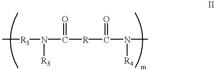


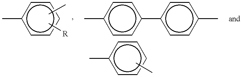


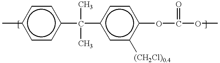


Claims (10)


Priority Applications (1)
| Application Number | Priority Date | Filing Date | Title |
|---|---|---|---|
| US09/487,288 US6340528B1 (en) | 2000-01-19 | 2000-01-19 | Crosslinkable polymer compositions for donor roll coatings |
Applications Claiming Priority (1)
| Application Number | Priority Date | Filing Date | Title |
|---|---|---|---|
| US09/487,288 US6340528B1 (en) | 2000-01-19 | 2000-01-19 | Crosslinkable polymer compositions for donor roll coatings |
Publications (1)
| Publication Number | Publication Date |
|---|---|
| US6340528B1 true US6340528B1 (en) | 2002-01-22 |
Family
ID=23935126
Family Applications (1)
| Application Number | Title | Priority Date | Filing Date |
|---|---|---|---|
| US09/487,288 Expired - Lifetime US6340528B1 (en) | 2000-01-19 | 2000-01-19 | Crosslinkable polymer compositions for donor roll coatings |
Country Status (1)
| Country | Link |
|---|---|
| US (1) | US6340528B1 (en) |
Cited By (18)
| Publication number | Priority date | Publication date | Assignee | Title |
|---|---|---|---|---|
| US20030067000A1 (en) * | 2001-09-04 | 2003-04-10 | Gabriele Nelles | Device having a solid conjugated semiconductor and method for preparing the same |
| US6682467B2 (en) * | 2000-09-18 | 2004-01-27 | Voith Paper Patent Gmbh | Elastic roll and method of making the roll |
| EP1403730A1 (en) * | 2002-09-30 | 2004-03-31 | Tokai Rubber Industries, Ltd. | Conductive roll |
| US6814890B2 (en) * | 2001-07-03 | 2004-11-09 | Xerox Corporation | Process for forming a mixed solvent adhesive solution |
| US20050106416A1 (en) * | 2003-11-14 | 2005-05-19 | Casasanta Vincenzo Iii | Process for preparing crosslinked polymer blends that include a luminescent polymer |
| US20050106417A1 (en) * | 2003-11-14 | 2005-05-19 | Casasanta Vincenzo Iii | Crosslinked polymer blends that include a luminescent polymer, and devices incorporating same |
| US20050107567A1 (en) * | 2003-11-14 | 2005-05-19 | Londergan Timothy M. | Poly(arylene ethers) with pendant crosslinkable groups, and devices incorporating same |
| US20050107568A1 (en) * | 2003-11-14 | 2005-05-19 | Baoquan Chen | Process for preparing poly(arylene ethers) with pendant crosslinkable groups |
| US20050107569A1 (en) * | 2003-11-14 | 2005-05-19 | Diyun Huang | Crosslinked compositions comprising a poly(arylene ether) and a nonlinear optical chromophore, and devices incorporating same |
| US20050208168A1 (en) * | 2004-03-18 | 2005-09-22 | Hickerson Kevin P | Apparatus for three dimensional printing using image layers |
| US20050256290A1 (en) * | 2003-10-07 | 2005-11-17 | General Electric Company | Monomers and polymers comprising conjugated groups and methods for making thereof |
| EP1725079A1 (en) * | 2004-03-11 | 2006-11-22 | Mitsubishi Chemical Corporation | Composition for charge-transporting film and ion compound, charge-transporting film and organic electroluminescent device using same, and method for manufacturing organic electroluminescent device and method for producing charge-transporting film |
| US20070237925A1 (en) * | 2006-04-07 | 2007-10-11 | Castle Scott R | Radiation cured coatings |
| US20090022902A1 (en) * | 2007-07-17 | 2009-01-22 | Mark William Johnson | Radiation cured coatings for image forming device components |
| US20100144916A1 (en) * | 2008-12-08 | 2010-06-10 | Sabic Innovative Plastics | Compositions having improved tribological properties, methods of manufacture thereof and articles comprising the same |
| CN1980988B (en) * | 2004-05-04 | 2010-12-15 | 沙伯基础创新塑料知识产权有限公司 | Halogen-free flame retardant polyamide composition with improved electrical and flammability properties |
| US20120201572A1 (en) * | 2011-02-09 | 2012-08-09 | Samsung Electronics Co., Ltd. | Roller for imaging apparatus and imaging apparatus including the roller |
| WO2021100809A1 (en) * | 2019-11-22 | 2021-05-27 | キヤノン株式会社 | Member for electrophotography, process cartridge, and electrophotographic image forming apparatus |
Citations (10)
| Publication number | Priority date | Publication date | Assignee | Title |
|---|---|---|---|---|
| US4338222A (en) | 1980-04-11 | 1982-07-06 | Xerox Corporation | Semiconductive organic compositions |
| US4868600A (en) | 1988-03-21 | 1989-09-19 | Xerox Corporation | Scavengeless development apparatus for use in highlight color imaging |
| US5172170A (en) | 1992-03-13 | 1992-12-15 | Xerox Corporation | Electroded donor roll for a scavengeless developer unit |
| US5264312A (en) | 1990-12-27 | 1993-11-23 | Xerox Corporatoin | Charge transporting layers formed from curable compositions |
| US5300339A (en) | 1993-03-29 | 1994-04-05 | Xerox Corporation | Development system coatings |
| US5583906A (en) | 1994-04-13 | 1996-12-10 | Kabushiki Kaisha Toshiba | Method of manufacturing rotating anode type X-ray tube |
| US5587224A (en) | 1995-03-27 | 1996-12-24 | Xerox Corporation | Developing apparatus including a coated developer roller |
| US5731078A (en) | 1995-05-30 | 1998-03-24 | Xerox Corporation | Developing apparatus and coated developer roller |
| US5976744A (en) | 1998-10-29 | 1999-11-02 | Xerox Corporation | Photoreceptor overcoatings containing hydroxy functionalized aromatic diamine, hydroxy functionalized triarylamine and crosslinked acrylated polyamide |
| US6004709A (en) * | 1998-12-22 | 1999-12-21 | Xerox Corporation | Allyloxymethylatedpolyamide synthesis compositions and devices |
-
2000
- 2000-01-19 US US09/487,288 patent/US6340528B1/en not_active Expired - Lifetime
Patent Citations (10)
| Publication number | Priority date | Publication date | Assignee | Title |
|---|---|---|---|---|
| US4338222A (en) | 1980-04-11 | 1982-07-06 | Xerox Corporation | Semiconductive organic compositions |
| US4868600A (en) | 1988-03-21 | 1989-09-19 | Xerox Corporation | Scavengeless development apparatus for use in highlight color imaging |
| US5264312A (en) | 1990-12-27 | 1993-11-23 | Xerox Corporatoin | Charge transporting layers formed from curable compositions |
| US5172170A (en) | 1992-03-13 | 1992-12-15 | Xerox Corporation | Electroded donor roll for a scavengeless developer unit |
| US5300339A (en) | 1993-03-29 | 1994-04-05 | Xerox Corporation | Development system coatings |
| US5583906A (en) | 1994-04-13 | 1996-12-10 | Kabushiki Kaisha Toshiba | Method of manufacturing rotating anode type X-ray tube |
| US5587224A (en) | 1995-03-27 | 1996-12-24 | Xerox Corporation | Developing apparatus including a coated developer roller |
| US5731078A (en) | 1995-05-30 | 1998-03-24 | Xerox Corporation | Developing apparatus and coated developer roller |
| US5976744A (en) | 1998-10-29 | 1999-11-02 | Xerox Corporation | Photoreceptor overcoatings containing hydroxy functionalized aromatic diamine, hydroxy functionalized triarylamine and crosslinked acrylated polyamide |
| US6004709A (en) * | 1998-12-22 | 1999-12-21 | Xerox Corporation | Allyloxymethylatedpolyamide synthesis compositions and devices |
Cited By (44)
| Publication number | Priority date | Publication date | Assignee | Title |
|---|---|---|---|---|
| US6682467B2 (en) * | 2000-09-18 | 2004-01-27 | Voith Paper Patent Gmbh | Elastic roll and method of making the roll |
| US6814890B2 (en) * | 2001-07-03 | 2004-11-09 | Xerox Corporation | Process for forming a mixed solvent adhesive solution |
| US7061009B2 (en) * | 2001-09-04 | 2006-06-13 | Sony International (Europe) Gmbh | Solid conjugated semiconductor device having an unmodified hole transport material |
| US20030067000A1 (en) * | 2001-09-04 | 2003-04-10 | Gabriele Nelles | Device having a solid conjugated semiconductor and method for preparing the same |
| US6918866B2 (en) | 2002-09-30 | 2005-07-19 | Tokai Rubber Industries, Ltd. | Conductive roll |
| EP1403730A1 (en) * | 2002-09-30 | 2004-03-31 | Tokai Rubber Industries, Ltd. | Conductive roll |
| US20040062940A1 (en) * | 2002-09-30 | 2004-04-01 | Tokai Rubber Industries, Ltd. | Conductive roll |
| US7652126B2 (en) * | 2003-10-07 | 2010-01-26 | General Electric Company | Monomers and polymers comprising conjugated groups and methods for making thereof |
| US20050256290A1 (en) * | 2003-10-07 | 2005-11-17 | General Electric Company | Monomers and polymers comprising conjugated groups and methods for making thereof |
| US7008556B2 (en) | 2003-11-14 | 2006-03-07 | Lumera Corporation | Process for preparing crosslinked polymer blends that include a luminescent polymer |
| US7196155B2 (en) | 2003-11-14 | 2007-03-27 | Lumera Corporation | Process for preparing poly(arylene ethers) with pendant crosslinkable groups |
| US20050107568A1 (en) * | 2003-11-14 | 2005-05-19 | Baoquan Chen | Process for preparing poly(arylene ethers) with pendant crosslinkable groups |
| US20050107567A1 (en) * | 2003-11-14 | 2005-05-19 | Londergan Timothy M. | Poly(arylene ethers) with pendant crosslinkable groups, and devices incorporating same |
| US7001678B2 (en) | 2003-11-14 | 2006-02-21 | Lumera Corporation | Crosslinked polymer blends that include a luminescent polymer, and devices incorporating same |
| US20050107569A1 (en) * | 2003-11-14 | 2005-05-19 | Diyun Huang | Crosslinked compositions comprising a poly(arylene ether) and a nonlinear optical chromophore, and devices incorporating same |
| US7038004B2 (en) | 2003-11-14 | 2006-05-02 | Lumera Corporation | Process for preparing poly(arylene ethers) with pendant crosslinkable groups |
| US20050106417A1 (en) * | 2003-11-14 | 2005-05-19 | Casasanta Vincenzo Iii | Crosslinked polymer blends that include a luminescent polymer, and devices incorporating same |
| US7067593B2 (en) | 2003-11-14 | 2006-06-27 | Lumera Corporation | Poly(arylene ethers) with pendant crosslinkable groups, and devices incorporating same |
| US20060142533A1 (en) * | 2003-11-14 | 2006-06-29 | Lumera Corporation | Process for preparing poly(arylene ethers) with pendant crosslinkable groups |
| US7087701B2 (en) | 2003-11-14 | 2006-08-08 | Lumera Corporation | Poly(arylene ethers) with pendant crosslinkable groups, and devices incorporating same |
| US7101957B2 (en) | 2003-11-14 | 2006-09-05 | Lumera Corporation | Crosslinked compositions comprising a poly(arylene ether) and a nonlinear optical chromophore, and devices incorporating same |
| US20050106416A1 (en) * | 2003-11-14 | 2005-05-19 | Casasanta Vincenzo Iii | Process for preparing crosslinked polymer blends that include a luminescent polymer |
| EP1725079A4 (en) * | 2004-03-11 | 2010-01-13 | Mitsubishi Chem Corp | Composition for charge-transporting film and ion compound, charge-transporting film and organic electroluminescent device using same, and method for manufacturing organic electroluminescent device and method for producing charge-transporting film |
| US8252432B2 (en) | 2004-03-11 | 2012-08-28 | Mitsubishi Chemical Corporation | Composition for charge-transporting film and ion compound, charge-transporting film and organic electroluminescent device using same, and method for manufacturing organic electroluminescent device and method for producing charge-transporting film |
| US7879461B2 (en) | 2004-03-11 | 2011-02-01 | Mitsubishi Chemical Corporation | Composition for charge-transporting film and ion compound, charge-transporting film and organic electroluminescent device using same, and method for manufacturing organic electroluminescent device and method for producing charge-transporting film |
| US20070207341A1 (en) * | 2004-03-11 | 2007-09-06 | Mitsubishi Chemical Corporation | Composition For Charge-Transporting Film And Ion Compound, Charge-Transporting Film And Organic Electroluminescent Device Using Same, And Method For Manufacturing Organic Electroluminescent Device And Method For Producing Charge-Transporting Film |
| US20110001134A1 (en) * | 2004-03-11 | 2011-01-06 | Mitsubishi Chemical Corporation | Composition for charge-transporting film and ion compound, charge-transporting film and organic electroluminescent device using same, and method for manufacturing organic electroluminescent device and method for producing charge-transporting film |
| EP1725079A1 (en) * | 2004-03-11 | 2006-11-22 | Mitsubishi Chemical Corporation | Composition for charge-transporting film and ion compound, charge-transporting film and organic electroluminescent device using same, and method for manufacturing organic electroluminescent device and method for producing charge-transporting film |
| US20050208168A1 (en) * | 2004-03-18 | 2005-09-22 | Hickerson Kevin P | Apparatus for three dimensional printing using image layers |
| WO2005089463A3 (en) * | 2004-03-18 | 2006-12-07 | Desktop Factory Inc | Apparatus for three dimensional printing using imaged layers |
| US7261542B2 (en) * | 2004-03-18 | 2007-08-28 | Desktop Factory, Inc. | Apparatus for three dimensional printing using image layers |
| CN1980988B (en) * | 2004-05-04 | 2010-12-15 | 沙伯基础创新塑料知识产权有限公司 | Halogen-free flame retardant polyamide composition with improved electrical and flammability properties |
| US20070237925A1 (en) * | 2006-04-07 | 2007-10-11 | Castle Scott R | Radiation cured coatings |
| US8017192B2 (en) | 2007-07-17 | 2011-09-13 | Lexmark International, Inc. | Radiation cured coatings for image forming device components |
| US20090022902A1 (en) * | 2007-07-17 | 2009-01-22 | Mark William Johnson | Radiation cured coatings for image forming device components |
| US20100144916A1 (en) * | 2008-12-08 | 2010-06-10 | Sabic Innovative Plastics | Compositions having improved tribological properties, methods of manufacture thereof and articles comprising the same |
| US9371426B2 (en) | 2008-12-08 | 2016-06-21 | Sabic Global Technologies B.V. | Compositions having improved tribological properties, methods of manufacture thereof and articles comprising the same |
| US20120201572A1 (en) * | 2011-02-09 | 2012-08-09 | Samsung Electronics Co., Ltd. | Roller for imaging apparatus and imaging apparatus including the roller |
| US9005093B2 (en) * | 2011-02-09 | 2015-04-14 | Samsung Electronics Co., Ltd. | Roller for imaging apparatus and imaging apparatus including the roller |
| CN102636971A (en) * | 2011-02-09 | 2012-08-15 | 三星电子株式会社 | Roller for imaging apparatus and imaging apparatus including the roller |
| CN102636971B (en) * | 2011-02-09 | 2016-08-03 | 三星电子株式会社 | The roller of imaging device, manufacture the method for this roller and include the imaging device of this roller |
| WO2021100809A1 (en) * | 2019-11-22 | 2021-05-27 | キヤノン株式会社 | Member for electrophotography, process cartridge, and electrophotographic image forming apparatus |
| CN114730149A (en) * | 2019-11-22 | 2022-07-08 | 佳能株式会社 | Electrophotographic member, process cartridge, and electrophotographic image forming apparatus |
| CN114730149B (en) * | 2019-11-22 | 2024-01-26 | 佳能株式会社 | Electrophotographic member, process cartridge, and electrophotographic image forming apparatus |
Similar Documents
| Publication | Publication Date | Title |
|---|---|---|
| US6340528B1 (en) | Crosslinkable polymer compositions for donor roll coatings | |
| US5681679A (en) | Overcoated electrophotographic imaging member with resilient charge transport layer | |
| US5830614A (en) | Multilayer organic photoreceptor employing a dual layer of charge transporting polymers | |
| JP3937836B2 (en) | Electrophotographic photosensitive member, process cartridge having the electrophotographic photosensitive member, and electrophotographic apparatus | |
| US5834080A (en) | Controllably conductive polymer compositions for development systems | |
| US5545499A (en) | Electrophotographic photoconductor having improved cycling stability and oil resistance | |
| JP2000191773A (en) | Allyloxymethylated polyamide, its synthesis and electrophotographic image forming member having the same | |
| US6300027B1 (en) | Low surface energy photoreceptors | |
| JP3551582B2 (en) | Electrophotographic photoreceptor | |
| EP1672007B1 (en) | Imaging member | |
| US6289196B1 (en) | Oxidized transport donor roll coatings | |
| JP5573191B2 (en) | Electrophotographic photosensitive member, process cartridge, and image forming apparatus | |
| US11599034B2 (en) | Electrophotographic photosensitive member, process cartridge and electrophotographic apparatus | |
| JP2000131863A (en) | Electrophotographic image forming member and its production | |
| EP0295115B1 (en) | Arylamine compounds | |
| JPH11327181A (en) | Organic electronic device | |
| JP3748928B2 (en) | Image forming method and photoreceptor for liquid development | |
| JP2644281B2 (en) | Electrophotographic photoreceptor | |
| JP3147319B2 (en) | Arylamine terpolymers having CF3 substituted moieties | |
| JP2022033542A (en) | Electrophotographic photoreceptor and method for manufacturing the same, and image forming apparatus | |
| US8728690B2 (en) | Spirodilactam-doped charge transport layer for imaging device | |
| JP2002318458A (en) | Electrophotographic photoreceptor, method for producing the same, electrophotographic process cartridge using the same and electrophotographic apparatus | |
| JP2610942B2 (en) | Electrophotographic photoreceptor | |
| JP2644279B2 (en) | Electrophotographic photoreceptor | |
| JP2644280B2 (en) | Electrophotographic photoreceptor |
Legal Events
| Date | Code | Title | Description |
|---|---|---|---|
| AS | Assignment |
Owner name: XEROX CORPORATION, CONNECTICUT Free format text: ASSIGNMENT OF ASSIGNORS INTEREST;ASSIGNORS:HSIEH, BING R.;YU, YUAN;FULLER, TIMOTHY J.;AND OTHERS;REEL/FRAME:010548/0501;SIGNING DATES FROM 19991222 TO 20000112 |
|
| STCF | Information on status: patent grant |
Free format text: PATENTED CASE |
|
| AS | Assignment |
Owner name: BANK ONE, NA, AS ADMINISTRATIVE AGENT, ILLINOIS Free format text: SECURITY INTEREST;ASSIGNOR:XEROX CORPORATION;REEL/FRAME:013153/0001 Effective date: 20020621 |
|
| AS | Assignment |
Owner name: JPMORGAN CHASE BANK, AS COLLATERAL AGENT, TEXAS Free format text: SECURITY AGREEMENT;ASSIGNOR:XEROX CORPORATION;REEL/FRAME:015134/0476 Effective date: 20030625 Owner name: JPMORGAN CHASE BANK, AS COLLATERAL AGENT,TEXAS Free format text: SECURITY AGREEMENT;ASSIGNOR:XEROX CORPORATION;REEL/FRAME:015134/0476 Effective date: 20030625 |
|
| FPAY | Fee payment |
Year of fee payment: 4 |
|
| FPAY | Fee payment |
Year of fee payment: 8 |
|
| FPAY | Fee payment |
Year of fee payment: 12 |
|
| AS | Assignment |
Owner name: XEROX CORPORATION, NEW YORK Free format text: RELEASE BY SECURED PARTY;ASSIGNOR:BANK ONE, NA;REEL/FRAME:034717/0200 Effective date: 20030625 Owner name: XEROX CORPORATION, NEW YORK Free format text: RELEASE BY SECURED PARTY;ASSIGNOR:JPMORGAN CHASE BANK, N.A.;REEL/FRAME:034715/0792 Effective date: 20061204 |
|
| AS | Assignment |
Owner name: XEROX CORPORATION, CONNECTICUT Free format text: RELEASE BY SECURED PARTY;ASSIGNOR:JPMORGAN CHASE BANK, N.A. AS SUCCESSOR-IN-INTEREST ADMINISTRATIVE AGENT AND COLLATERAL AGENT TO JPMORGAN CHASE BANK;REEL/FRAME:066728/0193 Effective date: 20220822 |