US6341201B1 - Remotely controllable camera system - Google Patents
Remotely controllable camera system Download PDFInfo
- Publication number
- US6341201B1 US6341201B1 US09/162,756 US16275698A US6341201B1 US 6341201 B1 US6341201 B1 US 6341201B1 US 16275698 A US16275698 A US 16275698A US 6341201 B1 US6341201 B1 US 6341201B1
- Authority
- US
- United States
- Prior art keywords
- camera body
- operation card
- data
- camera
- camera system
- Prior art date
- Legal status (The legal status is an assumption and is not a legal conclusion. Google has not performed a legal analysis and makes no representation as to the accuracy of the status listed.)
- Expired - Fee Related
Links
Images


Classifications
-
- G—PHYSICS
- G03—PHOTOGRAPHY; CINEMATOGRAPHY; ANALOGOUS TECHNIQUES USING WAVES OTHER THAN OPTICAL WAVES; ELECTROGRAPHY; HOLOGRAPHY
- G03B—APPARATUS OR ARRANGEMENTS FOR TAKING PHOTOGRAPHS OR FOR PROJECTING OR VIEWING THEM; APPARATUS OR ARRANGEMENTS EMPLOYING ANALOGOUS TECHNIQUES USING WAVES OTHER THAN OPTICAL WAVES; ACCESSORIES THEREFOR
- G03B17/00—Details of cameras or camera bodies; Accessories therefor
- G03B17/38—Releasing-devices separate from shutter
- G03B17/40—Releasing-devices separate from shutter with delayed or timed action
-
- G—PHYSICS
- G03—PHOTOGRAPHY; CINEMATOGRAPHY; ANALOGOUS TECHNIQUES USING WAVES OTHER THAN OPTICAL WAVES; ELECTROGRAPHY; HOLOGRAPHY
- G03B—APPARATUS OR ARRANGEMENTS FOR TAKING PHOTOGRAPHS OR FOR PROJECTING OR VIEWING THEM; APPARATUS OR ARRANGEMENTS EMPLOYING ANALOGOUS TECHNIQUES USING WAVES OTHER THAN OPTICAL WAVES; ACCESSORIES THEREFOR
- G03B2217/00—Details of cameras or camera bodies; Accessories therefor
- G03B2217/002—Details of arrangement of components in or on camera body
Definitions
- This invention relates to a photographic camera system and, in particular, to a remotely controllable camera system comprising a camera body and an operation card functioning as a lens cover.
- One of conventional types of cameras comprises a camera body equipped with all photographic functions and a camera cover or operation card attached to and detached from the camera body.
- a camera is known from, for example, Japanese Unexamined Patent Publication No. 7-244330.
- This camera cover incorporates a remote control system through which various types of exposures are made. Incorporating a remote control system into the camera cover enables the camera body to be structured small in overall size and provides improved portability of the camera.
- the camera cover is possibly often lost.
- the camera is not remotely operated through the camera cover but directly operated by operating a shutter release switch button equipped on the camera body, the camera cover remains detached from the camera body. In such an event, the camera cover is possibly lost, which leads to aggravation of portability.
- a camera system which comprises a camera body having at least an exposure means for making exposure and a lens cover type of operation card incorporating a function of operating the camera system which covers the taking lens when attached to the front of the camera body and is remotely operable to manipulate the camera system while remaining detached from the camera body.
- the operation card is attachable to one of exteriors of the camera body other than the front, for example the back most desirably, and enables the camera system to be operated through the operation card even while it is attached to the one exterior of the camera body.
- the camera system has an optical communication means provided between the camera body and the operation card which is enabled to operate when the operation card is attached to the one exterior of the camera body, for example, the back of the camera body.
- the camera system may have a display means such as a LCD panel installed to the operation card to display exposure data and/or operation data as a visual image thereon.
- the data may include a number of prints, a date, a time and a caption to be printed on a picture, data of exposure and camera operation, descriptions and directions relating to camera operation in different languages.
- the operation card as a lens or camera cover remains attached to the camera body during operating the camera system to take pictures, there is there is no fears that the operation card is lost. Further, even while the operation card functions as a remote control device even while it is detached from the camera, the camera body has no necessity to be equipped with various operation members but only necessity to have an essential operation element such as a main switch for powering on the camera system, which is always desirable to make the camera body simple in structure.
- the optical communication means avoids electrical parts such as electric contacts necessary to operationally couple the operation card and the camera body, in other words to provide intercommunication of information between the operation card and the camera body, which is always desirable to prevent the camera system from encountering operational errors even if the operation card is frequently attached to and detached from the camera body and ensures reliable intercommunication of information between them.
- the display means which is preferred to be installed to the operation card at one side which faces the taking lens of the camera body while attached to the front of the camera body, is advantageous to making the camera body small in size.
- FIG. 1 is a perspective view of a photographic camera in accordance with an embodiment of the invention
- FIG. 2 is a perspective view of a photographic camera in accordance with an another embodiment of the invention.
- FIG. 3 is a perspective view of a detachable operation card partly cut away
- FIG. 4 is a front view of the photographic camera
- FIG. 5 is a block diagram of a circuit installed in the photographic camera
- FIG. 6 is a block diagram of an electrical structure of the operation card
- FIG. 7 is an illustration showing a liquid crystal display panel of the operation card
- FIGS. 8A and 8B are a flow chart illustrating an initialization processing general sequence routine
- FIGS. 9A and 9B are a flow chart illustrating an operation card attaching processing sequence subroutine
- FIGS. 10A-10C are a flow chart illustrating a branch processing general sequence routine
- FIGS. 11A-11D are a flow chart illustrating a back side operation card attaching/detaching processing sequence routine
- FIG. 12 is a flow chart illustrating a front side operation card attaching/detaching processing sequence routine
- FIG. 13 is a flow chart illustrating a cartridge rid handling processing sequence routine
- FIGS. 14A-14C are a flow chart illustrating a cartridge rid handling processing control sequence routine
- FIGS. 15A and 15B are a flow chart illustrating a cartridge chamber rid opening processing sequence routine
- FIGS. 16A and 16B are a flow chart illustrating a main switch operation processing sequence routine
- FIG. 17 is a flow chart illustrating a main switch opening processing sequence routine
- FIGS. 18A and 18B are a flow chart illustrating a main switch closing processing sequence routine
- FIGS. 19A-19C are a flow chart illustrating a manual rewind processing sequence routine
- FIGS. 20A-20F are a flow chart illustrating a shutter release processing sequence routine
- FIG. 21 is a flow chart illustrating a second half shutter depression waiting processing sequence routine
- FIGS. 22A and 22B are a flow chart illustrating a self-timer shutter release processing sequence routine
- FIG. 23 is a flow chart illustrating an exposure processing sequence routine
- FIGS. 24A and 24B are a flow chart illustrating a remote control signal transmission processing sequence routine
- FIGS. 25A-25D are a flow chart illustrating a zooming signal transmission processing sequence routine
- FIGS. 26A-26C are a flow chart illustrating a zooming signal transmission processing sequence routine
- FIGS. 27A and 27B are a flow chart illustrating a flash charge processing sequence routine
- FIG. 28 is a flow chart illustrating a communication processing sequence routine
- FIGS. 29A and 29B are a flow chart illustrating a signal transmission processing sequence routine
- FIGS. 30A and 30B are a flow chart illustrating a signal reception processing sequence routine
- FIG. 31 is an illustration showing a signal structure
- FIG. 32 is a flow chart illustrating a card initialization processing sequence routine
- FIGS. 33A and 33B are a flow chart illustrating a card diverging processing sequence routine
- FIG. 34 is a flow chart illustrating an operation card attaching/detaching processing sequence routine
- FIGS. 35A through 35C are a flow chart illustrating an operation card flash mode processing sequence routine
- FIGS. 36A and 36B are a flow chart illustrating an operation card self-timer mode processing sequence routine
- FIGS. 37A and 37B are a flow chart illustrating an operation card remote control signal transmission processing sequence routine
- FIG. 38 is an illustration showing a structure of used in the operation card remote control signal transmission
- FIG. 39 is a flow chart illustrating a date mode setting processing sequence routine
- FIG. 40 is a flow chart illustrating a date mode changing processing sequence routine
- FIGS. 41A through 41D are a flow chart illustrating a date correction processing sequence routine
- FIGS. 42A through 42F are illustrations showing an indication of date mode change on the liquid crystal display (LCD) panel
- FIGS. 43A through 43I are a flow chart illustrating a print quantity (PQ) setting processing sequence routine
- FIGS. 44A and 44B are illustrations showing an indication of print quantity setting on the liquid crystal display (LCD) panel
- FIGS. 45A and 45B are illustrations showing an indication of print quantity setting on the liquid crystal display (LCD) panel
- FIGS. 46A through 46I are a flow chart illustrating a caption selection processing sequence routine
- FIGS. 47A through 47C are a flow chart illustrating a language selection processing sequence routine
- FIG. 48 is a flow chart illustrating a communication processing sequence routine
- FIGS. 49A and 49B are a flow chart illustrating a signal receiving processing sequence routine
- FIGS. 50A and 50B are a flow chart illustrating a signal transferring processing sequence routine.
- FIG. 51 is an illustration showing a signal structure.
- the invention may be applied to a photographic camera which is designed and adapted to use a conventional type of film contained in, for example, a cartridge having what is called a DX code.
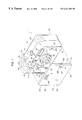
- the camera comprises a camera body 10 and a lens cover type operation card 60 detachably fixed to the camera body 10 .
- the operation card 60 incorporates a function of remotely operating the camera body 10 therein as will be described in detail later. Further the operation card 60 is designed and adapted as a lens cover to protect a taking lens and other element on the front of the camera body 10 while attached to the camera body 10 from the back.
- the operation card 60 is attached to the front of camera body 10 to cover the zoom lens 15 and also attached to one of camera exteriors such as the back 13 of camera body 10 .
- the operation card 60 attached to the back of the camera body 10 enables the photographer to operate and manipulate the camera system 1 .
- the camera body 10 which has a generally rectangularly-shaped outer appearance, is integrally formed with a semi-circular grip section 11 at one of its sides within which a cartridge chamber 54 is formed to receive a film cartridge 200 and other cartridges having special purposes such as cleaning magnetic read/write head.
- the semi-circular grip section 11 is swelled out from the remaining section and has front and back vertical shoulders 11 a and 11 b rising approximately perpendicularly from front and back walls 12 and 13 of the camera body, respectively.
- the vertical shoulders 11 a and 11 b catch finger tips of a hand which grasps the grip section 11 , so as to hold the camera body 10 tightly.
- the camera system 1 is equipped with a retractable taking lens such as a zoom lens 15 .
- the camera body 10 has a lens mount 14 defined by a circular opening 14 formed in the front wall 12 in which the retractable zoom lens 15 slides to protrude outward from and retract into the camera body 10 .
- the camera body 10 is provided with a flash emission window 16 for a built-in electronic flash unit, a window 17 behind which a light emitting element such as an LED and a projection lens of an automatic focusing system are placed, a self-timer window 18 , a viewfinder objective 19 and a window 20 behind which a photo-electric element and a lens of the automatic focusing system is placed. These windows are arranged in a approximately straight line above the lens mount 14 .
- the built-in electronic flash unit has a xenon tube disposed behind the flash emission window 16 .
- the automatic focusing system is of an active type, which comprises the light emitting element capable of projecting a light beam to a subject through the window 17 and the photo-electric element capable of receiving a reflected beam from the subject through the window 20 .
- a subject distance from the camera system 1 is found based on the received light.
- a light emitting element such as a light emitting diode (LED) is placed behind the self-timer window 18 to flush on and off while the camera system 1 is a self-timer exposure mode.
- LED light emitting diode
- the camera body 10 is further provided with a remote control window 21 and a light metering window 22 on one side of the lens mount 14 .
- a photo-electric element such as an infrared photo-diode forming part of a remote camera control system is placed behind the remote control window 21 to receive an infrared light beam from the operation card 60 .
- a photo-electric element such as a CdS is placed behind the light metering window 22 to receive light from the subject and detect the brightness of the subject.
- An automatic exposure system including a shutter mechanism automatically makes an exposure according to the brightness.
- the camera body 10 is further provided with a three-way print-type select switch 25 , a main switch 26 , a shutter release switch 27 and a display panel 28 in the top wall 24 .
- the three-way print type select switch 25 has three select positions for selecting and recording information concerning print types such as normal, high-vision and panoramic prints.
- the main switch 26 is of a push on-push off type which is pushed once to actuate the camera and pushed again to bring the camera into a standstill.
- the shutter release switch 27 has a two step stroke, namely a first half stroke for light metering and focusing and a second half stroke for actually making shutter release.
- the display panel 28 which is comprised of, for example, a liquid crystal display (LCD) element, for displaying information and/or marks or signs concerning camera operation, exposure, a battery and a cartridge.
- LCD liquid crystal display
- the camera body 10 has a fixing pin 23 which has a hemispheric head 23 a and extends forward from the front wall 12 at one end remote from the front vertical shoulder 11 a , positioning recesses 29 and 30 and a bore 31 formed in the front vertical shoulder 10 a .
- the fixing pin 23 and the positioning recesses 29 and 30 are engaged with a fixing bore 67 and positioning projections 63 and 64 provided on one side wall 62 of the operation card 60 , respectively, to detachably fix the operation card 60 to the camera body 10 .
- Electric terminals 63 a and 64 a are fixed to the positioning projections 63 and 64 , respectively.
- An attach/detach detection switch 32 is installed in the bore 31 to detect a pin 61 provided on one side wall 62 of the operation card 60 when the operation card 60 is fixed to the camera body 10 .
- the operation card 60 is fixed to the camera body 10 by inserting the pin 61 in the fixing bore 31 sideways and then snapping the fixing bore 67 on the fixing pin 23 .
- the operation card 60 has a retainer mechanism comprising a retainer 68 having a spring loaded V-shaped hook 68 a and a release switch button 66 .
- the spring loaded V-shaped hook 68 When the fixing pin 23 is inserted into the fixing bore 67 , the spring loaded V-shaped hook 68 is automatically brought into engagement with the underside of the hemispheric head 23 a of the fixing pin 23 to prevent the fixing pin 23 from escaping out from the fixing bore 67 .
- the spring loaded V-shaped hook 68 is forced sideways by pushing the release switch button 66 to allow the fixing pin 23 to come out of the fixing bore 67 .
- the camera body 10 at its back wall 13 is provided with a finder eyepiece 41 and a automatic focusing window 42 behind which a light emitting element such as an LED is placed.
- the finder eyepiece 41 is aligned with a window 69 formed in the operation card 60 while the operation card 60 is attached to the camera body 10 from the back 13 .
- the light emitting element flashes on and off to indicate that the zoom lens 15 on a subject while the shutter release switch 27 remains pushed half.
- the camera body 10 at its upper corner is provided with a cover 43 for closing an opening of a battery chamber (not shown) in which batteries are received.
- the camera body 10 further has a fixing pin 51 which has a hemispheric head 51 a and extends forward from the front wall 12 at one end remote from the back vertical shoulder 11 b , positioning recesses 44 and 45 and a bore 46 formed in the back vertical shoulder 11 b .
- the fixing pin 51 and the positioning recesses 44 and 45 are engaged with the fixing bore 67 and the positioning projections 63 and 64 of the operation card 60 , respectively, to detachably fix the operation card 60 to the camera body 10 from the back 13 .
- the spring loaded V-shaped hook 68 When the fixing pin 51 is inserted into the fixing bore 67 , the spring loaded V-shaped hook 68 is automatically brought into engagement with the underside of the hemispheric head 51 a of the fixing pin 51 to prevent the fixing pin 51 from escaping out from the fixing bore 67 .
- the spring loaded V-shaped hook 68 is forced sideways by pushing the release switch button 66 to allow the fixing pin 51 to come out of the fixing bore 67 .
- the camera body 10 is further formed with communication windows 48 and 49 between the positioning recesses 44 and 45 and a center recess 46 between the windows 48 and 49 formed in the back vertical shoulder 11 b .
- An attach/detach detection switch 47 is installed in the center recess 46 to detect the pin 61 on one side wall 62 of the operation card 60 when the operation card 60 is fixed to the camera body 10 from the back 13 .
- the camera body 10 is provided with a light emitting element 110 a such as an LED and a photo-electric element 110 b such as a photo-transistor (see FIG. 5) in the inside thereof. These light emitting element 110 a and photo-electric element 110 b are positioned behind the windows 48 and 49 , respectively.
- the grip section 11 at its back is provided with a zooming switch 50 for actuating a zooming mechanism (not shown) of the zoom lens 15 .
- the operation card 60 at the back 70 is provided with a liquid crystal display (LCD) panel 71 (which will be described in detail later) on which exposure information such as a date, an exposure mode, the number of prints and a caption are displayed according to signals from a microprocessor (CPU) 101 (see FIG. 5 ).
- LCD panel 71 there are provided various switches, namely a date mode select switch 72 , a caption select switch 73 , a print quantity select switch 74 , a flash exposure mode select switch 75 , a clear switch 76 and a remote control switch 77 arranged circularly in a clockwise direction in this order.
- the operation card 60 at the back 70 is provided with a cursor switch 80 comprised of an up-shift switch button 81 , a down-shift switch button 82 , a right-shift switch button 83 and a left-shift switch button 84 .
- FIG. 3 showing the external appearance of the side 62 of the operation card 60
- communication windows 91 and 92 corresponding in position to the communication windows 48 and 49 of the camera body 10
- a light emitting diode (LED) 93 disposed between the communication windows 91 and 92
- a pair of power switches disposed adjacent the positioning projections 63 and 64 , respectively.
- the operation card 60 incorporates a light emitting element 137 a (see FIG. 6) such as an light emitting diode (LED) inside the communication window 91 and a photo-electric element 137 b (see FIG.
- Optical communication is made between camera body 10 and the operation card 60 by means of the light emitting element 137 a in the operation card 60 and the photo-electric element 110 b in the camera body 10 through the communication windows 49 and 91 and by means of the light emitting element 110 a in the camera body 10 and the photo-electric element 137 b in the operation card 60 through the communication windows 48 and 92 .
- LED 93 projects a light beam when the remote control switch 77 is depressed while the operation card 60 is detached.
- Each power switch 94 is pushed in by the front vertical shoulder 11 a when the operation card 60 is attached to the camera body 10 from the front 12 or by the beck vertical shoulder 11 b when the operation card 60 is attached to the camera body 10 from the back 13 .
- the camera body 10 is provided with a cartridge chamber rid 52 for opening and closing a bottom opening of the cartridge chamber 54 formed in the grip section 11 .
- the cartridge chamber rid 52 is opened by an electrically controlled retaining and releasing mechanism not shown but well known in the art which is actuated by pushing a switch 53 .
- the camera body 10 is provided with a cartridge sensor 56 within the cartridge chamber 54 and a manual switch 55 at the bottom wall thereof.
- the cartridge sensor 56 is actuated by the top of a film cartridge 200 to indicates that the camera body 10 is loaded with a film cartridge when the film cartridge 200 is put in the cartridge chamber 54 and the cartridge chamber rid 52 is closed.
- the manual switch 55 is pushed to actuate an electrically controlled manual film rewinding mechanism.
- FIG. 5 shows CPU 101 in block diagram.
- CPU 101 is comprised of a microcomputer programmed to execute various control of the camera body 10 .
- CPU 101 is connected to various circuits, switches and optical and electrical elements such as a reset circuit (RST CKT) 102 , a booster circuit (BST CKT) 103 , a power circuit (PW CKT) 105 , a remote control signal receiving (RCSR CKT) circuit 106 , a group of switches 107 , a flash charging circuit (FLCH CKT) 108 , EEPROM 109 , LCD 28 , a communication unit 110 , LED unit 111 , an automatic focusing circuit (AF CKT) 112 , a lens drive circuit (LD CKT) 113 , a film advancing mechanism (FLAD MECH.) 114 , a DD read unit 115 , a shutter drive mechanism (SHD MECH.) 116 , a light metering (LMT) unit 117 , and a magnetic data read/
- CPU 101 incorporates ROM 101 a in which control and processing programs are stored, and RAM 101 b in which various data are stored during execution of the control and processing.
- CPU 101 receives commands or instructions by the photographer through the circuits, switches and optical and electrical elements to perform communication between the camera body 10 and the operation card 60 .
- the reset circuit (RST CKT) 102 provides a reset signal in response to powering on the camera system 1 to initialize the camera body 10 including CPU 101 .
- the booster circuit (BST CKT) 103 is connected to a battery 104 to boost a voltage supplied by the battery 104 under control by CPU 101 and delivers it to electrically controlled elements in the camera body 10 .
- the power circuit (PW CKT) 105 is connected at its output terminals to the electric terminals 44 a and 45 a installed in the positioning recesses 44 and 45 and is also connected at one of its input terminals to the booster circuit 103 .
- the voltage boosted by the booster circuit 103 is supplied to the power circuit 105 and then imparted to the operation card 60 through the electric terminals 44 a and 45 a under control by CPU 101 .
- the remote control signal receiving circuit (RCSR) 106 includes the photo-electric element placed behind the remote control window 21 to receive an infrared light beam from the light emitting diode (LED) 93 installed in the operation card 60 and sends optical data to CPU 101 .
- the group of switches 107 includes the main switch 26 through which an instruction is sent to CPU to switch the camera body 10 between a state ready for exposure and a state unsuited for exposure, the three-way print type select switch 25 , the shutter release switch 27 , the attach/detach detection switch 32 for detecting the operation card 60 attached to the camera body 10 from the front 12 , the attach/detach detection switch 47 for detecting the operation card 60 attached to the camera body 10 from the back 13 , the zooming switch 50 , the switch 53 for opening the cartridge chamber rid 52 , the manual film rewind switch 55 and the cartridge sensor 56 .
- the flash charging (FLCH CKT) circuit 108 includes the xenon tube disposed behind the flash emission window 16 which is excited to flash according to selected exposure modes under control by CPU 101 .
- EEPROM 109 stores data, for example, on the number of unexposed frames, current conditions of the camera system 1 and various control parameters.
- the communication unit 110 includes the light emitting element 110 a and the photoelectric element 110 b positioned behind the windows 48 and 49 , respectively, of the camera body 10 .
- optical communication is made between the photo-electric element 110 b in the camera body 10 and the light emitting element 137 a in the operation card 60 through the communication windows 49 and 91 and between the light emitting element 110 a in the camera body 10 and the photo-electric element 137 b in the operation card 60 through the communication windows 48 and 92 .
- optical data is sent from the camera body 10 to the operation card 60 under control by CPU 101 through the light emitting element 110 a of the communication unit 110 and the photo-electric element 137 b in the operation card 60 , and from the operation card 60 to the camera body 10 through the light emitting element 137 a in the operation card 60 to the photo-electric element 137 b of the communication unit 110 and then to CPU 101 .
- the LED unit 111 includes all LED elements including the LED placed behind the self-timer window 18 and the LED placed behind the automatic focusing window 42 in the camera body 10 which emit light beams under control by CPU 101 .
- the film advancing mechanism 114 unwinds and advances the film from the film cartridge 200 one frame every exposure and rewinds it into the film cartridge 200 .
- the data disk read unit 115 reads information relating to the film in the film cartridge 200 such as type and speed of the film, the number of available or unexposed frames of the film and information relating to whether the film is virgin, partly exposed, fully exposed or developed and sends the data to CPU 101 . These information are recorded in the form of bar codes on a data disk 201 (see FIG. 4) attached to the top of the film cartridge 200 . This data disk 201 changes its angular position relative to the cartridge 200 to indicate states of use of the film according to positions.
- the light metering unit 117 includes a photo-electric element such as a CdS placed behind the light metering window 22 to receive light from a subject and detect the brightness of the subject.
- the magnetic data read/write unit 118 writes data such as a date of exposure, the number of prints and a caption on a magnetic recording area associated with each frame of the film and reads the information.
- FIG. 6 shows a CPU 131 in block diagram which is comprised of a microcomputer programmed to execute various control of the operation card 60 and its associated electric elements.
- CPU 131 is connected to various circuits, switches and optical and electric elements such as a reset circuit (RST CKT) 132 , a regulator circuit (RGL CKT) 133 , a drive circuit (DRV CKT) 135 , a group of switches 136 , a communication unit 137 , LCD driver 138 , EEPROM 139 , and a remote control signal transfer circuit (RCSR CKT) 140 .
- CPU 101 incorporates ROM 131 a in which control and processing programs are stored and RAM 101 b in which various data are stored during execution of the control and processing.
- CPU 131 governs communication between the camera body 10 and the operation card 60 through these elements.
- the reset circuit 132 provides a reset signal in response to powering on the camera system 1 to initialize the operation card 60 including CPU 131 .
- the regulator 132 has input terminals which are connected to the electric terminals 63 a and 64 a fixed to the positioning projections 63 and 64 and between which the power switch 94 and a built-in battery 134 are in series.
- the power switch 94 turns on and off according to whether the operation card 60 is attached to the camera body 10 from the front 12 or the back 13 . That is, the power switch 94 remains turned on while the operation card 60 is detached from the camera body 1 and remains turned off while the operation card 60 is attached to the camera body 10 from the front 12 or the back 13 .
- the regulator circuit 133 stabilizes a source voltage supplied by the built-in battery 134 and delivers it to each electric element of the operation card 60 . While the power switch 94 is turned off by attaching the operation card 60 to the camera body 10 from the back 13 , the regulator circuit 133 receives a voltage supplied by the power circuit 105 and stabilizes and delivers it to each electric element of the operation card 60 . On the other hand, while the power switch 94 is turned off by attaching the operation card 60 to the camera body 10 from the front 12 , the regulator circuit 133 is supplied with no voltage by the power circuit 105 .
- the drive circuit 135 has an input terminal connected to the electric terminal 64 a positioned adjacent to the positioning projection 64 to detect a potential at the electric terminal 64 a based on which CPU 131 determines whether the operation card 60 is attached to the camera body 10 from the back 13 .
- the group of switches 136 includes the date mode select switch 72 , the caption select switch 73 , the print quantity select switch 74 , the flash exposure mode select switch 75 , the clear switch 76 , the remote control switch 77 and the cursor switch 80 .
- the date mode select switch 72 is used to select one of date display modes.
- the title select switch 73 is used to select one of a number of predetermined captions in different languages.
- the print quantity selection switch 74 is used to select the number of prints made from each exposed frame.
- the flash exposure mode select switch 75 is used to select one of various programmed exposure modes.
- the clear switch 76 is used to cancel selected data such as the number of prints and the caption and language.
- the remote control switch 77 is used to select one of control modes, namely a remote control mode in which the camera system 1 is remotely controlled by means of the operation card 60 detached from the camera body 10 and a self-timer mode in which an exposure is self-timed by means of the operation card 60 attached to the camera body 10 from the back 13 .
- the communication unit 137 which includes the light emitting element 137 a and the photo-electric element 137 b placed behind the communication windows 91 and 92 , and a drive circuit 137 c , makes optical communication between the camera body 10 and the operation card 60 while the operation card 60 remains attached to the camera body 10 from the back 13 .
- CPU 131 causes the light emitting element 137 a to provide optical signals to the photo-electric element 110 b in the camera body 10 .
- CPU 131 receives optical signals provided by the photo-electric element 110 a in the camera body 10 and detected by the light emitting element 137 a .
- Data transferred between the camera body 10 and the operation card 60 includes at least data necessary to control the operation card 60 and data relating an exposure mode, a language, a caption and print quantity.
- the drive circuit 137 c governs operation of the light emitting element 137 a and the photo-electric element 137 b under control by CPU 131 .
- the intercommunication between the camera body 10 and the operation card 60 is executed according to a specified protocol.
- an optical signal transferred between the camera body 10 and the operation card 60 is comprised of a header, a command, a data number and data “n” arranged in this order.
- the utilization of communication protocol ensures for data transmission with an effect of improving the reliability of optical communication.
- FIG. 7 shows an example of LCD panel 71 .
- LCD driver 138 which has display data RAM, character generating ROM (CGROM) and character generating RAM (CGRAM), drives LCD panel 71 to display information under control by CPU 131 .
- the display data RAM stores data as 8-bit character codes to display character strings or the like on dot matrix display areas 71 g and 71 h of LCD panel 71 .
- the CGROM stores a 5 ⁇ 8 dot character pattern (alphabets, Japanese “kanas”, simple patterns such as a rectangle, numerals) corresponding an 8-bit character code.
- the CGRAM stores eight character patterns which are not defined in a character set in the CGROM.
- Each character pattern is assigned as an 8-bit character code to a specified area in the CGROM and written in the data display RAM to be displayed on the dot matrix display area 71 g or 71 h of LCD panel 71 .
- a character string or the like displayed on the dot matrix display area 71 g or 71 h of LCD panel 71 can be scrolled from the right to the left bit by bit as viewed in FIG. 7 by LCD driver 138 under control by CPU 131 .
- Following shifting one of the character string another one of the character string appears from the right in the dot matrix display area 71 g or 71 h of LCD panel 71 , so that the whole character string is visibly displayed.
- the EEPROM 139 stores cartridge identification data (which is hereafter referred to as CID), and data of an exposure mode, a date mode, a language and a caption all of which are entered by the photographer.
- the remote control signal transfer circuit 140 includes the light emitting diode (LED) 93 installed in the operation card 60 and causes the light emitting diode (LED) 93 to sends optical data to the camera body 10 under control by CPU 131 .
- the optical data includes, for example, data relating exposure instructions, a language, a caption and print quantity.
- CPU 101 When a battery 104 is loaded in the camera body 10 with the operation card 60 attached to the front 12 of camera body 10 , power is supplied to CPU 101 through the booster circuit 103 and a reset signal is provided by the reset circuit 102 .
- CPU 101 receives the reset signal and initializes the camera body 10 and the operation card 60 . Specifically, CPU 101 , the RAM 101 b , the timer, the exposure mechanism including the zoom lens 15 and shutter are initialized. Further, parameters stored in the EEPROM 109 are read out and written in the RAM 101 b , and various elements are examined. In response to operation or depression of the main switch 26 or when it is detected through the attach/detach detection switch 47 that the operation card 60 is attached to the camera body 10 from the back 13 , CPU 101 activates the camera body 10 so as to be ready for exposure.
- the fact that the operation card 60 remains attached to the camera body 10 from the back 13 is recognized by CPU 101 of the camera body 10 through the attach/detach detection switch 47 and by CPU 131 of the operation card 60 through the drive circuit 135 .
- information entered through the group of switches 135 of the operation card 60 by the photographer are input into CPU 131 of the operation card 60 and then transferred in the form of optical data to CPU 101 of the camera body 10 through the communication units 137 and 110 .
- information entered through the group of switches 107 of the camera body 10 by the photographer are input into CPU 101 of the camera body 10 and then transferred in the form of optical data to CPU 131 of the operation card 60 through the communication units 137 and 110 .
- the fact that the operation card 60 remains detached from the camera body 10 is recognized by CPU 101 of the camera body 10 through the attach/detach detection switch 47 and by CPU 131 of the operation card 60 through the power switches 94 . While the operation card 60 remains detached from the camera body 10 , it serves as a remote controller or commander. When operating the switch buttons of the switch group 136 of the operation card 60 to enter information into CPU 131 of the operation card 60 , the information is instantaneously transferred in the form of optical data from the remote control signal transfer circuit 140 of the operation card 60 to the remote control signal receiving circuit 106 and then to CPU 101 of the camera body 10 .
- the data disk read unit 115 reads in CID data on the data disk 201 of the film cartridge 200 and transfers the CID data to the EEPROM 109 .
- the data are stored in the EEPROM 109 and referred every exposure.
- the manual film rewind switch 55 is operated, the film is forcedly rewound into the film cartridge 200 . Accordingly, the film cartridge 200 can be taken out of the camera body 10 even when the film is only partly exposed.
- the photographer can enter CID data and data on the number of unexposed frames into the EEPROM 139 of the operation card 60 .
- the film cartridge 200 containing a film only partly exposed can be reloaded in the camera body 10 .
- the data disk read unit 115 detects an angular position of the data disk 201 which indicates a state of use of the film. While the film is unwound out of the film cartridge 200 until a first unexposed frame is placed in an exposure position, the data read/write unit 118 reads magnetic data on the magnetic recording area of the film associated with each exposed frame.
- the camera system 1 is put operative and manipulated.
- the flash exposure mode select switch 75 is operated to select either one exposure mode. Further, if necessary, switches, for example, the caption select (ST) switch 73 , the print quantity select (PQ) switch 74 , the print type select switch 25 to select a language and a caption, a print quantity and a type of print, respectively. Data of the selected items are stored in RAM 131 b and simultaneously displayed on LCD panel 71 driven by LCD driver 138 . While the operation card 60 is attached to the camera body 10 from the back 13 , the shutter release switch 27 may be operated to make exposures.
- the shutter release switch 27 is turned off and the remote control switch 77 is activated to make exposures.
- the light metering unit 117 receives light from a subject and detect the brightness of the subject, and the automatic focusing mechanism 112 finds a subject distance from the camera body 10 .
- CPU 101 actuates the lens drive mechanism 113 to shift the zoom lens 15 according to the subject distance until focusing the zoom lens 15 on the subject.
- CPU 101 actuates the shutter drive mechanism 116 and the flash charging circuit 108 , if the flush exposure mode is selected, to make an exposure with flash light according to the subject brightness.
- CPU 101 actuates the film advancing mechanism 114 to advance one frame for another exposure.
- CPU 101 causes the data read/write unit 118 to write data such as a date of exposure, the number of prints and the selected caption in the selected language on the magnetic recording area associated with the exposed frame of the film.
- the operation card 60 is attached to the camera body 10 from the front 12 as a operation card to protect the zoom lens 15 and other optical elements and windows. If the camera system 1 remains inoperative with the operation card 60 attached to the front 12 of camera body 10 , it is left as inoperative. However, if the camera system 1 remains operative, it is automatically turned inoperative by attaching the operation card 60 to the camera body 10 from the front 12 . That is, CPU 101 detects the operation card 60 attached to the camera body 10 from the front 12 through the attach/detach detection switch 32 , CPU 101 is prohibited from providing an exposure command for the shutter drive mechanism 116 even when the shutter release switch 27 is operated.
- the operation card 60 is attached to the camera body 10 from the front 12 with LCD panel 71 and the switches 73 - 77 and cursor switch 80 put inside, LCD panel 71 and the switch 73 - 77 and 80 are protected from being damaged, and a simple external appearance of the camera system 1 is provided. Even if a large size of LCD panel 71 is installed to the operation card 60 , there is no fear of damages.
- the operation card 60 is detached from the camera body 10 .
- the operation card 60 is pulled up at the right side and then drawn to the right until the positioning projections 63 and 64 come out of the positioning recesses 29 and 30 , respectively.
- the camera system 1 is automatically put ready for exposure.
- the operation card 60 serves as a means for changing and/or notifying camera settings such as the time and the exposure mode.
- the operation card 60 is easily attached to the camera body 10 by engaging the positioning projections 63 and 64 with the positioning recesses 44 and 45 , respectively from the left as viewed in FIG. 2 and then pushing down it until the fixing pin 51 is received in the fixing bore 67 and engaged by the spring loaded V-shaped hook 68 .
- the operation card 60 is attached to the camera body 10 such that the back of the operation card 60 is accessed directly to operate the switch 73 - 77 and 80 .
- the switch 73 - 77 on the operation card 60 are operated to inter-communicate data between the operation card 60 and the camera body 10 .
- Through the switches of the operation card 60 it is made to select a date mode, an exposure mode and the remote control mode, to change the date, to enter or change CID, to display the CID, to set print quantity, to select a caption and a language for the caption, to register titles and captions, to reset or cancel print quantity for a previous exposed frame, and to rewrite or cancel a title or caption for a previous frame.
- the date mode select switch 72 is pushed to select date modes. When the date mode select switch 72 is pushed, a drive signal is provided by CPU 101 and sent to LCD driver 138 to drive LCD panel 71 to display characters and numerals. The date mode select switch 72 is continuously pushed until a desired date is displayed on LCD panel 71 .
- date display modes such as a date mode I in which a date in the form of year/month/day is displayed together with signs “F” and “B” which indicate that the date appears on front and back of a print, respectively, a date display mode II in which a time in the form of hour/minute is displayed together with the signs “F” and “B,” a date display mode III in which a date in the form of year/month/day is displayed together with the sign “B,” a date display mode IV in which a time in the form of hour/minute is displayed together with the sign “B,” a date display mode V in which CID data accompanied by a sign “ID-” is displayed, and a date display mode VI in which nothing is displayed.
- a date mode I in which a date in the form of year/month/day is displayed together with signs “F” and “B” which indicate that the date appears on front and back of a print, respectively
- a date display mode II in which a time in the form of hour/minute is displayed together with the signs “F
- CID data is displayed only when a CID entry condition is satisfied into EEPROM or when CID data has been registered in EEPROM.
- the date mode select switch 72 is repeatedly pushed, the date patterns in these six date modes are rotated on LCD panel 71 .
- the cursor switch 80 is operated after continuously pushing the date mode select switch 72 for a predetermined period of time, for example more than two seconds.
- the up-shift switch button 81 or the down-shaft switch button is pushed to rotate date display patterns of “year/month/day”, “month/day/year” and “day/month/year” in turn.
- the cursor switch 80 is operated.
- the flash exposure mode select switch 75 is pushed to select one of available flash exposure modes including a red-eye effect preventive flash exposure (PRE) mode in which the flash is fired several times immediately before an exposure, a coercive flash exposure (CFE) mode in which the flash is coercively fired at an exposure, a spontaneous exposure mode in which the flash is not used for an exposure, a distant view flash exposure (DVE) mode in which a subject at infinity is flash exposed, a night view flash exposure (NVE) mode in which a human figure in a night view is flash exposed, an auto-flash exposure (AFE) mode in which the flash is fired according to subjects, a print quantity setting mode and a caption selection mode.
- PRE red-eye effect preventive flash exposure
- CFE coercive flash exposure
- DVE distant view flash exposure
- NVE night view flash exposure
- AFE auto-flash exposure
- the flash exposure mode select switch 75 Whenever the flash exposure mode select switch 75 is continuously pushed, the available flash exposure modes are displayed on LCD panel 71 in turn and any one of them which is displayed before releasing the flash exposure mode select switch 75 is released. Further, the remote control switch 77 is pushed to select a self-timer exposure mode and a remote control mode.
- the print quantity (the number of copies) is selected by pushing the up-shift switch button 81 and/or the down-shift switch button 82 of the cursor switch 80 while pushing the print quantity select switch 74 .
- an initial value such as “P01” indicating one print is displayed on LCD panel 71 .
- the value is changed by an increment of one every time the up-shift switch button 81 is pushed, or changed by a decrement of one every time the down-shift switch button 82 is pushed.
- the up-shift switch button 81 and/or the down-shift switch button 82 of the cursor switch 80 are repeatedly pushed until a desired number of prints appears on LCD panel 71 .
- the value displayed is fixed and selected by pushing the date mode select switch 72 . While the print quantity select switch 74 is operated to select print quantity after the number of prints has been selected once, the clear switch 76 is pushed to display a date with an effect of cancelling the selected number of prints.
- Captions or titles and languages are selected by pushing the caption select switch 73 and the cursor switch 80 .
- the up-shift switch button 81 and/or the down-shift switch button 82 of the cursor switch 80 are repeatedly pushed to read out and display a great number of prepared captions, which are stored in ROM 131 a , one after another on the LCD panel 71 .
- the up-shift switch button 81 and/or the down-shift switch button 82 of the cursor switch 80 are repeatedly pushed to display the selected caption in various languages.
- the selected caption is automatically printed on a picture in the selected language.
- the captions can be registered in EEPROM 139 of the camera system 1 . Caption registration is made by pushing the caption select switch 73 while a specific caption is displayed on the LCD panel 71 by the use of the up-shift switch button 81 and/or the down-shift switch button 82 of the cursor switch 80 in the same manner as selecting the caption. Ten frequently used captions may be registered to enable the photographer to do quick selection of a caption.
- Print quantity change is executed by the use of the print quantity select switch 74 and the cursor switch 80 .
- a print quantity resetting mode is effected for the data relating to print quantity for the previous exposed frame can be rewritten.
- the old data for the previous exposed frame is replaced with data on the desired print quantity.
- a caption or title can be rewritten by the use of the caption select switch 73 and the cursor switch 80 .
- the data relating to the caption for the previous exposed frame can be rewritten.
- the up-shift switch button 81 and/or the down-shift switch button 82 of the cursor switch 80 until a desired caption or title is displayed on the LCD panel 71 and then pushing the left-shift switch button 84 again, the old caption or title for the previous exposed frame is replaced with the desired caption or title.
- the clear switch 76 is used to release the print quantity changing mode or the caption selection mode.
- the CPU 101 is put alive with an incoming signal from the attach/detach detection switch 47 to send a drive signal to the shutter drive mechanism 116 in response to depression of the shutter release switch 27 . Accordingly, there is no necessity to operate the main switch 26 separately from attaching the operation card 60 to the camera body 10 , which is always desirable for easy camera operation.
- the operation card 60 is detached from the camera body 10 . Specifically, while pushing the release switch button 66 to release the V-shaped hook 68 from the fixing pin 51 , the operation card 60 at its left end as viewed in FIG. 2 is pull up and then moved left.
- the pin 61 comes off the attach/detach detection switch 47 in the center recess 46 , so that a signal disappears to disable CPU 101 from providing any signal even when the shutter release switch 27 is operated or depressed. Accordingly, there is no necessity to operate the main switch 26 separately from detaching the operation card 60 from the camera body 10 , which is always desirable for easy camera operation.
- the operation card 60 When using the operation card 60 to control the camera body 10 remotely, the operation card 60 is detached from the camera body 10 .
- the operation card 60 projects an infrared light beam toward the camera body 10 when operating switches on the operation card 60 .
- the camera body 10 when detaching the operation card 60 from the back 13 of the camera body 10 after having pushed the remote control switch 77 once, the camera body 10 is put in a remote control mode to receive a infrared light beam from the operation card 60 through the remote control window 21 .
- various camera operations such as an exposure, print quantity selection, caption and/or language selection, data rewriting of print quantity and/or caption for the previous exposed frame and the like.
- Remote control photography is made through the operation card 60 detached from the camera body 10 .
- the light emitting diode (LED) 93 When directing the light emitting diode (LED) 93 toward the camera body 10 and pushing the remote control switch 77 , the light emitting diode (LED) 93 is excited to project a infrared light beam toward the camera body 10 , in particular, to the remote control window 21 . Then, the photo-electric element placed behind the remote control window 21 receives the infrared light beam and sends a control signal to the CPU 101 of the camera body 10 . According to the incoming control signal the CPU 101 actuates the shutter drive mechanism 116 to make exposure.
- Selection of a print quantity, a caption and its language, data rewriting of print quantity and/or caption for the previous exposed frame and the like are also remotely performed through the operation card 60 .
- the light emitting diode (LED) 93 projects a infrared light beam including instruction signals which are transferred to CPU 101 through the photo-electric element placed behind the remote control window 21 .
- signal transmission is performed by means of optical inter-communication between the camera body 10 and the operation card 60 remotely placed from the camera body 10 , other types of inter-communication system, such as a radio wave inter-communication system, may be incorporated.
- LCD panel 71 has a screen divided into three display areas, namely an upper display area with a row of graphic symbols 71 a - 71 f printed thereon which are selectively illuminated, a middle dot matrix display area 71 g on which a character string or the like, and a lower dot matrix display area 71 h on which a character string or the like.
- the row of printed symbols includes the red-eye effect preventive flash exposure (PRE) mode symbol 71 a which is illuminated when the camera system 1 is put in the red-eye effect preventive flash exposure (PRE) mode, a flash exposure mode symbol 71 b which is illuminated when the camera system 1 is put in the coercive flash exposure (CFE) mode or in the flash exposure prohibited mode, a distant view exposure (DVE) mode symbol 71 c which is illuminated when the camera system 1 is put in the distant view flash exposure (DVE) mode, a night view flash exposure (NVE) mode symbol 71 d which is illuminated when the camera system 1 is put in the night view flash exposure (NVE) mode, a self-timer exposure (STE) mode symbol 71 e which is illuminated when the camera system 1 is put in the night view exposure (NVE) mode, and a remote control mode symbol 71 f which is illuminated when the camera system 1 is put in the remote control mode, arranged in order from the left to the right.
- PRE red-
- the middle dot matrix display area 71 g displays characters and numerals stating a date and the like.
- the lower dot matrix display area 71 h displays a character string stating a selected caption in a selected language. Each character is comprised of a 5 ⁇ 8 dot character pattern of which data is stored in CGROM in LCD driver 138 .
- CID cartridge identification data
- available switch buttons 81 - 84 of the cursor switch 80 are indicated on the middle dot matrix display area 71 g , and CID data at every moment during cursor switch operation or CID data definitely finalized and the number of unexposed or available frames are displayed on the lower dot matrix display area 71 h.
- FIGS. 8A through 79 are flow charts illustrating various routines and subroutines for the microcomputer of CPU 101 and 131 .
- Programming a computer is a skill well understood in the art. The following description is written to enable a programmer having ordinary skill in the art to prepare an appropriate program for the microcomputer. The particular details of any such program would of course depend upon the architecture of the particular computer selected.
- FIGS. 8A and 8B which are a flow chart of the general sequence routine of data initialization processing of the camera body 10 which runs following loading a battery 104 in the camera body 10 .
- step S 101 CPU 101 is initialized to set initial values of a clock, a timer, registers and so forth and waits until the clock is stabilized. Subsequently, a judgement is made at step S 102 as to whether a condition for writing initial values into EEPROM 109 is satisfied. This initial value writing condition is satisfied when a plurality of the switch buttons of the switch group 107 have been operated and remain turned on. When the initial value writing condition is satisfied, a judgement is made at step S 103 as to whether the camera system 1 has been placed in condition for communication with an external apparatus.
- the external apparatus as used herein shall mean a special data entering and writing apparatus used to write data into EEPROM 109 during manufacturing the camera system 1 .
- step S 110 a judgement is made at step S 110 as to whether a spool key of the camera body 10 is in an exposed position.
- step S 111 another judgement is made based on a signal from the attach/detach detection switch 47 at step S 112 as to whether the operation card 60 is attached to the back 13 of the camera body 10 .
- an operation card attaching processing sequence subroutine is called for at step S 114 .
- a continuous film advancing processing sequence subroutine and an LCD panel display processing sequence subroutine are called for in order at steps S 115 and S 116 , respectively.
- the continuous film advancing processing after setting the camera body 10 in the date display mode I for printing a date of year, month and day on the back of a print, data including a date designating instruction or a mode reset instruction, a flush mode instruction and other instructions are transmitted to the operation card 60 by means of the inter-communication function.
- the LCD panel display processing after displaying all indications on LCD panel 71 for a specified period of time, indications as to the existence of a film cartridge 200 in the camera body 10 , the number of exposed frames and available battery power. Then, after the final step, the flow chart logic orders termination of the data initialization processing sequence routine and implements the branch to the branch processing sequence routine.
- FIGS. 9A and 10B are a flow chart of the operation card attaching processing sequence subroutine which takes place to confirm actuation of the operation card 60 when the operation card 60 is attached to the back 13 of the camera system 10 .
- the communication data input ports are set up to place the camera body 10 in condition for communication with the operation card 60 through the communication units 137 and 110 at step S 201 .
- a judgement is subsequently made at step S 202 as to whether an internal 250-ms count timer of CPU 101 is actuated to count a predetermined standard time of 250 milliseconds.
- This standard time is counted when confirming operation command and operation of the operation card 60 through communication with the camera body 10 .
- another internal 5-sec count timer is actuated at step S 203 to count a predetermined time of, for example, five seconds from a point of time at which the operation card 60 is attached to the camera body 10 from the back 13 .
- a confirmation request command is transferred to the operation card 60 through the communication units 110 and 137 to confirm whether there is no change in operated state of the operation card 60 .
- a judgement is made at step S 205 as to whether there is a command answer instructing no change in operated state from the operation card 60 .
- step S 207 If there is no command answer from the operation card, after waiting that the communication is brought into synchronism with the 250-ms timer at step S 206 , a judgement is made at step S 207 as to whether the 5-sec timer has counted up five seconds. Until the 5-sec count timer counts up five seconds, a confirmation request command is transferred to the operation card 60 .
- a CID display command is transferred to the operation card 60 through the communication units 110 and 137 at step S 209 .
- the command causes LCD panel 71 to display a sign of “CLEANING.” After displaying the sign, the flow chart logic orders termination of the branch processing sequence routine.
- a date display command is transferred to the operation card 60 through the communication units 110 and 137 .
- LCD panel 71 displays a film type of the film cartridge 200 loaded in the camera body 10 at step S 210 .
- a black-and-white film having an ISO film speed of 1600 is indicated as “b ISO 1600.”
- judgement is made at step S 211 as to whether the camera body 10 is in condition to permit data rewrite film rewind.
- a data rewrite film rewind permission command is transferred to the operation card 60 through the communication units 110 and 137 to permit data rewrite for the previous exposed frame through the operation card 60 at step 212 .
- a data rewrite film rewind prohibition command is transferred to the operation card 60 through the communication units 110 and 137 to prohibit data rewrite film rewind at step 213 .
- the flow chart logic orders return to the general sequence routine after the step in the general sequence routine calling for the operation card attaching processing sequence subroutine.
- the operation card 60 is automatically powered on in response to attaching the operation card 60 to the camera body 10 from the back 13 , which is accompanied by compulsory display of the type of a film in the cartridge 200 loaded in the camera body 10 on LCD panel 71 .
- FIGS. 10A through 10C are a flow chart of the branch processing sequence routine for implementing the branch to various processing of the camera body 10 following input signals from the camera switches or after a lapse of waiting time counted by timers, when the flow chart logic commences and control proceeds to a function block at step S 301 where clock processing is executed.
- clock processing the 250-ms count timer starts to count the seconds, and, when counting up 60 seconds, clock data are established in order of minute, hour, day, month and year and transferred to the operation card 60 through the communication units 110 and 137 .
- a judgement is made at step S 302 as to whether the camera system 1 is put in the remote control mode.
- the remote control signal receiving circuit 106 When the camera system 1 is not in the remote control mode, the remote control signal receiving circuit 106 is deenergized at step S 303 . On the other hand, when the camera system 1 is in the remote control mode, another judgement is made at step S 304 as to whether the flash unit has been charged up. If having not yet been charged up, the remote control signal receiving circuit 106 is deenergized at step S 303 . When the flash unit has been charged up, the remote control signal receiving circuit 106 is powered on and energized at step S 305 .
- the attach/detach detection switch 47 changes its state from an off-state to an on-state or vice versa, this indicate that the operation card 60 is attached to or detached from the back 13 of the camera body 10 , then the branch to back side operation card attaching/detaching processing is implemented.
- step S 308 a judgement is made at step S 308 as to whether the cartridge chamber rid 52 is either opened or closed. This judgement is made based on a change in state of a rid open/close detection switch (not shown). When the cartridge chamber rid 52 is opened or closed, then, the branch to rid opening/closing processing is implemented. When there is no operation of the cartridge chamber rid 52 , i.e. the cartridge chamber rid 52 remains open, at step S 309 , a judgement is made at step S 310 as to whether the spool key of the camera body 10 is in the exposed position.
- the spool key When it is out of the exposed position, then, the spool key is moved to the exposed position at step S 311 .
- the cartridge chamber rid 52 remains closed or when the spool key is in the exposed position while the cartridge chamber rid 52 remains open, judgements are made at steps S 312 and S 313 as to whether the main switch 26 is operated and whether the manual rewind switch 55 is operated.
- the main switch 26 When the main switch 26 is operated, the branch to main switch opening/closing processing is implemented.
- the manual rewind switch 55 When the manual rewind switch 55 is operated while the main switch 26 is not operated, then, the branch to manual film rewinding processing is implemented.
- step S 314 a judgement is made at step S 314 as to whether a sign “E” is displayed and sparkles as an indication of the frame count data and remains present on LCD panel 71 .
- the sign “E” remaining present on LCD panel 71 indicates that a film in the film cartridge 200 is completely exposed.
- step S 315 a judgement is made at step S 315 as to whether the sign “E” is flashing on and off on LCD panel 71 .
- the sign “E” flashing on and off on LCD panel 71 indicates that the film in the film cartridge 200 is improper for exposure for some reason.
- step S 316 a judgement is further made at step S 316 as to whether a numeral “N” is displayed and flashes on and off on LCD panel 71 .
- the numeral “N” displayed on LCD panel 71 indicates the number of exposable frames of a film in the cartridge 200 . If the numeral “N” displayed on LCD panel 71 flashes on and off indicates that an accident has occurred during advancing an exposed frame after having made a shutter release and it is impossible to make another exposure.
- a judgement is made at step S 317 as to whether the camera system 1 has been placed in condition for making exposure.
- step S 319 When the camera system 1 is in condition for exposure and the shutter release switch 27 is operated or depressed at step S 319 , the branch to shutter release controlling processing is implemented. However, if there is no operation of the shutter release switch 27 , a judgement is made at step S 320 as to whether the camera system 1 is in the remote control mode. When the camera system 1 is in the remote control mode, a judgement is made at step S 321 as to whether there is a remote control signal is transferred from the operation card 60 and received by the camera body 10 through the remote control signal receiving circuit 106 . When the remote control signal is received by the camera body 10 , the branch to remote control signal receiving processing is implemented.
- a judgements are subsequently made at steps S 322 and S 323 as to whether the zooming switch 50 is operated to shift the zoom lens 15 toward a telephoto end, namely to protrude the zoom lens from the camera body 10 or toward a wide-angle end, namely to retract the zoom lens 14 from the camera body 10 , respectively.
- the zoom switch 50 is operated to shift the zoom lens 15 toward the telephoto end, the branch to telephoto side zooming processing is implemented.
- the zoom switch 50 is operated to shift the zoom lens 15 toward the wide-angle
- the branch to wide-angle side zooming processing is implemented.
- the flow chart logic orders a restart of the branch processing sequence routine.
- FIGS. 11A through 11D are a flow chart of the back side operation card attaching/detaching processing sequence routine
- the flow chart logic commences and control proceeds to a decision at step S 401 as to whether the operation card 60 is attached to the camera body 10 from the back 13 . This decision is made based on a new appearance of a signal from the attach/detach detection switch 47 .
- the operation card attaching processing sequence subroutine shown in FIGS. 9A and 9B is run at step S 402 .
- step S 403 a judgement is made as to whether the operation card 60 remains attached.
- the flow chart logic orders termination of the back side operation card attaching/detaching processing sequence routine.
- the operation card 60 remains attached, in other words, when there is a signal from the attach/detach detection switch 47 remaining present, a flash mode instruction signal is transferred to the camera body 10 through the communication units 110 and 137 at step S 404 to compare the flash modes between the camera body 10 and the operation card 60 at step S 405 .
- a flash mode reset signal is transferred to the operation card 60 from the camera body 10 to reset the operation card 60 to the auto-flash exposure (AFP) mode at step S 406 , and simultaneously the camera body 10 resets itself to the auto-flash exposure (AFP) mode at step S 407 .
- PQ signal print quantity code signal
- ST selected caption
- the lens drive mechanism 113 is actuated to force the zoom lens 15 to return back to the retracted position at step S 414 .
- a judgement is made at step S 415 as to whether the zoom lens 15 has returned back to the retracted position.
- 9A and 9B is run at step S 417 . Subsequently, a command is transferred to the operation card 60 to reset it to initial mode at step S 418 , and then a command signal relating to flash mode is inter-communicated between the camera body 10 and the operation card 60 at step S 419 .
- step S 412 When the camera body 10 does not receive a selected caption (ST) code signal at step S 412 , or when the zoom lens 15 is not in the retracted position at step S 415 although it is forced to return to the position at step S 414 , or after transferred a command for displaying the print quantity or the selected caption on LCD panel 71 to the operation card 60 at step S 413 , or after transferred a command signal relating to flash mode between the camera body 10 and the operation card 60 at step S 419 , a judgement is made at step S 420 as to whether the camera system 1 is placed in condition for exposure.
- ST selected caption
- step S 421 a judgement is subsequently made at step S 421 as to whether the sign “E” displayed on LCD panel 71 remains sparkling or flashes on and off, or a numeral “N” displayed on LCD panel 71 flashes on and off.
- a mode change permission command is transferred to the operation card 60 to permit any change in available mode, as a result of which the operation card 60 is placed in condition for operation of the all switches and the like.
- the flow chart logic terminates the back side operation card attaching/detaching processing and orders return to the branch processing sequence routine after the step in the sequence routine calling for the back side operation card attaching/detaching processing sequence routine.
- the flow chart logic orders a jump to a function block at step S 422 where the power circuit 105 is shut off to power off the operation card 60 .
- a judgement is made at step S 424 as to whether the operation card 60 remains detached from the camera body 10 .
- steps S 425 and S 426 are subsequently made at steps S 425 and S 426 as to whether there is a magnetic head cleaning cartridge loaded in the camera body 10 and whether the camera system 1 is placed in the remote control mode, respectively.
- the lens drive mechanism 113 is actuated to force the zoom lens 15 to return back to the retracted position at step S 427 .
- a command relating to flash mode is transferred between the camera body 10 and the operation card 60 at step S 429 .
- the flow chart logic terminates the back side operation card attaching/detaching processing and orders return to the branch processing sequence routine after the step in the sequence routine calling for the back side operation card attaching/detaching processing sequence routine.
- the operation card 60 can be attached to the camera body 10 from the back 13 with an effect of automatically protruding the zoom lens 15 in condition for exposure camera system 1 , which is always desirable for easy and quick operation, and can be detached from the camera body 10 with an effect of automatically returning the zoom lens 15 in the camera body 10 , as a result of which the operation card 60 is quickly attached to the camera body from the front 12 . Further, when the operation card 60 is detached from the back 13 of the camera system 10 while the camera system 1 is in the remote control mode, the camera body 10 remains duly operative through the operation card 60 , which is always convenient for the photographer to start the use of the camera system 1 .
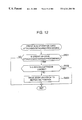
- FIG. 12 is a flow chart of the front side operation card attaching/detaching processing sequence routine
- the flow chart logic commences and control proceeds to a decision at step S 501 as to whether the operation card 60 is attached to the camera body 10 from the front 12 .
- This decision is made based on a signal from the attach/detach detection switch 32 .
- step S 502 is made at step S 502 as to whether the cartridge loaded in the camera body 10 is a magnetic head cleaning cartridge.
- the lens drive mechanism 113 is actuated to force the zoom lens 15 to return back to the retracted position at step S 503 .
- the flow chart logic terminates the front side operation card attaching/detaching processing and orders return to the branch processing sequence routine after the step in the sequence routine calling for the front side operation card attaching/detaching processing sequence routine.
- the execution of the front side operation card attaching/detaching processing causes the zoom lens 15 to automatically return back to the retracted position without operating the main switch 26 , which is always desirable for the photographer to terminate the use of the camera system 1 .
- FIG. 13 is a flow chart of the cartridge chamber rid opening/closing processing sequence routine
- the flow chart logic commences and control proceeds to a decision at step S 601 as to whether the cartridge chamber rid 52 is closed. Subsequently, a cartridge chamber rid closing processing is executed at step S 602 when it is closed, or a cartridge chamber rid opening processing is executed at step S 603 when it is opened.
- the flow chart logic terminates the cartridge chamber rid opening/closing processing and orders return to the branch processing sequence routine after the step in the sequence routine calling for the cartridge chamber rid opening/closing processing sequence routine.
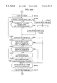
- FIGS. 14A through 14C are a flow chart of the cartridge chamber rid closing processing sequence routine
- the flow chart logic commences and control proceeds to a function block at step S 701 where a command is transferred to the operation card 60 through the communication units 110 and 137 to cancel setting of the self-timer exposure mode, the print quantity (PQ) code and selected caption (ST) code.
- a mode change prohibition command is transferred to the operation card 60 through the communication units 110 and 137 to prohibit any change in available mode at step S 702
- a clock data request command is transferred to the operation card 60 through the communication units 110 and 137 to request clock data at step S 703 .
- the operation card 60 transfers renewed clock data to the camera body 10 or a return signal indicating a conclusion of transfer of renewed clock data when the renewed clock data has been transferred. Further, the self-timer exposure mode and settings of the print quantity (PQ) code and selected caption (ST) code in RAM 101 b of CPU 110 are cancelled at step S 704 and S 705 , respectively. Subsequently, at step S 707 , after checking a voltage of the battery 104 at step S 706 , cartridge existence data is stored in RAM 101 b of CPU 110 when there is a cartridge signal indicating that a film cartridge 200 is loaded in the film cartridge chamber 54 from the cartridge sensor 56 or cartridge chamber empty data is stored in RAM 101 b of CPU 110 when there is no cartridge signal.
- PQ print quantity
- ST selected caption
- RAM 101 b of CPU 110 is accessed to find that the cartridge chamber 54 is loaded with a film cartridge 200 at step S 708 .
- CID cartridge identification data
- a CID data cancellation command is transferred to the operation card 60 through the communication units 110 and 137 to cancel the CID entry data at step S 711 .
- a judgement is made at step S 712 as to whether the camera is under visual exposure index (VEI) processing.
- a visual exposure index system is an unique system to indicate states of exposure of a film in the film cartridge 200 .
- the film cartridge 200 at one of its ends has four different cut-outs, such as a circular cut-out which effects an indication that the film is fresh or unexposed, a semi-circular cut-out which effects an indication that the film is partly exposed and partly unexposed, a cross-shaped cut-out which effects an indication that the film has been fully exposed but not yet processed in a film processing machine to develop the latent image on the exposed film, and a square cut-out which effects an indication that the film has been processed in a film processing machine to develop the latent image on the exposed film.
- any one of the visual exposure index cut-outs is positioned according to the state of exposure of the film so as to be viewed by the photographer through the visual exposure index (VEI) processing.
- a judgement is made at step S 713 as to whether the frame counter, whose data is stored in RAM 101 b of the CPU 101 , indicates “E” representing that no available or unexposed frames is left.
- the frame counter data indicates a numeral “N” representing a number of unexposed frames
- a judgement is further made at step S 714 as to whether there is no frame counter data to be stored in RAM 101 b of CPU 110 .
- storing the frame counter data is stored as VEI data for “fully exposed” in EEPROM 109 of CPU 110 at step S 715 , film rewinding processing is executed to actuate the film advancing mechanism 114 to rewind the film into the film cartridge 200 at step S 716 .
- the visual exposure index (VEI) processing is executed.
- step S 713 When it is judged at step S 713 that the frame counter indicates “E” representing that no available or unexposed frames is left or after storing the frame counter data for “E” at step S 718 , data is written in EEPROM 109 to renew initial data including an ISO film speed, a film type and an initial frame counter value at step S 719 . Subsequently, a data rewrite film rewind permission command is removed at step S 720 , and a data rewrite film rewind prohibition command is transferred to the operation card 60 through the communication units 110 and 137 at step S 721 . When the operation card 60 receives the data rewrite film rewind prohibition command, the operation card 60 is put impossible to receive a film rewinding signal.
- a date display command and data of a date are transferred to the operation card 60 at step S 722 , and then, LCD panel 28 is deenergized to remove an indication of frame counter data for a numeral “N” representing the number of unexposed frames at step S 723 .
- step S 714 When it is judged at step S 714 that there is no frame counter data to be stored in RAM 101 b of CPU 110 , after deenergizing LCD panel 28 to remove an indication of frame counter data for a numeral “N” representing the number of available or unexposed frames at step S 724 , a date display command and data of a date are transferred to the operation card 60 at step S 725 . Subsequently a judgement is made at step S 726 as to whether the camera system 1 is under DEP-DD processing.
- the DEP-DD processing is executed to read information on the film cartridge 200 , which includes an ISO film speed, a film type and available exposures, put on the data disk 201 of a film cartridge 200 loaded in the camera body 10 by means of the data disk read unit 115 and one of the visual exposure indices (VEI) of the film cartridge 200 .
- the cartridge information is factory printed in the form of bar codes on the film cartridge 200 .
- the visual exposure index (VEI) processing is executed at step S 730 .
- step S 716 Subsequently to execution of the film rewinding processing at step S 716 , execution of the first frame positioning (FFS) processing at step S 728 or the visual exposure index (VEI) processing, or after removing an indication of frame counter data for a numeral “N” at step S 723 , a judgement is made at step S 731 as to whether the camera system 1 has been placed in condition for exposure.
- the flow chart logic terminates the cartridge chamber rid closing processing and orders return to the branch processing sequence routine after the step in the sequence routine calling for the cartridge chamber rid opening/closing processing sequence routine.
- step S 732 when the camera system 1 is in condition for exposure, another judgement is subsequently made at step S 732 as to whether the sign “E” displayed on LCD panel 71 remains sparkling or flashes on and off, or a numeral “N” displayed on LCD panel 71 flashes on and off.
- a mode change permission command is transferred to the operation card 60 to permit any change in available mode at step S 733 .
- the flow chart logic terminates the cartridge chamber rid closing processing and orders return to the branch processing sequence routine after the step in the sequence routine calling for the cartridge chamber rid opening/closing processing sequence routine.
- FIGS. 15A and 15B are a flow chart of the cartridge chamber rid opening processing sequence routine
- a cancellation command is transferred to the operation card 60 through the communication units 110 and 137 to cancel setting of the self-timer exposure mode, the print quantity (PQ) code and the selected caption (ST) code.
- a mode change prohibition command is transferred to the operation card 60 through the communication units 110 and 137 to prohibit any change in available mode at step S 802
- a clock data request command is transferred to the operation card 60 through the communication units 110 and 137 to request the operation card 60 to transfer clock data at step S 803 .
- step S 804 After checking a power level of the battery 104 at step S 804 , the self-timer exposure mode and settings of the print quantity code and the caption code in RAM 101 b of CPU 110 are cancelled at step S 805 and S 806 , respectively. Subsequently, at step S 807 , it is detected based on a cartridge signal from the cartridge sensor 56 that a film cartridge 200 exists in the film cartridge chamber 54 .
- the cartridge signal is stored as cartridge existence data in RAM 101 b of CPU 110 . If there is no cartridge signal, cartridge chamber empty data is stored in RAM 101 b of CPU 110 .
- RAM 101 b of CPU 110 is accessed to find that the cartridge chamber 54 is loaded with a film cartridge 200 or empty at step S 608 .
- a judgement is made at step S 809 as to whether there is no frame counter data to be stored in RAM 101 b of CPU 101 .
- a further judgement is made at step S 810 as to whether the frame counter data indicates a numeral “N” representing the number of unexposed frames.
- a display removal command is stored in RAM 101 b of CPU 101 of the camera body 10 to turn off the cartridge symbol, on LCD panel 28 and the cartridge sign is turned off at step S 811 .
- data is written in EEPROM 109 to renew initial information including an ISO film speed, a film type and an initial frame counter value “N” at step S 813 .
- a data rewrite film rewind permission command is removed at step S 814 , and a data rewrite film rewind prohibition command is transferred to the operation card 60 through the communication units 110 and 137 at step S 815 .
- a judgement is made at step S 817 as to whether the number of available or unexposed frames represented by the frame counter data to be stored in RAM 101 b of CPU 101 , is equal to the initial frame counter value of “N”. When the number of available or unexposed frames is equal to a specified number of “N,” the number of available or unexposed frames, i.e.
- the specified number of “N,” is displayed on LCD panel 28 of the camera body 10 at step S 818 .
- the cartridge identification data (CID) including data of the number of unexposed frames is transferred to the operation card 60 through the communication units 110 and 137 at step S 819 , and a frame count display command is transferred to the operation card 60 through the communication units 110 and 137 to display the number of unexposed frames on LCD panel 71 of the operation card 60 at step S 820 .
- step S 808 When there is the cartridge existence data in RAM 101 b of CPU 110 as a result of an access to RAM 101 b of CPU 110 at step S 808 or when there is the frame counter data indicating a numeral “N” representing the number of unexposed frames in RAM 101 b of CPU 110 as a result of an access to RAM 101 b of CPU 110 at step S 810 while there is the cartridge empty data in RAM 101 b of CPU 110 , or when the number of unexposed frames is not equal to the specified number of “N” at step S 817 , or after displaying the number of unexposed frames on LCD panel 71 of the operation card 60 at step S 820 , a judgement is made at step S 821 as to whether the camera system 1 has been placed in condition for exposure.
- step S 822 When the camera system 1 is in condition for exposure, another judgement is subsequently made at step S 822 as to whether the sign “E” displayed on LCD panel 71 sparkles or flashes on and off, or a numeral “N” displayed on LCD panel 71 flashes on and off.
- a mode change permission command is transferred to the operation card 60 to permit any change in available mode at step S 823 .
- the flow chart logic terminates the cartridge chamber rid opening processing and orders return to the branch processing sequence routine after the step in the sequence routine calling for the cartridge chamber rid opening/closing processing sequence routine.
- the camera system 1 automatically advances a film and is placed in condition for exposure in response to closing the cartridge chamber rid 52 following loading the film cartridge 200 in the cartridge chamber 54 . Further, when the cartridge chamber rid 52 is opened and there is no film cartridge in the cartridge chamber 54 , the camera body 10 is automatically put ready for another film cartridge loading, which is always desirable for the photographer to use the camera system 1 .
- FIGS. 16A and 16B are a flow chart of the main switch operation processing sequence routine which is called for in response to a main switch operation
- the flow chart logic commences and control proceeds directly to a function block at step S 901 where a judgement is made based on a signal from the attach/detach detection switch 32 as to whether the operation card 60 has been attached to the front 12 of the camera body 12 .
- a judgement is made at step S 902 as to whether a specified reserve time of, for example, five minutes has passed before any active operation of, for example, switches, of the camera system 1 .
- LCD panel 28 of the camera body 10 is energized to display the number of available frames of the film in the film cartridge 200 loaded in the camera body 10 at step S 903 when the specified reserve time expires without any active operation of the camera system 1 and subsequently the cartridge symbol at step 904 only when there is a signal from the cartridge sensor 56 . Further, LCD panel 28 displays a battery symbol to indicate the power level of the battery 104 in the camera body 10 at step 905 . Thereafter, at step S 906 , clock data setting processing is executed to establish data of date in order of minute, hour, day, month and year when the 250-ms count timer counts up 60 seconds and to transfer the data of date to the operation card 60 through the communication units 110 and 137 .
- This date data is repeatedly established while the main switch 26 remains operated at step S 907 .
- the flow chart logic terminates the main switch opening/closing processing and orders return to the branch processing sequence routine after the step in the sequence routine calling for the main switch opening/closing processing sequence routine.
- encoder checking processing is executed to detect a position of the zoom lens 15 at step S 911 . Based on a result of the encoder checking processing, a judgement is made at step S 912 as to whether the zoom lens 15 is in the retracted position. Subsequently to the judgement, main switch opening processing is executed at step S 913 when the zoom lens 15 is in the retracted position, or main switch closing processing is executed at step S 914 when the zoom lens 15 is out of the retracted position.
- a judgement is made based on a signal from the attach/detach detection switch 32 at step S 915 as to whether the operation card 60 is attached to the front 12 of the camera body 12 .
- the clock data setting processing is executed to establish data of date in order of minute, hour, day, month and year at step S 917 .
- step S 915 and the clock data setting processing at step S 917 are repeated while the main switch 26 remains operated.
- the flow chart logic terminates the main switch opening/closing processing and orders return to the branch processing sequence routine after the step in the sequence routine calling for the main switch opening/closing processing sequence routine.
- FIG. 17 is a flow chart of the main switch opening processing sequence routine
- a mode change prohibition command is transferred to the operation card 60 to prohibit any change in available mode.
- a clock data request command is transferred to the operation card 60 through the communication units 110 and 137 to request the operation card 60 to transfer clock data at step S 1002 .
- the power level is compared with a threshold level to determine that the battery 104 is no good for use at step S 1004 .
- opening processing is executed to actuate the lens drive mechanism 113 to shift the zoom lens 15 to a predetermined position for taking a picture at step S 1005 .
- the encoder checking processing is executed to detect a position of the zoom lens 15 at step S 1006 . Based on a result of the encoder checking processing, a judgement is made at step S 1007 as to whether the zoom lens 15 is in the retracted position.
- the flow chart logic terminates the main switch opening processing.
- RAM 101 b of CPU 101 is accessed to judge whether there is a main switch open code in RAM 101 b of CPU 101 at step S 1010 .
- a judgement is subsequently made at step S 1011 as to whether the sign “E” displayed on LCD panel 71 sparkles or flashes on and off, or a numeral “N” displayed on LCD panel 71 flashes on and off.
- a mode change permission command is transferred to the operation card 60 to permit any change in available mode at step S 1012 .
- the flow chart logic terminates the main switch opening processing.
- FIGS. 18A and 18B are a flow chart of the main switch closing processing sequence routine, when the flow chart logic commences and control proceeds directly to a function block at step S 1101 where a mode reset command is transmitted to the operation card 60 through the communication units 110 and 137 to cancel all available mode. Subsequently, a mode change prohibition command is transferred to the operation card 60 through the communication units 110 and 137 to prohibit any change in available mode at step S 1102 , and a clock data request command is transferred to the operation card 60 through the communication units 110 and 137 to request the operation card 60 to transfer clock data at step S 1103 . A judgement is made at step S 1104 as to whether the camera system 10 has been put in the red-eye effect preventive flash exposure (PRE) mode.
- PRE red-eye effect preventive flash exposure
- step S 1105 When the camera body 10 is in the red-eye effect preventive flash exposure (PRE) mode, or after putting the camera body 10 in the auto-flash exposure (AFE) mode at step S 1105 when it is not in the red-eye effect preventive flash exposure (PRE) mode, data of the print quantity (PQ) and selected caption (ST) and data of the self-timer exposure mode in RAM 101 b of CPU 101 are removed at step S 1106 and S 1107 , respectively. Subsequently, closing processing is executed to actuate the lens drive mechanism 113 to shift back the zoom lens 15 to the a retracted position at step S 108 . After execution of the opening processing, the encoder checking processing is executed to detect a position of the zoom lens 15 at step S 1109 .
- step S 1110 Based on a result of the encoder checking processing, a judgement is made at step S 1110 as to whether the zoom lens 15 is in the retracted position.
- the zoom lens 15 is in the retracted position, after setting a main switch close code indicating that the camera system 1 is not in condition for exposure is stored in RAM 101 b of CPU 101 at step S 1111 , the flow chart logic terminates the main switch closing processing.
- RAM 101 b of CPU 101 is accessed to judge whether there is a main switch open code in RAM 101 b of CPU 101 at step S 1113 .
- a judgement is subsequently made at step S 1114 as to whether the sign “E” displayed on LCD panel 71 sparkles or flashes on and off, or a numeral “N” displayed on LCD panel 71 flashes on and off.
- a mode change permission command is transferred to the operation card 60 to permit any change in available mode at step S 1115 .
- the flow chart logic terminates the main switch closing processing.
- the main switch opening/closing processing By execution of the main switch opening/closing processing, it is possible to notify existence of a film cartridge, the number of unexposed frames and the power level of a battery by operating the main switch 26 even while the operation card 20 remains attached to the front 12 of the camera body 10 . Further, the camera system 1 is automatically put in the red-eye effect preventive flash exposure (PRE) mode at the end of use, which is always desirable for the photographer to use the camera system 1 .
- PRE red-eye effect preventive flash exposure
- FIGS. 19A through 19C are a flow chart of the manual film rewinding processing sequence routine called for in response to operation of the manual rewind switch 55 , when the flow chart logic commences and control proceeds directly to a function block at step S 1201 where a reset command is transferred to the operation card 60 through the communication units 110 and 137 to cancel the self-timer exposure mode, the print quantity (PQ) and the number of unexposed frames (ST).
- a reset command is transferred to the operation card 60 through the communication units 110 and 137 to cancel the self-timer exposure mode, the print quantity (PQ) and the number of unexposed frames (ST).
- a mode change prohibition command is transferred to the operation card 60 through the communication units 110 and 137 to prohibit any change in available mode at step S 1202
- a clock data request command is transferred to the operation card 60 through the communication units 110 and 137 to request the operation card 60 to transfer clock data at step S 1203 .
- step S 1208 When the cartridge chamber rid 52 has been closed, detection of a film cartridge 200 loaded into the cartridge chamber 54 of the camera body 10 is made based on a signal from the cartridge sensor 56 at step S 1208 . Data of existence or absence of a film cartridge is stored in RAM 101 b of CPU 101 .
- RAM 101 b is accessed to judge whether there is the data of the number of unexposed frames at step S 1209 . If there is no data of the number of unexposed frames, another judgement is subsequently made at step S 1210 as to whether the camera body 10 has been loaded with a film cartridge 200 .
- step S 1215 when there is the data of the number of unexposed frames in RAM 101 b , or when there is a film cartridge 200 loaded in the cartridge chamber 54 while there is no data of the number of unexposed frames in RAM 101 b , a judgement is made at step S 1215 as to whether the cartridge chamber rid 52 remains open. When the cartridge chamber rid 52 has been closed, a judgement is made at step S 1216 as to whether the visual exposure index (VEI) system indicates a semi-circular cut-out in the data disk 201 of the film cartridge 200 indicating that the film in the film cartridge 200 is partly exposed and partly unexposed at step S 1216 .
- VAI visual exposure index
- RAM 101 b of CPU 101 is accessed to make judgements as to whether there is data representing the sign “E” that indicates that the film in the film cartridge 200 has no available or unexposed frames at step S 1217 and whether there is data representing “N” that indicates a number of available or unexposed frames of the film in the film cartridge 200 at step S 1218 , respectively.
- RAM 101 b of CPU 101 is further accessed to judge whether there is data representing that the sign “N” should flash on and off at step S 1219 .
- a frame counter data is stored as cartridge identification data (CID) indicating no available unexposed frames in RAM 101 b of CPU 101 at step S 1220 .
- a frame counter data is stored as cartridge identification data (CID) indicating a number of available unexposed frames in RAM 101 b of CPI 101 at step S 1221 .
- the film rewind processing is executed, in which the film advancing mechanism 114 is actuated to rewind the whole length of film into the film cartridge 200 and the visual exposure index (VEI) system is actuated to show the semi-circular cut-out in the data disk 201 of the film cartridge 200 at step S 1222 .
- VEI visual exposure index
- the operation card 60 remains detached, or after execution of the front side operation card attaching/detaching processing at step S 1227 when the operation card 60 is attached to the camera body 10 from the front 12 , after execution of the clock data setting processing at step S 1228 another judgement is made at step S 1229 as to whether the main switch 26 remains operated.
- the flow chart logic orders return to the step of the decision concerning attaching the operation card 60 to the camera body 10 from the front 12 made at step S 1226 .
- RAM 101 b of CPU 101 is accessed to judge whether there is a main switch open code in RAM 101 b of CPU 101 at step S 1230 .
- a judgement is subsequently made at step S 1231 as to whether the sign “E” displayed on LCD panel 71 sparkles or flashes on and off, or a numeral “N” displayed on LCD panel 71 flashes on and off.
- a mode change permission command is transferred to the operation card 60 to permit any change in available mode at step S 1233 .
- the flow chart logic terminates the manual film rewinding processing and orders return to the branch processing sequence routine after the step in the sequence routine calling for the manual film rewinding processing sequence routine.
- FIGS. 20A through 20F are a flow chart of the shutter controlling processing sequence routine called for in response to operation of the shutter release switch 27 .
- the shutter release switch 27 has a two step stroke, i.e. the first half stroke (which is hereafter referred to as the SP 1 stroke) for subject distance metering and focusing and the second half stroke (which is hereafter referred to as the SP 2 stroke) for an exposure.
- step S 1301 a mode change permission command is transferred to the operation card 60 through the communication units 110 and 137 to prohibit any change in available mode.
- the encoder checking processing is executed to detect whether the zoom lens 15 has been put in the retracted position at step S 1302 .
- the power level is compared with a threshold level to determine that the battery 104 is no good (NG) for use at step S 1304 .
- a clock data request command is transferred to the operation card 60 through the communication units 110 and 137 to request the operation card 60 to transfer clock data at step S 1305 .
- the operation card 60 transfers renewed clock data to the camera body 10 or a return signal indicating a conclusion of transfer of clock data renewal when the renewed clock data has been transferred.
- a flash mode request command is transferred to the operation card 60 through the communication units 110 and 137 to request the operation card 60 to transfer data on a flash mode set in the operation card 60 at step S 1306
- a self-timer exposure mode request command is transferred to the operation card 60 through the communication units 110 and 137 to request the operation card 60 to transfer data on the self-timer exposure mode to the camera body 10 at step S 1307 .
- the operation card 60 transfer data on the flash exposure mode and the self-timer exposure mode through the communication units 110 and 137 at step S 1306 and S 1307 , respectively.
- a temperature of the camera body 10 is detected by a temperature sensor (not shown) installed in the camera body 10 at step S 1308 , the light metering unit 117 is actuated to receive light from a subject through the light metering window 22 to detect the brightness of the subject at step S 1309 , and the automatic focusing (AF) processing is executed to detect a subject distance from the camera body 10 at step S 1310 . Based on the brightness and distance of the subject detected at steps S 1309 and 1310 a calculation of proper exposure is made at step S 1311 .
- step S 1312 judgements are made as to whether the camera system 1 is placed in any flash mode at step S 1312 , and whether the built-in electronic flash unit has not yet been charged up at step S 1313 when the camera system 1 is placed in any flash mode.
- RAM 101 b of CPU 101 is accessed at step S 1314 to judge whether there is no data representing a number of available or unexposed frames “N” of the film in the film cartridge 200 .
- the cartridge identification data is transferred to the operation card 60 to display the ISO film speed and the film type on LCD panel plate 71 of the operation card 71 at step S 1315 .
- step S 1318 one of the print types, namely the normal print, high-vision print and the panoramic print, selected by the print type select switch 25 is read in CPU 101 . Thereafter, the exposure processing which will be described in detail later is executed at step S 1319 .
- step S 1320 a judgement is made as to whether the exposure is unsuccessful. When the exposure is successful or proper, a judgement is made at step S 1321 as to whether frame counter data to be stored in RAM 101 b of CPU 101 indicates a number of unexposed frames “N.” When the film counter data indicates a number of unexposed frames “N,” another judgement is made at step S 1322 as to whether the film is not completely exposed nor processed.
- step S 1323 data indicating that the film is partly exposed and data of the number of unexposed frames “N” are stored in EEPROM 109 at step S 1323 .
- the film counter data does not indicate a number of unexposed frames “N” or when the film is completely exposed, or after storing the data of use of the film and the frame counter data in EEPROM 109 , a further judgement is made at step S 1324 as to whether the cartridge chamber rid 52 is opened. When the cartridge chamber rid 52 remains closed, data indicating that the film is being advanced by one frame at step S 1325 .
- step S 1326 When the cartridge chamber rid 52 is opened at step S 1324 or after storing the data indicating one-frame advancement of the film at step S 1325 , a judgement is made at step S 1326 as to whether the operation card 60 has been put in the self-timer exposure mode.
- a self-timer exposure reset command is transferred to the operation card 60 through the communication units 110 and 137 to cause it to cancel the self-timer exposure mode at step S 1327 , and LCD panel 71 is forced to remove the self-timer exposure mode symbol 71 e and the remote control mode symbol 71 f at step S 1328 .
- step S 1329 and S 1330 judgements are consecutively made at step S 1329 and S 1330 as to whether the camera body 10 has been put in the distant view flash exposure (DFP) mode and whether the camera body 10 has been put in the night view flash exposure (NVP) mode, respectively.
- DFP distant view flash exposure
- NDP night view flash exposure
- a flash mode reset command is transferred to the operation card 60 through the communication units 110 and 137 to put it the auto-flash exposure (AFE) mode at step S 1331 .
- both light emitting elements placed behind the self-timer window 18 and the automatic focusing window 42 are energized to sparkle for 10 ms so as thereby to provide an indication that the exposure is completed at step S 1332 , and then a clock data request command is transferred to the operation card 60 through the communication units 110 and 137 to request the operation card 60 to transfer clock data at step S 1333 .
- the operation card 60 In response to reception of the clock data request command, the operation card 60 transfers renewed clock data to the camera body 10 or a return signal indicating a conclusion of transfer of clock data renewal when the renewed clock data has been transferred. Thereafter, at step S 1334 , a judgement is made as to whether the operation card 60 is attached to the camera body 10 from the back 13 . When the operation card 60 remains detached, the operation card 60 is put in the date mode III in which the sign “B” (back print) is displayed together with a date of year, month and day on LCD panel 71 at step S 1335 .
- RAM 101 b of CPU 101 is accessed to make a judgement as to whether there is no data representing “N” that indicates a number of available or unexposed frames of the film in the film cartridge 200 at step S 1336 .
- a date mode request command is transferred to the operation card 60 through the communication units 110 and 137 to request the operation card 60 to transfer clock data at step S 1337 .
- the operation card 60 transfers data of the date mode to the camera body 10 .
- a request command is transferred to the operation card 60 through the communication units 110 and 137 to request data of print quantity (PQ) and selected caption (ST) to the camera body 10 at step S 1338 .
- the operation card 60 transfers the data of print quantity (PQ) and selected caption (ST) to the camera body 10 .
- a date display command is transferred together with clock data to the operation card 60 through the communication units 110 and 137 to cause the LCD driver 138 to put LCD panel 71 in the date display mode at step S 1339 .
- the clock data is held as time count data by CPU 131 .
- step S 1335 After putting the operation card 60 is put in the date mode III S 1335 or after transferring the date display command together with clock data to the operation card 60 at step S 1339 , or when it is judged that there is no data representing “N” that indicates a number of available or unexposed frames in ROM 101 b of CPU 101 at step S 1336 , one-frame advancing processing is executed to actuate the film advancing mechanism 114 to advance the film by one frame at step S 1340 . Subsequently, at step S 1341 , RAM 101 b of CPU 101 is accessed to judge whether there is data of a data rewrite film rewind permission command.
- a data rewrite film rewind prohibition command is transferred to the operation card 60 through the communication units 110 and 137 to disable CPU 101 from receiving signals from the switches of the operation card 60 relating to one-frame film rewinding at step S 1342 .
- a data rewrite film rewind permission command is transferred to the operation card 60 through the communication units 110 and 137 to enable the switches of the operation card 60 relating to one-frame film rewinding at step S 1343 .
- a flash mode request command is transferred to the operation card 60 through the communication units 110 and 137 to request the operation card 60 to transfer data on a flash mode set in the operation card 60 at step S 1344
- a self-timer exposure (STE) mode request command is transferred to the operation card 60 through the communication units 110 and 137 to request the operation card 60 to transfer data on the self-timer exposure (STE) mode to the camera body 10 at step S 1345 .
- the operation card 60 transfer data on the self-timer exposure (STE) mode through the communication units 110 and 137 .
- the frame counter data indicates a number of unexposed frames “N”
- a counter data display command is transferred to the operation card 60 through the communication units 110 and 137 to cause LCD panel 71 to display the number of unexposed frames “N” such as “20 frames” thereon for a predetermined time period at step S 1348 .
- a clock data request command is transferred to the operation card 60 through the communication units 110 and 137 to request the operation card 60 to transfer clock data at step S 1349 .
- the operation card 60 transfers renewed clock data to the camera body 10 or a return signal indicating a conclusion of transfer of clock data renewal when the renewed clock data has been transferred.
- a flash mode request command is transferred to the operation card 60 through the communication units 110 and 137 to request the operation card 60 to transfer data on a flash mode set in the operation card 60 at step S 1350
- a self-timer exposure (STE) mode request command is transferred to the operation card 60 through the communication units 110 and 137 to request the operation card 60 to transfer data on the self-timer exposure (STE) mode to the camera body 10 at step S 1351 .
- a date display command is transferred together with clock data to the operation card 60 through the communication units 110 and 137 to cause the LCD driver 138 to put LCD panel 71 in the date display mode.
- step S 1353 a judgement is made at step S 1353 as to whether the self-timer exposure (STE) mode is cancelled in the middle of self-timer exposure.
- step S 1354 a further judgement is made at step S 1354 as to whether the cancellation of self-timer exposure (STE) is caused through operation of the main switch 26 , the main switch closing processing is executed to return the zoom lens 15 to the retracted position at step S 1355 .
- the built-in electronic flash unit is charged at step S 1356 .
- execution of the front side operation card attaching/detaching processing at step S 1258 when the operation card 60 is attached to the camera body 10 from the front 12 or after execution of the clock data setting processing at step S 1359 when the operation card 60 remains detached another judgement is made at step S 1360 as to whether the shutter release switch 27 remains operated or depressed half.
- the flow chart logic orders return to the step of the decision concerning attaching the operation card 60 to the camera body 10 from the front 12 made at step S 1357 .
- RAM 101 b of CPU 101 is accessed to judge whether there is a main switch open code in RAM 101 b of CPU 101 at step S 1361 .
- a judgement is subsequently made at step S 1362 as to whether the sign “E” displayed on LCD panel 71 sparkles or flashes on and off, or a numeral “N” displayed on LCD panel 71 flashes on and off.
- a mode change permission command is transferred to the operation card 60 to permit any change in available mode at step S 1363 .
- the flow chart logic terminates the shutter controlling processing and orders return to the branch processing sequence routine after the step in the sequence routine calling for the shutter controlling processing sequence routine.
- FIG. 21 is a flow chart of the SP 2 waiting processing sequence routine run at step S 1316 of the shutter controlling processing sequence routine.
- the SP 2 waiting processing takes place while the shutter release switch 27 remains depressed half.
- the shutter release switch 27 is depressed in the first half stroke, i.e. SP 1 stroke
- the subject distance metering and focusing is executed and the light emitting element in the automatic focusing window 42 is energized to sparkle for 10 ms to indicate that object distance metering is completed at step S 1401 .
- a judgement is made at step S 1402 as to whether a shutter release command is transferred to the camera body 10 from the operation card 60 .
- the light emitting element is deenergized at step S 1403 and data on a self-timer count of 2 seconds is stored in RAM 101 b of CPU 101 at step S 1404 . Then, the flow chart logic orders a jump to self-timer exposure processing which will be described later after causing the light emitting element in the automatic focusing window 42 to flash on and off for 2 seconds.
- a judgement is made based on a signal from the attach/detach detection switch 32 at step S 1405 as to whether the operation card 60 is attached to the camera body 10 from the front 12 .
- the clock data setting processing is executed at step S 1406 to actuate the 250-ms count timer and to create clock data of a date including minute, hour, day, month and year in this order when the 250-ms count timer counts up 60 seconds.
- the clock data is transferred to the operation card 60 through the communication units 110 and 137 .
- a judgement is made at step S 1407 as to whether the shutter release switch 27 is depressed half in the first half stroke SP 1 .
- the flow chart logic terminates the SP 1 waiting processing and orders return to the shutter controlling processing sequence routine after the step in the sequence routine calling for the SP waiting processing sequence routine.
- shutter release switch 27 is depressed in the first half stroke SP 1
- the light emitting element is deenergized to remove the indication of completion of subject distance metering at step S 1410 .
- the flow chart logic terminates the SP 1 waiting processing and orders return to the shutter controlling processing sequence routine.
- FIGS. 22A and 22B are a flow chart of the self-timer exposure processing sequence routine run within a specified time period when the self-timer exposure (STE) mode is set.
- the flow chart logic commences and control proceeds directly a function block at step S 1501 to access to RAM 101 b of CPU 101 to judge whether there is data of self-timer exposure (STE) command stored therein.
- the flow chart logic terminates the self-timer exposure controlling processing and orders return to the shutter controlling processing sequence routine after the step in the sequence routine calling for the self-timer exposure processing sequence routine.
- a self-timer is set to 10 seconds at step S 1502
- the light emitting element (self-timer LED) placed behind the self-timer window 18 is caused to sparkle at step S 1503 .
- data on a self-timer count of 2 seconds is stored in RAM 101 b of CPU 101 at step S 1404 in the SP 2 waiting processing sequence routine
- data on flashing on and off the self-timer LED is stored in RAM 101 b of CPU 101 at step 1504 .
- the self-timer After storing the data on flashing on and off the self-timer LED in RAM 101 b of CPU 101 at step 1504 or when the light emitting element (self-timer LED) sparkles at step S 1503 , the self-timer starts to count down the time at step S 1505 . A judgement is made at step S 1506 as to whether the self-timer has counted down the time. When the self-timer has counted down the time, then, after deenergizing the self-timer LED at step S 1507 , the flow chart logic terminates the self-timer exposure processing and orders return to the shutter controlling processing sequence routine after the step in the sequence routine calling for the self-timer exposure controlling processing sequence routine.
- step S 1508 Before the self-timer has counted the time, another judgement is made at step S 1508 as to whether there is left three seconds or less before the self-timer counts down the time.
- the self-timer LED When there is left three seconds or less, the self-timer LED is caused to flash on and off at step S 1509 to provide for subjects peoples an indication that an exposure will be made shortly.
- judgements are consecutively made at steps S 1510 -S 1512 as to whether the main switch 26 is operated, whether the operation card 60 is attached to the camera body 10 from the front 12 , and whether the operation card 60 is attached to the camera body 10 from the back 13 , respectively.
- step S 1515 data on cancellation of self-timer exposure is stored in RAM 101 b of CPU 101 at step S 1515 .
- a self-timer exposure data request command is transferred to the operation card 60 through the communication units 110 and 173 at step S 1513 .
- data on the self-timer exposure is transferred to the camera body 10 from the operation card 60 .
- step S 1514 communication is made between the camera body 10 and the operation card 60 to judge whether the operation card 60 has received a self mode reset signal.
- the flow char logic orders return to the step after the self-timer starts to count down.
- the flow chart logic terminates the self-timer exposure controlling processing and orders return to the shutter controlling processing sequence routine before the step in the sequence routine for requesting a clock data request command for requesting the operation card 60 to transfer clock data at step S 1349 .
- FIG. 23 is a flow chart of the exposure controlling processing sequence routine for performing position control of the zoom lens 15 , flash light emission control in the red-eye effect preventive flash exposure (PRE) mode and exposure timer control.
- the flow chart logic commences and control proceeds directly a function block at step S 1601 where lens drive processing is performed to protrude the zoom lens 15 to an axial position based on various exposure control factors. Subsequently, a judgement is made at step S 1602 whether there is an operational error of protruding the zoom lens 15 .
- step S 1603 If there is an operational error, then, after performing lens returning (LR) processing to return the zoom lens 15 to the retracted position at step S 1603 , the flow chart logic terminates the exposure controlling processing and orders return to the shutter controlling processing sequence routine before the step in the sequence routine for requesting a clock data request command for requesting the operation card 60 to transfer clock data at step S 1349 .
- step S 1604 -S 1606 judgements are consecutively made at step S 1604 -S 1606 as to whether the camera body 10 is in the red-eye effect preventive flash exposure (PRE) mode, in the night view flash exposure (NVE) mode or in the night view flash exposure latch (NVEL) mode, respectively.
- PRE red-eye effect preventive flash exposure
- NVE night view flash exposure
- NVEL night view flash exposure latch
- the red-eye effect preventive flash exposure (PRE) controlling processing is executed at step S 1607 .
- the shutter controlling processing is executed to make exposure at step S 1608
- the lens returning (LR) processing is executed to return the zoom lens 15 to the retracted position at step S 1609 .
- the flow chart logic terminates the exposure controlling processing and orders return to the shutter controlling processing sequence routine after the step in the sequence routine calling for the exposure controlling processing sequence routine.
- FIGS. 24A and 24B are a flow chart of the remote control signal receiving processing sequence routine called for when the remote control signal is received by the camera body 10 in the branch processing sequence routine.
- the flow chart logic commences and control proceeds directly to a function block at step S 1701 where the camera body 10 receives a code signal transferred from the operation card 60 .
- the flow chart logic terminates the remote control signal receiving and orders return to the branch processing sequence routine after the step in the sequence routine calling for the remote control signal receiving processing sequence routine.
- the received code is normal at step S 1702 , after recognizing the code at step S 1703 , a judgement is made at step S 1704 as to whether the code dictates shutter release.
- a signal of data on both or either one of caption selection and print quantity is transferred to the operation card 60 through the communication units 110 and 137 to store the data in ROM 139 and display sign “ST” and/or the print quantity together with a sign “P” on the LCD panel 71 at step S 1710 .
- a clock data request command is transferred to the operation card 60 through the communication units 110 and 137 to request the operation card 60 to transfer clock data at step S 1711 .
- the operation card 60 transfers renewed clock data to the camera body 10 or a return signal indicating a conclusion of transfer of clock data renewal when the renewed clock data has been transferred.
- ST caption selection
- PQ print quantity
- the flow chart logic terminates the remote control signal receiving processing and orders return to the branch processing sequence routine after the step in the sequence routine calling for the remote control signal receiving processing sequence routine.
- the flow chart logic terminates the remote control signal receiving processing and orders return to the branch processing sequence routine after the step in the sequence routine calling for the remote control signal receiving processing sequence routine.
- a mode change prohibition command is transferred to the operation card 60 to prohibit any change in effective mode at step S 1716
- a clock data request command is subsequently transferred to the operation card 60 through the communication units 110 and 137 to request the operation card 60 to transfer clock data at step S 1717 .
- the operation card 60 transfers renewed clock data to the camera body 10 or a return signal indicating a conclusion of transfer of clock data renewal when the renewed clock data has been transferred.
- the film advancing mechanism 114 is actuated to rewind the film by one frame in response to presence of a signal from CPU 101
- the magnetic data read/write unit 118 is actuated to rewrite data on print quantity, caption and language in the magnetic recording area associated with the pervious frame.
- RAM 101 b of CPU 101 is accessed to judge there is a data rewrite film rewind permission command at step S 1719 .
- a data rewrite film rewind prohibition command is transferred to the operation card 60 to put the manual rewind switch 55 ineffective at step S 1720 when there is not found any data rewrite film rewind permission command due, for example, to film rewind error, or a data rewrite film rewind permission command is transferred to the operation card 60 to make the manual rewind switch 55 effective at step S 1721 when there is found a data rewrite film rewind permission command.
- a mode change permission command is transferred to the operation card 60 to permit any change in effective mode at step S 1722 .
- the flow chart logic terminates the remote control signal receiving processing and orders return to the branch processing sequence routine after the step in the sequence routine calling for the remote control signal receiving processing sequence routine.
- FIGS. 25A through 25D are a flow chart of the telephoto side zooming processing sequence routine called for when the zoom switch 50 is operated for moving the zoom lens 15 to the telephoto side in the branch processing sequence routine.
- a mode change prohibition command is transferred to the operation card 60 to prohibit any change in effective mode at step S 1801
- a clock data request command is subsequently transferred to the operation card 60 through the communication units 110 and 137 to request the operation card 60 to transfer clock data at step S 1802 .
- the operation card 60 transfers renewed clock data to the camera body 10 or a return signal indicating a conclusion of transfer of clock data renewal when the renewed clock data has been transferred.
- the power level is compared with a threshold level to determine that the battery 104 is no good (NG) for use at step S 1804 .
- NG no good
- a judgement is made at step S 1805 as to whether the zoom lens 15 has a trouble in movement back and force.
- the main switch closing processing is executed to return the zoom lens 15 to the retracted position at step S 1806 .
- the encoder checking processing is executed to detect a protruded axial position of the zoom lens 15 at step S 1807 .
- step S 1808 a judgement is made at step S 1808 as to whether the zoom lens 15 is in the retracted position.
- the main switch closing processing is executed.
- step S 1809 a judgement is made st step S 1809 as to whether the zoom lens 15 is in a telephoto end position (an extreme protruded position).
- an internal encoder timer is actuated to count time at step S 1810 , and the lens drive mechanism 113 is actuated at step S 1811 to protrude the zoom lens 15 .
- a zoom position code there are provided with a plurality of zoom positions arranged at regular distances in a range of axial movement of the zoom lens 15 between the telephoto end position and the wide-angle end position.
- step S 1814 When the zoom lens 15 does not yet reach the axial position indicated by the zoom position code, after executing the encoder checking processing to detect an axial position of the zoom lens 15 at step S 1813 , another judgement is made at step S 1814 as to whether the zoom lens 15 has reached the axial position indicated by the zoom position code.
- step S 1816 After checking the encoder timer at step S 1815 , a judgement is made at step S 1816 as to whether the encoder timer has counted up a specified time. Until the encoder timer counts up the specified time, the flow chart logic repeats steps S 1813 through S 1815 .
- step S 1817 a judgement is made at step S 1817 as to whether the zoom switch 50 is operated to move the zoom lens 15 to the telephoto side.
- step S 1819 a judgement is made at step S 1819 as to whether the zoom lens 15 has reached the telephoto end position. This judgement is repeated until the zoom lens 15 reaches the telephoto end position while the zoom switch 50 remains operated.
- step S 1821 a judgement is made at step S 1821 as to whether the zoom lens 15 has a trouble in movement.
- step S 1822 a judgement is made at step S 1822 as to whether the zoom lens 15 is in the telephoto end position.
- step S 1824 a judgement is made based on a signal from the attach/detach detection switch 32 at step S 1824 as to whether the operation card 60 is attached to the camera body 10 from the front 12 .
- the clock data setting processing is executed at step S 1826 to actuate the 250-ms count timer and to create clock data of a date including minute, hour, day, month and year in this order when the 250-ms count timer counts up 60 seconds.
- the clock data is transferred to the operation card 60 through the communication units 110 and 137 .
- the clock data setting processing is executed at step S 1831 to actuate the 250-ms count timer and to create clock data of a date including minute, hour, day, month and year in this order when the 250-ms count timer counts up 60 seconds.
- the clock data is transferred to the operation card 60 through the communication units 110 and 137 .
- step S 1833 After execution of the main switch closing processing at step S 1806 , or when operation of the zoom switch 50 is ended at step S 1828 or S 1832 , another judgement is made at step S 1833 as to whether the main switch 26 remains open, i.e. there is the main switch open code in RAM 101 b of CPU 101 .
- a judgement is subsequently made at step S 1834 as to whether the sign “E” displayed on LCD panel 71 sparkles or flashes on and off, or a numeral “N” displayed on LCD panel 71 flashes on and off.
- a mode change permission command is transferred to the operation card 60 to permit any change in effective mode at step S 1835 .
- the flow chart logic terminates the telephoto side zooming processing and orders return to the branch processing sequence routine after the step in the sequence routine calling for the telephoto side zooming processing sequence routine.
- FIGS. 26A through 25D are a flow chart of the wide-angle side zooming processing sequence routine called for when the zoom switch 50 is operated for moving the zoom lens 15 to the wide-angle side in the branch processing sequence routine.
- a mode change prohibition command is transferred to the operation card 60 to prohibit any change in effective mode at step S 1901
- a clock data request command is subsequently transferred to the operation card 60 through the communication units 110 and 137 to request the operation card 60 to transfer clock data at step S 1902 .
- the operation card 60 transfers renewed clock data to the camera body 10 or a return signal indicating a conclusion of transfer of clock data renewal when the renewed clock data has been transferred.
- the power level is compared with a threshold level to determine that the battery 104 is no good (NG) for use at step S 1904 .
- NG no good
- the encoder checking processing is executed to detect a axial position of the zoom lens 15 at step S 1906 . Subsequently, a judgement is made at step S 1907 as to whether the zoom lens 15 is in the retracted position.
- step S 1908 When the zoom lens 15 is out of the retracted position, a judgement is made st step S 1908 as to whether the zoom lens 15 is in a wide-angle end position (an extreme retracted position).
- the internal encoder timer is actuated to count time at step S 1909 , and the lens drive mechanism 113 is actuated at step S 1910 to protrude the zoom lens 15 .
- step S 1911 a judgement is made as to whether the zoom lens 15 has reached an axial position indicated by a zoom position code. Specifically, there are provided with a plurality of zoom positions arranged at regular distances in a range of axial movement of the zoom lens 15 between the telephoto end position and the wide-angle end position.
- step S 1912 a judgement is made at step S 1912 as to whether the zoom lens 15 is in an in-between position between axial positions indicated by adjacent zoom position codes.
- step S 1913 another judgement is made at step S 1913 as to whether the zoom lens 15 has reached the axial position indicated by the zoom position code.
- step S 1915 When the zoom lens 15 does not yet reach the axial position indicated by the zoom position code, after checking the encoder timer at step S 1914 , a judgement is made at step S 1915 as to whether the encoder timer has counted up a specified time. Until the encoder timer counts up the specified time, the flow chart logic repeats steps S 1912 through S 1915 .
- step S 1918 when the zoom lens 15 is not in an in-between position, after executing the encoder checking processing to detect an axial position of the zoom lens 15 at step S 1916 , a judgement is made at step S 1918 as to whether the zoom lens 15 is in the retracted position.
- data on that the zoom lens 15 is in the retracted position is stored in RAM 101 b.
- step S 1920 When the zoom lens 15 is in an axial position indicated by the zoom position code at step S 1913 , or when the zoom lens 15 is out of the retracted position at step S 1919 , after setting the encoder timer to 2 seconds over time at step S 1919 , a judgement is made at step S 1920 as to whether the zoom switch 50 is operated to move the zoom lens 15 to the wide-angle side. After executing the encoder checking processing to detect an axial position of the zoom lens 15 at step S 1921 when the zoom switch 50 is still operated, a judgement is made at step S 1922 as to whether the zoom lens 15 has reached the wide-angle end position. This judgement is repeated until the zoom lens 15 reaches the wide-angle end position while the zoom switch 50 remains operated.
- step S 1918 or S 1922 When the zoom lens 15 reaches the wide-angle end position at step S 1918 or S 1922 , or when operation of the zoom switch 50 is discontinued at step S 1820 , the lens drive mechanism 113 is stopped to fix the zoom lens 15 in the wide-angle end position at step S 1923 . Subsequently, a judgement is made at step S 1924 as to whether the zoom lens 15 is in the retracted position. When the zoom lens 15 is in the retracted position at step S 1907 or S 1924 , or when it is found that there is a trouble in movement of the zoom lens 15 at step S 1905 , the main switch closing processing is executed at step S 1925 .
- step S 1926 a judgement is made at step S 1926 as to whether the zoom lens 15 has a trouble in movement.
- step S 1927 as to whether the zoom lens 15 is in the wide-angle end position.
- the flash unit charging processing is executed at step S 1928 .
- a judgement is made based on a signal from the attach/detach detection switch 32 at step S 1929 as to whether the operation card 60 is attached to the camera body 10 from the front 12 .
- the clock data setting processing is executed at step S 1931 to actuate the 250-ms count timer and to create clock data of a date including minute, hour, day, month and year in this order when the 250-ms count timer counts up 60 seconds.
- the clock data is transferred to the operation card 60 through the communication units 110 and 137 .
- the clock data setting processing is executed at step S 1935 to actuate the 250-ms count timer and to create clock data of a date including minute, hour, day, month and year in this order when the 250-ms count timer counts up 60 seconds.
- the clock data is transferred to the operation card 60 through the communication units 110 and 137 .
- step S 1937 Another judgement is made at step S 1937 as to whether the main switch 26 remains open, i.e. there is the main switch open code in RAM 101 b of CPU 101 .
- a judgement is subsequently made at step S 1938 as to whether the sign “E” displayed on LCD panel 71 sparkles or flashes on and off, or a numeral “N” displayed on LCD panel 71 flashes on and off.
- a mode change permission command is transferred to the operation card 60 to permit any change in effective mode at step S 1939 .
- the flow chart logic terminates the wide-angle side zooming processing and orders return to the branch processing sequence routine after the step in the sequence routine calling for the wide-angle side zooming processing sequence routine.
- the photographer can easily frame an picture only by operating the zoom switch 50 on opposite sides, i.e. the telephoto side and the wide-angle side.
- FIGS. 27A and 27B are a flow chart of the flash unit charging processing sequence routine called for during or after execution of some processing.
- RAM 101 b of CPU 101 is accessed to find that there are data of main switch closing code which indicates that the camera system 1 is put ineffective and data of frame counter indication “E” which indicates that there is no effective frame at step S 2001 and S 2002 , respectively.
- the flow chart logic terminates the flash unit charging processing.
- a flash charge display command is transferred to the operation card 60 through the communication units 110 and 137 to cause the LCD driver 138 to flash on and off a lightning symbol which provides an indication that the flash unit is being charged on LCD panel 71 at step S 2003 .
- the lightning symbol is displayed only when the camera system 1 is in the auto-flash exposure (AFE) mode, in the red-eye effect preventive flash exposure (PRE) mode, in the night view flash exposure (NVE) mode or in the coercive flash exposure (CFE) mode.
- AFE auto-flash exposure
- PRE red-eye effect preventive flash exposure
- NVE night view flash exposure
- CFE coercive flash exposure
- the clock data setting processing is executed at step S 2006 to actuate the 250-ms count timer and to create clock data of a date including minute, hour, day, month and year in this order when the 250-ms count timer counts more than 60 seconds.
- the clock data is transferred to the operation card 60 through the communication units 110 and 137 .
- step S 2007 a judgement is made as to whether the flash unit is charged up.
- a charge-up signal is provided by the flash charging circuit 108
- a charge-up flag is set up in RAM 101 b at step S 2008 .
- a judgement is made at step S 2008 as to the internal timer has count more than 30 seconds.
- the charge-up flag is reset down in RAM 101 b at step S 2010 .
- step S 2011 a judgement is made at step S 2011 as to whether the 250-ms count timer has been actuated.
- a confirmation requesting command is transferred to the operation card 60 at step S 2012 .
- the operation card 60 sends a data signal relating to a current state thereof to the camera body 10 .
- step S 2013 When the 250-ms count timer is not actuated, or after transfer of the data of state of the operation card 60 to the camera body 10 , a judgement is made at step S 2013 as to whether any one or more of various switches such as the cartridge chamber rid sensor switch, the attach/detach detection switch 32 , the main switch 26 , the manual rewind switch 55 , the shutter release switch 27 and the zoom switch 50 are operated. Subsequently, the flow chart logic orders return to the step after actuation of the flash charging circuit 108 at step S 2005 when any switch is not operated, or to the step after setting up or resetting down the charge-up flag at step S 2008 or S 2010 .
- switches such as the cartridge chamber rid sensor switch, the attach/detach detection switch 32 , the main switch 26 , the manual rewind switch 55 , the shutter release switch 27 and the zoom switch 50 are operated.
- step S 2015 an indication disconnect command is transferred to the operation card 60 through the communication units 110 and 137 to cause the LCD driver 138 to drive the LCD driver 138 such that the lightning symbol disappears when the camera system 1 is in the auto-flash exposure (AFE) mode, in the red-eye effect preventive flash exposure (PRE) mode or in the night view flash exposure (NVE) mode, or continuously sparkles when the camera system 1 is in the coercive flash exposure (CFE) mode.
- AFE auto-flash exposure
- PRE red-eye effect preventive flash exposure
- NVE night view flash exposure
- CFE coercive flash exposure
- information that the flash unit charging processing is being performed is transferred to the operation card 60 through the communication units 110 and 137 to cause LCD panel 71 to display a symbol providing an indication that the flash unit is being charged. Further, information that charging the flash unit is terminated is transferred to the operation card 60 through the communication units 110 and 137 to cause LCD panel 71 to remove the symbol so as thereby to provide an indication that charging the flash unit is terminated.
- FIG. 28 is a flow chart of the communication processing sequence routine for intercommunicating various data and commands between the camera body 10 and the operation card 60 through communication units 110 and 137 .
- a signal used for the communication processing is shown in FIG. 31 .
- the flow chart logic commences and control proceeds directly to a function block at step S 2101 where a judgement is made as to whether the operation card 60 remains attached to the back 13 of the camera body 10 .
- the flow chart logic terminates the communication processing.
- signal transferring processing is executed at step S 2102 to transfer a control signal is transferred to the operation card 60 through the communication units 110 and 137 as will be described in detail later.
- step S 2103 the signal is judged whether it is a data request command to request the operation card 60 to transfer data relating a state of the operation card 60 .
- the flow chart logic terminates the communication processing.
- the operation card 60 transfers data of its state.
- a judgement is made at step S 2105 as to whether the 30-ms count timer has counted 30 milliseconds. The flow chart logic terminates the communication processing when the 30-ms count timer has counted 30 milliseconds.
- step S 2106 a judgement is made at step S 2106 as to whether an input signal to the communication unit 110 is at a low potential level (L).
- the input signal transferred from the operation card 60 has a header at a low potential level for 4 milliseconds.
- step S 2107 another judgement concerning the low potential level of input signal is made again at step S 2108 . Unless the input signal remains at the low potential level (L) for more than one millisecond, the judgement concerning the low potential level of input signal is repeated.
- step S 2109 a judgement is made at step S 2109 as to whether the 30-ms count timer has counted 30 milliseconds.
- the flow chart logic terminates the communication processing when the 30-ms count timer has counted 30 milliseconds.
- a judgement is made at step S 2110 as to whether the input signal is at a high potential level (H).
- step S 2112 When the high potential level of input signal is detected, after wating for 24 microseconds at step S 2111 , another judgement concerning the high potential level of input signal is made again at step S 2112 . Unless the input signal remains at the high potential level (H) for more 24 microseconds, the judgement concerning the high potential level of input signal is repeated. When the input signal continues to be at the high potential level (H) for more than 24 microsecond, then, signal receiving processing is executed at step S 2113 as will be described in detail later. Subsequently, the flow chart logic terminates the communication processing when a frame timer has counted over at step S 2114 , or after execution of command processing at step S 2115 when the frame timer has not yet counted over at step S 2114 .
- various data are stored, written and/or read out according to a command of the input signal, and various modes are reset according to the command of the input signal.
- the camera body 10 transfers a signal requesting a change in state of the operation card 60 to the operation card 60 and receives a signal containing data on print quantity (PQ) and caption selection (ST) from the operation card 60 in response to reception of the request signal, the data is stored in RAM 101 b of CPU 101 .
- the camera body 10 receives a signal containing data on a flash exposure mode, the camera body 10 is set in the flash exposure mode.
- the camera body 10 When the camera body 10 receives a signal containing data on a self-timer exposure (STE) mode, the camera body 10 is set in the self-timer exposure (STE) mode. On the other hand, nothing is caused in the camera body 10 when the camera body 10 receives a signal containing a command dictating no change in state of the operation card 60 .
- FIGS. 29A and 29B are a flow chart of the sequence routine of signal transferring processing.
- the flow chart logic commences and control proceeds to function blocks where a command, a data of the number of and various data of a signal to be transferred to the operation card 60 are stored in RAM 101 b of CPU 101 of the camera body 10 at steps S 2201 to S 2203 , respectively.
- a 10-ms count timer is actuated to count time at step S 2205 .
- the output signal is inverted to the high potential level at step S 2207 , and a 3-ms count timer is actuated to count time at step S 2208 .
- the 3-ms count timer counts over 3 milliseconds at step S 2209 , the output signal is inverted to the low potential level at step S 2210 .
- the output signal is inverted to the low potential level at step S 2212 .
- a judgement is made at step S 2213 as to whether the output signal has data of a binary digit of “0”.
- step S 2214 After waiting a lapse of 200 micro-seconds at step S 2214 when the output data represent the binary digit of “0” or after waiting 600 micro-seconds at step S 2215 when the output data represents a binary digit of “1”, a judgement is made at step S 2216 as to whether the eight bit data signal has completely been transferred bit by bit. When the eight bit data signal has not yet completely been transferred, the flow chart logic orders return to the step after the judgement concerning a lapse of 3 millisecond at step S 2209 .
- the output signal is inverted to the high potential level at step S 2217 , and, after waiting a lapse of 200 micro-seconds at step S 2218 , the output signal is inverted again to the low potential level at step S 2219 . Subsequently, a judgement is made at step S 2220 as to whether a data signal containing a command, a data of the number of and data has been transferred. When the signal has completely been transferred, the flow chart logic terminates the communication processing sequence routine.
- the flow chart logic terminates the communication processing sequence routine.
- a signal which comprises a header remaining high in level for a specified time period, a command consisting of eight bits which are at high or low level and have different durations of time, and various data and is transferable to the operation card 60 .
- FIGS. 30A and 30B a flow chart of the sequence routine of signal receiving processing.
- the flow chart logic commences and control proceeds to a function block at step S 2301 where a frame timer is reset and actuated to count down a specified time, for example 20 milliseconds. Subsequently, measurement of a duration for which an input signal remains low (L) in level is started at step S 2302 , and a judgement is made at step S 2303 as to whether the frame timer has counted over 20 milliseconds. The flow chart logic terminates the signal receiving processing when the frame timer has counted over 20 milliseconds.
- a high potential level (H) of input signal is detected, after wating a lapse of 24 micro-seconds at step S 2305 , another judgement concerning the low potential level (L) of input signal is made again at step S 2306 . Whenever the input signal turns from the high level (H) to the low level (L) within 24 micro-seconds, the judgements concerning the low potential level of input signal are repeated.
- step S 2307 When the input signal continues to be at the high potential level (H) for more than 24 micro-seconds, then, the measurement of the duration of low level input signal is ended at step S 2307 , and, subsequently, measurement of a duration for which the input signal remains high (H) in potential level is started at step S 2308 . Subsequently, a judgement is made at step S 2309 as to whether the frame timer has counted over 20 milliseconds. The flow chart logic terminates the signal receiving processing when the frame timer has counted over 20 milliseconds. Otherwise, a judgement is made at step S 2310 as to whether the input signal to the communication unit 110 of CPU 101 is at the low potential level (L).
- step S 2311 When the low potential level (L) of input signal is detected, after wating for a lapse of 24 micro-seconds at step S 2311 , another judgement concerning the low potential level (L) of input signal is made again at step S 2312 . Whenever the input signal turns from the low potential level (H) to the high potential level (H), the judgements concerning the low potential level of input signal are repeated. When the input signal continues to be at the low potential level (L) for more than 24 micro-seconds, then, the measurement of the duration of high level input signal is ended at step S 2313 , and it is determined whether the input signal represents a binary digit of “0” or “1” according to the time for which the input signal remains low (L) or high (H) in potential level at step S 2314 .
- step S 2315 a judgement is made at step S 2315 as to whether the eight bit data signal has completely been transferred bit by bit.
- the flow chart logic orders return to the step after a start of frame timer at step S 2301 .
- step S 2316 a judgement is made at step S 2316 as to whether reception of data of a command of the input signal has been completed.
- the flow chart logic orders return to the first step of the signal receiving processing sequence routine.
- step S 2319 When the command data of the input signal has completely been received at step S 2316 , a judgement is made at step S 2319 as to whether reception of data of the data of the number of the input signal has been completed.
- the data of the data of the number of has not yet been received, the data of the data of the number of is received and stored in RAM 101 b of CPU 101 at step S 2320 , and, subsequently, data of completion of reception of the data of the number of data is stored in RAM 101 b of CPU 101 at step S 2321 .
- the received data is stored as one of n-data in RAM 101 b of CPU 101 at step S 2322 .
- step S 2324 After storing the data of completion of reception of the data of the number of data in RAM 101 b of CPU 101 at step S 2321 or after changing the number of data by a decrement of one at step S 2323 , a judgement is made at step S 2324 as to whether the number of data is “0” (zero). When the number of data to be stored is not “0,” the flow chart logic orders return to the first step of the signal receiving processing sequence routine. Otherwise, when the number of data to be stored is “0,” the flow chart logic orders terminates the signal receiving processing.
- an input signal from the operation card 60 are recognized by a command, the number of data and respective data on the side of the camera body 10 .
- FIG. 32 is a flow chart of the sequence routine of initialization processing of the operation card 60 which is run following loading a battery 104 in the camera body 10 .
- CPU 131 of the operation card 60 is initialized to set the time, reset a timer and a register to their initial values and execute clock stabilization waiting processing at step S 2401 , and EEPROM 139 is accessed to read out all of predefined data and store them in RAM 131 b of CPU 131 at step S 2402 .
- a signal from the drive circuit 135 is read in.
- the drive circuit 135 provides a signal only when the operation card 60 is attached to the back of the camera body 10 . Subsequently, a judgement is made at step S 2405 as to whether there is a signal from the drive circuit 135 . When there is a signal, this indicates that the operation card 60 remains attached to the back 13 of the camera body 10 , then, the drive circuit 137 c is put effective to permit the communication unit 137 to transfer signals to CPU 131 . On the other hand, when there is no signal, this indicates that the operation card 60 is detached from the camera body 10 , then, the drive circuit 137 c is put ineffective to prevent the communication unit 137 from receiving signals. After putting the drive circuit 137 c effective or ineffective, the flow chart logic orders terminates the operation card initialization processing sequence routine.
- FIGS. 33A and 33B which is a flow chart of the branch processing sequence routine for implementing the branch to various processing of the operation card 60 following presence of switch signals and communication signals.
- the flow chart logic commences and control proceeds directly to a judgement at step S 2501 as to whether the operation card 60 is attached to or detached from the back 13 of the camera body 10 . This judgement is made based on a signal from the attach/detach detection switch 47 .
- the branch to back side operation card attaching/detaching processing is implemented.
- the operation card 60 remains attached or detached, a judgement is made at step S 2502 as to whether there is operation of the remote control switch 77 .
- the branch to the self-timer exposure processing is implemented in the event where the operation card 60 remains attached to the back 13 of the camera body at step S 2503 or the branch to remote control signal transferring processing is implemented in the event where the operation card 60 remains detached from the camera body at step S 2503 .
- a judgement is made at steps S 2504 as to whether the operation card remains attached to the back 13 of the camera body 10 .
- a judgement is made at step S 2505 as to whether there is any communication signal from the camera body 10 through the communication unit 137 .
- the branch to communication processing is implemented when there is a communication signal.
- step S 2506 and S 2507 judgements are consecutively made at step S 2506 and S 2507 as to whether the flash exposure mode select switch 75 is operated and whether the date mode select switch 72 is operated, respectively.
- the flash exposure mode select switch 75 the branch to flash exposure mode processing is implemented.
- the date selection switch 72 a judgement is made at step S 2508 as to whether the operation card 60 is in a cartridge identification data (CID) setting mode.
- the branch to cartridge identification data (CID) setting processing is implemented.
- the branch to date setting processing is implemented.
- step S 2509 and S 2510 are made at step S 2509 and S 2510 as to whether the print quantity select switch 74 is operated and whether the caption selection switch 73 is operated, respectively.
- print quantity select switch 74 print quantity setting processing is implemented.
- caption selection switch 73 is operated, caption setting processing is implemented.
- step S 2511 is made at step S 2511 as to whether a display time is over at step S 2512 .
- step S 2513 a judgement is made at step S 2513 as to whether the operation card 60 is attached to the back 13 of the camera body 10 .
- the LCD driver 138 When the operation card 60 is attached to the camera body 10 , the LCD driver 138 is actuated to display an indication of print quantity in LCD panel 71 .
- the flow chart logic orders return to the first step of the branch processing sequence routine.
- FIG. 34 is a flow chart of the sequence routine of back side operation card attaching/detaching processing.
- the flow chart logic commences and control proceeds directly to a function block at step S 2601 as to whether the operation card 60 is attached to the camera body 10 from the back 13 .
- data of mode change prohibition is stored in RAM 131 b of CPU 131 to disable the CPU 131 from receiving signals from any switch of the operation card 60 at step S 2602 . This makes it possible that the camera system 1 is never set in some modes nor actuated even if the operation card 60 is attached to the camera body 10 unintentionally operating some switches.
- the drive circuit 137 c is effected to permit communication between the camera body 10 and the operation card 60 at step S 2603 .
- the flow chart logic terminates the back side operation card attaching/detaching processing sequence routine and orders return to the branch processing sequence routine after the step in the sequence routine calling for the back side operation card attaching/detaching.
- data of mode change permission and data of data rewrite film rewind permission are stored in RAM 131 b of CPU 131 at steps S 2606 and S 2607 , respectively.
- step S 2609 a judgement is made at step S 2609 as to whether the camera system 1 is in the self-timer exposure (STE) mode.
- the LCD panel 71 After causing the LCD panel 71 to remove the self-timer exposure mode symbol 71 e at step S 2610 when the camera system 1 is in the self-timer exposure (STE) mode or when the camera system 1 is not in the self-timer exposure (STE) mode, the LCD panel 71 is caused to remove the flash exposure mode symbol 71 b and frames of the dot matrix display area 71 g and 71 h at step S 2611 and S 2612 , respectively.
- the flow chart logic terminates the back side operation card attaching/detaching processing sequence routine and orders return to the branch processing sequence routine after the step in the sequence routine calling for the back side operation card attaching/detaching processing.
- the communication unit 131 is disabled to prevent unuseful power consumption of the battery 134 in the operation card 60 while the operation card 60 is detached from the camera body 10 from the back 13 .
- the communication unit 131 is effected in response to attaching the operation card 60 to the camera body 10 from the back 13 , so as to make communication effective between the operation card 60 and the camera body 10 .
- FIGS. 35A through 35C are a flow chart of the sequence routine of flash exposure mode setting processing in which the LCD panel 71 rotate and display effective flash exposure modes thereon when the flash exposure mode select switch 75 is operated.
- the flow chart logic commences and control preceeds directly to a function block at step S 2701 as to whether the operation card 60 receives a mode change permission command through the communication units 110 and 137 .
- the operation card 60 receives no mode change permission command, another judgement is made at step S 2702 as to whether the CPU 131 receives a communication signal from the camera body 10 through the communication units 110 and 137 .
- step S 2704 When there is no communication signal from the camera body 10 or after execution of the communication processing at step S 2703 when there is a communication signal from the camera body 10 , a judgement is made at step S 2704 as to whether the flash exposure mode select switch 75 remains operated. Until the flash exposure mode select switch 75 is released, these steps are repeated. On the other hand, when the flash exposure mode select switch 75 is released, the flow chart logic terminates the flash exposure processing sequence routine and orders return to the branch processing sequence routine after the step in the sequence routine calling for the flash exposure processing.
- the operation card 60 is set in the red-eye effect preventive flash exposure (PRE) mode by storing the data of the red-eye effect preventive flash exposure (PRE) mode in RAM 131 b at step S 2706 when the data to be stored in RAM 131 b of CPU 131 dictates the auto-flash exposure (AFE) mode, in the coercive flash exposure (CFE) mode by storing the data of the coercive flash exposure (CFE) mode in RAM 131 b at step S 2708 when the data to be stored in RAM 131 b of CPU 131 dictates the red-eye effect preventive flash exposure (PRE) mode, in the off-flash exposure (OFF) mode by storing the data of the flash exposure off (OFF) mode in RAM 131 b at step S 2710 when the data to be stored in RAM 131 b of CPU 131 dictates the coercive flash exposure (CFE) mode, or in the distant view flash exposure (DVE) mode by storing the data of the distant view flash exposure (DVE) mode in RAM
- the operation card 60 is set in the night view flash exposure (NVE) mode by storing the data of the night view flash exposure (NVE) mode in RAM 131 b at step S 2715 .
- the operation card 60 is set in the auto-flash exposure (AFE) mode by storing the data of the auto-flash exposure (AFE) mode in RAM 131 b at step S 2716 .
- the data concerning flash exposure mode stored in RAM 131 b is written in EEPROM 139 at step S 2717 .
- the LCD driver 138 is actuated to display an indication of a flash exposure mode on LCD panel 71 according to the flash exposure mode data in EEPROM 139 at step S 2718 .
- LCD panel 71 displays nothing when the operation card 60 is set in the auto-flash exposure (AFE) mode, the red-eye effect preventive flash exposure (PRE) mode symbol 71 a when set in the red-eye effect preventive flash exposure (PRE) mode, a lightening mark of the flash exposure mode symbol 71 b when set in the coercive flash exposure (CFE) mode, the flash exposure mode symbol 71 b when set in the off-flash exposure (OFF) mode, the distant view exposure (DVP) mode symbol 71 c when set in the distant view exposure (DVP) mode, or the night view flash exposure (NVP) mode symbol 71 d when set in the night view flash exposure (DVP) mode.
- AFE auto-flash exposure
- PRE red-eye effect preventive flash exposure
- CFE coercive flash exposure
- OFF off-flash exposure
- DVP distant view exposure
- NDP night view flash exposure
- LCD panel 71 displays fist 10 characters of a short description relating to the selected flash exposure mode in a selected language in the dot matrix display area 71 g thereof at step S 2719 .
- AFE auto-flash exposure
- PRE red-eye effect preventive flash exposure
- the coercive flash exposure (CFE) mode is described, for example, as “Britz ein” in German, “Flash Attivato” in Italian, “Flash Activado” in Spanish, or “Fill-in Flash” in American English.
- the off-flash exposure (OFF) mode is described, for example, as “Britz aus” in German, “Flash Disattivato” in Italian, “Flash Disactivado” in Spanish, or “Flash Off” in American English.
- the distant view exposure (DVP) mode is described, for example, as “Landshafts-efficiency” in German, “Paesaggio” in Italian, “Paisaje” in Spanish, or “Landscape” in American English.
- NDP night view flash exposure
- step S 2720 a judgement is made at step S 2720 as to whether the description has 11 or more characters.
- the description is scrolled or shifted by one dot at step S 2721 , and each part of the description appearing on LCD panel 71 remains displayed for a specified time period at step S 2722 .
- the description is continuously scrolled until it is scrolled from the top to the last through steps S 2721 to S 2724 .
- LCD panel 71 When the description is completely scrolled from the top to the last, LCD panel 71 continuously displays the last 10 characters of the description on LCD panel 71 for a specified time period at step S 2725 , and thereafter it displays the first 10 characters of the description thereon at step S 2726 .
- an internal display timer is actuated to count a specified description display time at step S 2727 .
- the RAM 131 b is accessed to find whether the distant view flash exposure (DVE) mode is set at step S 2728 and whether the night view flash exposure (DVE) mode is set at step S 2729 .
- DVE distant view flash exposure
- DVE night view flash exposure
- step S 2730 When neither the distant view flash exposure (DVE) mode nor the night view flash exposure (DVE) mode is set or after actuating a latch timer to count a latch time of, for example, three seconds at step S 2730 when either the distant view flash exposure (DVE) mode or the night view flash exposure (DVE) mode is set, data of the selected flash exposure mode is stored in RAM 131 b at step S 2731 . Subsequently, a judgement is made at step S 2732 as to whether there is a communication signal to the operation card 60 from the camera body 10 through the communication units 110 and 137 . When there is a communication signal, communication processing, which will be described in detail later, is executed at step S 2733 .
- step S 2734 When there is no communication signal to the operation card 60 or after execution of the communication processing, a judgement is made at step S 2734 as to whether the internal timer has counted over the display time.
- the LCD driver 138 When having counted over the display time, the LCD driver 138 is actuated to display a sign indicating a date print side, namely the sign “F” indicating that a date is printed on the front of a print or the sign “B” indicating that a date is printed on the back of a print, on LCD panel 71 at step S 2735 .
- the RAM 131 b is accessed to find whether the distant view flash exposure (DVE) mode is set at step S 2736 and whether the night view flash exposure (DVE) mode is set at step S 2737 .
- DVE distant view flash exposure
- DVE night view flash exposure
- a judgement is made at step S 2738 as to whether the latch timer has counted over the latch time of three seconds.
- step S 2739 another judgement is made at step S 2739 as to whether the distant view flash exposure (DVE) mode is set.
- the LCD driver 138 When in the distant view flash exposure (DVE) mode is not set, after storing data of setting the distant view flash exposure latch (DVEL) mode in RAM 131 b at step S 2740 , the LCD driver 138 is actuated to display and flash on and off the night view flash exposure (NVE) mode symbol 71 d on LCD panel 71 at step S 2741 .
- the LCD driver 138 when in the distant view flash exposure (DVE) mode is set, after storing data of setting the distant view flash exposure latch (DVEL) mode in RAM 131 b at step S 2742 , the LCD driver 138 is actuated to display and flash on and off the distant view flash exposure (DVE) mode symbol 71 c on LCD panel 71 at step S 2743 .
- either the night view flash exposure (NVE) mode symbol 71 d or the distant view flash exposure (DVE) mode symbol 71 c on LCD panel 71 at step S 2741 or S 2743 after writing the data of flash exposure mode stored in RAM 131 b in EEPROM 139 at step S 2744 , either the night view flash exposure (NVE) mode or the distant view flash exposure (DVE) mode is fixedly set in RAM 131 b at step S 2745 .
- step S 2737 When the night view flash exposure (DVE) mode is not set at step S 2737 , when the latch timer has not yet counted over the latch time of three seconds at step S 2738 , or after setting the flash exposure mode, either the night view flash exposure (NVE) mode or the distant view flash exposure (DVE) mode, in RAM 131 b at step S 2745 , a judgement is made at step S 2746 as to whether the flash exposure mode select switch 75 remains operated.
- the flow chart logic repeats steps from step S 2732 where a judgement concerning communication between the operation card 60 and the camera body 10 .
- the flash exposure mode select switch 75 is released, the flow chart logic terminates the flash exposure mode processing and orders return to the branch processing sequence routine after the step in the sequence routine calling for the flash exposure mode processing.
- any flash exposure mode is set by operating the flash exposure mode select switch 75 on the operation card 60 , and communication is made between the operation card 60 and the camera body 10 to set the camera body 10 in the flash exposure mode set by the flash exposure mode select switch 75 .
- FIGS. 36A and 36B is a flow chart of the sequence routine of self-timer exposure mode setting processing which is performed to set or reset the self-timer exposure mode as well as to indicate that the self-timer exposure mode is set or reset when the remote control switch 77 is operated.
- the flow chart logic commences and control proceeds directly to a function block at step S 2801 where a judgement is made as to whether a mode change permission command is transferred to the operation card 60 through the communication units 110 and 137 .
- a judgement is made at step S 2802 as to whether the camera system 1 is set in the self-timer exposure mode.
- a judgement as to the self-timer exposure mode is made once again at step S 2803 .
- the judgement as to the self-timer exposure mode is performed based on whether there is data of the self-timer exposure mode in RAM 131 b .
- communication is made between the operation card 60 and the camera body 10 to cancel the self-timer exposure mode of the operation card 60 at step S 2804 .
- the operation card 60 transfers a signal confirming that the self-timer exposure mode is cancelled in the operation card 60 to the camera body 10 .
- the LCD driver 138 is actuated to remove the remote control mode symbol 71 f and the self-timer exposure mode symbol 71 e displayed on LCD panel 71 at step S 2805 .
- communication is made between the operation card 60 and the camera body 10 to set the self-mode exposure mode of the operation card 60 at step S 2806 .
- the operation card 60 transfers a signal confirming that the self-timer exposure mode is set in the operation card 60 to the camera body 10 .
- data of displaying self-timer exposure mode symbol is stored in RAM 131 b of CPU 131 at step S 2807 , and the LCD driver 138 is actuated to display a description of the self-timer exposure mode in a selected language in the dot matrix display area 71 g of LCD panel 71 at step S 2808 . For instance, a description such as “Self-Timer” when American English is selected.
- step S 2809 a judgement is made at step S 2809 as to whether the description has 11 or more characters.
- the description is given Such as “Self-Timer” in American English which has 10 characters, “Autoscatto” in Italian which has 10 characters, “Selbstausloser” in German which has 14 characters, “Autodisparador” in Spanish which has 14 characters.
- the description has 11 or more characters, while LCD panel 71 is maintained to display the description for a specified time period at step S 2810 , the description is scrolled or shifted by one dot at step S 2811 , and each part of the description appearing on LCD panel 71 remains displayed for a specified time period at step S 2812 .
- the description is continuously scrolled until it is scrolled from the top to the last through steps S 2811 to S 2813 .
- LCD panel 71 continuously displays the last 10 characters of the description on LCD panel 71 for a specified time period at step S 2814 , and thereafter, it displays the first 10 characters of the description thereon at step S 2815 .
- an internal display timer is actuated to count a specified description display time at step S 2727 .
- step S 2817 When the operation card 60 is judged to be not set in the self-timer exposure mode at step S 2802 or after actuation of the display timer for counting the description display time at step S 2727 , a judgement is made at step S 2817 as to whether a communication signal is transferred to the operation card 60 from the camera body 10 through the communication units 110 and 137 . When there is no communication signal or after execution of the communication processing at step S 2818 when there is any communication signal, a judgement is made at step S 2819 as to whether the display timer has counted over the description display time.
- step S 2820 When the display timer has not yet counted over the description display time or after changing the indication on LCD panel 71 from the description of self-timer exposure mode to an indication of date print side, either “F” or “B” at step S 2820 when the internal timer has counted over the description display time, a judgement is made at step S 2821 as to whether the remote control switch 77 remains operated.
- the flow chart logic repeats steps S 2817 through S 2820 until the remote control switch 77 is released or terminates the self-timer exposure mode setting processing sequence routine and orders return to the branch processing sequence routine after the step in the sequence routine calling for the self-timer exposure mode setting processing.
- FIGS. 37A and 37B are a flow chart of the sequence routine of remote control signal transferring processing which is called for when the remote control switch 77 is operated while the operation card 60 remains detached from the camera system 10 .
- the flow chart logic commences, judgements are consecutively made at steps S 2901 through S 2903 as to whether the remote control signal includes a print quantity (PQ) code, whether the remote control signal includes a caption selection (ST) code, and whether the remote control signal includes a data rewrite film rewind code, respectively.
- PQ print quantity
- ST caption selection
- data of a shutter release code is stored in RAM 131 b at step S 2904 .
- a command outputting processing is executed at step S 2908 .
- CPU 131 sends a remote control signal such as shown in FIG. 54 to the control signal transmission circuit 140 actuates LED 93 to project a light beam toward the camera body 10 .
- step S 2909 When the remote control signal does not include a print quantity (PQ) code, or after execution of the command outputting processing, a judgement is made at step S 2909 as to whether the remote control signal includes a caption selection (ST) code.
- the command outputting processing is executed at step S 2912 .
- CPU 131 sends a remote control signal to the control signal transmission circuit 140 actuates LED 93 to project a light beam toward the camera body 10 .
- step S 2913 When the remote control signal does not include a caption selection (ST) code, or after execution of the command outputting processing, a judgement is made at step S 2913 as to whether the remote control signal includes a data rewrite film rewind code.
- the remote control signal includes a data rewrite film rewind code
- the command outputting processing is executed at step S 2916 .
- CPU 131 sends a remote control signal to the control signal transmission circuit 140 actuates LED 93 to project a light beam toward the camera body 10 .
- step S 2917 When the remote control signal does not include a data rewrite film rewind code, a judgement is made at step S 2917 as to whether the remote control signal includes a shutter release code.
- the remote control signal includes a shutter release code
- the command outputting processing is executed at step S 2920 .
- CPU 131 sends a remote control signal to the control signal transmission circuit 140 actuates LED 93 to project a light beam toward the camera body 10 .
- step S 2917 When the remote control signal does not include a shutter release code at step S 2917 , or after execution of the command outputting processing at step S 2916 or S 2920 , data of the shutter release code, the data rewrite film rewind code, the print quantity (PQ) code and the caption selection (ST) code are cancelled at step S 2921 through S 2924 , respectively.
- LCD driver 138 is actuated to display the remote control mode symbol 71 f flashing on and off on LCD panel 71 at step S 2925 . This provides for the photographer an indication that a remote control signal has been transferred. After a lapse of a specified time period, LCD driver 138 cause LCD panel 71 to remove the remote control mode symbol 71 f at step S 2926 .
- the flow chart logic terminates the remote control signal transferring processing and orders return to the branch processing sequence routine after the step in the sequence routine calling for the remote control signal transferring processing.
- the remote control signal transferring processing it is possible to make shutter release, print quantity (PQ) setting, caption setting and data rewriting remotely from the camera body 10 .
- FIG. 39 is a flow chart of the sequence routine of date setting processing which is called for when switches 138 are operated.
- steps S 3001 a judgement is made at steps S 3001 as to whether a mode change permission command is transferred to the operation card 60 through the communication units 110 and 137 .
- steps S 3002 a judgement is made at step S 3002 as to whether there is a communication input from the camera body 10 .
- communication processing is executed as will be described later.
- the flow chart logic terminates the date setting processing and orders return to the branch processing sequence routine after the step in the sequence routine calling for the date setting processing.
- the operation card 60 receives a mode change permission command
- data indicating that there is a change in communication data to be transferred to the camera body 10 (which is hereafter referred as communication data change indication data) is stored in RAM 131 b at step S 3005 .
- This data stored in RAM 131 b is transferred to the camera body 10 when the operation card 60 receives a signal including a command of no change from the camera body 10 through the communication units 110 and 137 .
- judgements are consecutively made as to whether the operation card 60 is in a print quantity display state, in a caption display state and in a date correction made at step S 3006 , S 3008 and S 3010 , respectively.
- LCD driver 138 causes LCD panel 71 to display the print quantity (PQ) thereon at step S 3007 when the operation card 60 is in the print quantity display state, the caption in a selected language at step S 3009 when in the caption display state, and a corrected date at step S 3011 when in the date correction mode.
- PQ print quantity
- the operation card 60 is not in any one of these states or mode, after execution of date mode changing processing (which will be described later) at step S 3012 , the date is displayed on LCD panel 71 at step S 3013 .
- an internal 2-sec count timer starts to count a specified date correction suspension time of, for example, two seconds at step S 3014 .
- step S 3015 a judgement is made at step S 3015 as to whether there is a communication input from the camera body 10 .
- the communication processing is executed at step S 3016 .
- step S 3017 a judgement is made at step S 3017 as to whether the internal timer has counted over the date correction suspension time.
- date correction suspension time is over, date correcting or changing processing (which will be described later) is executed.
- FIG. 40 is a flow chart of the sequence routine of date mode changeling processing which is executed at step S 3012 in the date setting processing sequence routine.
- the flow chart logic commences, a judgement is made at steps S 3101 as to whether the date mode I/N (sign “FB” and a date of year/month/day display mode) is currently selected.
- the date mode II (sign “FB” and time of hour/minute display mode) is set at step S 3102 .
- step S 3103 a judgement is made at step S 3103 as to whether the date mode II is currently selected.
- step S 3104 a judgement is made at step S 3104 as to whether the date mode III/N (sign “B” and date of year/month/day display mode) is currently selected.
- the date mode III/N is set at step S 3105 .
- the date mode III/R is set at step S 3107 .
- a date mode III/M (sign “B” and date of day/month/year display mode) is set at step S 3108 .
- step S 3108 a judgement is made at step S 3108 as to whether the date mode III/N is currently selected.
- the date mode IV (sign “B” and time of hour/minute display mode) is set at step S 3109 .
- step S 3110 a judgement is made at step S 3110 as to whether the date mode IV is currently selected.
- the date mode VI mode in which nothing is displayed
- step S 3112 a judgement is made at step S 3112 as to whether the date mode I/N is currently selected.
- the date mode I/N is set at step S 3113 . Otherwise, a judgement is made at step S 3114 as to whether the date mode I/R is currently selected.
- the date mode I/R is set at step S 3115 . Otherwise, the date mode I/M (sign “FB” and a date of day/month/year display mode) is set at step S 3116 .
- a date mode is set, after storing data of the date mode in EEPROM 139 and date information prepared according to the date mode in RAM 131 b at step S 3117 , a judgement is made at step S 3118 as to whether any one of the date modes I/N, II/N and I/M is set.
- cartridge identification data (CID) inputting processing is executed when cartridge identification data (CID) has been transferred to the operation card 60 at step S 3119 , or a judgement is made at step S 3120 as to whether there is cartridge identification data (CID) having been registered when there is no cartridge identification data (CID) transferred to the operation card 60 .
- cartridge identification data (CID) displaying processing is executed.
- the cartridge identification data (CID) displaying processing causes LCD panel 71 to display cartridge identification data (CID) of the film cartridge 200 including a number of unexposed frames registered in EEPROM 139 . In the event where there are a plurality of cartridge identification data (CID), these data are displayed on LCD panel 71 in order by operating the switches 136 .
- the cartridge identification data (CID) inputting processing is performed when a film cartridge in which a film partly exposed and partly unexposed is rewound is removed out of the cartridge chamber 54 of the camera body 10 .
- the processing enables the photographer to enter and store cartridge identification data (CID) of the film cartridge 200 including a number of unexposed frames in EEPROM 139 by operating the switches 136 .
- FIGS. 41A through 41D are a flow chart of the sequence routine of date correcting or changing processing.
- LCD panel 71 displays the sign “FB” and flashes a date on and off to indicate that date correction is permitted at step S 3201 .
- a judgement is made at step S 3202 as to wether the up-shift switch button 81 is operated.
- communication data change indication data is stored in RAM 131 b at step S 3203 . This data stored in RAM 131 b is transferred to the camera body 10 when the operation card 60 receives a signal including a command of no change from the camera body 10 through the communication units 110 and 137 .
- step S 3204 the order of a date displayed on LCD panel 71 is changed. Subsequently, a judgement is made at step S 3205 as to whether there is communication input. Communication processing (which will be described later) is executed at step S 3206 when there is communication input. These steps S 3205 and S 3206 are repeated until operation of the up-shift switch button 81 is discontinued at step S 3207 .
- step S 3208 When the operation of the up-shift switch button 81 is discontinued at step S 3202 , another judgement is made at step S 3208 as to whether the down-shift switch button 82 is operated.
- communication data change indication data is stored in RAM 131 b at step S 3209 .
- This data stored in RAM 131 b is transferred to the camera body 10 when the operation card 60 receives a signal including a command of no change from the camera body 10 through the communication units 110 and 137 .
- step S 3210 the order of a date displayed on LCD panel 71 is changed.
- a judgement is made at step S 3211 as to whether there is communication input.
- the communication processing is executed at step S 3212 when there is communication input.
- steps S 3211 and S 3212 are repeated until operation of the up-shift switch button 81 is discontinued at step S 3213 .
- a judgement is made at step S 3214 as to whether there is communication input.
- the communication processing is executed at step S 3215 when there is communication input.
- the date selection switch 72 remains operated at step S 3216 , the steps S 3202 through S 3216 are repeated.
- a judgement is made at step S 3217 as to whether the date display is in an order of “year-month-day” (which is referred to as a Y-M-D mode).
- step S 3218 When in the Y-M-D mode, an year digit of the date is flashed on and off on LCD at step S 3218 . Otherwise, a judgement is further made at step S 3219 as to whether the date display is in an order of “month-day-year” (which is referred to as a M-D-Y mode).
- a month digit of the date is flashed on and off on LCD at step S 3220 . Otherwise, a day digit of the date is flashed on and off on LCD at step S 3221 .
- step S 3222 After flashing on and off one of year, month and day digits, a judgement is made at step S 3222 as to whether the right-shift switch button 83 is operated.
- step S 3223 a judgement is made at step S 3223 as to whether the left-shift switch button 84 is operated.
- communication data change indication data is stored in RAM 131 b at step S 3224 .
- This data stored in RAM 131 b is transferred to the camera body 10 when the operation card 60 receives a signal including a command of no change from the camera body 10 through the communication units 110 and 137 .
- one of year, month and day digits to be corrected or changed is displayed and flashed on and off on LCD panel 71 at step S 3225 , and effective switch buttons for the correction or change are displayed on LCD panel 71 at step S 3226 .
- step S 3227 a judgement is made as to whether there is communication input.
- the communication processing is executed at step S 3228 when there is communication input. While the right-shift switch button 83 remains operated at step S 3229 , the steps S 3227 through S 3229 are repeated.
- the left-shift switch button 84 is operated at step S 3223 , communication data change indication data is stored in RAM 131 b at step S 3230 . This data stored in RAM 131 b is transferred to the camera body 10 when the operation card 60 receives a signal including a command of no change from the camera body 10 through the communication units 110 and 137 .
- step S 3231 one of year, month and day digits to be corrected or changed is displayed and flashed on and off on LCD panel 71 at step S 3231 , and effective switch buttons for the correction or change are displayed on LCD panel 71 at step S 3232 .
- step S 3233 a judgement is made as to whether there is communication input.
- the communication processing is executed at step S 3234 when there is communication input. While the left-shift switch button 84 remains operated at step S 3235 , the steps S 3233 through S 3235 are repeated.
- step S 3236 a judgement is made at step S 3236 as to whether the up-shift switch button 81 is operated.
- step S 3237 a judgement is further made at step S 3237 as to whether the down-shift switch button 82 is operated.
- communication data change indication data is stored in RAM 131 b at step S 3238 . This data stored in RAM 131 b is transferred to the camera body 10 when the operation card 60 receives a signal including a command of no change from the camera body 10 through the communication units 110 and 137 .
- a digit at correction place is changed by an increment of 1 (one) at step S 3239 , and the changed digit is flashed on and off on LCD panel 71 at step S 3240 .
- an internal 1-sec count timer is started to count a specified time of, for example, one second at step S 3241 .
- communication data change indication data is stored in RAM 131 b at step S 3243 . This data stored in RAM 131 b is transferred to the camera body 10 when the operation card 60 receives a signal including a command of no change from the camera body 10 through the communication units 110 and 137 .
- a digit at correction place is changed by an increment of 1 (one) at step S 3244 , and upper date restraint processing is executed at step S 3245 .
- upper date restraint processing when the month digit of “12” (December) is changed by an increment, it is automatically resulted in “1” (January).
- the changed digit is flashed on and off on LCD panel 71 at step S 3246 .
- a lapse of a specified waiting time of, for example, 125 milliseconds is waited at step S 3247 .
- step S 3248 When the 1-sec count timer has not yet counted over one second at step S 3241 , or after waiting a lapse of the specified waiting time of 125 milliseconds at step S 3247 , a judgement is made at step S 3248 as to whether there is communication input.
- the communication processing is executed at step S 3249 when there is communication input. While the up-shift switch button 81 remains operated at step S 3250 , the steps S 3242 through S 3250 are repeated. On the other hand, when the down-shift switch button 82 is operated at step S 3237 , communication data change indication data is stored in RAM 131 b at step S 3251 .
- This data stored in RAM 131 b is transferred to the camera body 10 when the operation card 60 receives a signal including a command of no change from the camera body 10 through the communication units 110 and 137 . Subsequently, a digit at correction place is changed by a decrement of 1 (one) at step S 3252 , and the changed digit is flashed on and off on LCD panel 71 at step S 3253 . Then, the 1-sec count timer is started to count one second at step S 3254 . When the timer has counted over the time at step S 3255 , communication data change indication data is stored in RAM 131 b at step S 3256 .
- This data stored in RAM 131 b is transferred to the camera body 10 when the operation card 60 receives a signal including a command of no change from the camera body 10 through the communication units 110 and 137 . Subsequently, a digit at correction place is changed by a decrement of 1 (one) at step S 3257 , and lower date restraint processing is executed at step S 3258 . In the lower date restraint processing when the month digit of “1” (January) is changed by a decrement, it is automatically resulted in “12” (December). The changed digit is flashed on and off on LCD panel 71 at step S 3259 . Then, a lapse of the specified waiting time of 125 milliseconds is waited at step S 3260 .
- step S 3261 When the 1-sec count timer has not yet counted over one second at step S 3255 , or after waiting a lapse of the specified waiting time of 125 milliseconds at step S 3260 , a judgement is made at step S 3261 as to whether there is communication input.
- the communication processing is executed at step S 3262 when there is communication input. While the down-shift switch button 82 remains operated at step S 3263 , the steps S 3255 through S 3263 are repeated.
- step S 3264 a judgement is made at step S 3264 as to whether there is communication input.
- the communication processing is executed at step S 3265 when there is communication input.
- step S 3266 a judgement is further made at step S 3266 as to whether the date selection switch 72 is operated.
- the flow chart logic orders return to the step after the judgement as to operation of the date selection switch 72 at step S 3216 .
- date selection switch 72 is operated, date rounding processing is executed.
- corrected or changed clock data including a date to be transferred to the camera body 10 is stored in RAM 131 b at step S 3268 .
- This clock data stored in RAM 131 b is transferred to the camera body 10 when the operation card 60 receives a signal including a command of no change from the camera body 10 through the communication units 110 and 137 .
- step S 3271 a judgement is made at step S 3271 as to whether there is communication input.
- the communication processing is executed at step S 3272 when there is communication input. While the date selection switch 72 remains operated at step S 3273 , these steps S 3271 through S 3273 are repeated.
- the flow chart logic terminates the date correction processing and orders return to the branch processing sequence routine after the step in the sequence routine calling for the date correcting or changing processing.
- the date selection switch 72 when the date selection switch 72 is repeatedly operated, there occurs rotation of an indication of the date mode I (sign “FB” and year/month/day), the date mode II (sign “FB” and hour/minute), the date mode III (sign “B” and year/month/day) and the date mode IV (sign “B” and hour/minute) in this order on LCD panel 71 .
- the date order is changed in the date correction or changing processing.
- the date correction or changing processing is executed while the date selection switch 72 remains operated for more than two seconds.
- the order of date digits is changed every time the up-shift switch button 81 or the down-shift switch button 81 is operated while the date selection switch 72 remains operated. Specifically, repeated operated of the up-shift switch button 81 while the date selection switch 72 remains operated to select the date mode I (sign “FB” and year/month/day) causes rotation of an date indication repeatedly from the order of year/month/day (FIG. 42A) to the order of day/month/year (FIG. 42C) through the order of month/day/year (FIG. 42 B).
- Data of a date is provided by the internal timer in CPU 101 of the camera body 10 , and the date is corrected or changed by the switch buttons 81 - 84 of the switch group 136 of the operation card 60 .
- data providing function and data manipulation function are separated between the camera body 10 and the operation card 60 .
- communication is made between the camera body 10 and the operation card 60 through the communication units 110 and 137 , it is possible to correct or change a date in a similar manner to the conventional integrated cameras.
- FIGS. 43A through 43I are a flow chart of the sequence routine of print quantity (PQ) setting processing which is executed when the print quantity (PQ) select switch 74 is operated.
- PQ print quantity
- FIGS. 43A through 43I are a flow chart of the sequence routine of print quantity (PQ) setting processing which is executed when the print quantity (PQ) select switch 74 is operated.
- step S 3301 a judgement is made as to whether a mode change permission command is transferred to the operation card 60 from the camera body 10 through the communication units 110 and 137 .
- a judgement is made at step S 3302 as to whether there is communication input.
- the communication processing is executed at step S 3303 when there is communication input. While the print quantity (PQ) select switch 74 remains operated at step S 3304 , these steps S 3302 through S 3304 are repeated.
- step S 3304 the flow chart logic terminates the print quantity (PQ) setting processing and orders return to the branch processing sequence routine after the step in the sequence routine calling for the print quantity (PQ) setting processing.
- communication data change indication data data indicating that there is a change in communication data which is to be transferred to the camera body 10
- step S 3305 This data stored in RAM 131 b is transferred to the camera body 10 when the operation card 60 receives a signal including a command of no change from the camera body 10 through the communication units 110 and 137 .
- step S 3306 a judgement is made as to whether a print quantity (PQ) has been determined and fixed. Subsequently, the print quantity (PQ) is set at step S 3307 when it is fixed, or an initial print quantity (PQ) is set one (1) print at step S 3308 when it is not yet fixed. After setting the print quantity at step S 3307 or S 3308 , data of the print quantity (PQ) and a description in a selected language is established at step S 3309 . The description indicates that setting of the print quantity (PQ) is permitted.
- the description is given by a short term such as “Aniere Beat” in German, “Nemero di stammpe” in Italian, “Cantidad de Copeas” in Spanish, “Print Quantity” in English and the like.
- the print quantity (PQ) and first ten characters of the description are displayed together with effective switches on LCD panel 71 at step S 3310 .
- a judgement is made at step S 3311 as to whether the description has 11 or more characters.
- the description is scrolled or shifted by one dot at step S 3313 , and then, the part of the description appearing on LCD panel 71 remains displayed for a specified time period at step S 3314 .
- the description is continuously scrolled until it is scrolled from the top to the last through steps S 3313 to S 3315 .
- LCD panel 71 continuously displays the first 10 characters of the description thereon at step S 3317 .
- a judgement is made at step S 3318 as to whether there is communication input.
- the communication processing is executed at step S 3319 when there is communication input.
- step S 3320 While the print quantity (PQ) select switch 74 remains operated at step S 3320 , these steps S 3318 through S 3320 are repeated.
- an internal display timer in CPU 131 starts to count a specified time of, for example, 30 seconds at step S 3321 , a judgement is made at step S 3322 as to whether the operation card 60 remains attached to the back 13 of the camera body 10 .
- step S 3323 When the operation card 60 remains detached from the camera body 10 , a judgement is made at step S 3323 as to whether magnetic data for the previous exposed frame has been definitely determined.
- step S 3324 As to whether the up-shift switch button 81 is operated, and, when not operated, another judgement is made at step S 3325 as to whether the down-shift switch button 82 is operated.
- step S 3326 communication data change indication data is stored in RAM 131 b at step S 3326 . This data stored in RAM 131 b is transferred to the camera body 10 when the operation card 60 receives a signal including a command of no change from the camera body 10 through the communication units 110 and 137 .
- step S 3328 a judgement is made at step S 3328 as to whether the print quantity (PQ) is 10 prints.
- the print quantity (PQ) is reset to 0 (zero) at step S 3329 . Otherwise, the print quantity (PQ) is changed by an increment of 1 (one) at step S 3330 .
- LCD panel 71 displaces the new print quantity (PQ) together with effective switches thereon at step S 3331 .
- an internal 1-sec count timer in CPU 131 starts to count 1 (one) second.
- step S 3334 a judgement is made at step S 3334 as to whether the print quantity (PQ) is 10 prints.
- the print quantity (PQ) is reset to 0 (zero) at step S 3335 . Otherwise, the print quantity (PQ) is changed by an increment of 1 (one) at step S 3336 .
- LCD panel 71 displaces the new print quantity (PQ) together with effective switches thereon at step S 3337 .
- communication data change indication data is stored in RAM 131 b at step S 3339 .
- This data stored in RAM 131 b is transferred to the camera body 10 when the operation card 60 receives a signal including a command of no change from the camera body 10 through the communication units 110 and 137 .
- a judgement is made at step S 3340 as to whether there is communication input.
- the communication processing is executed at step S 3341 when there is communication input.
- the display timer is restarted to count 30 seconds at step S 3342 .
- step S 3325 communication data change indication data is stored in RAM 131 b at step S 3344 .
- This data stored in RAM 131 b is transferred to the camera body 10 when the operation card 60 receives a signal including a command of no change from the camera body 10 through the communication units 110 and 137 .
- a judgement is made at step S 3346 as to whether the print quantity (PQ) is 0 (zero).
- the print quantity (PQ) is reset to 10 prints at step S 3347 .
- step S 3350 the 1-sec count timer in CPU 131 starts to count one second.
- step S 3352 a judgement is made at step S 3352 as to whether the print quantity (PQ) is 0 (zero).
- the print quantity (PQ) is reset to 10 prints at step S 3353 . Otherwise, the print quantity (PQ) is changed by a decrement of 1 (one) at step S 3354 .
- LCD panel 71 displaces the new print quantity (PQ) together with effective switches thereon at step S 3355 .
- communication data change indication data is stored in RAM 131 b at step S 3357 .
- This data stored in RAM 131 b is transferred to the camera body 10 when the operation card 60 receives a signal including a command of no change from the camera body 10 through the communication units 110 and 137 .
- the internal counter has not yet counted over one second at step S 3351 , or after storing the communication data change indication data in RAM 131 b at step S 3357 , a judgement is made at step S 3358 as to whether there is communication input.
- the communication processing is executed at step S 3359 when there is communication input.
- the display timer is restarted to count 30 seconds at step S 3360 .
- steps S 3351 through S 3360 are repeated to decreasingly change the print quantity (PQ) by one at regular time intervals while the down-shift switch button 82 remains operated at step 3361 .
- step S 3323 When magnetic data for the previous exposed frame has been definitely determined at step S 3323 , when the up-shift switch button 82 is released at step S 3343 or when the down-shift switch button 82 is released at step S 3325 or S 3361 , a judgement is made at step S 3362 as to whether the operation card 60 remains attached to the back 13 of the camera body 10 . While the operation card 60 remains attached to the camera body 10 , another judgement is made at step S 3363 as to whether data rewrite film rewind is prohibited. When the operation card 60 remains detached from the camera body 10 , another judgement is made at step S 3364 as to whether magnetic data for the previous exposed frame has been definitely determined.
- step S 3362 When the data rewrite film rewind is permitted at step S 3362 , or when data for the previous exposed frame has not been determined at step S 3364 , a judgement is subsequently made at step S 3365 as to whether the left-shift switch button 84 is operated.
- communication data change indication data is stored in RAM 131 b at step S 3366 . This data stored in RAM 131 b is transferred to the camera body 10 when the operation card 60 receives a signal including a command of no change from the camera body 10 through the communication units 110 and 137 .
- a description indicating that the previous data rewrite is permitted is displayed in the selected language on LCD panel 71 at step S 3368 .
- the description is given by a short term such as “Uber Termination” in German, “Riscrittura” in Italian, “Reescribir” in Spanish, “Data Change” in English and the like.
- a judgement is made at step S 3369 as to whether the description has 11 or more characters.
- the description is scrolled or shifted by one dot at step S 3371 , and then, the part of the description appearing on LCD panel 71 remains displayed for a specified time period at step S 3372 .
- the description is continuously scrolled until it is completely scrolled from the top to the last through steps S 3371 to S 3373 .
- LCD panel 71 continuously displays the first 10 characters of the description together effective switches thereon at step S 3375 .
- step S 3369 When the description has less than 11 characters at step S 3369 , or LCD panel 71 displaces the first ten characters of the description and effective switches at step S 3375 , subsequently to starting the display timer in CPU 131 to count a predetermined time, for example, 2 seconds at step S 3376 , a judgement is made at step S 3377 as to whether the left-shift switch button 84 remain operated.
- the flow chart logic orders return to the step in the sequence after setting the print quantity at step S 3307 or S 3308 .
- step S 3378 when the left-shift switch button 84 remains operated, a judgement is made at step S 3378 as to whether there is communication input.
- the communication processing is executed at step S 3379 when there is communication input.
- step S 3380 When there is no communication input, or after execution of the communication processing, a judgement is made at step S 3380 as to whether the 2-sec count timer has counted over the specified time of 2 seconds. These steps S 3377 through S 3380 are repeated until the 2-sec count timer has counted over the specified time of 2 seconds.
- the left-shift switch button 84 remains operated for more than two seconds, after setting the definitely determined data for the previous exposed frame at step S 3381 , a judgement is made at step S 3382 as to whether the operation card 60 is attached to the back 13 of the camera body 10 .
- the print quantity (PQ) and the date are displayed on LCD panel 71 at step S 3383 , and data of the print quantity (PQ) with which the previous print quantity (PQ) is replaced is stored in RAM 131 b .
- This data stored in RAM 131 b is transferred to the camera body 10 to rewrite magnetic data for the previously exposed frame when the operation card 60 receives a signal including a command of no change from the camera body 10 through the communication units 110 and 137 .
- a judgement is made at step S 3385 as to whether there is communication input.
- the communication processing is executed at step S 3386 when there is communication input.
- step S 3387 When there is no communication input at step S 3385 , or after execution of the communication processing at step S 3386 , a judgement is made at step S 3387 as to whether the left-shift switch button 84 remains operated. While the left-shift switch button 84 remains operated, these step S 3385 through S 3387 are repeated. On the other hand, when the left-shift switch button 84 is released, the flow chart logic terminates the print quantity (PQ) setting processing and orders return to the branch processing sequence routine after the step in the sequence routine calling for the print quantity (PQ) setting processing.
- the operation card 60 remains detached from the camera body 10 at step S 3382 , a description indicating that the previous data rewrite is permitted is displayed in the selected language on LCD panel 71 at step S.
- Data of the print quantity (PQ) and data of data rewrite film rewind to be transferred to the camera body 10 are stored in RAM 131 b of CPU 131 at steps S 3390 and S 3391 , respectively, After restarting the display timer to count 30 seconds at step S 3392 , the flow chart logic orders return to the step in the sequence before the judgement concerning attaching of the operation card 60 to the camera body 10 at step S 3322 .
- step S 3363 When the data rewrite film rewind is prohibited at step S 3363 , when data for the previous exposed frame has been definitely determined at step S 3364 , or the left-shift switch 84 is released at step S 3365 , a judgement is made at step S 3393 as to whether the operation card 60 remains attached to the back 13 of the camera body 10 . When the operation card 60 remains detached from the camera body 10 , a judgement is further made at step S 3394 as to whether magnetic data for the previous exposed frame has been definitely determined. When magnetic data for the previous exposed frame has been definitely determined, a judgement is made at step S 3395 as to whether the right-shift switch button 83 is operated. When operated, communication data change indication data is stored in RAM 131 b at step S 3396 .
- This data stored in RAM 131 b is transferred to the camera body 10 when the operation card 60 receives a signal including a command of no change from the camera body 10 through the communication units 110 and 137 .
- the description is displayed on LCD panel 71 and scrolled or shifted by one dot at step S 3400 , and then, the part of the description appearing on LCD panel 71 remains displayed for a specified time period at step S 3401 .
- the description is continuously scrolled until it is completely scrolled from the top to the last through steps S 3400 to S 3402 .
- LCD panel 71 continuously displays the first 10 characters of the description thereon at step S 3404 .
- the display timer is repeatedly restarted to count 30 seconds at step S 3405 while the right-shift switch button 83 remains operated at step S 3406 .
- step S 3407 and S 3408 judgements are consecutively made at steps S 3407 and S 3408 as to whether the operation card 60 remains attached to the back 13 of the camera body 10 and whether the remote control switch 77 is operated, respectively.
- the remote control switch 77 is operated, after execution of remote control signal transferring processing (which will be described later) at step S 3409 , the flow chart logic terminates the print quantity (PQ) setting processing and orders return to the branch processing sequence routine after the step in the sequence routine calling for the print quantity (PQ) setting processing.
- step S 3411 When the caption selection (ST) switch 73 is operated at step S 3411 , data of the print quantity (PQ) and the selected caption (ST) to be transferred to the camera body 10 are stored in RAM 131 b at step S 3414 . These data stored in RAM 131 b are transferred to the camera body 10 when the operation card 60 receives a signal including a command of no change from the camera body 10 through the communication units 110 and 137 . After restarting the display timer to count 30 seconds at step S 3415 , an indication of caption selection is displayed on LCD panel 71 at step S 3416 . Subsequently, a judgement is made at step S 3417 as to whether there is communication input. The communication processing is executed at step S 3418 when there is communication input.
- the display timer is restarted to count 30 seconds at step S 3419 .
- steps S 3417 through S 3419 are repeated while the caption selection switch 73 remains operated at step S 3420 .
- the flow chart logic terminates the print quantity (PQ) setting processing and calls for caption selection processing.
- communication data change indication data is stored in RAM 131 b at step S.
- This data stored in RAM 131 b is transferred to the camera body 10 when the operation card 60 receives a signal including a command of no change from the camera body 10 through the communication units 110 and 137 .
- the flow chart logic orders return to the step in the sequence routine after storing communication data change indication data in RAM 131 b at step S 3305 .
- step S 3423 and S 3422 judgements are consecutively made at step S 3423 and S 3422 as to whether the operation card 20 remains attached to the back 13 of the camera body 10 and whether the date selection switch 72 is operated, respectively.
- a judgement is made at step S 3425 as to whether the display timer has counted over 30 seconds.
- a judgement is made at step S 3426 as to whether there is communication input.
- the communication processing is executed at step S 3427 when there is communication input.
- step S 3428 When there is no communication input, or after execution of the communication processing, a judgement is made at step S 3428 as to whether the clear switch 76 is operated.
- the flow chart logic orders return to the step in the sequence before the judgement concerning attaching of the operation card 60 to the camera body 10 at step S 3324 .
- the date selection switch 72 is operated at step S 3424 , data of the print quantity (PQ) and the selected caption (ST) to be transferred to the camera body 10 are stored in RAM 131 b at step S 3429 . These data stored in RAM 131 b are transferred to the camera body 10 when the operation card 60 receives a signal including a command of no change from the camera body 10 through the communication units 110 and 137 .
- step S 3431 a judgement is made at step S 3431 as to whether there is communication input.
- the communication processing is executed at step S 3432 when there is communication input.
- step S 3433 a judgement is made at step S 3433 as to whether the date selection switch 72 remains operated.
- step S 3434 As to whether the operation card 60 remains attached to the back 13 of the camera system 10 .
- the flow chart logic orders return to the step in the sequence routine after the judgement concerning display time of 30 seconds at step S 3425 .
- the flow chart logic terminates the print quantity (PQ) setting processing and orders return to the branch processing sequence routine after the step in the sequence routine calling for the print quantity (PQ) setting processing.
- step S 3436 communication data change indication data is stored in RAM 131 b at step S 3436 .
- This data stored in RAM 131 b is transferred to the camera body 10 when the operation card 60 receives a signal including a command of no change from the camera body 10 through the communication units 110 and 137 .
- a judgement is made at step S 3438 as to whether magnetic data for the previous exposed frame has been definitely determined.
- the print quantity (PQ) and effective switches are displayed together on LCD panel 71 at step S 3440 .
- step S 3441 a judgement is made at step S 3441 as to whether there is communication input.
- the communication processing is executed at step S 3442 when there is communication input.
- the display timer is restarted to count 30 seconds at step S 3443 .
- steps S 3442 and S 3443 are repeated while the clear switch 76 remains operated at step S 3445 .
- the flow chart logic orders return to the step in the sequence routine after the judgement concerning display time of 30 seconds at step S 3425 .
- step S 3447 a judgement is made at step S 3447 as to whether the operation card 20 remains attached to the camera body 10 .
- LCD panel 71 removes all indications therefrom at step S 3447 .
- step S 3448 another judgement is made at step S 3448 as to whether a caption has been definitely determined.
- the date and an indication that a caption has been determined are displayed on LCD panel 71 at step S 3449 . Otherwise, only the date is displayed on LCD panel 71 at step S 3450 .
- the indication that a caption has been determined is made by displaying the determined caption together with a sign “ST.” After removing all indications from LCD panel 71 at step S 3447 , or displaying both date and caption or only a caption on LCD panel 71 at step S 3449 or S 3450 ,
- step S 3451 a judgement is made at step S 3451 as to whether there is communication input.
- the communication processing is executed at step S 3452 when there is communication input.
- steps S 3451 and S 3452 are repeated while the clear switch 76 remains operated at step S 3453 .
- the flow chart logic terminates the print quantity (PQ) setting processing and orders return to the branch processing sequence routine after the step in the sequence routine calling for the print quantity (PQ) setting processing.
- FIGS. 44A and 44B show an example of print quantity (PQ) display on LCD panel 71 .
- PQ print quantity
- FIGS. 44A and 44B show an example of print quantity (PQ) display on LCD panel 71 .
- the print quantity (PQ) is increasingly or decreasingly changed with complete control by operating the up-shift switch button 81 and the down-shift switch button 82 , definitely determined by operating the left-shift switch button 84 and the date selection switch 72 , cancelled or cleared by operating the clear switch 76 , and initialized by operation of the print quantity (PQ) selection switch 74 .
- FIGS. 46 are a flow chart of the sequence routine of caption selection processing which is executed to select and display a language and a caption and store data of the selected caption and language in EEPROM 139 when the caption select switch 73 is operated.
- the flow chart logic commences and control proceeds directly to a function block at step S 3501 where a judgement is made as to whether a mode change permission command is transferred between the camera body 10 and the operation card 60 through the communication units 110 and 137 .
- a judgement is made at step S 3502 as to whether there is communication input.
- the communication processing is executed at step S 3503 when there is communication input.
- step S 3504 When there is no communication input, or after execution of the communication processing, a judgement is further made at step S 3504 as to whether the caption selection switch 73 remains operated. These steps S 3502 through S 3504 are repeated until the caption selection switch 73 is released at step S 3504 .
- the flow chart logic terminates the caption selection (ST) processing and orders return to the branch processing sequence routine after the step in the sequence routine calling for the caption selection (ST) processing.
- communication data change indication data is stored in RAM 131 b at step S 3505 .
- This data stored in RAM 131 b is transferred to the camera body 10 when the operation card 60 receives a signal including a command of no change from the camera body 10 through the communication units 110 and 137 . Subsequently, data of a caption and a language written in EEPROM 139 is read out and transferred to ROM 131 b at step S 3506 , and LCD drive unit 138 causes LCD panel to display first ten characters of a description relating caption selection, a proposed caption and effective switch symbols thereon at step S 3507 .
- first ten characters of each description are displayed in the upper dot matrix display area 71 g of LCD display panel 71 .
- the indication of effective switches are provided by upward and downward black triangles displayed in the lower dot matrix display area 71 h of LCD display panel 71 , which is always advantageous for visual recognition of the effective switches.
- first ten characters of a proposed caption or title in a selected language such as “Happy Birthday” are displayed in the lower dot matrix display area 71 h of LCD display panel 71 .
- step S 3509 After storing data making switch input from the right-shift switch button 83 invalid in RAM 131 b at step S 3508 , a judgement is made at step S 3509 as to whether the description has 11 or more characters.
- the description After waiting for a specified time with first ten characters of the description, for example “Title Sele,” remaining displayed at step S 3510 , the description is scrolled or shifted by one dot at step S 3511 , and then, the ten characters of the description appearing on LCD panel 71 remains displayed for a specified time period at step S 3512 .
- the description is continuously scrolled until it is scrolled from the top to the last through steps S 3511 to S 3513 .
- LCD panel 71 When the description is completely scrolled from the top to the last, after waiting for a specified time period at step S 3514 , LCD panel 71 continuously displays the first 10 characters of the description thereon at step S 3515 . 2 When the description has less than 11 characters at step S 3509 , or LCD panel 71 displaces the first ten characters of the description at step S 3515 after completely scrolling the description from the top to the last, after starting an internal 2-sec count timer to count two seconds at step S 3516 , a judgement is made at step S 3517 as to whether the caption select switch 73 remains operated. When it remains operated, a judgement is made at step S 3518 as to whether there is communication input. The communication processing is executed at step S 3519 when there is communication input.
- step S 3520 When there is no communication input, or after execution of the communication processing, a judgement is further made at step S 3520 as to whether the 2-sec count timer has counted over two seconds. These steps S 3518 through S 3520 are repeated until a lapse of two seconds.
- the flow chart logic terminates the caption selection processing and calls for language processing.
- the caption selection switch 73 is released at step S 3517 , after restarting the display timer to count 30 seconds at step S 3522 , a judgement is made at step S 3523 as to whether the operation card 60 remains attached to the back 13 of the camera body 10 .
- step S 3524 As to whether data for the previous exposed frame has been definitely determined.
- step S 3525 As to whether the up-shift switch button 81 is operated.
- communication data change indication data is stored in RAM 131 b at step S 3526 . This data stored in RAM 131 b is transferred to the camera body 10 when the operation card 60 receives a signal including a command of no change from the camera body 10 through the communication units 110 and 137 .
- step S 3527 After restarting the display timer to count 30 seconds at step S 3527 , another proposed caption is displayed together effective switch symbols on LCD panel 71 at step S 3528 . Subsequently, after starting an internal 1-sec count timer to count one second at step S 3529 , a judgement is made at step S 3530 as to whether the 1-sec count timer has counted over one second. When one second is counted over, still another proposed caption is displayed together effective switch symbols on LCD panel 71 at step S 3531 . Then, after waiting a lapse of 500 milliseconds at step S 3532 , and communication data change indication data is stored in RAM 131 b at step S 3533 .
- step S 3534 As to whether there is communication input.
- the communication processing is executed at step S 3535 when there is communication input.
- the display timer is restarted to count 30 seconds at step S 3536 and a judgement is subsequently made at step S 3537 as to whether the up-shift switch button 81 remains operated. These steps S 3530 through S 3537 are repeated until the up-shift switch button 81 is released.
- a scroll wait timer is started at step 4 S 3538 to wait for a specified timer before scrolling or shifting a description by one dot.
- step S 3539 As to whether the down-shift switch button 82 is operated.
- communication data change indication data is stored in RAM 131 b at step S 3540 .
- This data stored in RAM 131 b is transferred to the camera body 10 when the operation card 60 receives a signal including a command of no change from the camera body 10 through the communication units 110 and 137 .
- another proposed caption is displayed together effective switch symbols on LCD panel 71 at step S 3542 .
- step S 3544 As to the 1-sec count timer has counted over one second.
- step S 3545 still another proposed caption is displayed together effective switch symbols on LCD panel 71 at step S 3545 .
- step S 3546 After waiting a lapse of 500 milliseconds at step S 3546 , and communication data change indication data is stored in RAM 131 b at step S 3547 .
- step S 3548 a judgement is made at step S 3548 as to whether there is communication input.
- the communication processing is executed at step S 3549 when there is communication input.
- the display timer is restarted to count 30 seconds at step S 3550 and a judgement is subsequently made at step S 3551 as to whether the down-shift switch button 82 remains operated. These steps S 3544 through S 3551 are repeated until the up-shift switch button 81 is released.
- a scroll waite timer is started at step S 3552 .
- step S 3524 When data for the previous exposed frame has been definitely determined at step S 3524 , or when neither the up-shift switch button 81 nor the down-shift switch button 82 remains released at step S 3525 and S 3539 , or after restarting the scroll wait timer at step S 3538 or S 3552 , a judgement is made at step S 3553 as to whether there is stored data making switch input from the right-shift switch button 83 valid in RAM 131 b . When there is validating data in RAM 131 b , another judgement is made at step S 3554 as to whether the right-shift switch button 83 is operated. When operated, communication data change indication data is stored in RAM 131 b at step S 3555 .
- This data stored in RAM 131 b is transferred to the camera body 10 when the operation card 60 receives a signal including a command of no change from the camera body 10 through the communication units 110 and 137 .
- a judgement is further made at step S 3557 as to whether data for the previous exposed frame has been definitely determined.
- LCD drive unit 138 causes LCD panel 71 to display nine characters accompanied by a right-directed triangle symbol as a caption in the lower dot matrix display area 71 h and change it ten character caption.
- the right-directed triangle symbol () indicates that the right-shift switch button 83 is effected.
- LCD drive unit 138 causes LCD panel 71 to display an upward black triangle representing that the up-shift switch button 81 is effective and first nine characters of a description relating to caption selection in the upper dot matrix display area 71 g and the first ten characters of the caption and a right-directed black triangle representing that the right-shift switch button 83 is effective in the lower dot matrix display area 71 h at step S 3564 .
- the right-directed black triangle displayed on LCD panel 71 provides an indication that there are hidden characters of the caption and that the right-shift switch button 83 is effective to scroll or shift the caption by one dot.
- step S 3565 When data for the previous exposed frame has been definitely determined at step S 3557 , a judgement is made at step S 3565 as to whether a description relating to rewriting data for the previous exposed frame has 11 or more characters. When it has 11 or more characters, a specified time is waited while first ten characters of a description indicating that the previous data rewrite is permitted is displayed in the selected language on LCD panel 71 at step S 3566 . For example, when the description is given by a short term such as “Data Change” in English, the first ten characters of the description “Data Change” is displayed on LCD panel 71 .
- LCD driver 138 causes LCD panel 71 to shift or scroll the description by one dot and then a lapse of a specified time in which the ten characters of the description remains displayed on LCD panel 71 is waited at step S 3567 .
- the description is continuously scrolled until it is scrolled from the top to the last through steps S 3567 to S 3569 .
- LCD drive unit 138 causes LCD panel 71 to display the first ten characters of the description thereon at step S 3571 .
- step S 3572 After displaying the first nine characters of the description and an effective switch symbol thereon at step S 3564 or the first ten characters of the description relating to rewriting data for the previous exposed frame at step S 3571 , a judgement is made at step S 3572 as to whether there is communication input.
- the communication processing is executed at step S 3573 when there is communication input.
- the display timer is restarted to count 30 seconds at step S 3574 and a judgement is subsequently made at step S 3575 as to whether the right-shift switch button 83 remains operated.
- step S 3576 a judgement is made at step S 3576 as to whether the operation card 60 remains attached to the back 13 of the camera body 10 . While the operation card 60 remains attached to the camera body 10 , another judgement is made at step S 3577 as to whether data rewrite film rewind is prohibited. When the operation card 60 remains detached from the camera body 10 at step S 3576 , or when the data rewrite film rewind is permitted at step S 3577 ,
- step S 3578 a judgement is further made at step S 3578 as to whether data for the previous exposed frame has been definitely determined.
- communication data change indication data is stored in RAM 131 b at step S 3580 . This data stored in RAM 131 b is transferred to the camera body 10 when the operation card 60 receives a signal including a command of no change from the camera body 10 through the communication units 110 and 137 .
- a description indicating that the previous data rewrite is permitted and a caption are displayed in the selected language in the upper and lower dot matrix display areas 71 g and 71 h of LCD panel 71 at step S 3582 .
- the description is given by a short term “Data Change” in English
- the first ten character “Data Change” is displayed in the upper dot matrix display area 71 g .
- the caption is given by a short term “happy Birthday” in English
- the first ten characters “Happy Bird” is displayed in the lower dot matrix display area 71 h .
- a judgement is made at step S 3583 as to whether the description has 11 or more characters.
- the description is scrolled or shifted by one dot at step S 3585 , and then, the part of the description on LCD panel 71 remains displayed for a specified time at step S 3586 .
- the description is continuously scrolled until it is completely scrolled from the top to the last through steps S 3585 to S 3587 .
- LCD panel 71 continuously displays the first 10 characters of the description together with an effective switch symbol in the upper dot matrix display area 71 g of LCD panel 71 at step S 3889 .
- step S 3991 a judgement is made at step S 3991 as to whether the left-shift switch button 84 remains operated.
- the flow chart logic orders return to the step in the sequence after reading out data of a caption and a language written in EEPROM 139 at step S 3506 .
- step S 3592 a judgement is made at step S 3592 as to whether there is communication input.
- the communication processing is executed at step S 3593 when there is communication input.
- step S 3594 is made at step S 3594 as to whether the 2-sec count timer has counted over 2 seconds.
- steps S 3591 through S 3594 are repeated until the 2-sec count timer has counted over 2 seconds.
- a judgement is made at step S 3596 as to whether the operation card 60 remains attached to the camera body 10 .
- a sign “ST” and an indication of print designation are displayed on LCD panel 71 at step S 3597 . Display a sign “ST” enables the photographer to understand that a caption for the previous exposed frame has been set. Data of the caption for the previous exposed frame to be transferred to the camera body 10 is stored in RAM 131 b at step S 3598 .
- This data stored in RAM 131 b is transferred to the camera body 10 to rewrite magnetic data for the previously exposed frame when the operation card 60 receives a signal including a command of no change from the camera body 10 through the communication units 110 and 137 . Subsequently, a judgement is made at step S 3599 as to whether there is communication input.
- the communication processing is executed at step S 3600 when there is communication input. When there is no communication input at step S 3599 , or after execution of the communication processing at step S 3600 , the display timer is restarted to count 30 seconds at step S 3601 , and then, a judgement is made at step S 3602 as to whether the left-shift switch button 84 remains operated.
- step S 3599 through S 3601 are repeated.
- the flow chart logic terminates the caption selection processing and orders return to the branch processing sequence routine after the step in the sequence routine calling for the caption selection processing.
- Data of the previous exposed frame data rewrite and the caption to be transferred in the form of a remote control signal to the camera body 10 are stored in RAM 131 b of CPU 131 at steps S 3604 and S 3605 , respectively. Subsequently, after restarting the display timer to count 30 seconds at step S 3606 , data making switch input from the right-shift switch button 83 valid is stored in RAM 131 b at step S 3607 , the flow chart logic orders return to the step S 3523 where a judgement concerning the operation card 60 attached to or detached from the camera body 10 is made.
- step S 3577 When the data rewrite film rewind permission command is transferred at step S 3577 , or the left-shift switch button 84 is released at step S 3579 while data for the previous exposed frame has been definitely determined, a judgement is made at step S 3608 as to whether a scroll timer has counted over a scroll time. Before having counted over the scroll time, judgements are made as to whether the operation card 60 is attached to the back 13 of the camera body 10 and whether the remote control switch 77 is operated at step S 3609 and S 3610 , respectively.
- the flow chart logic terminates the caption selection processing and orders return to the branch processing sequence routine after the step in the sequence routine calling for the caption selection processing.
- the scroll timer has counted over the scroll time, another judgement is made at step S 3612 as to whether the caption has 11 or more characters.
- the description has less than 11 characters, data making switch input from the right-shift switch button 83 invalid is stored in RAM 131 b at step S 3613 .
- the caption is scrolled or shifted by one dot at step S 3614 .
- step S 3616 After waiting for a specified time with ten characters of the caption remaining displayed at step S 3615 , a judgement is made st step S 3616 as to whether the caption has been completely scrolled from the top to the last. Until the caption is completely scrolled from the top to the last dot by dot, these steps S 3614 through S 3616 are repeated.
- LCD drive unit 138 causes LCD panel 71 to continuously display the first one characters of the caption and a right-directed black triangle which indicates that the right shift switch button 82 is effective thereon at step S 3618 . Subsequently, data making switch input from the right-shift switch button 83 valid is stored in RAM 131 b at step S 3619 , and the display timer is restarted at step S 3620 .
- step S 3621 and S 3622 judgements are consecutively made at steps S 3621 and S 3622 as to whether data for the previous exposed frame has been definitely determined and whether the print quantity (PQ) selection switch 74 is operated, respectively.
- the print quantity (PQ) selection switch 74 is operated, data of the print quantity (PQ) and the selected caption (ST) to be transferred to the camera body 10 are stored in RAM 131 b at step S 3623 .
- step S 3624 After restarting the display timer to count 30 seconds at step S 3624 , and displaying first ten characters of a description relating to setting of the print quantity such as “Print Quantity” in the upper dot matrix display area 71 g of LCD panel 71 and the print quantity (PQ) or the number of prints such as “P01” (one copy) in the lower dot matrix display area 71 h of LCD panel 71 at step S 3625 , a judgement is made at step S 3626 as to whether there is communication input.
- the communication processing is executed at step S 3627 when there is communication input. When there is no communication input, or after execution of the communication processing, the display timer is restarted to count 30 seconds at step S 3628 .
- steps S 3626 through S 3628 are repeated until the print quantity (PQ) selection switch 74 is released at step S 3629 .
- the flow chart logic terminates the print caption selection processing and orders return to the branch processing sequence routine after the step in the sequence routine calling for the caption selection processing.
- the data of previous exposed frame ha been definitely determined at step S 3621 or the print quantity (PQ) selection switch 74 is not operated at step S 3622 while the data of previous exposed frame is not determined, then, judgements are further consecutively made at steps S 3630 and S 3631 as to whether data for the previous exposed frame has been definitely determined and whether the caption selection switch 73 is operated, respectively.
- the flow chart logic orders return to the step in the sequence after reading out data of a caption and a language written in EEPROM 139 at step S 3506 .
- data of previous exposed frame has been definitely determined at step S 3630 , or neither when the data of previous exposed frame is not determined at step S 3630 nor when the caption selection switch 73 is operated at step S 36301 judgements are consecutively made at steps S 3632 and S 3632 as to whether the operation card 60 remains attached to the back 13 of the camera body 10 and whether the date selection switch 72 is operated, respectively.
- step S 3634 When, while the operation card 60 remains attached, the date selection switch 72 is operated, data of the print quantity (PQ) and the selected caption (ST) to be transferred to the camera body 10 are stored in RAM 131 b at step S 3634 , and a sign “ST” and an indication of print designation are displayed in the upper and lower dot matrix display areas 71 g and 71 h of LCD panel 71 , respectively, at step S 3635 . Display a sign “ST” enables the photographer to understand that a caption for the previous exposed frame has been set. Subsequently, a judgement is made at step S 3636 as to whether there is communication input. The communication processing is executed at step S 3637 when there is communication input.
- step S 3638 When there is no communication input, or after execution of the communication processing, a judgement is made at step S 3638 as to whether the date selection switch 72 is released. These steps S 3636 through S 3638 are repeated until the date selection switch 72 is released. When the date selection switch 72 is released, the flow chart logic terminates the print caption selection processing and orders return to the branch processing sequence routine after the step in the sequence routine calling for the caption selection processing. On the other hand, while the operation card 60 remains detached at step S 3632 , or when, while the operation card 60 remains attached at step S 3632 , the date selection switch 72 is not operated at step S 3633 , a further judgement is made at step S 3639 as to whether the display timer has counted over 30 seconds.
- step S 3640 When having counted over, a judgement is further made at step S 3640 as to whether the operation card 60 remains attached to the back 13 of the camera body 10 .
- the flow chart logic terminates the print caption selection processing and orders return to the branch processing sequence routine after the step in the sequence routine calling for the caption selection processing.
- step S 3642 When the display timer has not yet counted over 30 seconds at step S 3639 or when, while the display timer has counted over 30 seconds, the operation card 60 remains attached to the camera body 10 , then, a judgement is made at step S 3642 as to whether there is communication input.
- the communication processing is executed at step S 3643 when there is communication input.
- step S 3644 When there is no communication input, or after execution of the communication processing, a judgement is made at step S 3644 as to whether the clear switch 76 is operated. When not operated, the flow chart logic orders return to the step S 3523 where a judgement concerning the operation card 60 attached to or detached from the camera body 10 is made. On the other hand, when operated, communication data change indication data is stored in RAM 131 b at step S 3645 . This data stored in RAM 131 b is transferred to the camera body 10 when the operation card 60 receives a signal including a command of no change from the camera body 10 through the communication units 110 and 137 .
- step S 3648 After restarting the display to count 30 seconds at step S 3646 , and resetting the definitely determined data for the previous exposed frame at step S 3647 , a judgement is made at step S 3648 as to whether data for the previous exposed frame has been definitely determined.
- a description relating to caption selection and a proposed caption are displayed in the upper and lower dot matrix display areas 71 g and 71 h of LCD panel 71 , respectively to indicate that caption selection is ready, at step S 3650 .
- step S 3651 a judgement is made at step S 3651 as to whether there is communication input.
- the communication processing is executed at step S 3652 when there is communication input.
- step S 3653 When there is no communication input, or after execution of the communication processing, the display timer is restarted to count 30 seconds at step S 3653 . These steps S 3651 through S 3653 are repeated while the clear switch 76 remains operated at step S 3654 .
- the flow chart logic orders return to the step in the sequence after reading out data of a caption and a language written in EEPROM 139 at step S 3506 .
- step S 3656 On the other hand, when data for the previous exposed frame has not yet been definitely determined at step S 3648 , after cancelling the selected caption at step S 3655 , a judgement is made at step S 3656 as to whether the operation card 60 remains attached to the camera body 10 .
- step S 3657 When the operation card 60 remains detached from the camera body 10 , LCD drive unit 138 causes LCD panel 71 to remove all indications therefrom at step S 3657 .
- step S 3658 Another judgement is made at step S 3658 as to whether a print quantity (PQ) has been definitely determined. When determined, the print quantity (PQ) together with the print side sign “FB” and a date are displayed in the upper dot lower dot matrix display areas 71 g and 71 h of LCD panel 71 , respectively, at step S 3659 . Otherwise, only the print side sign “FB” and the date are displayed in the upper dot lower dot matrix display areas 71 g and 71 h of LCD panel 71 , respectively, at step S 3660 .
- step S 3661 After removing all indications from LCD panel 71 at step S 3657 , or displaying a date and/or print quantity on LCD panel 71 at step S 3659 or S 3660 , a judgement is made at step S 3661 as to whether there is communication input.
- the communication processing is executed at step S 34662 when there is communication input.
- FIGS. 47 are a flow chart of the sequence routine of language selection processing.
- LCD drive unit 138 causes LCD panel 71 to display and flash on and off a name of language previously selected and to display upward and downward back triangles indicating effective switches in the upper dot matrix display area 71 g and a caption in the lower dot matrix display area 71 h .
- a judgement is made at step S 3702 as to whether the up-shift switch button 81 is operated. When operated, then, communication data change indication data is stored in RAM 131 b at step S 3703 .
- This data stored in RAM 131 b is transferred to the camera body 10 when the operation card 60 receives a signal including a command of no change from the camera body 10 through the communication units 110 and 137 .
- a proposed language accompanied by effective switch symbols and a proposed caption in the proposed language are displayed in the upper and lower dot matrix display areas 71 g and 71 h of LCD panel 71 at step S 3705 .
- a judgement is made at step S 3708 as to whether the 1-sec count timer has counted over one second.
- communication data change indication data is stored in RAM 131 b at step S 3709 .
- This data stored in RAM 131 b is transferred to the camera body 10 when the operation card 60 receives a signal including a command of no change from the camera body 10 through the communication units 110 and 137 .
- step S 3710 another proposed language accompanied by effective switch symbols and another proposed caption in the proposed language are displayed in the upper and lower dot matrix display areas 71 g and 71 h of LCD panel 71 .
- data relating to the language and caption is written in EEPROM 139 at step S 3711 and a lapse of 500 milliseconds is subsequently waited for at step S 3712 .
- step S 3713 When the counter has not yet count over one second at step S 3708 , or after waiting a lapse of 500 milliseconds at step S 3712 , a judgement is made at step S 3713 as to whether there is communication input.
- the communication processing is executed at step S 3714 when there is communication input.
- the display timer is restarted to count 30 seconds at step S 3715 and a judgement is subsequently made at step S 3716 as to whether the up-shift switch button 81 remains operated.
- step S 3717 When the up-shift switch button 81 is released at step S 3702 or S 3716 , a judgement is made at step S 3717 as to whether the down-shift switch button 82 is operated. When operated, then, communication data change indication data is stored in RAM 131 b at step S 3718 . This data stored in RAM 131 b is transferred to the camera body 10 when the operation card 60 receives a signal including a command of no change from the camera body 10 through the communication units 110 and 137 . After restarting the display timer to count 30 seconds at step S 3719 , a previous language accompanied by effective switch symbols and a previous caption in the previous language are displayed in the upper and lower dot matrix display areas 71 g and 71 h of LCD panel 71 at step S 3720 .
- step S 3721 After writing data relating to the language and caption in EEPROM 139 at step S 3721 and subsequently starting the 1-sec count timer to count one second at step S 3722 , a judgement is made at step S 3723 as to whether the internal 1-sec count timer has counted over one second. When one second is counted over, communication data change indication data is stored in RAM 131 b at step S 3724 . This data stored in RAM 131 b is transferred to the camera body 10 when the operation card 60 receives a signal including a command of no change from the camera body 10 through the communication units 110 and 137 .
- step S 3725 another proposed language accompanied by effective switch symbols and another proposed caption in the proposed language are displayed in the upper and lower dot matrix display areas 71 g and 71 h of LCD panel 71 . Then, data relating to the language and caption is written in EEPROM 139 at step S 3726 , and a lapse of 500 milliseconds is waited for at step S 3727 .
- a judgement is made at step S 3728 as to whether there is communication input.
- the communication processing is executed at step S 3729 when there is communication input.
- step S 3730 the display timer is restarted to count 30 seconds at step S 3730 , and a judgement is subsequently made at step S 3731 as to whether the down-shift switch button 82 remains operated. These steps S 3723 through S 3731 are repeated until the down-shift switch button 82 is released.
- step S 3732 When the down-shift switch button 82 is released at step S 3717 or S 3731 , a judgement is made at step S 3732 as to whether there is communication input.
- the communication processing is executed at step S 3733 when there is communication input.
- a judgement is subsequently made at step S 3734 as to whether the caption selection (ST) switch 73 remains operated.
- ST caption selection
- the caption registration processing is executed to write one of the captions stored in RAM 131 a which is frequently used in EEPROM 139 and runs when the caption selection (ST) switch 73 is released after it has remained operated for more two seconds.
- the up-shift switch button 81 or the down-shift switch button 82 is operated to display unregistered captions one after another in the lower dot matrix display area 71 h of LCD panel 71 .
- the caption selection (ST) switch 723 When operating the caption selection (ST) switch 723 while an intended caption appears in the lower dot matrix display area 71 h of LCD panel 71 , the caption is registered in EEEPROM 139 . About ten captions can be registered, which is always desirable to select a caption quickly.
- the flow chart logic orders return to the step in the caption selection sequence routine after reading out data of a caption and a language written in EEPROM 139 at step S 3506 .
- caption selection processing even if a caption and a description of caption selection have large numbers of characters, they are displayed and scrolled dot by dot from the top to the last on LCD panel 71 , so that caption selection is quite easy and accurate. Because data of a caption and language selected is transferred from the operation card 60 to the camera body 10 through communication units 110 and 137 by operating switches on the operation card 60 , it is ensured to record data of the caption and language.
- the flow chart logic terminates the communication processing when the 30-ms timer has counted over 30 milliseconds.
- a judgement is made at step S 3804 as to whether an input signal such as shown in FIG. 50 to the communication unit 137 is at a low potential level (L).
- the low potential level (L) of input signal is detected, after wating for one millisecond at step S 3805 , another judgement concerning the low potential level (L) of input signal is made again at step S 3806 . Unless the input signal continues to be at the low potential level (L) for more than one millisecond, the judgements concerning the low potential level (L) of input signal are repeated.
- step S 3807 a judgement is made at step S 3807 as to whether the 30-ms count timer has counted 30 milliseconds.
- the flow chart logic terminates the communication processing when the 30-ms count timer has counted 30 milliseconds.
- a judgement is made at step S 3808 as to whether the input signal is at a high potential level (H).
- step S 3809 When the high potential level of input signal is detected, after wating a lapse of 24 microseconds at step S 3809 , another judgement concerning the high potential level of input signal is made again at step S 3810 . Unless the input signal continues to be at the high potential level (H) for more than 30 milliseconds, the judgements concerning the high potential level (H) of input signal are repeated.
- signal receiving processing is executed at step S 3811 as will be described in detail later. Subsequently, judgements are consecutively made as to whether the 30-ms count timer has counted over 30 milliseconds and whether the frame timer has counted over 20 millisecond at step S 3812 and S 3813 , respectively.
- command reception processing is executed to store, write and read data or reset a mode according to the command at step S 3814 .
- signal transferring processing is executed at step S 3816 as will be described in detail later.
- FIGS. 49A and 49B are a flow chart of the sequence routine of signal receiving processing
- the flow chart logic commences and control preceeds to a function block at step S 3901 where a frame timer is reset and actuated to count a specified time, for example 20 milliseconds. Subsequently, measurement of a duration for which an input signal remains low (L) in level is started at step S 3902 , and a judgement is made at step S 3903 as to whether the frame timer has counted over 20 milliseconds. The flow chart logic terminates the signal receiving processing when the frame timer has counted over 20 milliseconds.
- step S 3904 a judgement is made at step S 3904 as to whether an input signal to the communication unit 110 of CPU 101 is at a low potential level (L).
- a high potential level (H) of input signal is detected, after wating a lapse of 24 micro-seconds at step S 3905 , another judgement concerning the low potential level (L) of input signal is made again at step S 3906 . Whenever the input signal turns from the high level (H) to the low level (L) within 24 micro-seconds, the judgements concerning the low potential level of input signal are repeated.
- step S 3907 When the input signal continues to be at the high potential level (H) for more than 24 micro-seconds, then, the measurement of the duration of low level input signal is ended at step S 3907 , and, subsequently, measurement of a duration for which the input signal remains high (H) in potential level is started at step S 3908 . Subsequently, a judgement is made at step S 3909 as to whether the frame timer has counted over 20 milliseconds. The flow chart logic terminates the signal receiving processing when the frame timer has counted over 20 milliseconds. Otherwise, a judgement is made at step S 3910 as to whether the input signal to the communication unit 110 of CPU 101 is at the low potential level (L).
- step S 3911 When the low potential level (L) of input signal is detected, after wating a lapse of 24 micro-seconds at step S 3911 , another judgement concerning the low potential level (L) of input signal is made again at step S 3912 . Whenever the input signal turns from the low potential level (H) to the high potential level (H), the judgements concerning the low potential level of input signal are repeated. When the input signal continues to be at the low potential level (L) for more than 24 micro-seconds, then, the measurement of the duration of high level input signal is ended at step S 3913 , and it is determined whether the input signal represents a binary digit of “0” or “1” according to the time for which the input signal remains low (L) or high (H) in potential level at step S 3914 .
- step S 3915 a judgement is made at step S 3915 as to whether the eight bit data signal has completely been transferred bit by bit.
- the flow chart logic orders return to the step after a start of frame timer at step S 3901 .
- step S 3916 a judgement is made at step S 3916 as to whether reception of data of a command of the input signal has been completed.
- the flow chart logic orders return to the first step of the signal receiving processing sequence routine.
- step S 3919 When the command data of the input signal has completely been received at step S 3916 , a judgement is made at step S 3919 as to whether reception of data of the data of the number of the input signal has been completed.
- the data of the data of the number of is received and stored in RAM 101 b of CPU 101 at step S 3920 , and, subsequently, data of completion of reception of the data of the number of data is stored in RAM 101 b of CPU 101 at step S 3921 .
- the received data is stored as one of n-data in RAM 101 b of CPU 101 at step S 3922 .
- step S 3924 After storing the data of completion of reception of the data of the number of data in RAM 101 b of CPU 101 at step S 3921 or after changing the number of data by a decrement of one at step S 3923 , a judgement is made at step S 3924 as to whether the number of data is “0” (zero). When the number of data to be stored is not “0,” the flow chart logic orders return to the first step of the signal receiving processing sequence routine. Otherwise, when the number of data to be stored is “0,” the flow chart logic orders terminates the signal receiving processing.
- an input signal from the operation card 60 are recognized by a command, the number of data and respective data on the side of the camera body 10 .
- FIGS. 50A and 50B are a flow chart of the sequence routine of signal transferring processing.
- the flow chart logic commences and control preceeds to function blocks where a command
- a data of the number of and various data of a signal to be transferred to the operation card 60 are stored in RAM 101 b of CPU 101 of the camera body 10 at steps S 4001 to S 4003 , respectively.
- an internal 10-ms count timer is actuated to count time at step S 4005 .
- the output signal is inverted to a high potential level (H) at step S 4007 , and an internal 3-ms count timer is actuated to count 3 milliseconds at step S 4008 .
- the 3-ms count timer counts over 3 milliseconds at step S 4009 , the output signal is inverted to the low potential level (L) at step S 4010 .
- the output signal is inverted to the high potential level (H) at step S 4012 .
- the output signal is inverted to the low potential level (L) at step S 4013 , and, after waiting a lapse of 200 micro-seconds at step S 4014 , the output signal is inverted again to the high potential level (H) at step S 4015 .
- step S 4016 a judgement is made at step S 4016 as to whether the output signal has data of a binary digit of “0”.
- step S 4017 After waiting a lapse of 200 micro-seconds at step S 4017 when the output data represents the binary digit of “0” or after waiting a lapse of 600 micro-seconds at step S 4018 when the output data represents a binary digit of “1”, a judgement is made at step S 4019 as to whether the eight bit data signal has completely been transferred bit by bit.
- the flow chart logic orders return to the step after the inversion of an input signal to the high potential level (H) at step S 4012 .
- the flow chart logic the flow chart logic orders return to the step after the judgement concerning a lapse of 3 millisecond at step S 4009 . Otherwise, the flow chart logic terminates the communication processing sequence routine.
- a signal which comprises a header remaining high in level for a specified time period, a command consisting of eight bits which are at high or low level and have different durations of time, and various data and is transferable to the operation card 60 .
Abstract
Description
Claims (36)
Applications Claiming Priority (4)
| Application Number | Priority Date | Filing Date | Title |
|---|---|---|---|
| JP9-267266 | 1997-09-30 | ||
| JP26726697 | 1997-09-30 | ||
| JP9341746A JPH11167160A (en) | 1997-09-30 | 1997-12-11 | Camera |
| JP9-341746 | 1997-12-11 |
Publications (1)
| Publication Number | Publication Date |
|---|---|
| US6341201B1 true US6341201B1 (en) | 2002-01-22 |
Family
ID=26547787
Family Applications (1)
| Application Number | Title | Priority Date | Filing Date |
|---|---|---|---|
| US09/162,756 Expired - Fee Related US6341201B1 (en) | 1997-09-30 | 1998-09-30 | Remotely controllable camera system |
Country Status (7)
| Country | Link |
|---|---|
| US (1) | US6341201B1 (en) |
| EP (1) | EP0905554B1 (en) |
| JP (1) | JPH11167160A (en) |
| KR (2) | KR100607115B1 (en) |
| CN (1) | CN1213786A (en) |
| DE (1) | DE69833532T2 (en) |
| TW (1) | TW416022B (en) |
Cited By (38)
| Publication number | Priority date | Publication date | Assignee | Title |
|---|---|---|---|---|
| US20020071050A1 (en) * | 1999-03-08 | 2002-06-13 | Larry Holmberg | Game hunting video camera |
| US20030151679A1 (en) * | 2002-02-08 | 2003-08-14 | Amerson Frederic C. | System and method for using multiple images in a digital image capture device |
| US6760548B2 (en) * | 2000-08-24 | 2004-07-06 | Minolta Co., Ltd. | Camera having display device |
| US20040165096A1 (en) * | 2003-02-26 | 2004-08-26 | Casio Computer Co., Ltd. | Camera device and method and program for starting the camera device |
| US20040165073A1 (en) * | 2003-02-25 | 2004-08-26 | Casio Computer Co., Ltd. | Camera device and method and program for starting the camera device |
| US20040169743A1 (en) * | 2003-02-28 | 2004-09-02 | Casio Computer Co., Ltd. | Camera device and method and program for starting the camera device |
| US20040170421A1 (en) * | 2003-02-27 | 2004-09-02 | Casio Computer Co., Ltd. | Camera device and method and program for starting the camera device |
| US20070081821A1 (en) * | 2005-10-12 | 2007-04-12 | Sony Corporation | Imager apparatus |
| US20070205914A1 (en) * | 2006-03-03 | 2007-09-06 | Seong Cheol Choi | Remote operating apparatus and method of controlling the same |
| US20070269776A1 (en) * | 2006-03-31 | 2007-11-22 | Vadim Fux | Handheld electronic device including toggle of a selected data source, and associated method |
| US20080205980A1 (en) * | 2007-02-27 | 2008-08-28 | Carnegie Mellon University | System for releasably attaching a disposable device to a durable device |
| US20090028547A1 (en) * | 2007-07-27 | 2009-01-29 | Chih-Yi Yang | Cartridge type attachment lens for a digital camera |
| US20100071247A1 (en) * | 2002-03-04 | 2010-03-25 | Larry Holmberg | Range finder |
| US20100126487A1 (en) * | 2006-06-30 | 2010-05-27 | Larry Holmberg | Adaptor for device mount |
| US7739822B1 (en) | 2007-01-09 | 2010-06-22 | Larry Holmberg | Method and device for mounting an accessory to a firearm |
| US20100199224A1 (en) * | 2009-02-05 | 2010-08-05 | Opentv, Inc. | System and method for generating a user interface for text and item selection |
| US7780363B1 (en) | 2008-01-17 | 2010-08-24 | Larry Holmberg | Device for mounting imaging equipment to a bow and method of recording a hunt |
| US20100289910A1 (en) * | 2009-05-15 | 2010-11-18 | Moran Research And Consulting, Inc. | Method and apparatus for remote camera control |
| US20100313461A1 (en) * | 2009-06-16 | 2010-12-16 | Larry Holmberg | Electronic device mount system with strap |
| US7891131B2 (en) | 2007-01-05 | 2011-02-22 | Larry Holmberg | Device mount system for a weapon |
| US7926220B2 (en) | 2006-10-17 | 2011-04-19 | Larry Holmberg | Stabilizing device mount and method |
| US8024884B2 (en) | 2009-06-16 | 2011-09-27 | Larry Holmberg | Electronic device mount system for weapons |
| US8046950B2 (en) | 2006-01-06 | 2011-11-01 | Larry Holmberg | Method of attaching device to weapon |
| US8156680B2 (en) | 2002-03-04 | 2012-04-17 | Larry Holmberg | Device mounting system for a weapon |
| US8240077B2 (en) | 2002-03-04 | 2012-08-14 | Larry Holmberg | Range finder for weapons |
| US20140028435A1 (en) * | 2012-07-25 | 2014-01-30 | Woodman Labs, Inc. | Initial Camera Mode Management System |
| US8656624B2 (en) | 2010-12-29 | 2014-02-25 | Larry Holmberg | Universal device mount |
| US8656625B2 (en) | 2010-12-29 | 2014-02-25 | Larry Holmberg | Accessory mount |
| US8995903B2 (en) | 2012-07-25 | 2015-03-31 | Gopro, Inc. | Credential transfer management camera network |
| US8994800B2 (en) | 2012-07-25 | 2015-03-31 | Gopro, Inc. | Credential transfer management camera system |
| US9025014B2 (en) | 2012-07-25 | 2015-05-05 | Gopro, Inc. | Device detection camera system |
| US20150163393A1 (en) * | 2013-12-06 | 2015-06-11 | Jwin Electronics Corp. | Remote control built-in device case for electronic device |
| US9742975B2 (en) | 2010-09-13 | 2017-08-22 | Contour Ip Holding, Llc | Portable digital video camera configured for remote image acquisition control and viewing |
| US9946256B1 (en) | 2016-06-10 | 2018-04-17 | Gopro, Inc. | Wireless communication device for communicating with an unmanned aerial vehicle |
| US10044972B1 (en) | 2016-09-30 | 2018-08-07 | Gopro, Inc. | Systems and methods for automatically transferring audiovisual content |
| US10388121B2 (en) * | 2016-06-16 | 2019-08-20 | Samsung Electronics Co., Ltd. | Method for providing notifications |
| US10397415B1 (en) | 2016-09-30 | 2019-08-27 | Gopro, Inc. | Systems and methods for automatically transferring audiovisual content |
| US10568613B2 (en) | 2008-09-05 | 2020-02-25 | Carnegie Mellon University | Multi-linked endoscopic device with spherical distal assembly |
Families Citing this family (5)
| Publication number | Priority date | Publication date | Assignee | Title |
|---|---|---|---|---|
| JPH11167160A (en) | 1997-09-30 | 1999-06-22 | Fuji Photo Optical Co Ltd | Camera |
| JP4557331B2 (en) | 1999-05-20 | 2010-10-06 | キヤノン株式会社 | Information processing apparatus, information processing system, operation control method, and computer-readable recording medium |
| TWI408491B (en) * | 2008-08-22 | 2013-09-11 | Hon Hai Prec Ind Co Ltd | Camera module |
| JP5402857B2 (en) * | 2010-07-05 | 2014-01-29 | 株式会社ニコン | Imaging device and lens barrel |
| JP5872850B2 (en) * | 2011-11-07 | 2016-03-01 | オリンパス株式会社 | Imaging main body, imaging device system, and program |
Citations (20)
| Publication number | Priority date | Publication date | Assignee | Title |
|---|---|---|---|---|
| US4998125A (en) * | 1989-03-22 | 1991-03-05 | Konica Corporation | Remote-controlled camera |
| US5119123A (en) * | 1989-03-16 | 1992-06-02 | Minolta Camera Kabushiki Kaisha | Camera having a remote control function |
| US5128700A (en) | 1989-05-12 | 1992-07-07 | Minolta Camera Kabushiki Kaisha | Camera capable of recording sounds relevant to the photographing |
| US5159375A (en) | 1989-12-08 | 1992-10-27 | Minolta Camera Kabushiki Kaisha | Camera having a remote control function |
| US5173729A (en) | 1988-02-26 | 1992-12-22 | Canon Kabushiki Kaisha | Display device for a camera |
| US5270764A (en) | 1990-02-20 | 1993-12-14 | Canon Kabushiki Kaisha | Remote controlled camera system providing indication of flash capability |
| JPH06186628A (en) | 1992-12-17 | 1994-07-08 | Nikon Corp | Camera with date display function |
| JPH06222442A (en) | 1993-01-28 | 1994-08-12 | Nikon Corp | Display device for camera |
| US5353082A (en) * | 1991-03-22 | 1994-10-04 | Asahi Kogaku Kogyo Kabushiki Kaisha | Camera system having a detachable remote controller with different functions |
| US5389986A (en) | 1991-03-26 | 1995-02-14 | Minolta Camera Kabushiki Kaisha | Remote controlled camera system |
| US5450149A (en) | 1994-02-22 | 1995-09-12 | Eastman Kodak Company | Photographic camera and method for recording magnetic data on film |
| JPH07244330A (en) | 1994-03-02 | 1995-09-19 | Fuji Photo Film Co Ltd | Camera with remote control device |
| US5483320A (en) | 1989-05-25 | 1996-01-09 | Nikon Corporation | Exposure control apparatus for camera |
| JPH0854676A (en) | 1994-08-10 | 1996-02-27 | Minolta Co Ltd | Camera using film equipped with magnetic recording part |
| US5500701A (en) | 1992-10-26 | 1996-03-19 | Olympus Optical Co., Ltd. | Data recording module device for camera and camera system using the same |
| JPH08129222A (en) | 1994-11-01 | 1996-05-21 | Ricoh Elemex Corp | Date imprinting device of camera |
| JPH08334820A (en) | 1995-06-06 | 1996-12-17 | Minolta Co Ltd | Recording information setting device for film |
| US5640629A (en) | 1994-12-05 | 1997-06-17 | Nikon Corporation | Information recording device with control of film transport |
| US5682557A (en) * | 1995-01-11 | 1997-10-28 | Konica Corporation | Camera with a remote control unit |
| EP0905554A2 (en) | 1997-09-30 | 1999-03-31 | Fuji Photo Optical Co., Ltd. | Remotely controllable camera system |
Family Cites Families (7)
| Publication number | Priority date | Publication date | Assignee | Title |
|---|---|---|---|---|
| JPS5824133A (en) * | 1982-07-23 | 1983-02-14 | Canon Inc | Data recording device |
| JP3166032B2 (en) * | 1989-02-04 | 2001-05-14 | 昭一 阿部 | Imaging equipment |
| JPH03179435A (en) * | 1989-12-08 | 1991-08-05 | Minolta Camera Co Ltd | Camera |
| JPH0534799A (en) * | 1991-08-01 | 1993-02-12 | Fuji Photo Film Co Ltd | Camera system |
| JPH07159891A (en) * | 1993-12-08 | 1995-06-23 | Canon Inc | Camera |
| KR0153285B1 (en) * | 1995-06-29 | 1998-12-01 | 이대원 | Aps camera with possibility of imformation input |
| JPH09166820A (en) * | 1995-10-09 | 1997-06-24 | Fuji Photo Film Co Ltd | Title display method, camera and remote controller for camera |
-
1997
- 1997-12-11 JP JP9341746A patent/JPH11167160A/en active Pending
-
1998
- 1998-09-30 US US09/162,756 patent/US6341201B1/en not_active Expired - Fee Related
- 1998-09-30 EP EP98307931A patent/EP0905554B1/en not_active Expired - Lifetime
- 1998-09-30 CN CN98119422A patent/CN1213786A/en active Pending
- 1998-09-30 KR KR1019980041302A patent/KR100607115B1/en not_active IP Right Cessation
- 1998-09-30 DE DE69833532T patent/DE69833532T2/en not_active Expired - Lifetime
- 1998-12-29 TW TW087116316A patent/TW416022B/en not_active IP Right Cessation
-
2005
- 2005-11-18 KR KR1020050110890A patent/KR100574005B1/en not_active IP Right Cessation
Patent Citations (20)
| Publication number | Priority date | Publication date | Assignee | Title |
|---|---|---|---|---|
| US5173729A (en) | 1988-02-26 | 1992-12-22 | Canon Kabushiki Kaisha | Display device for a camera |
| US5119123A (en) * | 1989-03-16 | 1992-06-02 | Minolta Camera Kabushiki Kaisha | Camera having a remote control function |
| US4998125A (en) * | 1989-03-22 | 1991-03-05 | Konica Corporation | Remote-controlled camera |
| US5128700A (en) | 1989-05-12 | 1992-07-07 | Minolta Camera Kabushiki Kaisha | Camera capable of recording sounds relevant to the photographing |
| US5483320A (en) | 1989-05-25 | 1996-01-09 | Nikon Corporation | Exposure control apparatus for camera |
| US5159375A (en) | 1989-12-08 | 1992-10-27 | Minolta Camera Kabushiki Kaisha | Camera having a remote control function |
| US5270764A (en) | 1990-02-20 | 1993-12-14 | Canon Kabushiki Kaisha | Remote controlled camera system providing indication of flash capability |
| US5353082A (en) * | 1991-03-22 | 1994-10-04 | Asahi Kogaku Kogyo Kabushiki Kaisha | Camera system having a detachable remote controller with different functions |
| US5389986A (en) | 1991-03-26 | 1995-02-14 | Minolta Camera Kabushiki Kaisha | Remote controlled camera system |
| US5500701A (en) | 1992-10-26 | 1996-03-19 | Olympus Optical Co., Ltd. | Data recording module device for camera and camera system using the same |
| JPH06186628A (en) | 1992-12-17 | 1994-07-08 | Nikon Corp | Camera with date display function |
| JPH06222442A (en) | 1993-01-28 | 1994-08-12 | Nikon Corp | Display device for camera |
| US5450149A (en) | 1994-02-22 | 1995-09-12 | Eastman Kodak Company | Photographic camera and method for recording magnetic data on film |
| JPH07244330A (en) | 1994-03-02 | 1995-09-19 | Fuji Photo Film Co Ltd | Camera with remote control device |
| JPH0854676A (en) | 1994-08-10 | 1996-02-27 | Minolta Co Ltd | Camera using film equipped with magnetic recording part |
| JPH08129222A (en) | 1994-11-01 | 1996-05-21 | Ricoh Elemex Corp | Date imprinting device of camera |
| US5640629A (en) | 1994-12-05 | 1997-06-17 | Nikon Corporation | Information recording device with control of film transport |
| US5682557A (en) * | 1995-01-11 | 1997-10-28 | Konica Corporation | Camera with a remote control unit |
| JPH08334820A (en) | 1995-06-06 | 1996-12-17 | Minolta Co Ltd | Recording information setting device for film |
| EP0905554A2 (en) | 1997-09-30 | 1999-03-31 | Fuji Photo Optical Co., Ltd. | Remotely controllable camera system |
Cited By (92)
| Publication number | Priority date | Publication date | Assignee | Title |
|---|---|---|---|---|
| US20020071050A1 (en) * | 1999-03-08 | 2002-06-13 | Larry Holmberg | Game hunting video camera |
| US20100066899A1 (en) * | 1999-03-08 | 2010-03-18 | Larry Holmberg | Video camera with mount |
| US8045038B2 (en) | 1999-03-08 | 2011-10-25 | Larry Holmberg | Video camera with mount |
| US7880793B2 (en) | 1999-03-08 | 2011-02-01 | Larry Holmberg | Camera with mounting rail |
| US8035735B2 (en) | 1999-03-08 | 2011-10-11 | Larry Holmberg | Camera with weather cover |
| US9521300B2 (en) | 1999-03-08 | 2016-12-13 | Larry Holmberg | Camera for mounting |
| US9143663B2 (en) | 1999-03-08 | 2015-09-22 | Larry Holmberg | Camera for mounting |
| US8717496B2 (en) | 1999-03-08 | 2014-05-06 | Larry Holmberg | Rail mount |
| US20100128166A1 (en) * | 1999-03-08 | 2010-05-27 | Larry Holmberg | Camera for mounting |
| US7965337B2 (en) | 1999-03-08 | 2011-06-21 | Larry Holmberg | System for mounting camera on bow |
| US8059196B2 (en) | 1999-03-08 | 2011-11-15 | Larry Holmberg | Camera for mounting |
| US8717497B2 (en) | 1999-03-08 | 2014-05-06 | Larry Holmberg | Camera for mounting |
| US20040223067A1 (en) * | 2000-08-24 | 2004-11-11 | Minolta Co., Ltd. | Camera having display device |
| US6760548B2 (en) * | 2000-08-24 | 2004-07-06 | Minolta Co., Ltd. | Camera having display device |
| US6978087B2 (en) | 2000-08-24 | 2005-12-20 | Minolta Co., Ltd. | Camera having display device |
| US20030151679A1 (en) * | 2002-02-08 | 2003-08-14 | Amerson Frederic C. | System and method for using multiple images in a digital image capture device |
| US7084910B2 (en) * | 2002-02-08 | 2006-08-01 | Hewlett-Packard Development Company, L.P. | System and method for using multiple images in a digital image capture device |
| US8240077B2 (en) | 2002-03-04 | 2012-08-14 | Larry Holmberg | Range finder for weapons |
| US8156680B2 (en) | 2002-03-04 | 2012-04-17 | Larry Holmberg | Device mounting system for a weapon |
| US7982858B2 (en) | 2002-03-04 | 2011-07-19 | Larry Holmberg | Range finder |
| US8656629B2 (en) | 2002-03-04 | 2014-02-25 | Larry Holmberg | Range finder for weapons |
| US20100071247A1 (en) * | 2002-03-04 | 2010-03-25 | Larry Holmberg | Range finder |
| US7477288B2 (en) * | 2003-02-25 | 2009-01-13 | Casio Computer Co., Ltd. | Camera device and method and program for starting the camera device |
| US20040165073A1 (en) * | 2003-02-25 | 2004-08-26 | Casio Computer Co., Ltd. | Camera device and method and program for starting the camera device |
| US20080180561A1 (en) * | 2003-02-26 | 2008-07-31 | Casio Computer Co., Ltd. | Camera device and method and program for starting the camera device |
| US7385631B2 (en) | 2003-02-26 | 2008-06-10 | Casio Computer Co., Ltd. | Camera device and method and program for starting the camera device |
| US7929020B2 (en) | 2003-02-26 | 2011-04-19 | Casio Computer Co., Ltd. | Camera device and method and program for starting the camera device |
| US20040165096A1 (en) * | 2003-02-26 | 2004-08-26 | Casio Computer Co., Ltd. | Camera device and method and program for starting the camera device |
| US20090115871A1 (en) * | 2003-02-27 | 2009-05-07 | Casio Computer Co., Ltd. | Camera device and method and program for starting the camera device |
| US7391438B2 (en) | 2003-02-27 | 2008-06-24 | Casio Computer Co., Ltd. | Camera device and method and program for starting the camera device |
| US20040170421A1 (en) * | 2003-02-27 | 2004-09-02 | Casio Computer Co., Ltd. | Camera device and method and program for starting the camera device |
| US20040169743A1 (en) * | 2003-02-28 | 2004-09-02 | Casio Computer Co., Ltd. | Camera device and method and program for starting the camera device |
| US20080181599A1 (en) * | 2003-02-28 | 2008-07-31 | Casio Computer Co., Ltd. | Camera device and method and program for starting the camera device |
| US7397498B2 (en) | 2003-02-28 | 2008-07-08 | Casio Computer Co., Ltd. | Camera device and method and program for starting the camera device |
| US7722263B2 (en) * | 2005-10-12 | 2010-05-25 | Sony Corporation | Imager apparatus |
| US20070081821A1 (en) * | 2005-10-12 | 2007-04-12 | Sony Corporation | Imager apparatus |
| US8046950B2 (en) | 2006-01-06 | 2011-11-01 | Larry Holmberg | Method of attaching device to weapon |
| US20070205914A1 (en) * | 2006-03-03 | 2007-09-06 | Seong Cheol Choi | Remote operating apparatus and method of controlling the same |
| US7881923B2 (en) * | 2006-03-31 | 2011-02-01 | Research In Motion Limited | Handheld electronic device including toggle of a selected data source, and associated method |
| US8589145B2 (en) | 2006-03-31 | 2013-11-19 | Blackberry Limited | Handheld electronic device including toggle of a selected data source, and associated method |
| US20070269776A1 (en) * | 2006-03-31 | 2007-11-22 | Vadim Fux | Handheld electronic device including toggle of a selected data source, and associated method |
| US20110093255A1 (en) * | 2006-03-31 | 2011-04-21 | Research In Motion Limited | Handheld electronic device including toggle of a selected data source, and associated method |
| US8190421B2 (en) * | 2006-03-31 | 2012-05-29 | Research In Motion Limited | Handheld electronic device including toggle of a selected data source, and associated method |
| US20100126487A1 (en) * | 2006-06-30 | 2010-05-27 | Larry Holmberg | Adaptor for device mount |
| US7926220B2 (en) | 2006-10-17 | 2011-04-19 | Larry Holmberg | Stabilizing device mount and method |
| US7891131B2 (en) | 2007-01-05 | 2011-02-22 | Larry Holmberg | Device mount system for a weapon |
| US7739822B1 (en) | 2007-01-09 | 2010-06-22 | Larry Holmberg | Method and device for mounting an accessory to a firearm |
| US8459138B2 (en) | 2007-02-27 | 2013-06-11 | Carnegie Mellon University | System for releasably attaching a disposable device to a durable device |
| US8100031B2 (en) | 2007-02-27 | 2012-01-24 | Carnegie Mellon University | Multi-linked device having a reinforcing member |
| US20080217498A1 (en) * | 2007-02-27 | 2008-09-11 | Carnegie Mellon University | Multi-linked device having a reinforcing member |
| US10166682B2 (en) | 2007-02-27 | 2019-01-01 | Carnegie Mellon University | System for releasably attaching a disposable device to a durable device |
| US20080205980A1 (en) * | 2007-02-27 | 2008-08-28 | Carnegie Mellon University | System for releasably attaching a disposable device to a durable device |
| US8443692B2 (en) | 2007-02-27 | 2013-05-21 | Carnegie Mellon University | Multi-linked device having a reinforcing member |
| WO2008106549A1 (en) * | 2007-02-27 | 2008-09-04 | Carnegie Mellon University | A system for controlling the movement of a multilinked device |
| US8833197B2 (en) | 2007-02-27 | 2014-09-16 | Carnegie Mellon University | Multi-linked device having a reinforcing member |
| US20090028547A1 (en) * | 2007-07-27 | 2009-01-29 | Chih-Yi Yang | Cartridge type attachment lens for a digital camera |
| US7736074B2 (en) * | 2007-07-27 | 2010-06-15 | Lumos Technology Co., Ltd. | Cartridge type attachment lens for a digital camera |
| US7780363B1 (en) | 2008-01-17 | 2010-08-24 | Larry Holmberg | Device for mounting imaging equipment to a bow and method of recording a hunt |
| US10568613B2 (en) | 2008-09-05 | 2020-02-25 | Carnegie Mellon University | Multi-linked endoscopic device with spherical distal assembly |
| US20160041729A1 (en) * | 2009-02-05 | 2016-02-11 | Opentv, Inc. | System and method for generating a user interface for text and item selection |
| US20100199224A1 (en) * | 2009-02-05 | 2010-08-05 | Opentv, Inc. | System and method for generating a user interface for text and item selection |
| US9195317B2 (en) * | 2009-02-05 | 2015-11-24 | Opentv, Inc. | System and method for generating a user interface for text and item selection |
| US20100289910A1 (en) * | 2009-05-15 | 2010-11-18 | Moran Research And Consulting, Inc. | Method and apparatus for remote camera control |
| US20100313461A1 (en) * | 2009-06-16 | 2010-12-16 | Larry Holmberg | Electronic device mount system with strap |
| US8161674B2 (en) | 2009-06-16 | 2012-04-24 | Larry Holmberg | Electronic device mount system with strap |
| US8024884B2 (en) | 2009-06-16 | 2011-09-27 | Larry Holmberg | Electronic device mount system for weapons |
| US11076084B2 (en) | 2010-09-13 | 2021-07-27 | Contour Ip Holding, Llc | Portable digital video camera configured for remote image acquisition control and viewing |
| US11831983B2 (en) | 2010-09-13 | 2023-11-28 | Contour Ip Holding, Llc | Portable digital video camera configured for remote image acquisition control and viewing |
| US10356304B2 (en) | 2010-09-13 | 2019-07-16 | Contour Ip Holding, Llc | Portable digital video camera configured for remote image acquisition control and viewing |
| US9742975B2 (en) | 2010-09-13 | 2017-08-22 | Contour Ip Holding, Llc | Portable digital video camera configured for remote image acquisition control and viewing |
| US8656624B2 (en) | 2010-12-29 | 2014-02-25 | Larry Holmberg | Universal device mount |
| US8656625B2 (en) | 2010-12-29 | 2014-02-25 | Larry Holmberg | Accessory mount |
| US8994800B2 (en) | 2012-07-25 | 2015-03-31 | Gopro, Inc. | Credential transfer management camera system |
| US20140028435A1 (en) * | 2012-07-25 | 2014-01-30 | Woodman Labs, Inc. | Initial Camera Mode Management System |
| US10757316B2 (en) | 2012-07-25 | 2020-08-25 | Gopro, Inc. | Credential transfer management camera system |
| US9742979B2 (en) | 2012-07-25 | 2017-08-22 | Gopro, Inc. | Credential transfer management camera system |
| US9036016B2 (en) * | 2012-07-25 | 2015-05-19 | Gopro, Inc. | Initial camera mode management system |
| US9503636B2 (en) | 2012-07-25 | 2016-11-22 | Gopro, Inc. | Credential transfer management camera system |
| US10194069B2 (en) | 2012-07-25 | 2019-01-29 | Gopro, Inc. | Credential transfer management camera system |
| US8995903B2 (en) | 2012-07-25 | 2015-03-31 | Gopro, Inc. | Credential transfer management camera network |
| US11832318B2 (en) | 2012-07-25 | 2023-11-28 | Gopro, Inc. | Credential transfer management camera system |
| US11153475B2 (en) | 2012-07-25 | 2021-10-19 | Gopro, Inc. | Credential transfer management camera system |
| US9025014B2 (en) | 2012-07-25 | 2015-05-05 | Gopro, Inc. | Device detection camera system |
| US9357184B2 (en) | 2012-07-25 | 2016-05-31 | Gopro, Inc. | Credential transfer management camera network |
| US9462186B2 (en) | 2012-07-25 | 2016-10-04 | Gopro, Inc. | Initial camera mode management system |
| US20150163393A1 (en) * | 2013-12-06 | 2015-06-11 | Jwin Electronics Corp. | Remote control built-in device case for electronic device |
| US9946256B1 (en) | 2016-06-10 | 2018-04-17 | Gopro, Inc. | Wireless communication device for communicating with an unmanned aerial vehicle |
| US10388121B2 (en) * | 2016-06-16 | 2019-08-20 | Samsung Electronics Co., Ltd. | Method for providing notifications |
| US10560591B2 (en) | 2016-09-30 | 2020-02-11 | Gopro, Inc. | Systems and methods for automatically transferring audiovisual content |
| US10560655B2 (en) | 2016-09-30 | 2020-02-11 | Gopro, Inc. | Systems and methods for automatically transferring audiovisual content |
| US10397415B1 (en) | 2016-09-30 | 2019-08-27 | Gopro, Inc. | Systems and methods for automatically transferring audiovisual content |
| US10044972B1 (en) | 2016-09-30 | 2018-08-07 | Gopro, Inc. | Systems and methods for automatically transferring audiovisual content |
Also Published As
| Publication number | Publication date |
|---|---|
| JPH11167160A (en) | 1999-06-22 |
| DE69833532T2 (en) | 2006-10-19 |
| KR100574005B1 (en) | 2006-04-26 |
| EP0905554B1 (en) | 2006-02-22 |
| DE69833532D1 (en) | 2006-04-27 |
| KR100607115B1 (en) | 2006-12-19 |
| CN1213786A (en) | 1999-04-14 |
| KR20060005981A (en) | 2006-01-18 |
| EP0905554A2 (en) | 1999-03-31 |
| EP0905554A3 (en) | 2000-04-12 |
| KR19990030325A (en) | 1999-04-26 |
| TW416022B (en) | 2000-12-21 |
Similar Documents
| Publication | Publication Date | Title |
|---|---|---|
| US6341201B1 (en) | Remotely controllable camera system | |
| EP0683424B1 (en) | Camera adapted to a film cartridge | |
| US6424806B1 (en) | Camera having interlock preventing simultaneous use of electronic zoom and panoramic format | |
| US6198884B1 (en) | Camera capable of reading/writing information of photo film cassette | |
| JPH11109499A (en) | Camera | |
| JPH11109462A (en) | Camera | |
| JPH11109494A (en) | Camera | |
| JP3368612B2 (en) | camera | |
| JPH11109493A (en) | Camera | |
| JPH11142951A (en) | Camera | |
| JPH11167157A (en) | Camera | |
| JP3436942B2 (en) | Camera with date display function | |
| JPH11142915A (en) | Camera | |
| JPH11142914A (en) | Camera | |
| JPH11142946A (en) | Camera | |
| JPH11142916A (en) | Camera | |
| JPH11109496A (en) | Camera | |
| JPH11109463A (en) | Camera | |
| JPH0720545A (en) | Film feeding controller for camera | |
| JPH11109479A (en) | Camera | |
| JPH11109467A (en) | Camera | |
| JPH11109497A (en) | Camera | |
| JPH11142953A (en) | Camera | |
| JPH11109492A (en) | Camera | |
| JPH11109495A (en) | Camera |
Legal Events
| Date | Code | Title | Description |
|---|---|---|---|
| AS | Assignment |
Owner name: FUJI PHOTO OPTICAL CO., INC., JAPAN Free format text: ASSIGNMENT OF ASSIGNORS INTEREST;ASSIGNORS:ISHIGURO, MINORU;TANAKA, YASUHIKO;IWAI, FUMIO;AND OTHERS;REEL/FRAME:009887/0360;SIGNING DATES FROM 19981014 TO 19981028 Owner name: FUJI PHOTO FILM CO., LTD., JAPAN Free format text: ASSIGNMENT OF ASSIGNORS INTEREST;ASSIGNORS:ISHIGURO, MINORU;TANAKA, YASUHIKO;IWAI, FUMIO;AND OTHERS;REEL/FRAME:009887/0360;SIGNING DATES FROM 19981014 TO 19981028 |
|
| FEPP | Fee payment procedure |
Free format text: PAYOR NUMBER ASSIGNED (ORIGINAL EVENT CODE: ASPN); ENTITY STATUS OF PATENT OWNER: LARGE ENTITY |
|
| FPAY | Fee payment |
Year of fee payment: 4 |
|
| AS | Assignment |
Owner name: FUJINON CORPORATION, JAPAN Free format text: CHANGE OF NAME;ASSIGNOR:FUJI PHOTO OPTICAL CO., LTD.;REEL/FRAME:016712/0700 Effective date: 20041001 |
|
| AS | Assignment |
Owner name: FUJIFILM CORPORATION, JAPAN Free format text: ASSIGNMENT OF ASSIGNORS INTEREST;ASSIGNOR:FUJIFILM HOLDINGS CORPORATION (FORMERLY FUJI PHOTO FILM CO., LTD.);REEL/FRAME:019094/0411 Effective date: 20070320 |
|
| FPAY | Fee payment |
Year of fee payment: 8 |
|
| REMI | Maintenance fee reminder mailed | ||
| LAPS | Lapse for failure to pay maintenance fees | ||
| STCH | Information on status: patent discontinuation |
Free format text: PATENT EXPIRED DUE TO NONPAYMENT OF MAINTENANCE FEES UNDER 37 CFR 1.362 |
|
| FP | Lapsed due to failure to pay maintenance fee |
Effective date: 20140122 |