US6358566B1 - Process for producing decorative beverage can bodies - Google Patents
Process for producing decorative beverage can bodies Download PDFInfo
- Publication number
- US6358566B1 US6358566B1 US09/421,600 US42160099A US6358566B1 US 6358566 B1 US6358566 B1 US 6358566B1 US 42160099 A US42160099 A US 42160099A US 6358566 B1 US6358566 B1 US 6358566B1
- Authority
- US
- United States
- Prior art keywords
- metal
- electrolysis
- cleaned
- dichroic
- spray
- Prior art date
- Legal status (The legal status is an assumption and is not a legal conclusion. Google has not performed a legal analysis and makes no representation as to the accuracy of the status listed.)
- Expired - Fee Related
Links
Images


Classifications
-
- B—PERFORMING OPERATIONS; TRANSPORTING
- B44—DECORATIVE ARTS
- B44F—SPECIAL DESIGNS OR PICTURES
- B44F1/00—Designs or pictures characterised by special or unusual light effects
- B44F1/08—Designs or pictures characterised by special or unusual light effects characterised by colour effects
-
- B—PERFORMING OPERATIONS; TRANSPORTING
- B65—CONVEYING; PACKING; STORING; HANDLING THIN OR FILAMENTARY MATERIAL
- B65D—CONTAINERS FOR STORAGE OR TRANSPORT OF ARTICLES OR MATERIALS, e.g. BAGS, BARRELS, BOTTLES, BOXES, CANS, CARTONS, CRATES, DRUMS, JARS, TANKS, HOPPERS, FORWARDING CONTAINERS; ACCESSORIES, CLOSURES, OR FITTINGS THEREFOR; PACKAGING ELEMENTS; PACKAGES
- B65D17/00—Rigid or semi-rigid containers specially constructed to be opened by cutting or piercing, or by tearing of frangible members or portions
-
- C—CHEMISTRY; METALLURGY
- C23—COATING METALLIC MATERIAL; COATING MATERIAL WITH METALLIC MATERIAL; CHEMICAL SURFACE TREATMENT; DIFFUSION TREATMENT OF METALLIC MATERIAL; COATING BY VACUUM EVAPORATION, BY SPUTTERING, BY ION IMPLANTATION OR BY CHEMICAL VAPOUR DEPOSITION, IN GENERAL; INHIBITING CORROSION OF METALLIC MATERIAL OR INCRUSTATION IN GENERAL
- C23C—COATING METALLIC MATERIAL; COATING MATERIAL WITH METALLIC MATERIAL; SURFACE TREATMENT OF METALLIC MATERIAL BY DIFFUSION INTO THE SURFACE, BY CHEMICAL CONVERSION OR SUBSTITUTION; COATING BY VACUUM EVAPORATION, BY SPUTTERING, BY ION IMPLANTATION OR BY CHEMICAL VAPOUR DEPOSITION, IN GENERAL
- C23C18/00—Chemical coating by decomposition of either liquid compounds or solutions of the coating forming compounds, without leaving reaction products of surface material in the coating; Contact plating
- C23C18/16—Chemical coating by decomposition of either liquid compounds or solutions of the coating forming compounds, without leaving reaction products of surface material in the coating; Contact plating by reduction or substitution, e.g. electroless plating
- C23C18/1601—Process or apparatus
- C23C18/1633—Process of electroless plating
- C23C18/1646—Characteristics of the product obtained
- C23C18/165—Multilayered product
-
- C—CHEMISTRY; METALLURGY
- C23—COATING METALLIC MATERIAL; COATING MATERIAL WITH METALLIC MATERIAL; CHEMICAL SURFACE TREATMENT; DIFFUSION TREATMENT OF METALLIC MATERIAL; COATING BY VACUUM EVAPORATION, BY SPUTTERING, BY ION IMPLANTATION OR BY CHEMICAL VAPOUR DEPOSITION, IN GENERAL; INHIBITING CORROSION OF METALLIC MATERIAL OR INCRUSTATION IN GENERAL
- C23C—COATING METALLIC MATERIAL; COATING MATERIAL WITH METALLIC MATERIAL; SURFACE TREATMENT OF METALLIC MATERIAL BY DIFFUSION INTO THE SURFACE, BY CHEMICAL CONVERSION OR SUBSTITUTION; COATING BY VACUUM EVAPORATION, BY SPUTTERING, BY ION IMPLANTATION OR BY CHEMICAL VAPOUR DEPOSITION, IN GENERAL
- C23C18/00—Chemical coating by decomposition of either liquid compounds or solutions of the coating forming compounds, without leaving reaction products of surface material in the coating; Contact plating
- C23C18/16—Chemical coating by decomposition of either liquid compounds or solutions of the coating forming compounds, without leaving reaction products of surface material in the coating; Contact plating by reduction or substitution, e.g. electroless plating
- C23C18/18—Pretreatment of the material to be coated
- C23C18/1851—Pretreatment of the material to be coated of surfaces of non-metallic or semiconducting in organic material
- C23C18/1872—Pretreatment of the material to be coated of surfaces of non-metallic or semiconducting in organic material by chemical pretreatment
- C23C18/1886—Multistep pretreatment
- C23C18/1889—Multistep pretreatment with use of metal first
-
- C—CHEMISTRY; METALLURGY
- C23—COATING METALLIC MATERIAL; COATING MATERIAL WITH METALLIC MATERIAL; CHEMICAL SURFACE TREATMENT; DIFFUSION TREATMENT OF METALLIC MATERIAL; COATING BY VACUUM EVAPORATION, BY SPUTTERING, BY ION IMPLANTATION OR BY CHEMICAL VAPOUR DEPOSITION, IN GENERAL; INHIBITING CORROSION OF METALLIC MATERIAL OR INCRUSTATION IN GENERAL
- C23C—COATING METALLIC MATERIAL; COATING MATERIAL WITH METALLIC MATERIAL; SURFACE TREATMENT OF METALLIC MATERIAL BY DIFFUSION INTO THE SURFACE, BY CHEMICAL CONVERSION OR SUBSTITUTION; COATING BY VACUUM EVAPORATION, BY SPUTTERING, BY ION IMPLANTATION OR BY CHEMICAL VAPOUR DEPOSITION, IN GENERAL
- C23C18/00—Chemical coating by decomposition of either liquid compounds or solutions of the coating forming compounds, without leaving reaction products of surface material in the coating; Contact plating
- C23C18/16—Chemical coating by decomposition of either liquid compounds or solutions of the coating forming compounds, without leaving reaction products of surface material in the coating; Contact plating by reduction or substitution, e.g. electroless plating
- C23C18/31—Coating with metals
- C23C18/32—Coating with nickel, cobalt or mixtures thereof with phosphorus or boron
-
- C—CHEMISTRY; METALLURGY
- C25—ELECTROLYTIC OR ELECTROPHORETIC PROCESSES; APPARATUS THEREFOR
- C25D—PROCESSES FOR THE ELECTROLYTIC OR ELECTROPHORETIC PRODUCTION OF COATINGS; ELECTROFORMING; APPARATUS THEREFOR
- C25D11/00—Electrolytic coating by surface reaction, i.e. forming conversion layers
- C25D11/02—Anodisation
- C25D11/04—Anodisation of aluminium or alloys based thereon
- C25D11/18—After-treatment, e.g. pore-sealing
-
- B—PERFORMING OPERATIONS; TRANSPORTING
- B65—CONVEYING; PACKING; STORING; HANDLING THIN OR FILAMENTARY MATERIAL
- B65D—CONTAINERS FOR STORAGE OR TRANSPORT OF ARTICLES OR MATERIALS, e.g. BAGS, BARRELS, BOTTLES, BOXES, CANS, CARTONS, CRATES, DRUMS, JARS, TANKS, HOPPERS, FORWARDING CONTAINERS; ACCESSORIES, CLOSURES, OR FITTINGS THEREFOR; PACKAGING ELEMENTS; PACKAGES
- B65D2203/00—Decoration means, markings, information elements, contents indicators
Definitions
- This invention relates to the decoration of beverage cans made of aluminum or aluminum alloys. More particularly, the invention relates to the decoration of such beverage cans, or can bodies, by providing the cans with a visible dichroic effect.
- beverage containers that are noticeably different from others or are especially attractive. This can be done by creating containers, such as aluminum beverage cans, having novel shapes or decorative effects.
- beverage cans may be provided with outer surfaces exhibiting dichroic effects, i.e. colours that change hue when viewed from different angles. Products exhibiting such effects are highly noticeable and attractive, and thus satisfy marketing requirements very effectively.
- pairs of reflective surfaces are separated from each other by distances in the order of the wavelength of light so that, when light reflected from the two surfaces combines, interference effects are produced that enhance certain light frequencies and suppress others. These frequencies change with the angle of view because the effective separation between the respective surfaces changes according to the path followed by light rays reflected and viewed at different angles.
- MDM metal-dichroicmetal
- MOM metal-oxide-metal
- Dichroic structures of this kind are often produced in the form of thin vacuum metallized polymer films that are adhered to substrates to be decorated (for example, the anti-forging foil patches presently used on Canadian paper currency).
- the use of such film and foil structures, e.g. dichroic shrink films or labels, to decorate beverage cans would be both expensive and would require additional steps that would not conveniently integrate into the conventional processes used for the manufacture of can bodies. The production of dichroic effects by this means is therefore believed not to be commercially viable.
- Dichroic structures have been directly produced on non-foil substrates, e.g. on metal sections and components used for architectural applications. However, it has not been possible to produce such structures without the use of brighteners required to make the underlying surface of the substrate material sufficiently reflective for observation of the dichroic effect. Again, the incorporation of a brightening treatment into a process for the production of can bodies is not seen as commercially attractive, both because of the cost of the brightening materials and the lack of easy integration of this extra step into the conventional can-making operation.
- An object of the invention is to provide a process of producing a beverage can body having a surface exhibiting visible dichroic effects.
- Another object of the invention is to provide such a process that can be integrated without undue difficulty into conventional can-making operations and equipment.
- Another object of the invention is to provide a process of producing beverage can bodies exhibiting a visible dichroic effect without employing films and foils that are adhered to the can body subsequently to its production.
- Another object of the invention is to enable dichroic structures to be produced directly on aluminum can bodies in a cost effective manner.
- a process of producing an aluminum beverage can body having a decorative surface exhibiting a dichroic effect in which a can body is formed from a sheet of metal selected from the group consisting of aluminum metal or aluminum alloy by drawing and ironing, surfaces of the can body are cleaned to produce a cleaned can body, a decorative structure exhibiting a dichroic effect is applied to a surface of the cleaned can body, and the can body is subjected to finishing operations, wherein the decorative structure is applied by the steps of: applying a layer of dielectric material directly onto the metal of the cleaned can body without pre-treatment of the metal with a metal brightener, and forming a semi-transparent metal layer on or within said dielectric layer, the thickness of said dielectric material beneath said semi-transparent metal layer, and the thickness of said semi-transparent metal layer being made effective to produce a visible dichroic pattern when said can body is observed in white light.
- an apparatus for producing beverage can bodies having a surface that exhibits a dichroic effect when viewed in white light, from aluminum sheet can stock including a cupper to form a cup from said can stock, an apparatus for drawing the cup into a can body, an ironer for ironing can body sides, a wash apparatus for cleaning the drawn and ironed can body, and finishing apparatus for finishing the can body, wherein anodizing equipment for anodizing a surface of the can body to form an anodic dielectric spacer layer is provided immediately after the washer, followed by a device for depositing a semi-transparent metal layer on said dielectric spacer layer.
- the invention also includes decorated can bodies produced by the above process, and complete beverage cans incorporating such decorated can bodies.
- the present invention is based on the unexpected finding that a beverage can body produced by drawing and ironing has a surface, when cleaned, that is sufficiently bright and reflective that a dichroic structure can be created directly on the surface without the need for pre-treatment with brighteners or other chemical or physical agents. This is surprising because, as noted above, brightening treatments are normally required when dichroic structures are formed directly on non-foil metal substrates.
- the only material (other than vacuum deposited layers) previously known to the inventors that did not require the use of brighteners was aluminum household foil, which is of much thinner gauge than can body walls.
- the process of the invention can be carried out in an automated production line for the formation of can bodies from metal sheet, and specifically the process can be incorporated into conventional can body washing and pre-treatment regimes.
- the steps for applying the decorative dichroic structure may be carried out automatically following the automatic washing operation conventionally employed for forming the cleaned can body stock. It has been found that the times required for the formation of the dichroic layer and the semi-transparent metal layer are consistent with the speeds of various other steps required for can body formation, so that easy integration is possible.
- the layer of dielectric material beneath said semi-transparent metal layer is made to have a thickness in the range of 0.3 to 1.0 ⁇ m, and the semi-transparent metal layer, preferably nickel, is formed at a thickness in the range of 5 to 10 nm, most preferably by electroless metal plating.
- the dielectric material is preferably a metal oxide, e.g. aluminum oxide, ideally formed by electrolysis of the underlying aluminum or aluminum alloy of the cleaned can body.
- the electrolysis may be achieved by directing a spray of liquid electrolyte at said can body from a nozzle while creating an electrolysis circuit in which said can body is made an anode and said nozzle is made a cathode.
- the electrolysis may be carried out by at least partially immersing the cleaned can body in a liquid electrolyte while creating an electrolysis circuit in which the can body is made an anode and a cathode is brought into contact with the electrolyte.
- the electrolyte used for the electrolysis is preferably a dilute aqueous solution of sulfuric acid.
- the electrolysis normally requires a period of time which is fast enough for incorporation of this step into a conventional can body production process.
- the can body When the electrolysis is brought about by spraying the electrolyte, the can body may be held in place by a wire mesh, or a pair of wire meshes, one of which is in electrical contact with the can body and forms part of the electrolysis circuit. Most preferably, the can body is held inverted by the mesh and the spray is directed over an outer surface of the can body from above, so that only the outside of the can body is anodized.
- the spray is preferably continuous when it contacts the can body, but is discontinuous when it makes direct contact with the mesh. This avoids direct shorting of the electrical circuit between the nozzle and the mesh.
- the spray may be created in a flow pattern that directs different amounts of the liquid electrolyte against different parts of the can body.
- the current input to the spray may be varied during the spray anodizing process, e.g. by providing less current density around the edges of the spray pattern. This causes different rates of electrolysis at different parts of the can body, and causes the finished can body to exhibit different colours in different areas due to different thicknesses of the dielectric layer.
- the can body following the applying of the decorative dichroic pattern, may be overcoated with a further decorative layer that is at least partially coloured and at least partially transparent.
- the colour of the overcoat may be such that it enhances the perceived dichroic effect when the can body is moved relative to an observer.
- the can body is produced with a fluted outer surface to enhance a dichroic effect produced by the dichroic layer, i.e. by producing different colours at different parts of each flute, giving the can a vertically striped appearance.
- the finishing operations of the can body may include the application of a protective sealing layer over said dichroic structure, both for protection against physical abrasion, and to prevent modification of the dichroic effect by fingerprints and the like, although the structures of the invention do not seem very prone to this type of modification.
- the electrolysis used for cleaning may be combined with the electrolysis used to apply the layer of dichroic material, thus simplifying the overall procedure.
- FIG. 1 is a simplified cross-section of an example of a dichroic structure of the type that may be created in the present invention
- FIG. 2 is a simplified illustration of a spray anodizing technique of the type that may be used in the present invention
- FIG. 3 is an illustration similar to FIG. 2 showing spray anodizing of a formed can body
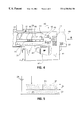
- FIG. 4 is a side view partially cut away showing apparatus for carrying out the anodizing process of FIG. 3;
- FIG. 5 is an illustration of a technique for immersion anodizing of a formed can body, the technique being suitable for use in the present invention.
- FIG. 6 is a flow diagram illustrating steps in a process of can body fabrication including steps for the production of a surface exhibiting a dichroic effect (these steps being shown as boxes having round corners).
- one such interference film structure 10 (a trilayer film) consists of a reflective metal base layer 11 , a dielectric spacer layer 12 and a semi-transparent metal overlayer 13 —a so-called metal-dielectric-metal (MDM) structure.
- MDM metal-dielectric-metal
- the light rays 15 , 16 reflecting off the top and base layers re-combine either constructively or destructively at each wavelength so that some colours, i.e. wavelength ranges, are enhanced while others are suppressed.
- the film can be strongly coloured if the top and base layer metals are judiciously chosen (type of metal and thickness). The actual colour seen is determined by the thickness of the dielectric spacer layer 12 , which is typically in the submicron range (i.e. less than 1 ⁇ m).
- Such a structure by itself, is not necessarily dichroic in appearance.
- Dichroic effects are realized in an MDM structure that is strongly coloured when, additionally, the index of refraction (n) of the dielectric layer is low and the thickness of the layer is within a prescribed range (normally 0.3 to 1 ⁇ m).
- the illustrated MDM structure is the simplest optical thin film structure, from the point of view of the number of layers involved, that is capable of generating strong colours and dramatic dichroic effects. More complicated structures, with additional metal/dielectric layers or based on all-dielectric multilayers, are known that can produce specific colours or colour shifts not accessible with the MDM structure. Examples of such structures are shown, for example, in U.S. Pat. No. 5,218,472. All of these structures are included within the scope of the present invention, although the simplest trilayer structure is the most preferred for simplicity and economy. The behaviour (colour and colour shifting properties) of such structures are readily modeled given known optical properties of the metals and dielectrics.
- dichroic structures of the present invention may be made by vacuum deposition methods, such as sputtering and evaporation, and such methods of fabrication may be employed in the present invention; however, this is not preferred. It is most preferable that the dichroic structures of the present invention be made by a combination of anodization and electroless metal plating techniques. In this way, the process for the production of the dichroic structure may be incorporated into conventional commercial can production, washing and surface treatment processes, which is a significant and unexpected advantage.
- the anodization to form the dichroic spacer layer 12 may take the form of spray anodizing or immersion anodizing.
- FIG. 2 illustrates the basic concept of spray anodizing in which an electrically conductive nozzle 20 sprays a stream of conductive electrolyte solution 21 onto a surface 22 to be anodized of a metal substrate 23 .
- the nozzle 20 is connected as a cathode to a voltage generation device 24 (e.g a battery or DC transformer), and the metal substrate 23 is connected as an anode.
- Anodization of the surface 22 takes place only where the stream of electrolyte contacts the metal surface 22 , provided the stream 21 is unbroken between the nozzle 20 and the surface 22 and thus remains electrically conductive.
- the anodization normally requires a period of time in the range of 30 to 60 seconds when the substrate metal is aluminum and the dichroic layer is to be grown to a thickness suitable for the generation of a dichroic effect (typically 0.3 to 0.8 ⁇ m, which covers the range of most interesting colours and colour shifts).
- Suitable electrolytes and concentrations are known to persons skilled in the art, but preferably the electrolyte is an aqueous solution of sulfuric acid.
- the electrolyte used for the spray may, of course, be collected in a suitable reservoir and re-used, i.e. a pumping device (not shown) used to supply electrolyte under pressure to the spray nozzle may draw the electrolyte from the collection reservoir. Fresh electrolyte may be added as required to compensate for losses and to maintain the required concentrations of solutes.
- the outside surface of a newly ironed and washed can body may be spray anodized in the manner indicated in FIG. 3 .
- a can body 30 (only one is shown for simplicity, but there would of course be a procession of such can bodies in a commercial operation) is supported in an inverted (open end down) orientation between a moving metal support mesh conveyor 31 and a moving stabilizing mesh conveyor 32 , the latter providing pressure on the can body from the top, thus ensuring that the can body is firmly held in place between the two mesh conveyors that move in the direction of the arrows at the same speed through the anodizing apparatus.
- Electrically conductive nozzles 20 a, 20 b are arranged above the path of the can body, directed downwards at angles so that electrolyte sprays 21 a, 21 b contact the side surfaces of the can body in the manner shown. While only a pair of nozzles 20 a, 20 b is shown, more may be provided, as required, to surround the can body 30 and to ensure that the spray covers as much of the outer surface of the can body 30 as is desired.
- a voltage generation 24 is connected as illustrated to the lower metal support mesh conveyor 31 and to the nozzles 20 a, 20 b. The can body 30 thus becomes an anode and the nozzles become cathodes, permitting anodization to proceed.
- the inverted orientation of the can body 30 ensures that the insides of the can body are not anodized. If treatment of both the inside and the outside of the can body were desired, a second bank of spray nozzles (not shown) could be provided in an upward spraying configuration beneath the mesh conveyor 31 . While there would normally be no reason to provide a dichroic structure inside a can body (as the inside is rarely seen in use), such a bank of nozzles could be employed for electrolytic cleaning of the inside of the can body.
- FIG. 4 is a side view, partly cut away, of a spray treatment apparatus that may be used for a spray anodization step described above (or the spray electroless metal plating step described later) in this description.
- the apparatus 40 is supported by a chemical tank 41 acting as a reservoir for the electrolyte.
- the tank 41 incorporates a removable screen 42 for removing particles from the electrolyte as it is recycled.
- the tank also includes an overflow trough 43 for removal of excess electrolyte during operation of the apparatus.
- a spray chamber 44 contains a drain pan 45 at the lower end thereof for collecting spent electrolyte and returning it to the tank 41 .
- a moving metal support mesh conveyor 31 travels through the spray chamber 44 in the direction of arrow A (note that the direction of travel is opposite to that of FIG.
- a second stabilizing mesh conveyor 32 moves in parallel to fix can bodies 30 in place.
- the lower mesh conveyor 31 is connected to a circuit (not shown) to make the cans anodic.
- a series of spray risers 46 and nozzles 20 is provided in the spray chamber with the nozzles directed to spray jets of electrolyte downwards over the exterior surfaces of the inverted (open end down) can bodies 30 .
- the nozzles 20 are made of metal and are connected as cathodes in the electrolysis circuit.
- the electrolyte is fed under pressure to the nozzles 20 from the tank 41 via pump 47 .
- the pressure is monitored pressure gauge 48 and can be controlled by a flow regulating valve 49 .
- the temperature of the electrolyte in the tank 41 may also be monitored by a temperature gauge 50 .
- a blower tube 51 for air is provided to help the treated can bodies drain and dry.
- the used electrolyte is collected by drain pan 45 and returned to the tank 41 via removable screen 42 .
- the electrolyte collected in the tank 41 is then available for re-use upon being collected by pump 47 and re-directed under pressure to the nozzles 20 . In this way, the desired anodization can be carried out on a continuous basis as newly-produced can bodies emerge from conventional production and washing apparatus.
- the spray of electrolyte should contact the sidewalls of the can body as an un-interrupted stream and produce a continuous sheath of electrolyte over the can surface (or at least the part of the surface to be coloured). Also, the spray should be broken up into a distinct droplet stream by the time that it impinges on the lower mesh conveyor 31 in regions where a can body does not interrupt the stream; this prevents direct short-circuiting of the nozzle cathode to the anodic conveyor mesh.
- the illustrated apparatus is similar in many respects to known washing equipment and to known equipment used to electrophoretically coat the inside and outside of can bodies with lacquer as an alternative to the now conventional processes of spray coating (for the inside lacquer) and roller coating (for the outside lacquer).
- the electrophoretic deposition process is similar to anodizing, so similar equipment and techniques may be employed.
- the only essential difference in carrying out the two processes is that the electrolyte is a polymeric solution in the former case and an acid solution in the latter (along with different typical voltages and current densities used in the two processes).
- Typical apparatus and techniques are disclosed, for example, in British patent 1,604,035 and U.S. Pat. Nos. 4,400,251, 5,164,056 and 5,435,899; the disclosures of which are specifically incorporated herein by reference.
- FIG. 5 A simple illustration of how the anodizing might be implemented in the immersion mode is given in FIG. 5.
- a can body 30 (one of a procession) is again supported on a mesh conveyor 31 with an upper mesh conveyor 32 to hold the can body in place.
- the upper mesh conveyor 32 is arranged outside a reservoir of the electrolyte 21 and is biased anodically by the voltage generation device 24 .
- the majority of the can body (in the opening facing the top orientation) is immersed within the reservoir of the electrolyte.
- a mesh 33 underlying the supporting mesh conveyor 31 or, alternatively, a configuration of electrodes (not shown), immersed in the electrolyte serves as the fixed cathode. In this case, a space at the top of the can must be left uncoated so that the top mesh does not contact the electrolyte and short to the cathode directly through the electrolyte.
- immersion type electrophoretic deposition of lacquers is known, so that these may be used for the immersion anodization of the present invention.
- Known devices of this kind include turret-fed systems where individual can bodies are enclosed in a housing which is filled with electrolyte and then flushed clean for successive processing of individual can bodies.
- Such a system may be applicable to the MDM process of the present invention for small volume applications and if the anodizing step is separated from the subsequent electroless deposition step.
- this type of design is most appropriate for an electrolytic process lasting at most a few seconds as is the case for lacquer deposition; otherwise can body throughput is severely compromised by such a successive processing approach.
- processing of cans while they are being transported in massed flow is the preferred approach as described above.
- the semi-transparent metal layer is applied, preferably by electroless metal plating.
- electroless metal plating is well known in the art and is described, for example, in U.S. Pat. No. 5,218,472 referred to above.
- the can body is rinsed in water and then subjected to an electroless nickel plating technique. This follows the conventional three step process consisting of immersion in tin chloride (so called sensitization step), rinsing, immersion in palladium chloride (nucleation), rinsing, followed by immersion in Ni plating solution and final rinse.
- the residence time for the sensitization and nucleation steps is normally 30-60 seconds.
- the residence time for the Ni plating is typically 5 to 10 seconds.
- the thickness of Ni required is generally 5-10 nm, while the actual amounts of Sn and Pd deposited are well below an atomic monolayer. All of these steps can be accomplished by fully submerging the can in the successive reagents or by spraying the can successively with the reagents.
- the electroless deposition of the semi-transparent metal layer may be carried out by either a spray process or an immersion process, and both make possible very simple methods for patterning into coloured and un-coloured (metallic) areas. This is accomplished by omitting treatment in the not-to-be-coloured areas with any step of the Sn/Pd/Ni sequence. For spray coating, this can be achieved using directed sprays. Also, by varying the spray pattern in the anodizing stage, e.g. the actual spray fan pattern or angle of impingement, gradations in anodic film thickness over the can surface can be achieved that will lead to multicolour patterns when the surface is subsequently uniformly metallized. For example, heavier spray near the top of the can, by changing the angle of impingement, may yield a top-to-bottom colour variation. Using a spray pattern that is not uniform across the fan width may yield longitudinal streaks along the length of the sidewall.
- anodization and metal deposition steps of the present invention may be incorporated into conventional commercial processes for the production of can bodies, thus allowing substantial economy and ease of operation.
- can bodies are conventionally made from a coil of aluminum can body stock 60 .
- the first step 61 in the manufacturing process is to form a cup.
- cups are turned out by a high speed cupping press having up to 14 dies and operating at up to 250 strokes/min.
- Trackwork separates the cups into a number of single file streams which feed individual bodymakers that form the can bodies from the cups by drawing and ironing.
- each bodymaker can take cups at a rate of up to 250 cans/min so up to 14 of these are set up to handle the output of one cupper press.
- Cans are drawn to final diameter and then ironed to the final wall thickness, step 62 .
- the cans are transported through trackwork to a dedicated trimmer where they are trimmed to length, step 63 .
- the cans are discharged onto a mat-top conveyor on which they are able to drip and lose much of the lubricant with which they are coated.
- the can bodies are fed into a vacuum inverter which rotates them from an open-end-up orientation to an open-end-down orientation suitable for the wash stage.
- the can bodies are then transferred from the inverter to a horizontal air conveyor which serves to accumulate the cans as they are transported to the washer.
- An area providing a few minutes of accumulation may be provided so that the cupper and bodymakers can continue to work if the washer stops briefly.
- a solid pack of can bodies is presented to and handled in the washer which involves a multi-stage spray processing operation.
- the wash process is designed to thoroughly remove all contaminants from the drawn and ironed can body and to prepare the can body surface to receive interior and exterior organic coatings (in the conventional process).
- the types of contaminants that must be cleaned include residual rolling mill oil and smut, cupper and bodymaker lubricants, aluminum fines generated during the cup and can forming process and tramp (hydraulic) oils from forming equipment that leaks into the soluble oils system.
- Optional conventional surface treatment within the washer may consist of applying either a thin conversion coating, to promote adhesion of coatings, prevent dome staining during pasteurization of beer and to enhance corrosion resistance of the inside can surface, or applying a coating to enhance mobility of cans in the various can transport systems used in subsequent processing of the cans.
- the overall process typically comprises six steps: pre-washing 64 , cleaning 65 , rinsing 66 , treating 67 , rinsing 68 , rinse/de-mineralizing 69 , as illustrated in FIG. 6 .
- the pre-wash uses a dilute H 2 SO 4 /HF solution to remove the heavy accumulation of soluble oils on the can body's surface before entering the cleaning stage.
- Cleaning uses a H 2 SO 4 /HF/surfactant mix to remove aluminum fines, native oxide and rolling oils from both the interior and exterior of the cans. All chemicals used are typically obtained in optimized commercial formulations such as the RidoleneTM/AlodineTM cleaning/treating package from Amchem.
- the spray time is approximately 60 seconds at a pressure of 35 psi and temperature of 50° C.
- 20-30 mg of Al metal is removed per can body, and the can surface will be water-break-free after this stage. Failure to completely remove the organic soils (oils, lubricants) will result in incomplete or non-uniform conversion coating which will lead to adhesion problems.
- Over-etching the cans may result in cans having poor mobility or in difficulties at the decorating stage because the can surface is too rough. Under-etching may leave oxide and entrained rolling oil that can generate so-called bleed through defects after decorating.
- the third stage rinse stops the chemical etching and removes residual cleaning solutions and soils.
- the fourth stage can be used to apply a thin Zr-based chemical conversion coating (coating weight 20 mg/M 2 ).
- Spray time is 15-30 seconds at about 10 psi and a temperature of 32° C. Excessive treatment can result in poor can mobility or in interior metal exposure or ink adhesion loss since the conversion coating is brittle and can crack or flake off if too thick.
- the fifth stage rinse removes residual coating solution which otherwise would continue to react with the Al surface.
- the final stage 69 is a de-ionised water rinse that removes minerals such as calcium, silicates and phosphates from the can surface. Any minerals left on the can surface could affect adhesion of organic coatings or cause water spotting that may result in show-through on some labels.
- a dry-off oven (not shown) at the exit of the washer removes all water from the can surface.
- the process of the present invention can be incorporated at this stage of the conventional process.
- the anodizing step is carried out by spray anodizing with sulphuric acid corresponding to the stage 1 cleaning step with sulphuric acid in the normal wash process.
- the final bank of spray nozzles in this stage is used for rinsing.
- the sensitization step is carried out in stage 2 followed by the stage 3 rinse.
- Nucleation is carried out in stage 4 followed by the stage 5 rinse.
- the Pd deposition and final rinse are carried out with the spray banks in stage 6 .
- a can body carrying a uniform dichroic finish around the whole sidewall exterior may be produced by washing the as-drawn-and-ironed can in the indicated manner, anodizing 70 the can surface to produce an anodic film in the thickness range of 0.3-1.0 ⁇ m, rinsing 71 the anodized can body, and then metallizing the surface of the anodic film with a thin semi-transparent layer of metal 5-10 nm in thickness, by electroless deposition involving the steps of sensitization 72 , rinsing 73 , nucleation 74 , rinsing 75 , and metallization 76 , followed by a final rinse 77 .
- the final product 79 is a can body having a dichroic surface suitable for delivery to beverage manufacturers for filling and lidding to create finished beverage cans.
- the invention is based in part, at least in its preferred forms, on the unexpected realization that the number of process steps, the nature of these steps and the required residence times are similar to what is required in the normal can washing process.
- the entire process can thus be carried out in equipment and with throughputs consistent with the conventional can making operation.
- the anodizing is carried out in sulphuric acid electrolyte and the metallization layer is Ni.
- the metallization layer is Ni.
- MDM metal/dielectric/metal
- the invention recognizes and exploits the fact that the ironed aluminum can surface is highly reflective and can function as the base layer in an MDM structure to yield vibrant colours without the use of brighteners (this is not the case for steel, for example). Also the diameter of the conventional can is such that the resulting curvature yields an appealing variation in colour around the can surface when a dichroic structure is viewed, even without tilting the can. The flip-flop colour effect found when the can is actually tilted back and forth is an additional promotional feature.
- the resulting MDM surface can be subsequently printed and decorated in the conventional manner. Furthermore, patterning of the MDM coating is possible by a number of process variations as described below.
- the MOM films produced as indicated above are not fingerprint sensitive, i.e. do not show a colour change under fingerprints, unlike many conventional dichroic films.
- the anodizing parameters in general, are similar to those used for the production of porous anodic films when grown much thicker. Without wishing to be limited to a particular theory, this is attributed to a self-sealing action of the very thin anodic films. This may be due to the film sealing during the anodizing or the subsequent rinse or possibly to sealing taking place, via the normal hydrothermal sealing mechanism, in the elevated-temperature, water-based Ni deposition step.
- the film, as produced is different from many conventional films, and this characteristic may make subsequent sealing steps unnecessary, further reducing the cost of the overall process. It is expected, however, that the dichroic structure of the present invention will still benefit from being overcoated, after further decoration and printing (if any), with a polymeric overvarnish typical of conventional can body production.
- the dichroic interference can be combined with colour absorption to realize additional optical effects.
- the colour shift of the dichroic effect can be made very abrupt with angle (as opposed to continuously varying through a sequence of colours) by selectively absorbing the intermediate colours.
- a bright can body was cleaned in a conventional alkaline cleaner to remove soils from manual handling (this step is not needed when cans go directly from the conventional wash process to the MDM process).
- the can body was then anodized in an aqueous solution of 165 g/l H 2 SO 4 at 16 volts DC (15 amp/dm 2 ) and 20° C. for 30 seconds.
- the can was rinsed under flowing water for several seconds then immersed in an aqueous solution of 1 g/l SnCl 2 for 1 minute at room temperature.
- the can body was then immersed in water for 1 minute and then in an aqueous solution of 0.5 g/l PdCl 2 for 1 minute at room temperature.
- After rinse immersion for 1 minute the can body was immersed in a commercial electroless Ni formulation, supplied by Ample Chemical Products Ltd, for 7 seconds with the bath held at 86° C.
- the can body was finally rinsed and blown dry.
- the resulting can body was a bright red colour which changed to golden yellow as it was tilted through about 45 degrees.
- the can body was viewed standing upright on a table, it was red over the central region nearest the viewer and changed to golden yellow near the peripheries.
- a second can body was put through the same procedure but with an anodizing time of 45 seconds. This can body was blue and changed to apple-green on tilting. A number of other distinctive colours and colour shifts are available with anodizing times in the 30-90 second range.
Abstract
Description
Claims (20)
Priority Applications (1)
| Application Number | Priority Date | Filing Date | Title |
|---|---|---|---|
| US09/421,600 US6358566B1 (en) | 1998-10-22 | 1999-10-20 | Process for producing decorative beverage can bodies |
Applications Claiming Priority (2)
| Application Number | Priority Date | Filing Date | Title |
|---|---|---|---|
| US10552498P | 1998-10-22 | 1998-10-22 | |
| US09/421,600 US6358566B1 (en) | 1998-10-22 | 1999-10-20 | Process for producing decorative beverage can bodies |
Publications (1)
| Publication Number | Publication Date |
|---|---|
| US6358566B1 true US6358566B1 (en) | 2002-03-19 |
Family
ID=22306321
Family Applications (2)
| Application Number | Title | Priority Date | Filing Date |
|---|---|---|---|
| US09/421,600 Expired - Fee Related US6358566B1 (en) | 1998-10-22 | 1999-10-20 | Process for producing decorative beverage can bodies |
| US09/807,432 Expired - Fee Related US6495003B1 (en) | 1998-10-22 | 1999-10-20 | Apparatus for producing decorative beverage can bodies |
Family Applications After (1)
| Application Number | Title | Priority Date | Filing Date |
|---|---|---|---|
| US09/807,432 Expired - Fee Related US6495003B1 (en) | 1998-10-22 | 1999-10-20 | Apparatus for producing decorative beverage can bodies |
Country Status (10)
| Country | Link |
|---|---|
| US (2) | US6358566B1 (en) |
| EP (1) | EP1135547B1 (en) |
| JP (1) | JP2002528642A (en) |
| AT (1) | ATE231568T1 (en) |
| AU (1) | AU6454699A (en) |
| BR (1) | BR9914715A (en) |
| CA (1) | CA2347831A1 (en) |
| DE (1) | DE69905075T2 (en) |
| NO (1) | NO20011998L (en) |
| WO (1) | WO2000024951A2 (en) |
Cited By (3)
| Publication number | Priority date | Publication date | Assignee | Title |
|---|---|---|---|---|
| US20050205112A1 (en) * | 2004-03-17 | 2005-09-22 | Green Bobby R | Selective removal or application of a coating on a portion of a container |
| US20130248373A1 (en) * | 2012-03-22 | 2013-09-26 | Hon Hai Precision Industry Co., Ltd. | Method for anodizing and dyeing metallic article |
| US20170259989A1 (en) * | 2012-11-12 | 2017-09-14 | 2266170 Ontario Inc. | Beverage Capsule And Process And System For Making Same |
Families Citing this family (9)
| Publication number | Priority date | Publication date | Assignee | Title |
|---|---|---|---|---|
| AU6454699A (en) | 1998-10-22 | 2000-05-15 | Alcan International Limited | Decorative beverage can bodies |
| TWI302027B (en) * | 2006-03-17 | 2008-10-11 | Ind Tech Res Inst | A wafer level packaging structure with inductors and manufacture method thereof |
| US20080166482A1 (en) * | 2007-01-08 | 2008-07-10 | Frye Robert D | Decorated Aluminum Surfaces and Methods of Producing Decorated Aluminum Surfaces |
| CN101941356B (en) * | 2009-07-06 | 2012-12-26 | 厦门华侨电子股份有限公司 | Decorative body structure capable of realizing gradual change of color |
| ITPR20100047A1 (en) * | 2010-05-21 | 2011-11-22 | Massimiliano Gazzani | METHOD AND PLANT FOR ANODIZING AN ALUMINUM PROFILE OR ITS ALLOYS |
| RU2471895C1 (en) * | 2011-12-01 | 2013-01-10 | Федеральное государственное бюджетное образовательное учреждение высшего профессионального образования "Пензенский государственный университет" (ФГБОУ ВПО "Пензенский государственный университет") | Method for obtaining coatings on surfaces of blind holes of parts from aluminium alloys |
| CN104223620A (en) * | 2013-06-20 | 2014-12-24 | 中钞特种防伪科技有限公司 | Coin medal |
| JP2018085299A (en) * | 2016-11-25 | 2018-05-31 | 学校法人関東学院 | Planar heater |
| RU2694859C1 (en) * | 2018-10-05 | 2019-07-17 | Федеральное государственное бюджетное образовательное учреждение высшего образования "Пензенский государственный университет" (ФГБОУ ВО "Пензенский государственный университет") | Method of producing coatings on surfaces of deep through holes with straight and curved axes in articles from valve metal alloys |
Citations (11)
| Publication number | Priority date | Publication date | Assignee | Title |
|---|---|---|---|---|
| JPS53149415A (en) | 1977-05-27 | 1978-12-26 | Ibm | Cartridge for typewriter |
| GB1604035A (en) | 1978-05-31 | 1981-12-02 | Metal Box Co Ltd | Method and apparatus for electrolytically treating a container body |
| US4400251A (en) | 1981-06-05 | 1983-08-23 | Aluminum Company Of America | Method and apparatus for simultaneously electrocoating the interior and exterior of a metal container |
| WO1992019796A1 (en) | 1991-05-07 | 1992-11-12 | Alcan International Limited | Process for producing anodic films exhibiting coloured patterns and structures incoporating such films |
| WO1992019795A1 (en) | 1991-05-07 | 1992-11-12 | Alcan International Limited | Process for producing articles comprising anodized films exhibiting areas of different colour and the articles thus produced |
| US5164056A (en) | 1989-11-16 | 1992-11-17 | Plm Berlin Dosenwerk Gmbh | Apparatus and process for the anodic or cathodic electrocoating of hollow bodies, in particular of cans |
| US5202013A (en) * | 1991-10-15 | 1993-04-13 | Alcan International Limited | Process for coloring metal surfaces |
| US5218472A (en) * | 1989-03-22 | 1993-06-08 | Alcan International Limited | Optical interference structures incorporating porous films |
| WO1994008073A1 (en) | 1992-10-05 | 1994-04-14 | Alcan International Limited | Process for producing anodic films exhibiting coloured patterns and structures incorporating such films |
| US5435899A (en) | 1992-11-03 | 1995-07-25 | Pechiney Recherche | Method, device and apparatus for the surface treatment of metal can bodies, in particular of Al or alloys thereof |
| US5445680A (en) * | 1990-12-07 | 1995-08-29 | Golden Technologies Company, Inc. | Method of decorating metal surfaces |
Family Cites Families (5)
| Publication number | Priority date | Publication date | Assignee | Title |
|---|---|---|---|---|
| JPS5576070A (en) | 1978-12-01 | 1980-06-07 | Asahi Keikinzoku Kogyo Kk | Enameled aluminum vessel and manufacture thereof |
| GB8811982D0 (en) | 1988-05-20 | 1988-06-22 | Metal Box Plc | Apparatus for electrolytic treatment of articles |
| US5120410A (en) | 1990-09-17 | 1992-06-09 | Service Tool Die & Mfg. Company | Rotary electrocoating machine |
| US5120126A (en) * | 1991-06-14 | 1992-06-09 | Ball Corporation | System for non-contact colored label identification and inspection and method therefor |
| AU6454699A (en) | 1998-10-22 | 2000-05-15 | Alcan International Limited | Decorative beverage can bodies |
-
1999
- 1999-10-20 AU AU64546/99A patent/AU6454699A/en not_active Abandoned
- 1999-10-20 US US09/421,600 patent/US6358566B1/en not_active Expired - Fee Related
- 1999-10-20 US US09/807,432 patent/US6495003B1/en not_active Expired - Fee Related
- 1999-10-20 BR BR9914715-7A patent/BR9914715A/en not_active IP Right Cessation
- 1999-10-20 EP EP99952174A patent/EP1135547B1/en not_active Expired - Lifetime
- 1999-10-20 DE DE69905075T patent/DE69905075T2/en not_active Expired - Fee Related
- 1999-10-20 AT AT99952174T patent/ATE231568T1/en not_active IP Right Cessation
- 1999-10-20 CA CA002347831A patent/CA2347831A1/en not_active Abandoned
- 1999-10-20 JP JP2000578501A patent/JP2002528642A/en active Pending
- 1999-10-20 WO PCT/CA1999/000975 patent/WO2000024951A2/en active IP Right Grant
-
2001
- 2001-04-23 NO NO20011998A patent/NO20011998L/en not_active Application Discontinuation
Patent Citations (11)
| Publication number | Priority date | Publication date | Assignee | Title |
|---|---|---|---|---|
| JPS53149415A (en) | 1977-05-27 | 1978-12-26 | Ibm | Cartridge for typewriter |
| GB1604035A (en) | 1978-05-31 | 1981-12-02 | Metal Box Co Ltd | Method and apparatus for electrolytically treating a container body |
| US4400251A (en) | 1981-06-05 | 1983-08-23 | Aluminum Company Of America | Method and apparatus for simultaneously electrocoating the interior and exterior of a metal container |
| US5218472A (en) * | 1989-03-22 | 1993-06-08 | Alcan International Limited | Optical interference structures incorporating porous films |
| US5164056A (en) | 1989-11-16 | 1992-11-17 | Plm Berlin Dosenwerk Gmbh | Apparatus and process for the anodic or cathodic electrocoating of hollow bodies, in particular of cans |
| US5445680A (en) * | 1990-12-07 | 1995-08-29 | Golden Technologies Company, Inc. | Method of decorating metal surfaces |
| WO1992019796A1 (en) | 1991-05-07 | 1992-11-12 | Alcan International Limited | Process for producing anodic films exhibiting coloured patterns and structures incoporating such films |
| WO1992019795A1 (en) | 1991-05-07 | 1992-11-12 | Alcan International Limited | Process for producing articles comprising anodized films exhibiting areas of different colour and the articles thus produced |
| US5202013A (en) * | 1991-10-15 | 1993-04-13 | Alcan International Limited | Process for coloring metal surfaces |
| WO1994008073A1 (en) | 1992-10-05 | 1994-04-14 | Alcan International Limited | Process for producing anodic films exhibiting coloured patterns and structures incorporating such films |
| US5435899A (en) | 1992-11-03 | 1995-07-25 | Pechiney Recherche | Method, device and apparatus for the surface treatment of metal can bodies, in particular of Al or alloys thereof |
Cited By (5)
| Publication number | Priority date | Publication date | Assignee | Title |
|---|---|---|---|---|
| US20050205112A1 (en) * | 2004-03-17 | 2005-09-22 | Green Bobby R | Selective removal or application of a coating on a portion of a container |
| US7412979B2 (en) | 2004-03-17 | 2008-08-19 | Ball Corporation | Selective removal or application of a coating on a portion of a container |
| US20130248373A1 (en) * | 2012-03-22 | 2013-09-26 | Hon Hai Precision Industry Co., Ltd. | Method for anodizing and dyeing metallic article |
| US9458547B2 (en) * | 2012-03-22 | 2016-10-04 | Fu Tai Hua Industry (Shenzhen) Co., Ltd. | Method for anodizing and dyeing metallic article |
| US20170259989A1 (en) * | 2012-11-12 | 2017-09-14 | 2266170 Ontario Inc. | Beverage Capsule And Process And System For Making Same |
Also Published As
| Publication number | Publication date |
|---|---|
| DE69905075T2 (en) | 2009-04-02 |
| JP2002528642A (en) | 2002-09-03 |
| US6495003B1 (en) | 2002-12-17 |
| DE69905075D1 (en) | 2003-02-27 |
| NO20011998D0 (en) | 2001-04-23 |
| AU6454699A (en) | 2000-05-15 |
| NO20011998L (en) | 2001-06-22 |
| EP1135547B1 (en) | 2003-01-22 |
| WO2000024951A2 (en) | 2000-05-04 |
| BR9914715A (en) | 2001-08-07 |
| WO2000024951A3 (en) | 2000-08-10 |
| CA2347831A1 (en) | 2000-05-04 |
| ATE231568T1 (en) | 2003-02-15 |
| EP1135547A2 (en) | 2001-09-26 |
Similar Documents
| Publication | Publication Date | Title |
|---|---|---|
| US6358566B1 (en) | Process for producing decorative beverage can bodies | |
| EP1590507B1 (en) | Color finishing method | |
| JP5453630B2 (en) | Dyeing method for aluminum member, method for producing aluminum member, and aluminum member | |
| US20120103819A1 (en) | Aluminum article and process for making same | |
| US4861441A (en) | Method of making a black surface treated steel sheet | |
| CN101845656B (en) | Surface treatment process for high-gloss aluminum alloy drawing profiles | |
| EP1451393B1 (en) | Method of manufacturing anodised cosmetic cases with contrasting bright and textured surfaces | |
| CN107109652B (en) | Method for mirror coating an optical article | |
| CN107268050A (en) | A kind of method of the nickel plating on aluminium and aluminum alloy coiled materials | |
| TWI443226B (en) | Copper foil with resistive film | |
| US3939046A (en) | Method of electroforming on a metal substrate | |
| CN107299347A (en) | A kind of process of surface treatment of door and window aluminium alloy extrusions | |
| CN102061472A (en) | Surface oxidizing and film coating method for mirror finish aluminum | |
| CN206502880U (en) | A kind of high light anode process for producing line of aluminium sheet mobile phone shell | |
| KR20100101881A (en) | Electrodeposition coating system | |
| JPH06212494A (en) | Pretreating and electrodeposition coating device | |
| KR100266454B1 (en) | A method for coloring nonferrous metal using ti-plating | |
| JPH10166083A (en) | Manufacture of di can body | |
| CN115821261B (en) | Surface modification and color change methods and articles | |
| JP3330729B2 (en) | Method for producing multilayer plated steel sheet and method for producing heat diffusion type alloy plated steel sheet using multilayer plated steel sheet | |
| JP2001521581A (en) | Method for plating continuous product made of metal or nonmetal and apparatus used for this method | |
| CN112575356A (en) | Bonding wire removing method | |
| JPS6059298B2 (en) | Melt plating method for metal wire | |
| JPH08311685A (en) | Tin-plated steel sheet excellent in adhessiveness to coating material | |
| JPH07173673A (en) | Production of tin electroplated steel sheet |
Legal Events
| Date | Code | Title | Description |
|---|---|---|---|
| AS | Assignment |
Owner name: ALCAN INTERNATIONAL LIMITED, CANADA Free format text: ASSIGNMENT OF ASSIGNORS INTEREST;ASSIGNOR:ROSENFELD, ARON MARCUS;REEL/FRAME:010399/0308 Effective date: 19991112 |
|
| AS | Assignment |
Owner name: CITICORP NORTH AMERICA, INC., NEW YORK Free format text: SECURITY INTEREST;ASSIGNORS:NOVELIS CORPORATION;NOVELIS INC.;REEL/FRAME:016369/0282 Effective date: 20050107 Owner name: CITICORP NORTH AMERICA, INC.,NEW YORK Free format text: SECURITY INTEREST;ASSIGNORS:NOVELIS CORPORATION;NOVELIS INC.;REEL/FRAME:016369/0282 Effective date: 20050107 |
|
| REMI | Maintenance fee reminder mailed | ||
| LAPS | Lapse for failure to pay maintenance fees | ||
| STCH | Information on status: patent discontinuation |
Free format text: PATENT EXPIRED DUE TO NONPAYMENT OF MAINTENANCE FEES UNDER 37 CFR 1.362 |
|
| FP | Lapsed due to failure to pay maintenance fee |
Effective date: 20060319 |
|
| AS | Assignment |
Owner name: NOVELIS CORPORATION, OHIO Free format text: RELEASE BY SECURED PARTY;ASSIGNOR:CITICORP NORTH AMERICA, INC.;REEL/FRAME:020487/0294 Effective date: 20080207 Owner name: NOVELIS INC., GEORGIA Free format text: RELEASE BY SECURED PARTY;ASSIGNOR:CITICORP NORTH AMERICA, INC.;REEL/FRAME:020487/0294 Effective date: 20080207 Owner name: NOVELIS CORPORATION,OHIO Free format text: RELEASE BY SECURED PARTY;ASSIGNOR:CITICORP NORTH AMERICA, INC.;REEL/FRAME:020487/0294 Effective date: 20080207 Owner name: NOVELIS INC.,GEORGIA Free format text: RELEASE BY SECURED PARTY;ASSIGNOR:CITICORP NORTH AMERICA, INC.;REEL/FRAME:020487/0294 Effective date: 20080207 |