US6388765B1 - Page alignment indication method, page control method, printer system and printer device - Google Patents
Page alignment indication method, page control method, printer system and printer device Download PDFInfo
- Publication number
- US6388765B1 US6388765B1 US09/042,844 US4284498A US6388765B1 US 6388765 B1 US6388765 B1 US 6388765B1 US 4284498 A US4284498 A US 4284498A US 6388765 B1 US6388765 B1 US 6388765B1
- Authority
- US
- United States
- Prior art keywords
- data
- page
- printer
- unit
- print process
- Prior art date
- Legal status (The legal status is an assumption and is not a legal conclusion. Google has not performed a legal analysis and makes no representation as to the accuracy of the status listed.)
- Expired - Fee Related
Links
Images


Classifications
-
- G—PHYSICS
- G06—COMPUTING; CALCULATING OR COUNTING
- G06K—GRAPHICAL DATA READING; PRESENTATION OF DATA; RECORD CARRIERS; HANDLING RECORD CARRIERS
- G06K15/00—Arrangements for producing a permanent visual presentation of the output data, e.g. computer output printers
-
- G—PHYSICS
- G06—COMPUTING; CALCULATING OR COUNTING
- G06K—GRAPHICAL DATA READING; PRESENTATION OF DATA; RECORD CARRIERS; HANDLING RECORD CARRIERS
- G06K15/00—Arrangements for producing a permanent visual presentation of the output data, e.g. computer output printers
- G06K15/02—Arrangements for producing a permanent visual presentation of the output data, e.g. computer output printers using printers
- G06K15/18—Conditioning data for presenting it to the physical printing elements
- G06K15/1801—Input data handling means
- G06K15/1822—Analysing the received data before processing
-
- G—PHYSICS
- G06—COMPUTING; CALCULATING OR COUNTING
- G06K—GRAPHICAL DATA READING; PRESENTATION OF DATA; RECORD CARRIERS; HANDLING RECORD CARRIERS
- G06K2215/00—Arrangements for producing a permanent visual presentation of the output data
- G06K2215/0082—Architecture adapted for a particular function
- G06K2215/0085—Error recovery
Definitions
- the present invention relates to a page alignment indication method and page control method in transferring the data from a data creation device to a printer device and printing, along with the printer system and printer device utilizing said page executive method.
- the printer systems are used in which a plurality of personal computers and a printer are connected by communication lines such as LAN, and the data obtained by the personal computers as the data creation device are transferred to the printer and printed.
- page alignment process process to renew page in corrective manner in printing
- recovery process process to carry out reinstatement and recovery of the data when any abnormality in printing has occurred
- page control it is necessary to carry out page control over the data transferred from the personal computer (data creation device).
- a page alignment code to be incorporated in the transfer data is utilized. Concretely, the page alignment code “OC” which shows a page break is added to the last part of the data for one page.
- An object of the present invention is to provide a page alignment indication method which can recognize the page alignment in a short time without carrying out data analysis.
- Another object of the present invention is to provide a page control method with which the page control can be carried out quite quickly.
- a further object of the present invention is to provide a printer system and a printer device with which recovery process can be performed quickly and correctly.
- a page alignment code (unique code) comprising a sequence of a predetermined number or more of identical data of one or more bytes is inserted, and on the printer device side, the unique code is detected independently from the ordinary data analysis.
- the unique code in the present invention shows the constitution in which one or plural bytes of identical data are arranged in sequence, the unique code can be easily detected without executing the data analysis as hitherto, and the page alignment command from the data creation device can be recognized in a short time.
- control of the print control including the recovery process for each page is carried out according to the page alignment command thus recognized. Consequently, it is possible to carry out the control of this kind at a higher speed.
- FIG. 1 is a block diagram of a printer system according to the present invention
- FIG. 2 is a view to show an example of insertion of a unique code in the present invention
- FIG. 3 is a block diagram showing the constitution of the first embodiment
- FIG. 4 is a flow chart showing the procedure for the operation of the first embodiment
- FIG. 5 is a block diagram showing the constitution of the second embodiment
- FIGS. 6A and 6B are flow charts showing the procedure for the operation of the second embodiment
- FIG. 7 is a view schematically showing the recovery function from occurrence of paper jam in the second embodiment
- FIG. 8 is a block diagram showing the constitution of the third embodiment.
- FIG. 9 is a flow chart showing the procedure for the operation of the third embodiment.
- FIG. 10 is a block diagram showing the constitution of the fourth embodiment.
- FIG. 11 is a flow chart showing the procedure for the operation of the fourth embodiment.
- FIG. 1 is a block diagram of the printer system according to the present invention.
- the reference numeral 1 is for example LAN which is disposed in an office such as business office or business station.
- LAN 1 is connected with personal computers 2 as a data creation device for creating image data, a printer device 3 for printing the image data prepared by each personal computer 2 , and a PC server 4 for providing information to each personal computer 2 .
- the personal computer 2 prepares the data on the display as the image data according to the user's input. When it recognizes the page alignment, it inserts the page alignment code, i.e., unique code to show the break of the page, into the position after the image data and before the page alignment code which is similar to that described in the above.
- the page alignment code i.e., unique code to show the break of the page
- FIG. 2 is a view to show an example of insertion of the unique code as above, wherein, following the image data I which shows the data for one page portion, a unique code A formed by sequencing more than the predetermined number of bytes (about several thousand bytes) of data “ff” is inserted. After the unique code A, a page alignment code “ 0 c” similar to the conventional one is provided.
- the unique code A is constituted by continuing a predetermined number or more of the same kind of data comprising one or plural bytes. For the same kinds of data, optional kind ones (e.g., “10”, “234”, “a”, etc.) may be used. The code of the kind which can never occur in the printer system used should be employed for the purpose.
- the image data to which said unique code has been added is transmitted to the printer device 3 from each personal computer 2 and printed out to the hard copy. And, with the printer device 3 , the added unique code is detected, and according to the detection, the page alignment is executed. Based on the executed page alignment information, printing for each page and recovery process are carried out.
- FIG. 3 is a block diagram showing the constitution of the first embodiment.
- the personal computer 2 as a data creation device comprises an image data creation unit 21 for creating the image data based on the user's input operation, a unique code addition unit 22 for recognizing the page alignment and adding the unique code, an image memory 23 for storing the image data to which the unique code is added, and a control unit 24 for controlling the operation of the respective piece of hardware and controlling the recovery functions on the data creative device side.
- the data is sent from the unique code addition unit 22 to the printer device 3 , and in the case where the recovery function is fulfilled, the data is sent from the image memory 23 to the printer device 3 .
- the printer device 3 connected with the personal computer 2 by LAN 1 comprises a communication unit 31 for transferring the data from the personal computer 2 , a unique code detection unit 32 for detecting the unique code which is included in the transfer data, and a print process unit 33 for analyzing the transfer data and printing the image data.
- the communication unit 31 has a data transfer unit 34 for transferring the data from the personal computer 2 to the print process unit 33 , a page alignment executive unit 35 for carrying out the page alignment based on the detection result of the unique code detection unit 32 , and a page counter 36 which is counted up on each page alignment.
- the print process unit 33 has a data analysis unit 41 for analyzing the transmitted data, and a print execution unit 42 for carrying out printing according to the analysis result of the data analysis unit 41 .
- the data is transferred from the data transfer unit 34 to the print process unit 33 through the unique code detection unit 32 .
- the unique code detection unit 32 when detecting the unique code from the transferred data, notify the page alignment executive unit 35 of the detection.
- the page alignment executive unit 35 on receipt of the notice, transfers the page alignment code to the print process unit 33 .
- the data analysis unit 41 analyzes the transmitted data, and the print executive unit 42 prints out the data according to the analysis result.
- the print executive unit 42 sends to the page alignment executive unit 35 a print end notice at the point of completion, or, in case of the failure in completion of printing due to paper jam or the like, a print no end notice is sent at the point of the recognition of the failure.
- the page alignment executive unit 35 on receipt of the print end notice, increases the count value of the page counter 36 and notify the control unit 24 of the personal computer 2 of the completion of printing, while on receipt of the print no end notice, notify the control unit 24 of the personal computer 2 of the non-completion of printing.
- the count value of the page counter 36 is also sent to the control unit 24 .
- FIG. 4 is a flow chart showing the processing procedures of the first embodiment.
- the data prepared in the image data creative unit 21 is analyzed in the unique code addition unit 22 (Step S 1 ) to judge whether the page break has been recognized or not (Step S 2 ).
- Step S 1 the page break having been recognized
- Step S 2 YES
- a unique code formed by sequencing “ff” as shown in FIG. 2 by the predetermined number of bytes is added to the image data (Step S 3 ).
- Step S 4 the data is transferred to the communication unit 31 (data transfer unit 34 ) through the LAN 1 (Step S 4 ).
- the data is sent from the data transfer unit 34 to the print process unit 33 (data analysis unit 41 ) through the unique code detection unit 32 (Step S 5 ). And, in the course of the transfer, judgment is made whether the unique code is detected or not by the unique code detection unit 32 (Step S 6 ).
- the unique code detection unit 32 detects only presence or absence of the unique code without carrying out the image data analysis. That is to say, recognition of “ff” only is made, so that, when “ff” is recognized, the internal counter is counted up, while if no ff is detected, a processing to clear the counter is carried out, by which it is assumed that the unique code is detected at the time when the count value comes to the predetermined amount. In this manner, as it suffices to give attention to “ff” only, the unique code can be detected quite quickly.
- the page alignment executive unit 35 In the case of detecting the unique code (S 6 : YES), the page alignment executive unit 35 is notified to the effect that the detection has been made (Step S 7 ). In response to this notification, the page alignment code is transferred to the print process unit 33 (Step S 8 ).
- the data sent to the data analysis unit 41 is analyzed, and print process is carried out in the print executive unit 42 (Step S 9 ). And, judgment is made as to whether the print end notice has been sent from the print process unit 33 (print executive unit 42 ) to the page alignment executive unit 35 or not (Step S 10 ).
- the notice being sent namely, when the printing has normally ended (S 10 : YES)
- the count value of the page counter 36 is increased by one (Step S 11 )
- the end of printing is notified to the control unit 24 of the personal computer 2 from the page alignment executive unit 35 , and the count value at that time is notified to the control unit 24 from the page counter 36 (Step S 12 ). Consequently, it is possible to confirm on the side of the personal computer 2 which is a data creative device that the printing for one page has normally completed.
- the print end notice is not sent from the print process unit 33 (print execution unit 42 ) to the page alignment executive unit 35 , in other words, when the trouble such as paper jam, out of paper, etc. has occurred and the print no end notice has been received without completing printing (S 10 : NO), the print no end is notified from the page alignment executive unit 35 to the control unit 24 of the personal computer 2 , and the count value at that time is notified from the page counter 36 to the control unit 24 (Step S 13 ). And, the control unit 24 reads out the data of the page corresponding to the count value from the image memory 23 and retransfer the data to the data transfer unit 34 (Step S 14 ). The retransferred data is sent to the print process unit 33 through the unique code detection unit 32 and subjected to print process again (Step S 15 ). In the above manner, the recovery function is executed.
- the first embodiment is designed to perform a recovery function on the data creation device (personal computer 2 ) side.
- the memory for storing the transfer data on the printer device 3 side it is possible to fulfill the recovery function on the printer device 3 side.
- Such second embodiment is explained below.
- FIG. 5 is a block diagram showing the constitution of the second embodiment.
- the personal computer 2 as the data creation device comprises an image data creation unit 21 , a unique code addition unit 22 and an image memory 23 similar to those of the first embodiment, and a control unit 24 for controlling the operation of these respective piece of hardware.
- a unique code is added to the image data by the unique code addition unit 22 and sent to the printer device 3 .
- the printer device 3 connected with the personal computer 2 by the LAN 1 comprises a communication unit 31 , a unique code detection unit 32 , and a print process unit 33 , which are similar to those of the first embodiment.
- the communication unit 31 has a data transfer unit 34 for transferring the data from the personal computer 2 to the print process unit 33 , a page alignment executive unit 35 for carrying out the page alignment based on the detection result of the unique code detection unit 32 , a page counter 36 which is counted up on each page break, and a page memory 37 for storing the data of one page portion sent from the personal computer 2 .
- the data for one page portion sent from the personal computer 2 is written in the page memory 37 through the data transfer unit 34 , and stored in the page memory 37 until the printing of said transmitted data is completed.
- the data is transferred from the data transfer unit 34 to the print process unit 33 through the unique code detection unit 32 , and when the recovery function is executed, the data read out from the page memory 37 to the data transfer unit 34 is sent direct to the print process unit 33 through the unique code detection unit 32 .
- the unique code detection unit 32 when detecting the unique code from the transferred data, notifies the page alignment executive unit 35 of the detection.
- the page alignment executive unit 35 on receipt of the notice, transfers the page alignment code to the print process unit 33 .
- the print process unit 33 gives the print end notice when the printing for one page portion has been completed without trouble, or the print no end notice when the printing cannot be completed due to the cause such as paper jam, at the time of recognizing it, to the page alignment executive unit 35 .
- the page alignment executive unit 35 on receipt of the print end notice, causes to increase the count value of the page counter 36 , and notifies the control unit 24 of the personal computer 2 and the data transfer unit 34 of the print end, while on receipt of the print no end notice, notifies the data transfer unit 34 of the print no end.
- the data transfer unit 34 on receipt of the print end notice, erases the contents stored in the page memory 37 , and on receipt of the print no end notice, reads out the contents stored in the page memory 37 and transfers them to the print process unit 33 .
- the count value of the page counter 36 is sent to the control unit 24 .
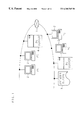
- FIGS. 6A and 6B are flow charts showing the processing procedures of the second embodiment.
- the data created in the image data creation unit 21 is analyzed in the unique code addition unit 22 (Step S 21 ) to judge whether the page alignment has been recognized or not (Step S 22 ).
- a unique code made by sequencing the predetermined number of bytes of “ff” as shown in FIG. 2 are added to the image data (Step S 23 ).
- the data is transferred to the data communication unit 31 (data transfer unit 34 ) through the LAN 1 (Step S 24 ).
- the data transferred to the data transfer unit 34 is stored in the page memory 37 (Step S 25 ).
- the transferred data is sent from the data transfer unit 34 to the print process unit 33 (data analysis unit 41 ) through the unique code detection unit 32 (Step S 26 ). And, in the course of the transfer, judgment is made by the unique code detection unit 32 whether the unique code has been detected or not (Step S 27 ).
- the unique code detection unit 32 detects the unique code by the process similar to that of the first embodiment. In case of the detection of the unique code (S 27 : YES), a report of detection is notified to the page alignment executive unit 35 (Step S 28 ). According to this notice, the page alignment code is transferred to the print process unit 33 (Step S 29 ).
- the data sent to the data analysis unit 41 is analyzed and print process is carried out by the print execution unit 42 (Step S 30 ). And, judgment is made as to whether the print end notice has been sent from the print process unit 33 (print execution unit 42 ) to the page alignment executive unit 35 or not (Step S 31 ).
- the notice has been sent namely, in the case of the normal completion of the printing (S 31 : YES)
- print end is notified from the page alignment executive unit 35 to the data transfer unit 34 (Step S 32 )
- the count value of the page counter 36 is increased by one (Step S 33 )
- the data stored in the page memory 37 is erased (Step S 34 ).
- the print end is notified from the page alignment executive unit 35 to the control unit 24 of the personal computer 2 , and the count value at that time is notified from the page counter 36 to the control unit 24 (Step S 35 ).
- FIG. 7 is a view which schematically shows such recovery function accompanied with paper jam.
- the data communication line is provided with a unique code detection unit 32 so as to have the page break recognized in the process of data communication, but it is also possible to constitute the apparatus so as to detect the unique code at the time of the actual image data analysis. Examples of such constitution are explained in the following third and fourth embodiments.
- FIG. 8 is a block diagram showing the constitution of the third embodiment.
- the personal computer 2 as the data creation device comprises an image data creation unit 21 , a unique code addition unit 22 , an image memory 23 and a control unit 24 similar to those of the first embodiment.
- the data is sent from the unique code addition unit 22 is sent to the printer device 3 , and when recovery function is fulfilled, the data is sent to the printer device 3 from the image memory 23 .
- the printer device 3 connected with the personal computer 2 by LAN 1 comprises a communication unit 31 for transferring the data from the personal computer 2 and a print process unit 33 which is to carry out analysis of the transferred data and print the image data.
- the communication unit 31 has a data transfer unit 34 for transferring the data from the personal computer 2 to the print process unit 33 .
- the print process unit 33 has a data analysis unit 41 for analyzing the transmitted data, a print execution unit 42 for carrying out printing according to the result of analysis by the data analysis unit 41 , and a page counter 43 which is counted up at each end of the printing of the data for each page.
- the data analysis unit 41 includes a unique code detection unit 44 which detects the unique code contained in the transferred data independently from the data analysis.
- the data from the personal computer 2 is transferred to the print process unit 33 (data analysis unit 41 ) through the communication unit 31 (data transfer unit 34 ).
- the unique code detection unit 44 detects the unique code from the transferred data, independently from the data analysis which is carried out in the data analysis unit 41 .
- the print execution unit 42 performs printing operation according to the analysis result in the data analysis unit 41 .
- the print execution unit 42 transmits the print end notice at the end point when the printing process has ended without trouble, or the print no end notice when the printing cannot be ended due to the paper jam or the like, at the time of recognizing it, to the data analysis unit 41 and the control unit 24 of the personal computer 2 , respectively.
- the page counter 43 is counted up.
- the count value of the page counter 43 is also sent to the control unit 24 .
- FIG. 9 is a flow chart showing the processing procedure of the third embodiment.
- the data created in the image data creation unit 21 is analyzed by the unique code addition unit 22 (Step S 41 ) and judgment is made as to whether it has recognized the page alignment or not (Step S 42 ).
- the unique code is added to the image data (Step S 43 ).
- the data is transferred to the print process unit 33 (data analysis unit 41 ) through the LAN 1 and communication unit 31 (data transfer unit 34 ) (Step S 44 ).
- the print process is carried out in the print execution unit 42 (Step S 46 ).
- Step S 47 Judgment is made as to whether the printing process in the print execution unit 42 has normally been completed or not.
- the print end notice is transmitted to the data analysis unit 41 and control unit 24 (Step S 48 ), the count value of the page counter 43 is counted up by one (Step S 49 ), and the count value is sent to the control unit 24 (Step S 50 ). Consequently, it can be confirmed on the personal computer 2 side which is a data creation unit that the printing for one page has normally completed.
- Step S 47 when trouble such as paper jam or out of paper occurs and print is not ended (S 47 : NO), the print no end notice is transmitted to the data analysis unit 41 and the control unit 24 , and the count value of the page counter 43 is sent to the control unit 24 (Step S 51 ). And, the control unit 24 reads out the data on the page corresponding to the count value from the image memory 23 . The read out data is sent again to the print process unit 33 (data analysis unit 41 ) through the data transfer unit 34 (Step S 52 ). The analysis process to the resent data is carried out in the data analysis unit 41 , and the print process is carried out again (Step S 53 ). In the above manner, the recovery function is executed.
- the recovery function is performed on the data creative unit (personal computer 2 ) side.
- the recovery function is performed on the data creative unit (personal computer 2 ) side.
- a memory for storing the transferred data on the side of the printer device 3 , it becomes possible to perform a recovery function on the printer device 3 side.
- Such fourth embodiment is shown below.
- FIG. 10 is a block diagram showing the constitution of the fourth embodiment.
- the personal computer 2 as a data creative device comprises an image data creation unit 21 , a unique code addition unit 22 , an image memory 23 and a control unit 24 for controlling these hardware operations, similar to those of the third embodiment.
- a unique code is added to the image data by the unique code addition unit 22 and the image data is sent to the printer device 3 .
- the printer device 3 connected with the personal computer 2 by LAN 1 comprises a communication unit 31 and a print process unit 33 similar to those of the third embodiment.
- the print process unit 33 has a data analysis unit 41 for analyzing the transmitted data, a print execution unit 42 for carrying out printing according to the result of analysis by the data analysis unit 41 , a page counter 43 which is counted up at each end of the printing of the data for each page, and a page memory 45 for storing the transmitted data for one page portion from the personal computer 2 .
- the data analysis unit 41 includes a unique code detection unit 44 which detects the unique code contained in the transferred data independently from the data analysis.
- the data for one page portion transmitted from the personal computer 2 (unique code addition unit 22 ) is written in the page memory 45 through the data transfer unit 34 and data analysis unit 41 , and stored in the page memory 45 until the printing of the transmission data is over.
- the data is transferred to the print process unit 33 (data analysis unit 41 ) from the personal computer 2 through the data transfer unit 34 , and in the case of performing the recovery function, the data is read out from the page memory 45 to the data analysis unit 41 .
- the unique code detection unit 44 detects the unique code from the transferred data, independently from the data analysis which is carried out in the data analysis unit 41 .
- the print execution unit 42 performs printing operation according to the result of analysis at the data analysis unit 41 .
- the print execution unit 42 transmits the print end notice to the data analysis unit 41 and the control unit 24 of the personal computer 2 .
- the page counter 43 is counted up.
- the count value of the page counter 43 is also sent to the control unit 24 .
- the print no end notice is transmitted to the data analysis unit 41 at the point of recognizing the failure.
- the data analysis unit 41 on receipt of the print no end notice, reads out the stored contents of the page memory 45 and again carries out the data analysis, and transfers the analysis results to the print execution unit 42 . And, the print execution unit 42 performs the printing operation again.
- FIG. 11 is a flow chart showing the processing procedure of the fourth embodiment.
- the data created in the image data creative unit 21 is analyzed in the unique code addition unit 22 (Step S 61 ) and judgment is made as to whether the page alignment has been recognized or not (Step S 62 ).
- the unique code is added to the image data (Step S 63 ).
- the data is transferred to the print process unit 33 (data analysis unit 41 ) through the LAN 1 and the communication unit 31 (data transfer unit 34 ) (Step S 64 ).
- the data transferred to the data analysis unit 41 is stored in the page memory 45 (Step S 65 ). And, in the unique code detection unit 44 , independently from the image data analysis process, in the same procedure as the first embodiment, when the unique code is detected (Step S 66 : YES), according to the analysis result of the image data in the data analysis unit 41 , the print process is executed in the print execution unit 42 (Step S 67 ).
- Step S 68 Judgment is made as to whether the print process in the print execution unit 42 is normally ended or not.
- the print end notice is transmitted to the data analysis unit 41 and control unit 24 (Step S 69 ), the data stored in the page memory 45 is canceled (Step S 70 ), and further, the count value of the page counter 43 is increased by one (Step S 71 ), and the count value is sent to the control unit 24 (Step S 72 ). Consequently, it can be confirmed on the personal computer 2 side which is a data creative device that the printing of one page portion has normally been completed.
- Step S 68 when the printing is not completed due to the occurrence of trouble such as paper jam, out of paper, etc. (S 68 : NO), a print no end notice is transmitted to the data analysis unit 41 (Step S 73 ). And, the data stored in the page memory 45 is read out to the data analysis unit 41 (Step S 74 ). The read out data is analyzed by the data analysis unit 41 , and the analysis result is sent to the print execution unit 42 and print processing is executed again (Step S 75 ). In the manner as described above, the recovery function is executed on the printer 3 side.
- the unique code to show the page break can be detected, and as the data analysis is unnecessary, the page break can be recognized in a short time in comparison with the conventional system, thus contributing to improvement of the printer performance.
- the page alignment process and recovery process are performed on the basis of the unique code detection, there are effects that these processes can be made quickly.
Abstract
Description
Claims (18)
Applications Claiming Priority (2)
| Application Number | Priority Date | Filing Date | Title |
|---|---|---|---|
| JP9-232913 | 1997-08-28 | ||
| JP9232913A JPH1170712A (en) | 1997-08-28 | 1997-08-28 | Page feed designating method, page control method, printer system and printer |
Publications (1)
| Publication Number | Publication Date |
|---|---|
| US6388765B1 true US6388765B1 (en) | 2002-05-14 |
Family
ID=16946809
Family Applications (1)
| Application Number | Title | Priority Date | Filing Date |
|---|---|---|---|
| US09/042,844 Expired - Fee Related US6388765B1 (en) | 1997-08-28 | 1998-03-17 | Page alignment indication method, page control method, printer system and printer device |
Country Status (2)
| Country | Link |
|---|---|
| US (1) | US6388765B1 (en) |
| JP (1) | JPH1170712A (en) |
Cited By (9)
| Publication number | Priority date | Publication date | Assignee | Title |
|---|---|---|---|---|
| US20010015823A1 (en) * | 2000-02-22 | 2001-08-23 | Hiroyuki Sato | Image processing apparatus and control method therefor |
| US6491220B1 (en) * | 2000-11-01 | 2002-12-10 | International Business Machines Corporation | Resistive page counting for paper tablets |
| US20030053113A1 (en) * | 2001-09-14 | 2003-03-20 | Canon Kabushihki Kaisha | Method and apparatus for processing information |
| US20040068698A1 (en) * | 2002-10-04 | 2004-04-08 | Fuji Xerox Co., Ltd. | Image forming device and method |
| US20050097438A1 (en) * | 2003-09-24 | 2005-05-05 | Jacobson Mark D. | Method and system for creating a digital document altered in response to at least one event |
| US20070024902A1 (en) * | 2005-07-26 | 2007-02-01 | Brother Kogyo Kabushiki Kaisha | Printing device, system and method for image forming |
| US20080097837A1 (en) * | 2006-10-23 | 2008-04-24 | Format Dynamics, Llc | Method and system for printing information related to internet advertisements |
| US20080144100A1 (en) * | 2006-12-14 | 2008-06-19 | Seiko Epson Corporation | Printing control device and printing control method |
| US20110029859A1 (en) * | 2009-06-09 | 2011-02-03 | Canon Kabushiki Kaisha | Image processing apparatus, image processing method, and storage medium |
Citations (5)
| Publication number | Priority date | Publication date | Assignee | Title |
|---|---|---|---|---|
| JPS60124728A (en) * | 1983-12-12 | 1985-07-03 | Canon Inc | Character processing unit |
| JPH01229325A (en) * | 1988-03-09 | 1989-09-13 | Mitsubishi Electric Corp | Data processor |
| JPH03139719A (en) * | 1989-10-26 | 1991-06-13 | Nec Corp | Installation verification system for program |
| US5519867A (en) * | 1993-07-19 | 1996-05-21 | Taligent, Inc. | Object-oriented multitasking system |
| US5881064A (en) * | 1994-03-18 | 1999-03-09 | Samuel A. Kassatly | Packet-switched data network and method of operation |
-
1997
- 1997-08-28 JP JP9232913A patent/JPH1170712A/en active Pending
-
1998
- 1998-03-17 US US09/042,844 patent/US6388765B1/en not_active Expired - Fee Related
Patent Citations (5)
| Publication number | Priority date | Publication date | Assignee | Title |
|---|---|---|---|---|
| JPS60124728A (en) * | 1983-12-12 | 1985-07-03 | Canon Inc | Character processing unit |
| JPH01229325A (en) * | 1988-03-09 | 1989-09-13 | Mitsubishi Electric Corp | Data processor |
| JPH03139719A (en) * | 1989-10-26 | 1991-06-13 | Nec Corp | Installation verification system for program |
| US5519867A (en) * | 1993-07-19 | 1996-05-21 | Taligent, Inc. | Object-oriented multitasking system |
| US5881064A (en) * | 1994-03-18 | 1999-03-09 | Samuel A. Kassatly | Packet-switched data network and method of operation |
Cited By (21)
| Publication number | Priority date | Publication date | Assignee | Title |
|---|---|---|---|---|
| US7321445B2 (en) * | 2000-02-22 | 2008-01-22 | Canon Kabushiki Kaisha | Image processing apparatus and control method therefor |
| US20050280854A1 (en) * | 2000-02-22 | 2005-12-22 | Canon Kabushiki Kaisha | Image processing apparatus and control method therefor |
| US6982811B2 (en) * | 2000-02-22 | 2006-01-03 | Canon Kabushiki Kaisha | Image processing apparatus and control method therefor |
| US20010015823A1 (en) * | 2000-02-22 | 2001-08-23 | Hiroyuki Sato | Image processing apparatus and control method therefor |
| US6491220B1 (en) * | 2000-11-01 | 2002-12-10 | International Business Machines Corporation | Resistive page counting for paper tablets |
| US20030053113A1 (en) * | 2001-09-14 | 2003-03-20 | Canon Kabushihki Kaisha | Method and apparatus for processing information |
| US7145687B2 (en) * | 2001-09-14 | 2006-12-05 | Canon Kabushiki Kaisha | Method and apparatus for processing information |
| US7366981B2 (en) * | 2002-10-04 | 2008-04-29 | Fuji Xerox Co., Ltd. | Image forming device and method |
| US20040068698A1 (en) * | 2002-10-04 | 2004-04-08 | Fuji Xerox Co., Ltd. | Image forming device and method |
| US20050097438A1 (en) * | 2003-09-24 | 2005-05-05 | Jacobson Mark D. | Method and system for creating a digital document altered in response to at least one event |
| US20080189594A1 (en) * | 2003-09-24 | 2008-08-07 | Format Dynamics, Llc | Method and system for creating a digital document altered in response to at least one event |
| US7386791B2 (en) | 2003-09-24 | 2008-06-10 | Format Dynamics, Llc | Method and systems for creating a digital document altered in response to at least one event |
| US20070024902A1 (en) * | 2005-07-26 | 2007-02-01 | Brother Kogyo Kabushiki Kaisha | Printing device, system and method for image forming |
| US8553250B2 (en) * | 2005-07-26 | 2013-10-08 | Brother Kogyo Kabushiki Kaisha | Printing device, system and method for image forming |
| US20080097837A1 (en) * | 2006-10-23 | 2008-04-24 | Format Dynamics, Llc | Method and system for printing information related to internet advertisements |
| US8441666B2 (en) * | 2006-12-14 | 2013-05-14 | Seiko Epson Corporation | Printing control device and printing control method |
| US20080144100A1 (en) * | 2006-12-14 | 2008-06-19 | Seiko Epson Corporation | Printing control device and printing control method |
| US20110029859A1 (en) * | 2009-06-09 | 2011-02-03 | Canon Kabushiki Kaisha | Image processing apparatus, image processing method, and storage medium |
| US8819543B2 (en) * | 2009-06-09 | 2014-08-26 | Canon Kabushiki Kaisha | Image processing apparatus, image processing method, and storage medium |
| US20140359427A1 (en) * | 2009-06-09 | 2014-12-04 | Canon Kabushiki Kaisha | Image processing apparatus, image processing method, and storage medium |
| US9659107B2 (en) * | 2009-06-09 | 2017-05-23 | Canon Kabushiki Kaisha | Image processing apparatus, image processing method, and storage medium |
Also Published As
| Publication number | Publication date |
|---|---|
| JPH1170712A (en) | 1999-03-16 |
Similar Documents
| Publication | Publication Date | Title |
|---|---|---|
| US6567179B1 (en) | System for controlling communication between a printer and an external host computer | |
| US6608693B1 (en) | Apparatus and method for generating a print job from a command stream describing multiple copies of a document | |
| US7199890B2 (en) | Print control method and apparatus | |
| US7436548B2 (en) | Printer controller, printing system, and recording medium therefor | |
| US8441666B2 (en) | Printing control device and printing control method | |
| US5696894A (en) | Printing system | |
| EP0996055A2 (en) | Network printer system and method of processing waiting print job when print error occurs | |
| US6388765B1 (en) | Page alignment indication method, page control method, printer system and printer device | |
| US5854940A (en) | Output control system for interpreting input data according to a specific control language based upon outputs from a plurality of control language determining devices | |
| US7839513B2 (en) | Hybrid document automation system | |
| US8131166B2 (en) | Checking and conditional processing of a print job printed with multiple transfer media | |
| US7145685B2 (en) | Method and apparatus for electronic collation | |
| US7564575B2 (en) | Image forming apparatus and method of controlling image forming apparatus | |
| US8441670B2 (en) | In-line system for the validation of a page description language within a print data stream | |
| US6678066B1 (en) | Print control method and system, and a recording medium | |
| US6512592B1 (en) | Apparatus and method for generating multiple original prints | |
| JP4374822B2 (en) | PRINT CONTROL DEVICE, PRINT CONTROL METHOD, PRINT DEVICE, AND PRINT CONTROL PROGRAM | |
| US20060268325A1 (en) | Printer for directly printing PDF batch file and method thereof | |
| JP3604776B2 (en) | Printer control device and method | |
| JP3262242B2 (en) | Data transmission device | |
| JP2915703B2 (en) | Print control apparatus and method | |
| US20040160639A1 (en) | Data transfer method | |
| US6166823A (en) | Printing method and apparatus, paper ejecting position control method and apparatus | |
| JP3236421B2 (en) | Printing device | |
| KR100306752B1 (en) | Method for managing print error in printer |
Legal Events
| Date | Code | Title | Description |
|---|---|---|---|
| AS | Assignment |
Owner name: FUJITSU LIMITED, JAPAN Free format text: ASSIGNMENT OF ASSIGNORS INTEREST;ASSIGNORS:NAGANO, NORIKO;NISHIMURA, HIROMITSU;FUJIWARA, TAKAJI;AND OTHERS;REEL/FRAME:009048/0539 Effective date: 19980226 |
|
| AS | Assignment |
Owner name: FUJI XEROX CO., LTD., JAPAN Free format text: ASSIGNMENT OF ASSIGNORS INTEREST;ASSIGNOR:FUJITSU LIMITED;REEL/FRAME:013887/0418 Effective date: 20030310 |
|
| FEPP | Fee payment procedure |
Free format text: PAYOR NUMBER ASSIGNED (ORIGINAL EVENT CODE: ASPN); ENTITY STATUS OF PATENT OWNER: LARGE ENTITY |
|
| FPAY | Fee payment |
Year of fee payment: 4 |
|
| FPAY | Fee payment |
Year of fee payment: 8 |
|
| REMI | Maintenance fee reminder mailed | ||
| LAPS | Lapse for failure to pay maintenance fees | ||
| STCH | Information on status: patent discontinuation |
Free format text: PATENT EXPIRED DUE TO NONPAYMENT OF MAINTENANCE FEES UNDER 37 CFR 1.362 |
|
| FP | Lapsed due to failure to pay maintenance fee |
Effective date: 20140514 |