US6398206B1 - Sheet feeding apparatus having an air plenum with a corrugated surface - Google Patents
Sheet feeding apparatus having an air plenum with a corrugated surface Download PDFInfo
- Publication number
- US6398206B1 US6398206B1 US09/591,820 US59182000A US6398206B1 US 6398206 B1 US6398206 B1 US 6398206B1 US 59182000 A US59182000 A US 59182000A US 6398206 B1 US6398206 B1 US 6398206B1
- Authority
- US
- United States
- Prior art keywords
- sheet
- paper
- ribs
- sheets
- plenum
- Prior art date
- Legal status (The legal status is an assumption and is not a legal conclusion. Google has not performed a legal analysis and makes no representation as to the accuracy of the status listed.)
- Expired - Lifetime
Links
- 238000000034 method Methods 0.000 claims abstract description 15
- 230000008569 process Effects 0.000 claims abstract description 15
- 230000033001 locomotion Effects 0.000 description 17
- 238000000926 separation method Methods 0.000 description 12
- 238000012546 transfer Methods 0.000 description 12
- 239000000463 material Substances 0.000 description 11
- 239000002245 particle Substances 0.000 description 9
- 238000011161 development Methods 0.000 description 8
- 238000007639 printing Methods 0.000 description 8
- 230000032258 transport Effects 0.000 description 8
- 238000005452 bending Methods 0.000 description 7
- 230000003044 adaptive effect Effects 0.000 description 5
- 230000001105 regulatory effect Effects 0.000 description 4
- 238000012545 processing Methods 0.000 description 3
- 230000003134 recirculating effect Effects 0.000 description 3
- 238000007789 sealing Methods 0.000 description 3
- 230000000694 effects Effects 0.000 description 2
- 230000005484 gravity Effects 0.000 description 2
- 230000007246 mechanism Effects 0.000 description 2
- 238000012986 modification Methods 0.000 description 2
- 230000004048 modification Effects 0.000 description 2
- 230000002441 reversible effect Effects 0.000 description 2
- 230000001154 acute effect Effects 0.000 description 1
- 230000008901 benefit Effects 0.000 description 1
- 230000008859 change Effects 0.000 description 1
- 238000004140 cleaning Methods 0.000 description 1
- 230000002301 combined effect Effects 0.000 description 1
- 238000004891 communication Methods 0.000 description 1
- 230000006835 compression Effects 0.000 description 1
- 238000007906 compression Methods 0.000 description 1
- 238000010276 construction Methods 0.000 description 1
- 238000013461 design Methods 0.000 description 1
- 238000007599 discharging Methods 0.000 description 1
- 238000007667 floating Methods 0.000 description 1
- 230000004907 flux Effects 0.000 description 1
- 238000007429 general method Methods 0.000 description 1
- 239000008187 granular material Substances 0.000 description 1
- 238000005286 illumination Methods 0.000 description 1
- 230000002401 inhibitory effect Effects 0.000 description 1
- 238000007645 offset printing Methods 0.000 description 1
- 108091008695 photoreceptors Proteins 0.000 description 1
- 238000009877 rendering Methods 0.000 description 1
- 238000012552 review Methods 0.000 description 1
- 230000003595 spectral effect Effects 0.000 description 1
- 238000001228 spectrum Methods 0.000 description 1
- 230000000007 visual effect Effects 0.000 description 1
Images


Classifications
-
- B—PERFORMING OPERATIONS; TRANSPORTING
- B65—CONVEYING; PACKING; STORING; HANDLING THIN OR FILAMENTARY MATERIAL
- B65H—HANDLING THIN OR FILAMENTARY MATERIAL, e.g. SHEETS, WEBS, CABLES
- B65H3/00—Separating articles from piles
- B65H3/08—Separating articles from piles using pneumatic force
- B65H3/0808—Suction grippers
- B65H3/0883—Construction of suction grippers or their holding devices
-
- B—PERFORMING OPERATIONS; TRANSPORTING
- B65—CONVEYING; PACKING; STORING; HANDLING THIN OR FILAMENTARY MATERIAL
- B65H—HANDLING THIN OR FILAMENTARY MATERIAL, e.g. SHEETS, WEBS, CABLES
- B65H2301/00—Handling processes for sheets or webs
- B65H2301/40—Type of handling process
- B65H2301/42—Piling, depiling, handling piles
- B65H2301/423—Depiling; Separating articles from a pile
- B65H2301/4232—Depiling; Separating articles from a pile of horizontal or inclined articles, i.e. wherein articles support fully or in part the mass of other articles in the piles
- B65H2301/42324—Depiling; Separating articles from a pile of horizontal or inclined articles, i.e. wherein articles support fully or in part the mass of other articles in the piles from top of the pile
-
- B—PERFORMING OPERATIONS; TRANSPORTING
- B65—CONVEYING; PACKING; STORING; HANDLING THIN OR FILAMENTARY MATERIAL
- B65H—HANDLING THIN OR FILAMENTARY MATERIAL, e.g. SHEETS, WEBS, CABLES
- B65H2301/00—Handling processes for sheets or webs
- B65H2301/50—Auxiliary process performed during handling process
- B65H2301/51—Modifying a characteristic of handled material
- B65H2301/512—Changing form of handled material
- B65H2301/5122—Corrugating; Stiffening
-
- B—PERFORMING OPERATIONS; TRANSPORTING
- B65—CONVEYING; PACKING; STORING; HANDLING THIN OR FILAMENTARY MATERIAL
- B65H—HANDLING THIN OR FILAMENTARY MATERIAL, e.g. SHEETS, WEBS, CABLES
- B65H2406/00—Means using fluid
- B65H2406/30—Suction means
- B65H2406/31—Suction box; Suction chambers
Definitions
- This invention relates generally to an electronic reprographic printing system, and more particularly concerns feeder apparatus process for improving feeding of compilations of recording sheets that often accompanies this general method of reproduction and printing.
- a light image of an original to be copied or printed is typically recorded in the form of a latent electrostatic image upon a photosensitive member, with a subsequent rendering of the latent image visible by the application of electroscopic marking particles, commonly referred to as toner.
- the visual toner image can be either fixed directly upon the photosensitive member or transferred from the member to another support medium, such as a sheet of plain paper. To render this toner image permanent, the image must be “fixed” or “fused” to the paper, generally by the application of heat and pressure.
- a sheet feeding apparatus for feeding a compilation of sheets in a process direction to a process station, comprising: a sheet tray for holding said compilation of sheets; an air plenum, positioned above said compilation of sheets, said plenum including a corrugated surface having a first set of ribs at a first height and a second set of ribs at a second height; and a blower for generating a vacuum force in said air plenum to drive one of said compilation of sheets into contact with said corrugated surface.
- An object of the present invention is a sheet feeder apparatus.
- air is used to help sheet separation, fluff sheet up, acquire sheet from the media tray and remove extra sheets away from the sheet being fed.
- FIG. 1 is a schematic elevational view of an illustrative electrophotographic printing having the features of the present invention therein.
- FIGS. 2 and 3 are bottom and air plenum of a media feeder.
- FIGS. 4 and 5 illustrate an embodiment of a seal used with the air plenum.
- FIGS. 6 through 11 illustrate an air plenum acquiring sheets from a stack.
- FIGS. 12 and 13 illustrate an embodiment of a seal used with the air plenum.
- FIGS. 14 and 15 illustrate an air fluffer.
- FIGS. 16, 17 , and 18 illustrate the motion of the air plenum in operation.
- FIG. 1 is a schematic elevational view showing an electrophotographic printing machine which incorporates features of the present invention therein. It will become evident from the following discussion that the present invention is equally well suited for use in a wide variety of copying and printing systems, and is not necessarily limited in its application to the particular system shown herein.
- a color or black/white original document 38 is positioned on a raster input scanner (RIS), indicated generally by the reference numeral 10 .
- RIS raster input scanner
- the RIS contains document illumination lamps, optics, a mechanical scanning drive, and a charge coupled device (CCD array). The RIS captures.
- IPS 12 image processing system 12 converts the set of red, green and blue density signals to a set of colorimetric coordinates.
- IPS 12 contains control electronics which prepare and manage the image data flow to a raster output scanner (ROS), indicated generally by the reference numeral 16 .
- a user interface (UI), indicated generally by the reference numeral 14 is in communication with IPS 12 .
- UI 14 enables an operator to control the various operator adjustable functions. The operator actuates the appropriate keys of UI 14 to adjust the parameters of the copy.
- UI 14 may be a touch screen, or any other suitable control panel, providing an operator interface with the system.
- the output signal from UI 14 is transmitted to IPS 12 .
- IPS 12 then transmits signals corresponding to the desired image to ROS 16 , which creates the output copy image.
- ROS 16 includes a laser with rotating polygon mirror blocks. Preferably, a nine facet polygon is used.
- ROS 16 illuminates, via mirror 37 , the charged portion of a photoconductive belt 20 of a printer or marking engine, indicated generally by the reference numeral 18 , at a rate of about 400 pixels per inch, to achieve a set of subtractive primary latent images.
- ROS 16 will expose the photoconductive belt 20 to record three latent images which correspond to the signals transmitted from IPS 12 .
- One latent image is developed with cyan developer material.
- Another latent image is developed with magenta developer material and the third latent image is developed with yellow developer material.
- These developed images are transferred to a copy sheet in superimposed registration with one another to form a multicolored image on the copy sheet. This multicolored image is then fused to the copy sheet forming a color copy.
- printer or marking engine 18 is an electrophotographic printing machine.
- Photoconductive belt 20 of marking engine 18 is preferably-made from a polychromatic photoconductive material.
- the photoconductive belt 20 moves in the direction of arrow 22 to advance successive portions of the photoconductive surface sequentially through the various processing stations disposed about the path of movement thereof.
- Photoconductive belt 20 is entrained about transfer rollers 24 and 26 , tensioning roller 28 , and drive roller 30 .
- Drive roller 30 is rotated by a motor 32 coupled thereto by suitable means such as a belt drive. As roller 30 rotates, it advances belt 20 in the direction of arrow 22 .
- a portion of photoconductive belt 20 passes through a charging station, indicated generally by the reference numeral 33 .
- a corona generating device 34 charges photoconductive belt 20 to a relatively high, substantially uniform potential.
- Exposure station 35 receives a modulated light beam corresponding to information derived by RIS 10 having multicolored original document 38 positioned thereat.
- the modulated light beam impinges on the surface of photoconductive belt 20 .
- the beam illuminates the charged portion of the photoconductive belt to form an electrostatic latent image.
- the photoconductive belt 20 is exposed three times to record three latent images thereon.
- the belt advances such latent images to a development station, indicated generally by the reference numeral 39 .
- the development station includes four individual developer units indicated by reference numerals 40 , 42 , 44 , and 46 .
- the developer units are of a type generally referred to in the art as “magnetic brush development units.”
- a magnetic brush development system employs a magnetizable developer material including magnetic carrier granules having toner particles adhering triboelectrically thereto.
- the developer material is continually brought through a directional flux field to form a brush of developer material.
- the developer material is constantly moving so as to continually provide the brush with fresh developer material.
- Development is achieved by bringing the brush of developer material into contact with the photoconductive surface.
- Developer units 40 , 42 , and 44 respectively, apply toner particles of a specific color which corresponds to the compliment of the specific color separated electrostatic latent image recorded on the photoconductive surface.
- each of the toner particles is adapted to absorb light within a preselected spectral region of the electromagnetic wave spectrum.
- an electrostatic latent image formed by discharging the portions of charge on the photoconductive belt 20 corresponding to the green regions of the original document will record the red and blue portions as areas of relatively high charge density on photoconductive belt 20 , while the green areas will be reduced to a voltage level ineffective for development.
- the charged areas are then made visible by having developer unit 40 apply green absorbing (magenta) toner particles onto the electrostatic latent image recorded on photoconductive belt 20 .
- a blue separation is developed by developer unit 42 with blue absorbing (yellow) toner particles, while the red separation is developed by developer unit 44 with red absorbing (cyan) toner particles.
- Developer unit 46 contains black toner particles and may be used to develop the electrostatic latent image formed from a black and white original document.
- Each of the developer units is moved into and out of an operative position. In the operative position, the magnetic brush is substantially adjacent the photoconductive belt, while in the nonoperative position, the magnetic brush is spaced therefrom.
- each developer unit 40 , 42 , 44 , and 46 is shown in the operative position.
- During development of each electrostatic latent image only one developer unit is in the operative position, while the remaining developer units are in the nonoperative position. This ensures that each electrostatic latent image is developed with toner particles of the appropriate color without commingling.
- Transfer station 65 includes a transfer zone, generally indicated by reference numeral 64 .
- transfer zone 64 the toner image is transferred to a sheet of support material, such as plain paper amongst others.
- a sheet transport apparatus indicated generally. by the reference numeral 48 , moves the sheet into contact with photoconductive belt 20 .
- Sheet transport 48 has a pair of spaced belts 54 entrained about a pair of substantially cylindrical rollers 50 and 52 .
- a sheet gripper (not shown in FIG. 1) extends between belts 54 and moves in unison therewith.
- a sheet is advanced from a stack of sheets 56 disposed on tray 57 .
- a feeder 58 advances the uppermost sheet from stack 56 onto a pre-transfer transport 60 .
- Transport 60 advances a sheet (not shown in FIG. 1) to sheet transport 48 .
- the sheet is advanced by transport 60 in synchronism with the movement of the sheet gripper. In this way, the leading edge of the sheet arrives at a preselected position, i.e. a loading zone, to be received by the open sheet gripper.
- the sheet gripper then closes securing the sheet thereto for movement therewith in a recirculating path. The leading edge of the sheet is secured releasably by the sheet gripper.
- a gas directing mechanism (not shown in FIG. 1) directs a flow of gas onto the sheet to urge the sheet toward the developed toner image on photoconductive belt 20 so as to enhance contact between the sheet and the developed toner image in the transfer zone.
- a corona generating device 66 charges the backside of the sheet to the proper magnitude and polarity for attracting the toner image from photoconductive belt 20 thereto. The sheet remains secured to the sheet gripper so as to move in a recirculating path for three cycles. In this way, three different color toner images are transferred to the sheet in superimposed registration with one another.
- the sheet may move in a recirculating path for four cycles when under color black removal is used.
- Each of the electrostatic latent images recorded on the photoconductive surface is developed with the appropriately colored toner and transferred, in superimposed registration with one another, to the sheet to form the multicolor copy of the colored original document.
- the sheet transport system directs the sheet to a vacuum conveyor 68 .
- Vacuum conveyor 68 transports the sheet, in the direction of arrow 70 , to a fusing station, indicated generally by the reference numeral 71 , where the transferred toner image is permanently fused to the sheet.
- the fusing station includes a heated fuser roll 74 and a pressure roll 72 .
- the sheet passes through the nip defined by fuser roll 74 and pressure roll 72 .
- the toner image contacts fuser roll 74 so as to be affixed to the sheet.
- the sheet is advanced by a pair of rolls 76 to a catch tray 78 for subsequent removal therefrom by the machine operator.
- the final processing station in the direction of movement of photoconductive belt 20 is a photoreceptor cleaning station.
- feeder station 58 of the present invention Further details of the construction and operation of feeder station 58 of the present invention are provided below referring to FIGS. 2 through 5.
- the sequence of operation of the sheet feeder of the present invention is as follows. A stack of paper 56 is placed into the elevator paper tray 120 .
- Adaptive fluffer 140 has an air openings 401 .
- the adaptive fluffer 140 is arranged such that it may inject air between sheets in the stack and on top surface of the sheet to be fed.
- the air pressure between sheets helps separate sheets, i.e. puff the sheets up.
- the combined effects improve the speed of the sheet acquisition speed and ensure a single sheet feed.
- the fluffer consists of support structure 410 and plate 415 having a Venturi plate portion 405 and regulating plate portion 420 .
- Regulating plate portion 420 has an area 427 which permits air to go through and a cross-section area 426 which limits air low.
- the Venturi plate portion 405 Before paper is fluffed, the Venturi plate portion 405 is flat against the stack of paper 56 . When paper is fluffed, paper will lift up the Venturi plate portion 405 . When the paper moves up, its motion will transfer to the top position 425 . It in turn pivots the regulating plate of the fluffer. The pivoting motion of Venturi plate portion 405 causes a cross-section area 426 of regulating plate portion 420 to limit the airflow.
- the Venturi plate is angled relative to support structure 410 so that whatever height the stack is at the gap area 615 remains substantially the same. This maintains the airflow on the stack to be consistent as the stack height changes. Both of these effects regulates the amount of fluffing to prevent over fluffing and keeps paper from being packed near the top sheet of the paper. This obviates the problem of paper being packed at the top of the fluffed sheets. This problem is more acute in the regular fluffer system for lightweight paper; as it will result in multi-feeds.
- Adaptive fluffer also be used for the paper stack height sensing.
- a sensor assembly 610 is mounted on the Venturi plate and it is used to measure the paper latitude inside the paper tray. Sensor assembly detects the change in position of Venturi plate on the stack of sheets. The reading of the paper latitude is then used to adjust the paper tray by operating the tray elevator.
- feeder plenum 58 is located above the stack 56 .
- the feeder plenum 58 includes a cavity which may be evacuated thereby forming a pressure differential generated by blower.
- the vacuum paper contact surface 122 of the feeder plenum 58 includes a series of small openings 124 .
- Vacuum paper contact surface 122 employs a corrugated surface composed of a combination of variant sized ribs 202 , 204 , 206 , and 208 to reduce the bonding forces between paper surfaces thereby separating sheets on said vacuum paper contact surface 122 .
- Seal 300 is positioned about the perimeter of plenum 58 .
- Seal 300 is a floating and flexible seal between the vacuum plenum and paper stack.
- An advantageous feature of seal 300 is its adaptability. It bridges the gap between the vacuum plenum and the stack while not inhibiting the fluffing of the stack.
- Seal 300 is contoured to the out of flat conditions of the stack as sheets are drawn thereto. Seal 300 is also able to contour about sheet as the sheet is corrugated against the vacuum plenum corrugating area. Seal 300 is sufficient rigidity to not be drawn into the vacuum plenum box.
- FIG. 13 shows one embodiment of seal 300 .
- the sealing strip consists of small segments 312 flexibly connected together by pin 310 . These segment 310 can freely rotate against each other in the in-plane direction, making it highly adaptable to the paper corrugation.
- the sealing has relatively much greater stiffness in the out-plane direction to prevent unwanted strip bending.
- the seal 300 has relative movement to the vacuum chamber. One way to accomplish that is to hang the seal 300 to the plenum 58 through small vertical channels 306 in which seal 300 rides up and down. The small channel will guide the up-down motion. Before the vacuum is applied, the seal 300 then slides down along the channel to lay on the paper stocks due to gravity. To prevent direct contact between the seal 300 and the stack (if such a contact is not wanted), one may also put stop 305 on the channels to limit the maximum movement.
- Sealing the vacuum plenum to the acquiring sheet has the added advantage that the fluffing and air knife pressure flows do not feed air into the vacuum plenum and make it difficult to create an acquiring vacuum.
- seal 300 comprising a plurality of contoured seal that fit the shape of the corrugated surface 122 .
- the seals 302 , 304 , and 306 are attached to vacuum plenum perimeter through vertical channels or some other mechanisms which make the seals movable.
- the plenum vacuum is turned, on the front straight seal 302 (in conjunction with the other three perimeter seals 302 , 304 , and 306 ) applies the full vacuum pressure to the flat sheet with little or no leakage. This lifts the sheet (the fluffers also assist) until it is drawn into contact with the plenum box. At this time the sheet begins to corrugate around the fixed pattern of the plenum box.
- To control the plenum box pressure seals 304 and 306 are shaped to provide a controlled amount of leakage. For heavier weight sheets larger vacuums are desired and for lighter weight sheets a lower pressure is desired.
- the seal 304 and 306 are so contoured to engage the sheet as it progressively corrugates while providing the appropriate leakage to reduce the pressure for lighter weight sheets.
- drive assembly 600 is, attached to air plenum 58 for translating the acquire sheet's leading edge 57 into feed rollers.
- the drive assembly 600 translate the air plenum 58 initially in a reverse direction of movement of the feed rollers 58 so that a trailing edge 59 of the acquired sheets abuts against a portion 120 of the sheet tray to generate a buckle area in the acquired sheet.
- drive assembly translates air plenum in a direction of movement of the feed rollers 58 so that a lead edge of the acquired by the feed rollers 58 above flange 121 .
- the drive assembly is shown in FIG. 17 . Applicants have found that the reverse motion buckles sheet 56 and cause a force to separate sheet 56 from a bottom sheet if the two sheets are stuck together.
- vacuum paper contact surface 122 To further reduce the likelihood of removing other sheets from the stack (i.e., to reduce multi-feeds), onto vacuum paper contact surface 122 employs a corrugated surface composed of a combination of variant sized ribs to reduce the bonding forces between paper surfaces thereby separating sheets on said vacuum paper contact surface 122 .
- the paper bending also helps initiate gaps between the paper.
- the upper and lower parts of the beam undergo different kinds of deformation: One part is in extension and the other in compression. Therefore, if more than one sheet of paper is bent simultaneously, the bending motion will help the sheet separation.
- the corrugator in the VCF also helps the paper transportation because a sheet of corrugated paper is much stiffer than a sheet of flat paper, making the sheets much easier to handle as sheet are transported to feed rollers 58 .
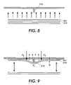
- VCF's use one single straight rib as the corrugator to generate gaps.
- the vacuum required is about 60 mmH 2 O and air flow rate to ensure the generation of the required vacuum (and to produce sufficient fluffer and air knife flow) is about 50 cm.
- the air blower must be large. It requires a high powered motor and it is a major contributor to copier and printer noise. Besides that, a higher vacuum may tend to leave marks on the paper surface, a consequence not welcomed on coated paper.
- the MVCF corrugator consists of a number of variant-height ribs (FIGS. 3, 10 , and 11 ).
- heavyweight paper deflects less than lightweight paper because of the different bending stiffness.
- the second sheet of paper When bent over a rib, the second sheet of paper will follow the first more closely with lightweight paper, i.e., if an identical rib is used, less gap will be generated in the lightweight paper than in the heavyweight paper.
- MVCF can feed both stiff and flexible paper.
- This corrugator was composed of ribs of four different heights. The four side ribs (two on each side) were the tallest, and the two center ribs were the second tallest. If we apply the same amount of load, the heavyweight paper deforms less than the lightweight paper so that if we use the proposed corrugator, the paper will deform into one, two, four, six, and other numbers of spans depending on the paper stiffness.
- FIG. 10 illustrates the paper deformation when the proposed corrugator was used to acquire heavyweight paper.
- FIG. 11 shows the deformed paper curvature when lightweight paper is acquired. The range of paper was from 60 GSM to 300 GSM. Comparing FIGS. 10 and 11 with FIGS. 8 and 9, we found the proposed corrugator generated bending and sliding motions on most parts of the corrugator surface for all grades of paper; while for the heavyweight paper the single corrugator feeder generated the sliding motion only in the center part of the corrugator. Since both the sliding and bending motions are essential in the sheet separation, we believe the proposed corrugator should perform better.
Abstract
Description
Claims (7)
Priority Applications (1)
| Application Number | Priority Date | Filing Date | Title |
|---|---|---|---|
| US09/591,820 US6398206B1 (en) | 2000-06-12 | 2000-06-12 | Sheet feeding apparatus having an air plenum with a corrugated surface |
Applications Claiming Priority (1)
| Application Number | Priority Date | Filing Date | Title |
|---|---|---|---|
| US09/591,820 US6398206B1 (en) | 2000-06-12 | 2000-06-12 | Sheet feeding apparatus having an air plenum with a corrugated surface |
Publications (1)
| Publication Number | Publication Date |
|---|---|
| US6398206B1 true US6398206B1 (en) | 2002-06-04 |
Family
ID=24368079
Family Applications (1)
| Application Number | Title | Priority Date | Filing Date |
|---|---|---|---|
| US09/591,820 Expired - Lifetime US6398206B1 (en) | 2000-06-12 | 2000-06-12 | Sheet feeding apparatus having an air plenum with a corrugated surface |
Country Status (1)
| Country | Link |
|---|---|
| US (1) | US6398206B1 (en) |
Cited By (22)
| Publication number | Priority date | Publication date | Assignee | Title |
|---|---|---|---|---|
| US6619654B2 (en) * | 2001-02-07 | 2003-09-16 | Silverbrook Research Pty Ltd. | Method of separating a sheet of print media from a stack of sheets |
| US20030172795A1 (en) * | 2002-03-15 | 2003-09-18 | Lotfi Belkhir | Page turning apparatus with a vacuum plenum and an adaptive air fluffer |
| US20030200815A1 (en) * | 2002-01-07 | 2003-10-30 | Xerox Corporation | Substrate bending stiffness measurement method and system |
| US6669187B1 (en) * | 2002-06-13 | 2003-12-30 | Xerox Corporation | Rear jet air knife |
| US20040047009A1 (en) * | 2002-09-10 | 2004-03-11 | Taylor Thomas N. | Automated page turning apparatus to assist in viewing pages of a document |
| US20040084833A1 (en) * | 2001-02-19 | 2004-05-06 | Jensen David William | Sheet feeding apparatus for feeding porous sheets of media from a stack of such sheets |
| US20040163028A1 (en) * | 2003-02-18 | 2004-08-19 | Olarig Sompong P. | Technique for implementing chipkill in a memory system |
| US6863272B2 (en) | 2002-08-29 | 2005-03-08 | Xerox Corporation | Sheet feeding apparatus having an adaptive air fluffer |
| US20050156370A1 (en) * | 2004-01-15 | 2005-07-21 | Xerox Corporation | Feeder control system and method |
| US20050211931A1 (en) * | 2004-03-29 | 2005-09-29 | Mahesan Chelvayohan | Media sensor apparatus using a two component media sensor for media absence detection |
| US6994340B2 (en) | 2002-09-12 | 2006-02-07 | Xerox Corporation | Sheet feeding apparatus having an air fluffer |
| US20060170145A1 (en) * | 2005-02-03 | 2006-08-03 | Canon Kabushiki Kaisha | Sheet feeding apparatus and image forming apparatus |
| US20060255525A1 (en) * | 2005-05-13 | 2006-11-16 | Xerox Corporation | Sheet feeder vacuum feed head with variable corrugation |
| US20080134851A1 (en) * | 2006-12-08 | 2008-06-12 | Roach William A | Cutting apparatus with a cutting tip sensor |
| US20080134857A1 (en) * | 2006-12-08 | 2008-06-12 | Roach William A | Cutting head |
| US20080316551A1 (en) * | 2002-09-10 | 2008-12-25 | Kirtas Technologies, Inc. | Automated page turning apparatus to assist in viewing pages of a document |
| US20090180085A1 (en) * | 2008-01-15 | 2009-07-16 | Kirtas Technologies, Inc. | System and method for large format imaging |
| US20090197751A1 (en) * | 2007-12-05 | 2009-08-06 | Greg Gale | Continuous feeder for paper folding machine and paper folding machine incorporating same |
| US20130020755A1 (en) * | 2011-07-22 | 2013-01-24 | Fuji Xerox Co., Ltd. | Medium feeding device and image forming apparatus |
| CN103543624A (en) * | 2012-07-10 | 2014-01-29 | 富士施乐株式会社 | Image forming apparatus, and sheet feeding device |
| US20200218180A1 (en) * | 2017-09-29 | 2020-07-09 | Canon Kabushiki Kaisha | Image forming apparatus |
| US20210171300A1 (en) * | 2019-12-05 | 2021-06-10 | Fuji Xerox Co., Ltd. | Recording-material-transporting device and image forming apparatus |
Citations (12)
| Publication number | Priority date | Publication date | Assignee | Title |
|---|---|---|---|---|
| US2060616A (en) * | 1935-09-05 | 1936-11-10 | New Jersey Machine Corp | Machine for applying adhesive |
| US3154306A (en) * | 1962-10-29 | 1964-10-27 | Harris Intertype Corp | Sheet-gripping sucker |
| US3272549A (en) * | 1965-01-13 | 1966-09-13 | Gen Electric | Materials handling device |
| US4451028A (en) * | 1981-11-27 | 1984-05-29 | Xerox Corporation | Sheet feeding apparatus |
| US5052675A (en) * | 1990-06-21 | 1991-10-01 | Xerox Corporation | Top vacuum corrugation feeder with aerodynamic drag separation |
| US5150892A (en) * | 1990-03-30 | 1992-09-29 | Minolta Camera Kabushiki Kaisha | Sheet feeding apparatus |
| US5156387A (en) * | 1989-10-16 | 1992-10-20 | Fuji Photo Film Co., Ltd. | Suction cup for sheet feed mechanism |
| US5181710A (en) * | 1990-03-20 | 1993-01-26 | Sharp Kabushiki Kaisha | Top sheet feeding apparatus |
| US5190332A (en) * | 1990-09-06 | 1993-03-02 | Smc Kabushiki Kaisha | Suction pad for attracting and holding a workpiece |
| US5257776A (en) * | 1990-01-12 | 1993-11-02 | Fuji Photo Film Co., Ltd. | Device for feeding sheets having a detecting means for detecting misfeeds |
| US6149045A (en) * | 1995-04-26 | 2000-11-21 | Toshiba Tec Kabushiki Kaisha | Paper sheet supplying apparatus having a raised central region for preventing a paper sheet from skewing as the sheet is fed |
| US6264188B1 (en) * | 2000-06-12 | 2001-07-24 | Xerox Corporation | Sheet feeding apparatus having an adaptive air fluffer |
-
2000
- 2000-06-12 US US09/591,820 patent/US6398206B1/en not_active Expired - Lifetime
Patent Citations (12)
| Publication number | Priority date | Publication date | Assignee | Title |
|---|---|---|---|---|
| US2060616A (en) * | 1935-09-05 | 1936-11-10 | New Jersey Machine Corp | Machine for applying adhesive |
| US3154306A (en) * | 1962-10-29 | 1964-10-27 | Harris Intertype Corp | Sheet-gripping sucker |
| US3272549A (en) * | 1965-01-13 | 1966-09-13 | Gen Electric | Materials handling device |
| US4451028A (en) * | 1981-11-27 | 1984-05-29 | Xerox Corporation | Sheet feeding apparatus |
| US5156387A (en) * | 1989-10-16 | 1992-10-20 | Fuji Photo Film Co., Ltd. | Suction cup for sheet feed mechanism |
| US5257776A (en) * | 1990-01-12 | 1993-11-02 | Fuji Photo Film Co., Ltd. | Device for feeding sheets having a detecting means for detecting misfeeds |
| US5181710A (en) * | 1990-03-20 | 1993-01-26 | Sharp Kabushiki Kaisha | Top sheet feeding apparatus |
| US5150892A (en) * | 1990-03-30 | 1992-09-29 | Minolta Camera Kabushiki Kaisha | Sheet feeding apparatus |
| US5052675A (en) * | 1990-06-21 | 1991-10-01 | Xerox Corporation | Top vacuum corrugation feeder with aerodynamic drag separation |
| US5190332A (en) * | 1990-09-06 | 1993-03-02 | Smc Kabushiki Kaisha | Suction pad for attracting and holding a workpiece |
| US6149045A (en) * | 1995-04-26 | 2000-11-21 | Toshiba Tec Kabushiki Kaisha | Paper sheet supplying apparatus having a raised central region for preventing a paper sheet from skewing as the sheet is fed |
| US6264188B1 (en) * | 2000-06-12 | 2001-07-24 | Xerox Corporation | Sheet feeding apparatus having an adaptive air fluffer |
Cited By (67)
| Publication number | Priority date | Publication date | Assignee | Title |
|---|---|---|---|---|
| US20080303203A1 (en) * | 2001-02-06 | 2008-12-11 | Silverbrook Research Pty Ltd | Paper feed mechanism for a printing station |
| US7874556B2 (en) | 2001-02-06 | 2011-01-25 | Silverbrook Research Pty Ltd | Printer with reversible air flow sheet picker |
| US20090194933A1 (en) * | 2001-02-06 | 2009-08-06 | Silverbrook Research Pty Ltd | Printer With Reversible Air Flow Sheet Picker |
| US20040130090A1 (en) * | 2001-02-07 | 2004-07-08 | Silverbrook Research Pty Ltd | Method of feeding sheets of media from a stack |
| US20040100011A1 (en) * | 2001-02-07 | 2004-05-27 | Jensen David William | Printing assembly for printing on sheets of media from a stack |
| US20040032078A1 (en) * | 2001-02-07 | 2004-02-19 | Silverbrook Research Pty Ltd | Print media feed alignment mechanism |
| US7431281B2 (en) * | 2001-02-07 | 2008-10-07 | Silverbrook Research Pty Ltd | Method of separating a sheet of print media from a stack of sheets |
| US20040070135A1 (en) * | 2001-02-07 | 2004-04-15 | Jensen David William | Method of separating a sheet of print media from a stack of sheets |
| US20050082741A1 (en) * | 2001-02-07 | 2005-04-21 | Jensen David W. | Media feed mechanism for feeding sheets of porous media from a stack |
| US20050062824A1 (en) * | 2001-02-07 | 2005-03-24 | David William Jensen | Printer incorporating a sheet pick-up device |
| US7533877B2 (en) | 2001-02-07 | 2009-05-19 | Silverbrook Research Pty Ltd | High speed printer with gas-operated sheet feeding |
| US20040094888A1 (en) * | 2001-02-07 | 2004-05-20 | Silverbrook Research Pty Ltd | Apparatus for feeding sheets of media from a stack |
| US6848686B2 (en) | 2001-02-07 | 2005-02-01 | Silverbrook Research Pty Ltd | Printing assembly for printing on sheets of media from a stack |
| US20070284806A1 (en) * | 2001-02-07 | 2007-12-13 | Silverbrook Research Pty Ltd | Media Feed Assembly For A Printing Device |
| US7032899B2 (en) | 2001-02-07 | 2006-04-25 | Silverbrook Research Pty Ltd | Print media feed alignment mechanism |
| US7243916B2 (en) | 2001-02-07 | 2007-07-17 | Silverbrook Research Pty Ltd | Apparatus for feeding sheets of media from a stack |
| US20070108695A9 (en) * | 2001-02-07 | 2007-05-17 | Jensen David W | Media feed mechanism for feeding sheets of porous media from a stack |
| US6619654B2 (en) * | 2001-02-07 | 2003-09-16 | Silverbrook Research Pty Ltd. | Method of separating a sheet of print media from a stack of sheets |
| US6854724B2 (en) | 2001-02-07 | 2005-02-15 | Silverbrook Research Pty Ltd | Pneumatic sheet transportation |
| US6830246B2 (en) | 2001-02-07 | 2004-12-14 | Silverbrook Research Pty Ltd | Apparatus for feeding sheets of media from a stack |
| US6851671B2 (en) | 2001-02-07 | 2005-02-08 | Silverbrook Research Pty Ltd | Method of feeding sheets of media from a stack |
| US20040089995A1 (en) * | 2001-02-19 | 2004-05-13 | Jensen David William | Device for lifting a porous sheet from a stack of such sheets |
| US6834851B2 (en) * | 2001-02-19 | 2004-12-28 | Silverbrook Research Pty Ltd | Sheet feeding apparatus for feeding porous sheets of media from a stack of such sheets |
| US6820871B2 (en) * | 2001-02-19 | 2004-11-23 | Silverbrook Research Pty Ltd | Printer for printing on porous sheets of media fed from a stack of such sheets |
| US20070145669A9 (en) * | 2001-02-19 | 2007-06-28 | David William Jensen | Feed mechanism for feeding sheets from a stack to a printer |
| US20050056987A1 (en) * | 2001-02-19 | 2005-03-17 | Jensen David William | Method of feeding porous sheets of media from media stack |
| US20050062212A1 (en) * | 2001-02-19 | 2005-03-24 | David William Jensen | Feed mechanism for feeding sheets from a stack to a printer |
| US20040084832A1 (en) * | 2001-02-19 | 2004-05-06 | Jensen David William | Printer for printing on porous sheets of media fed from a stack of such sheets |
| US20040084833A1 (en) * | 2001-02-19 | 2004-05-06 | Jensen David William | Sheet feeding apparatus for feeding porous sheets of media from a stack of such sheets |
| US6896252B2 (en) * | 2001-02-19 | 2005-05-24 | Silverbrook Research Pty Ltd | Device for lifting a porous sheet from a stack of such sheets |
| US7172191B2 (en) | 2001-02-19 | 2007-02-06 | Silverbrook Research Pty Ltd | Method of feeding porous sheets of media from media stack |
| US20040217539A1 (en) * | 2002-01-07 | 2004-11-04 | Xerox Corporation | Substrate bending stiffness measurement method and system |
| US6772628B2 (en) | 2002-01-07 | 2004-08-10 | Xerox Corporation | Substrate bending stiffness measurement method and system |
| US20030200815A1 (en) * | 2002-01-07 | 2003-10-30 | Xerox Corporation | Substrate bending stiffness measurement method and system |
| US20030205093A1 (en) * | 2002-01-07 | 2003-11-06 | Xerox Corporation | Substrate bending stiffness measurement method and system |
| US7374161B2 (en) | 2002-01-07 | 2008-05-20 | Xerox Corporation | Substrate bending stiffness measurement method and system |
| US6748801B2 (en) | 2002-01-07 | 2004-06-15 | Xerox Corporation | Substrate bending stiffness measurement method and system |
| US20030172795A1 (en) * | 2002-03-15 | 2003-09-18 | Lotfi Belkhir | Page turning apparatus with a vacuum plenum and an adaptive air fluffer |
| US7595915B2 (en) | 2002-03-15 | 2009-09-29 | Kirtas Technologies, Inc. | Page turning apparatus with a vacuum plenum and an adaptive air fluffer |
| US6669187B1 (en) * | 2002-06-13 | 2003-12-30 | Xerox Corporation | Rear jet air knife |
| US6863272B2 (en) | 2002-08-29 | 2005-03-08 | Xerox Corporation | Sheet feeding apparatus having an adaptive air fluffer |
| US20040047009A1 (en) * | 2002-09-10 | 2004-03-11 | Taylor Thomas N. | Automated page turning apparatus to assist in viewing pages of a document |
| US7557965B2 (en) | 2002-09-10 | 2009-07-07 | Kirtas Technologies, Inc. | Automated page turning apparatus to assist in viewing pages of a document |
| US20080316551A1 (en) * | 2002-09-10 | 2008-12-25 | Kirtas Technologies, Inc. | Automated page turning apparatus to assist in viewing pages of a document |
| US6994340B2 (en) | 2002-09-12 | 2006-02-07 | Xerox Corporation | Sheet feeding apparatus having an air fluffer |
| US20040163028A1 (en) * | 2003-02-18 | 2004-08-19 | Olarig Sompong P. | Technique for implementing chipkill in a memory system |
| US7237771B2 (en) | 2004-01-15 | 2007-07-03 | Xerox Corporation | Feeder control system and method |
| US20050156370A1 (en) * | 2004-01-15 | 2005-07-21 | Xerox Corporation | Feeder control system and method |
| US20050211931A1 (en) * | 2004-03-29 | 2005-09-29 | Mahesan Chelvayohan | Media sensor apparatus using a two component media sensor for media absence detection |
| US7205561B2 (en) | 2004-03-29 | 2007-04-17 | Lexmark International, Inc. | Media sensor apparatus using a two component media sensor for media absence detection |
| US7364150B2 (en) * | 2005-02-03 | 2008-04-29 | Canon Kabushiki Kaisha | Sheet feeding apparatus and image forming apparatus using heating member on sheet tray |
| US20060170145A1 (en) * | 2005-02-03 | 2006-08-03 | Canon Kabushiki Kaisha | Sheet feeding apparatus and image forming apparatus |
| US20060255525A1 (en) * | 2005-05-13 | 2006-11-16 | Xerox Corporation | Sheet feeder vacuum feed head with variable corrugation |
| US7328895B2 (en) | 2005-05-13 | 2008-02-12 | Xerox Corporation | Sheet feeder vacuum feed head with variable corrugation |
| US20080134857A1 (en) * | 2006-12-08 | 2008-06-12 | Roach William A | Cutting head |
| US20080134851A1 (en) * | 2006-12-08 | 2008-06-12 | Roach William A | Cutting apparatus with a cutting tip sensor |
| US20090197751A1 (en) * | 2007-12-05 | 2009-08-06 | Greg Gale | Continuous feeder for paper folding machine and paper folding machine incorporating same |
| US7938764B2 (en) * | 2007-12-05 | 2011-05-10 | Greg Gale | Continuous feeder for paper folding machine and paper folding machine incorporating the same |
| US20090180085A1 (en) * | 2008-01-15 | 2009-07-16 | Kirtas Technologies, Inc. | System and method for large format imaging |
| US20130020755A1 (en) * | 2011-07-22 | 2013-01-24 | Fuji Xerox Co., Ltd. | Medium feeding device and image forming apparatus |
| US8662495B2 (en) * | 2011-07-22 | 2014-03-04 | Fuji Xerox Co., Ltd. | Medium feeding device and image forming apparatus |
| CN103543624A (en) * | 2012-07-10 | 2014-01-29 | 富士施乐株式会社 | Image forming apparatus, and sheet feeding device |
| CN103543624B (en) * | 2012-07-10 | 2017-08-01 | 富士施乐株式会社 | Image forming apparatus and sheet feeding apparatus |
| US20200218180A1 (en) * | 2017-09-29 | 2020-07-09 | Canon Kabushiki Kaisha | Image forming apparatus |
| US10935910B2 (en) * | 2017-09-29 | 2021-03-02 | Canon Kabushiki Kaisha | Image forming apparatus in which corrugated shape is formed in width direction on sheet to which air is blown |
| US20210171300A1 (en) * | 2019-12-05 | 2021-06-10 | Fuji Xerox Co., Ltd. | Recording-material-transporting device and image forming apparatus |
| US11565899B2 (en) * | 2019-12-05 | 2023-01-31 | Fujifilm Business Innovation Corp. | Recording-material-transporting device and image forming apparatus |
Similar Documents
| Publication | Publication Date | Title |
|---|---|---|
| US6264188B1 (en) | Sheet feeding apparatus having an adaptive air fluffer | |
| US6398208B1 (en) | Sheet feeding apparatus having an air plenum with a leaky seal | |
| US6398206B1 (en) | Sheet feeding apparatus having an air plenum with a corrugated surface | |
| US6398207B1 (en) | Sheet feeding apparatus having an air plenum with a seal | |
| US6352255B1 (en) | Reversing shuttle feeder | |
| US5539511A (en) | Multilevel/duplex image sheet decurling apparatus | |
| US7290764B2 (en) | Modular guide apparatus for tab stock received in a feeder tray | |
| US6669187B1 (en) | Rear jet air knife | |
| US5518231A (en) | Self adjusting sheet gripping apparatus | |
| US6863272B2 (en) | Sheet feeding apparatus having an adaptive air fluffer | |
| US6945525B2 (en) | Sheet feeding apparatus having an adaptive air fluffer | |
| US6994340B2 (en) | Sheet feeding apparatus having an air fluffer | |
| EP0493022B1 (en) | Sheet transport apparatus | |
| US5245393A (en) | Fuser method and apparatus for reducing media curl in electrophotographic printers | |
| US5580044A (en) | Low aspect ratio, wide belt/long roller tracking system | |
| JPH04234064A (en) | Encoder roll | |
| US6505030B1 (en) | Pre-fuser transport assembly for handling a variety of sheets, and a reproduction machine having same | |
| US5967511A (en) | Sheet registration assembly including a force reducing deskew roll | |
| US7310491B2 (en) | Non-gouging sheet stripper assembly | |
| US5533720A (en) | Sheet control baffle for use in an electrophotographic printing machine | |
| US5227854A (en) | Sheet transport system with sheet velocity manipulation | |
| EP0493021B1 (en) | Sheet transport apparatus | |
| JPH09319168A (en) | Copying machine/printer | |
| US6212345B1 (en) | Image forming apparatus with different inertial conditions among image supports | |
| US5153652A (en) | Developed image transfer apparatus and method with gas directing means |
Legal Events
| Date | Code | Title | Description |
|---|---|---|---|
| AS | Assignment |
Owner name: XEROX CORPORATION, CONNECTICUT Free format text: ASSIGNMENT OF ASSIGNORS INTEREST;ASSIGNORS:YANG, MING;TAYLOR, THOMAS N.;REEL/FRAME:010905/0463 Effective date: 20000609 |
|
| STCF | Information on status: patent grant |
Free format text: PATENTED CASE |
|
| AS | Assignment |
Owner name: BANK ONE, NA, AS ADMINISTRATIVE AGENT, ILLINOIS Free format text: SECURITY AGREEMENT;ASSIGNOR:XEROX CORPORATION;REEL/FRAME:013111/0001 Effective date: 20020621 Owner name: BANK ONE, NA, AS ADMINISTRATIVE AGENT,ILLINOIS Free format text: SECURITY AGREEMENT;ASSIGNOR:XEROX CORPORATION;REEL/FRAME:013111/0001 Effective date: 20020621 |
|
| AS | Assignment |
Owner name: JPMORGAN CHASE BANK, AS COLLATERAL AGENT, TEXAS Free format text: SECURITY AGREEMENT;ASSIGNOR:XEROX CORPORATION;REEL/FRAME:015134/0476 Effective date: 20030625 Owner name: JPMORGAN CHASE BANK, AS COLLATERAL AGENT,TEXAS Free format text: SECURITY AGREEMENT;ASSIGNOR:XEROX CORPORATION;REEL/FRAME:015134/0476 Effective date: 20030625 |
|
| FPAY | Fee payment |
Year of fee payment: 4 |
|
| FPAY | Fee payment |
Year of fee payment: 8 |
|
| FPAY | Fee payment |
Year of fee payment: 12 |
|
| AS | Assignment |
Owner name: XEROX CORPORATION, CONNECTICUT Free format text: RELEASE BY SECURED PARTY;ASSIGNOR:JPMORGAN CHASE BANK, N.A. AS SUCCESSOR-IN-INTEREST ADMINISTRATIVE AGENT AND COLLATERAL AGENT TO BANK ONE, N.A.;REEL/FRAME:061388/0388 Effective date: 20220822 Owner name: XEROX CORPORATION, CONNECTICUT Free format text: RELEASE BY SECURED PARTY;ASSIGNOR:JPMORGAN CHASE BANK, N.A. AS SUCCESSOR-IN-INTEREST ADMINISTRATIVE AGENT AND COLLATERAL AGENT TO JPMORGAN CHASE BANK;REEL/FRAME:066728/0193 Effective date: 20220822 |