US6398446B1 - Ball joint components and methods for making same - Google Patents
Ball joint components and methods for making same Download PDFInfo
- Publication number
- US6398446B1 US6398446B1 US09/255,979 US25597999A US6398446B1 US 6398446 B1 US6398446 B1 US 6398446B1 US 25597999 A US25597999 A US 25597999A US 6398446 B1 US6398446 B1 US 6398446B1
- Authority
- US
- United States
- Prior art keywords
- ball
- housing
- socket
- stud
- seal
- Prior art date
- Legal status (The legal status is an assumption and is not a legal conclusion. Google has not performed a legal analysis and makes no representation as to the accuracy of the status listed.)
- Expired - Fee Related
Links
Images


Classifications
-
- F—MECHANICAL ENGINEERING; LIGHTING; HEATING; WEAPONS; BLASTING
- F16—ENGINEERING ELEMENTS AND UNITS; GENERAL MEASURES FOR PRODUCING AND MAINTAINING EFFECTIVE FUNCTIONING OF MACHINES OR INSTALLATIONS; THERMAL INSULATION IN GENERAL
- F16C—SHAFTS; FLEXIBLE SHAFTS; ELEMENTS OR CRANKSHAFT MECHANISMS; ROTARY BODIES OTHER THAN GEARING ELEMENTS; BEARINGS
- F16C7/00—Connecting-rods or like links pivoted at both ends; Construction of connecting-rod heads
- F16C7/02—Constructions of connecting-rods with constant length
-
- B—PERFORMING OPERATIONS; TRANSPORTING
- B60—VEHICLES IN GENERAL
- B60G—VEHICLE SUSPENSION ARRANGEMENTS
- B60G7/00—Pivoted suspension arms; Accessories thereof
- B60G7/001—Suspension arms, e.g. constructional features
-
- B—PERFORMING OPERATIONS; TRANSPORTING
- B60—VEHICLES IN GENERAL
- B60G—VEHICLE SUSPENSION ARRANGEMENTS
- B60G7/00—Pivoted suspension arms; Accessories thereof
- B60G7/005—Ball joints
-
- F—MECHANICAL ENGINEERING; LIGHTING; HEATING; WEAPONS; BLASTING
- F16—ENGINEERING ELEMENTS AND UNITS; GENERAL MEASURES FOR PRODUCING AND MAINTAINING EFFECTIVE FUNCTIONING OF MACHINES OR INSTALLATIONS; THERMAL INSULATION IN GENERAL
- F16C—SHAFTS; FLEXIBLE SHAFTS; ELEMENTS OR CRANKSHAFT MECHANISMS; ROTARY BODIES OTHER THAN GEARING ELEMENTS; BEARINGS
- F16C11/00—Pivots; Pivotal connections
- F16C11/04—Pivotal connections
- F16C11/06—Ball-joints; Other joints having more than one degree of angular freedom, i.e. universal joints
- F16C11/0604—Construction of the male part
-
- F—MECHANICAL ENGINEERING; LIGHTING; HEATING; WEAPONS; BLASTING
- F16—ENGINEERING ELEMENTS AND UNITS; GENERAL MEASURES FOR PRODUCING AND MAINTAINING EFFECTIVE FUNCTIONING OF MACHINES OR INSTALLATIONS; THERMAL INSULATION IN GENERAL
- F16C—SHAFTS; FLEXIBLE SHAFTS; ELEMENTS OR CRANKSHAFT MECHANISMS; ROTARY BODIES OTHER THAN GEARING ELEMENTS; BEARINGS
- F16C11/00—Pivots; Pivotal connections
- F16C11/04—Pivotal connections
- F16C11/06—Ball-joints; Other joints having more than one degree of angular freedom, i.e. universal joints
- F16C11/0619—Ball-joints; Other joints having more than one degree of angular freedom, i.e. universal joints the female part comprising a blind socket receiving the male part
- F16C11/0623—Construction or details of the socket member
- F16C11/0628—Construction or details of the socket member with linings
- F16C11/0633—Construction or details of the socket member with linings the linings being made of plastics
-
- F—MECHANICAL ENGINEERING; LIGHTING; HEATING; WEAPONS; BLASTING
- F16—ENGINEERING ELEMENTS AND UNITS; GENERAL MEASURES FOR PRODUCING AND MAINTAINING EFFECTIVE FUNCTIONING OF MACHINES OR INSTALLATIONS; THERMAL INSULATION IN GENERAL
- F16C—SHAFTS; FLEXIBLE SHAFTS; ELEMENTS OR CRANKSHAFT MECHANISMS; ROTARY BODIES OTHER THAN GEARING ELEMENTS; BEARINGS
- F16C11/00—Pivots; Pivotal connections
- F16C11/04—Pivotal connections
- F16C11/06—Ball-joints; Other joints having more than one degree of angular freedom, i.e. universal joints
- F16C11/0619—Ball-joints; Other joints having more than one degree of angular freedom, i.e. universal joints the female part comprising a blind socket receiving the male part
- F16C11/0623—Construction or details of the socket member
- F16C11/0657—Construction or details of the socket member the socket member being mainly made of plastics
-
- F—MECHANICAL ENGINEERING; LIGHTING; HEATING; WEAPONS; BLASTING
- F16—ENGINEERING ELEMENTS AND UNITS; GENERAL MEASURES FOR PRODUCING AND MAINTAINING EFFECTIVE FUNCTIONING OF MACHINES OR INSTALLATIONS; THERMAL INSULATION IN GENERAL
- F16C—SHAFTS; FLEXIBLE SHAFTS; ELEMENTS OR CRANKSHAFT MECHANISMS; ROTARY BODIES OTHER THAN GEARING ELEMENTS; BEARINGS
- F16C11/00—Pivots; Pivotal connections
- F16C11/04—Pivotal connections
- F16C11/06—Ball-joints; Other joints having more than one degree of angular freedom, i.e. universal joints
- F16C11/0666—Sealing means between the socket and the inner member shaft
- F16C11/0671—Sealing means between the socket and the inner member shaft allowing operative relative movement of joint parts due to flexing of the sealing means
-
- F—MECHANICAL ENGINEERING; LIGHTING; HEATING; WEAPONS; BLASTING
- F16—ENGINEERING ELEMENTS AND UNITS; GENERAL MEASURES FOR PRODUCING AND MAINTAINING EFFECTIVE FUNCTIONING OF MACHINES OR INSTALLATIONS; THERMAL INSULATION IN GENERAL
- F16C—SHAFTS; FLEXIBLE SHAFTS; ELEMENTS OR CRANKSHAFT MECHANISMS; ROTARY BODIES OTHER THAN GEARING ELEMENTS; BEARINGS
- F16C11/00—Pivots; Pivotal connections
- F16C11/04—Pivotal connections
- F16C11/06—Ball-joints; Other joints having more than one degree of angular freedom, i.e. universal joints
- F16C11/0685—Manufacture of ball-joints and parts thereof, e.g. assembly of ball-joints
- F16C11/069—Manufacture of ball-joints and parts thereof, e.g. assembly of ball-joints with at least one separate part to retain the ball member in the socket; Quick-release systems
-
- B—PERFORMING OPERATIONS; TRANSPORTING
- B60—VEHICLES IN GENERAL
- B60G—VEHICLE SUSPENSION ARRANGEMENTS
- B60G2204/00—Indexing codes related to suspensions per se or to auxiliary parts
- B60G2204/40—Auxiliary suspension parts; Adjustment of suspensions
- B60G2204/416—Ball or spherical joints
-
- B—PERFORMING OPERATIONS; TRANSPORTING
- B60—VEHICLES IN GENERAL
- B60G—VEHICLE SUSPENSION ARRANGEMENTS
- B60G2206/00—Indexing codes related to the manufacturing of suspensions: constructional features, the materials used, procedures or tools
- B60G2206/01—Constructional features of suspension elements, e.g. arms, dampers, springs
- B60G2206/10—Constructional features of arms
- B60G2206/11—Constructional features of arms the arm being a radius or track or torque or steering rod or stabiliser end link
-
- F—MECHANICAL ENGINEERING; LIGHTING; HEATING; WEAPONS; BLASTING
- F16—ENGINEERING ELEMENTS AND UNITS; GENERAL MEASURES FOR PRODUCING AND MAINTAINING EFFECTIVE FUNCTIONING OF MACHINES OR INSTALLATIONS; THERMAL INSULATION IN GENERAL
- F16C—SHAFTS; FLEXIBLE SHAFTS; ELEMENTS OR CRANKSHAFT MECHANISMS; ROTARY BODIES OTHER THAN GEARING ELEMENTS; BEARINGS
- F16C2326/00—Articles relating to transporting
- F16C2326/01—Parts of vehicles in general
- F16C2326/05—Vehicle suspensions, e.g. bearings, pivots or connecting rods used therein
-
- Y—GENERAL TAGGING OF NEW TECHNOLOGICAL DEVELOPMENTS; GENERAL TAGGING OF CROSS-SECTIONAL TECHNOLOGIES SPANNING OVER SEVERAL SECTIONS OF THE IPC; TECHNICAL SUBJECTS COVERED BY FORMER USPC CROSS-REFERENCE ART COLLECTIONS [XRACs] AND DIGESTS
- Y10—TECHNICAL SUBJECTS COVERED BY FORMER USPC
- Y10T—TECHNICAL SUBJECTS COVERED BY FORMER US CLASSIFICATION
- Y10T403/00—Joints and connections
- Y10T403/32—Articulated members
- Y10T403/32606—Pivoted
- Y10T403/32631—Universal ball and socket
- Y10T403/32681—Composite ball
- Y10T403/32704—Stud extends into ball
-
- Y—GENERAL TAGGING OF NEW TECHNOLOGICAL DEVELOPMENTS; GENERAL TAGGING OF CROSS-SECTIONAL TECHNOLOGIES SPANNING OVER SEVERAL SECTIONS OF THE IPC; TECHNICAL SUBJECTS COVERED BY FORMER USPC CROSS-REFERENCE ART COLLECTIONS [XRACs] AND DIGESTS
- Y10—TECHNICAL SUBJECTS COVERED BY FORMER USPC
- Y10T—TECHNICAL SUBJECTS COVERED BY FORMER US CLASSIFICATION
- Y10T403/00—Joints and connections
- Y10T403/32—Articulated members
- Y10T403/32606—Pivoted
- Y10T403/32631—Universal ball and socket
- Y10T403/32729—Externally packed
-
- Y—GENERAL TAGGING OF NEW TECHNOLOGICAL DEVELOPMENTS; GENERAL TAGGING OF CROSS-SECTIONAL TECHNOLOGIES SPANNING OVER SEVERAL SECTIONS OF THE IPC; TECHNICAL SUBJECTS COVERED BY FORMER USPC CROSS-REFERENCE ART COLLECTIONS [XRACs] AND DIGESTS
- Y10—TECHNICAL SUBJECTS COVERED BY FORMER USPC
- Y10T—TECHNICAL SUBJECTS COVERED BY FORMER US CLASSIFICATION
- Y10T403/00—Joints and connections
- Y10T403/32—Articulated members
- Y10T403/32606—Pivoted
- Y10T403/32631—Universal ball and socket
- Y10T403/32737—Universal ball and socket including liner, shim, or discrete seat
Definitions
- the present invention relates to ball joints, such as ball joints used in automotive suspension systems.
- White U.S. Pat. No. 3,023,038 discloses a ball stud that employs a ball that is separately formed from and then assembled on the stud.
- the preferred embodiments described below include a number of improvements over the prior art of the previous section. These improvements will be described in detail below.
- the improvements relate to a new sealing approach that differs from the conventional boot, to a new housing/ball socket assembly that is secured together in a way that provides strength advantages, to a new ball stud/ball assembly that provides high strength and cost advantages, to a new ball joint housing/link assembly that provides cost and strength advantages, and to a new approach for retaining a boot on a ball stud that again provides cost advantages.
- FIG. 1 is a side view of a ball joint link that incorporates a preferred embodiment of the present invention.
- FIG. 2 is a top view taken along line 2 — 2 of FIG. 1 .
- FIG. 3 is a perspective view of one of the ball joint housings included in the embodiment of FIG. 1 .
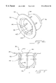
- FIG. 4 is a perspective view of one of the ball sockets included in the embodiment of FIG. 1 .
- FIG. 5 is a cross-sectional view of the ball socket of FIG. 4 .
- FIG. 6 is a cross-sectional view of one of the ball stud stems included in the embodiment of FIG. 1 .
- FIG. 7 is a cross-sectional view of one of the ball stud ball portions included in the embodiment of FIG. 1 .
- FIG. 8 is a side view of a portion of the link included in the embodiment of FIG. 1 .
- FIG. 9 is a cross-sectional view of one end of the ball joint link of FIG. 1 .
- FIG. 10 is a cross-sectional view of a portion of an alternative embodiment of the ball stud stem and boot of FIG. 1 .
- FIGS. 1 and 2 show two views of a ball joint assembly 10 that incorporates a preferred embodiment of this invention.
- the assembly 10 includes a ball joint 12 mounted at each end of a link 22 .
- Each ball joint 12 comprises a respective housing 14 and ball stud 16 .
- the ball stud 16 is described in greater detail below, but in FIGS. 1 and 2 it can be seen that each ball stud 16 includes a stem 18 that includes a threaded portion extending outwardly from the respective housing 14 .
- Each ball stud 16 is mounted to articulate over a prescribed range with respect to the housing 14 , and a boot 20 is secured between the ball stud 16 and the housing 14 to protect the ball joint 12 from grit and other contamination.
- the following paragraphs will describe major component parts of the assembly 10 , before turning to a discussion of the manner in which these parts cooperate and are assembled.
- FIG. 3 shows a perspective view of the housing 14 , which defines a first cavity 24 and a second cavity 26 .
- the housing 14 is injection molded from a high strength thermoplastic material.
- the housing 14 includes ribs 28 that provide structural strength.
- the first cavity 24 receives a ball socket 30 as shown in FIGS. 4 and 5.
- the ball socket 30 includes a top portion 32 , a sidewall portion 34 and a bottom portion 36 .
- the top portion 32 defines an outwardly extending annular flange 38 and an array of slots 40 that extend partially into the sidewall portion 34 .
- the sidewall portion 34 and the bottom portion 36 cooperate to form a spherical recess 42 , and the bottom portion 36 seals and strengthens the lower portion of the ball socket 30 .
- the top portion 32 of the ball socket 30 defines a first annular surface 44 that faces the ball stud in the assembled arrangement.
- FIG. 6 shows a cross-sectional view of the stem 18 of the ball stud.
- the stem 18 defines a longitudinal axis 46 , a threaded portion 48 , and an end portion 50 . Intermediate the threaded portion 48 and the end portion 50 , the stem 18 forms an integral raised annular flange 52 that terminates on one side in a shoulder 54 .
- the stem 18 is preferably formed of a high-strength material such as steel.
- the ball stud stem 18 is well suited for fabrication using low cost, high quality, cold-forming processes.
- the ball stud also includes a ball portion 56 that defines a spherical outer surface 58 , a central opening 60 and a recess 62 .
- the recess 62 lightens the ball portion 56 , and both ends of the opening 60 are preferably provided with a respective chamfer or radius.
- the term “spherical surface” is intended broadly to encompass surfaces that extend over only a portion of a sphere, such as the outer surface 58 .
- FIG. 8 shows a portion of the link 22 prior to assembly.
- the link 22 includes an end 64 that includes a knurled surface 66 that provides an irregular shape.
- the end 66 also includes a chamfer 68 .
- the knurled surface 66 can include a 45° male diamond knurl that is raised by 0.36 to 0.48 mm and includes 18-22 grooves per inch.
- the link 22 is preferably tubular, and it can be formed of an aluminum tube,
- FIG. 9 shows a cross-sectional view of one of the ball joints 12 in its assembled condition.
- the ball stud 16 is first assembled by placing a washer 70 on the shoulder 54 and crimping the stem 18 to hold the washer 70 in place. This forms a two-part assembly that defines a groove 72 between the washer 70 and the ridge or flange 52 .
- the next step in assembling the ball stud 16 is to press fit the ball portion 56 on the stem end 50 until the ball portion 56 is firmly seated against the adjacent shoulder of the stem 18 . Then the end portion 50 is upset, as for example with a riveting operation, to secure the ball portion 56 in place.
- the ball stud 16 is then assembled with the ball socket 30 by snapping the ball portion 56 into the ball socket 30 .
- the slots 40 (FIGS. 4-5) allow the top portion 32 to expand radially to facilitate this assembly.
- the ball socket 30 is pressed into the first cavity 24 of the housing 14 and an ultrasonic weld joint 74 is formed between the housing 14 and the bottom portion 36 of the ball socket 30 .
- the weld joint 74 and the threaded portion 48 are on opposite sides of a plane P that passes through the center line of the link 22 and the ball portion 56 . This places the weld joint 74 in a relatively low-stress region of the housing 14 and in this way improves the strength of the assembly.
- the closed bottom portion 36 seals the ball socket 30 and adds to the strength of both the ball socket 30 and the weld joint 74 .
- annular seal 76 can be installed between the ball stud stem 18 and the ball socket 30 .
- the annular seal 76 includes an inner portion 78 that is adhered to the ball stud stem 18 and an outer portion 80 that is adhered to the ball socket 30 .
- the outer portion 80 defines a second surface 82 that is radially outwardly facing and that is directly adhered to the radially inwardly facing first surface 44 . Note that the first surface 44 , the ball portion 56 , and the ball stud stem 18 cooperate to form a trough 84 .
- the annular seal 76 is shaped as an annular disk oriented parallel to a plane transverse to the longitudinal axis 46 .
- the seal 76 can be formed by flowing a liquid polymer gel into the trough 84 and then curing the polymer gel to cause it to adhere to both the first surface 44 of the ball socket 30 (and therefore to the housing 14 ) and to the ball stud stem 18 .
- the annular seal 76 is stretchable, and preferably has an elongation limit of greater than 50%. When properly chemically adhered, the annular seal 76 forms a hermetic seal which is expected to offer improvements over mechanical, surface pressure sealing joints.
- the annular seal 46 elongates and compresses such that it provides a weather-tight seal and remains adhesively secured both to the ball socket 30 and the ball stud stem 18 .
- the boot 20 includes an inner sealing surface 86 and an outer sealing surface 88 .
- the outer sealing surface 88 is sealed against the outer surface of the housing 14 and held in place by a retaining ring 90 which may be of steel or a suitable polymer.
- the inner sealing surface 86 defines an annular ridge 92 shaped to fit within the groove 72 .
- the inner sealing surface 86 is held in place by another retaining ring 94 , which also may be formed of steel or a suitable polymer.
- the housing 14 is preferably assembled to the link 22 by first heating the end 64 to a temperature higher than the softening temperature of the housing 14 .
- the heated end 64 is then pressed into the second cavity 26 .
- the second cavity 26 is tapered to facilitate this insertion, and the chamfer 68 also assists in centering the end 64 in the second cavity 26 .
- the end 64 is held while the softened plastic material of the housing 14 flows into the knurled surface 66 to form a strong mechanical joint.
- FIG. 10 relates to an alternative embodiment, in which the ball stud includes a flange 96 that defines an annular ridge 98 .
- the boot 100 defines a groove 102 shaped to receive the ridge 98 .
- the housing 14 can be injection molded from a thermoplastic resin such as 30% glass filled nylon 6/6.
- the ball socket 30 can be injection molded from a thermoplastic material such as unfilled nylon 6/6.
- the ball stud stem 18 can be formed of a steel alloy such as 4037 steel (IFI Class 10.9 (RC33-39)).
- the ball portion 56 can be formed of a metal such as 1008 or 1010 alloy.
- the ball stud stem 18 is plated with a material such as zinc that provides corrosion resistance and the ball portion 56 is coated with a material such as TeflonTM that acts as a solid lubricant and provides a low friction surface.
- the link 22 can be formed of an aluminum alloy such as 6061-T6 (ASTM B210M-95).
- the preferred knurl for the knurl surface 66 provides a 90° angle between opposite slopes of the knurl to create a sharp diamond knurl.
- a preferred polymer gel for the annular seal 76 is a urethane resin such as type UR-312 resin (Thermoset Plastics Co., Indianapolis, Ind.).
- the end of the link 22 is heated to about 600° F. in order to melt the plastic housing material partially and allow it to flow into the knurled tube surface for a strong mechanical joint after the parts cool.
- the improved annular seal described above can be used with other types of ball studs and other types of housings.
- the annular seal can be adhered directly to the housing in ball joints that do not include a separate ball socket.
- the term “housing” is intended to include a ball socket when a ball socket is used.
- the improved annular seal can be used with or without a boot.
- the improved boot retention system of FIG. 10 can be used in any suitable ball joint, including ball joints having other types of ball studs and housings, whether or not the annular seal 76 is used.
- the link 22 can have other cross sectional shapes, and can be formed of other metals or of solid construction.
- Another alternative is to use a composite rod for the link 22 which is adhesively secured to the housing. Also, adhesive bonding techniques can be used to form the joint 74 .
- the link can be assembled with the housing before or after the ball socket is assembled with the housing.
- chamfer is intended broadly to encompass a radius.
Abstract
Description
Claims (28)
Priority Applications (6)
| Application Number | Priority Date | Filing Date | Title |
|---|---|---|---|
| US09/255,979 US6398446B1 (en) | 1997-11-24 | 1999-02-23 | Ball joint components and methods for making same |
| CA002269435A CA2269435C (en) | 1999-02-23 | 1999-04-20 | Ball joint components and methods for making same |
| DE69922920T DE69922920T2 (en) | 1999-02-23 | 1999-04-26 | Ball joint components and their manufacturing processes |
| DE69938878T DE69938878D1 (en) | 1999-02-23 | 1999-04-26 | Ball joint components and their manufacturing processes |
| EP99303216A EP1031745B1 (en) | 1999-02-23 | 1999-04-26 | Ball joint components and methods for making same |
| EP04029535A EP1528271B1 (en) | 1999-02-23 | 1999-04-26 | Ball joint components and methods for making same |
Applications Claiming Priority (2)
| Application Number | Priority Date | Filing Date | Title |
|---|---|---|---|
| US97717697A | 1997-11-24 | 1997-11-24 | |
| US09/255,979 US6398446B1 (en) | 1997-11-24 | 1999-02-23 | Ball joint components and methods for making same |
Related Parent Applications (1)
| Application Number | Title | Priority Date | Filing Date |
|---|---|---|---|
| US97717697A Continuation-In-Part | 1997-11-24 | 1997-11-24 |
Publications (1)
| Publication Number | Publication Date |
|---|---|
| US6398446B1 true US6398446B1 (en) | 2002-06-04 |
Family
ID=22970650
Family Applications (1)
| Application Number | Title | Priority Date | Filing Date |
|---|---|---|---|
| US09/255,979 Expired - Fee Related US6398446B1 (en) | 1997-11-24 | 1999-02-23 | Ball joint components and methods for making same |
Country Status (4)
| Country | Link |
|---|---|
| US (1) | US6398446B1 (en) |
| EP (2) | EP1528271B1 (en) |
| CA (1) | CA2269435C (en) |
| DE (2) | DE69922920T2 (en) |
Cited By (42)
| Publication number | Priority date | Publication date | Assignee | Title |
|---|---|---|---|---|
| US6488436B1 (en) * | 1999-02-04 | 2002-12-03 | Societe Mecanique De Villeurbanne | Ball joint, in particular steering or suspension ball joint for motor vehicles and, method for making a bearing for same |
| US6551005B2 (en) * | 2000-07-28 | 2003-04-22 | Dana Industrial S/A | Assembly for the restriction of the movement of the ball joint utilized in automobile and the like |
| US6604270B2 (en) * | 2000-12-14 | 2003-08-12 | American Axle & Manufacturing, Inc. | Robust, low mass stabilizer bar link assembly |
| WO2004000585A1 (en) * | 2002-06-25 | 2003-12-31 | ZF Lemförder Metallwaren AG | Pendulum support consisting of an extruded profile |
| US20040016075A1 (en) * | 2002-07-19 | 2004-01-29 | Valeo Electrical Systems, Inc. | Windshield wiper drive linkage arm with grooves |
| US20040034957A1 (en) * | 2002-07-19 | 2004-02-26 | Valeo Electrical Systems, Inc. | Windshield wiper drive linkage with interlocking joint |
| US20040034958A1 (en) * | 2002-07-19 | 2004-02-26 | Valeo Electrical Systems, Inc. | Windshield wiper drive linkage arm with interior grooves |
| US6736612B2 (en) * | 1999-01-08 | 2004-05-18 | Curtiss-Wright Flow Control Corporation | Pump |
| KR100499891B1 (en) * | 2002-10-14 | 2005-07-05 | 주식회사 현양 | Ball joint production Method |
| EP1662158A1 (en) * | 2004-11-25 | 2006-05-31 | Industria Auxiliar Alavesa, S.A. (Inauxa, S.A.) | Ball joint device |
| US20060153632A1 (en) * | 2003-07-28 | 2006-07-13 | Peter Bernhardt | Ball joint and a component with ball joint |
| US20060193681A1 (en) * | 2005-02-28 | 2006-08-31 | Trw Automotive U.S. Llc | Ball and socket assembly |
| US20060193680A1 (en) * | 2003-04-07 | 2006-08-31 | Kabushiki Kaisha Somic Ishikawa | Ball Joint |
| US20080008520A1 (en) * | 2006-05-19 | 2008-01-10 | Sumita Pal | Nickel-boron coating applied to a ball bearing joint |
| DE102006038451A1 (en) * | 2006-08-16 | 2008-02-21 | Zf Friedrichshafen Ag | Stabilizer |
| US20080138151A1 (en) * | 2006-12-07 | 2008-06-12 | Stabilus Gmbh | Ball joint arrangement |
| US20090003927A1 (en) * | 2007-06-27 | 2009-01-01 | Howes James | Ball-and-socket joint ball pin with injection molded metal ball |
| KR100877637B1 (en) * | 2002-06-25 | 2009-01-12 | 젯에프 렘푀르더 게엠베하 | Pendulum support consisting of an extruded profile and method for fabrication thereof |
| WO2009143304A2 (en) * | 2008-05-21 | 2009-11-26 | Federal-Mogul Products, Inc. | Ball joint assembly and method of making |
| US20100021094A1 (en) * | 2008-07-25 | 2010-01-28 | Christopher Alan Kaufman | High-temperature bearing assemblies and methods of making the same |
| WO2011006492A1 (en) * | 2009-07-15 | 2011-01-20 | Zf Friedrichshafen Ag | Two-point suspension arm |
| US20110103883A1 (en) * | 2009-11-04 | 2011-05-05 | Sang Hoon Seol | Insert-molded ball joint |
| CN102085782A (en) * | 2009-12-04 | 2011-06-08 | 现代自动车株式会社 | Suspension arm and manufacturing method for the same |
| US20110150562A1 (en) * | 2009-12-18 | 2011-06-23 | Kamax-Werke Rudolf Kellermann Gmbh & Co. Kg | Ball Stud Fastener |
| US20110221153A1 (en) * | 2007-08-14 | 2011-09-15 | Zf Friedrichshafen Ag | Coupling bar for a vehicle |
| KR101067602B1 (en) * | 2010-09-30 | 2011-09-27 | 젯트에프 프리드리히스하펜 아게 | Vehicle component |
| US20130164077A1 (en) * | 2011-12-21 | 2013-06-27 | Anvis Deutschland Gmbh | Elastic joint for a wheel suspension of a motor vehicle |
| US20130234412A1 (en) * | 2010-11-19 | 2013-09-12 | Nhk Spring Co., Ltd. | Stabilizer link and method for manufacturing same |
| CN103350625A (en) * | 2013-07-31 | 2013-10-16 | 东风汽车公司 | Ball pin assembly for suspension system |
| KR101379768B1 (en) * | 2012-06-19 | 2014-04-02 | 주식회사 센트랄 | Stabilizer link and manufacturing method thereof |
| KR101492120B1 (en) * | 2014-03-28 | 2015-02-11 | 주식회사 센트랄 | Part for Automotive Vehicle |
| CN104981618A (en) * | 2013-02-25 | 2015-10-14 | 伊利诺斯工具制品有限公司 | Linking arm assembly |
| US20160003290A1 (en) * | 2013-02-20 | 2016-01-07 | Illinois Tool Works Inc. | Adjustable linking arm assembly |
| US20170129040A1 (en) * | 2014-06-23 | 2017-05-11 | Zf Friedrichshafen Ag | Method for producing a chassis component |
| KR20170120236A (en) * | 2016-04-20 | 2017-10-31 | 현대자동차주식회사 | Ball joint assembly of lower arm for vehicle |
| US20180201082A1 (en) * | 2015-07-21 | 2018-07-19 | Zf Friedrichshafen Ag | Ball journal with a press on annular body and ball joint with said type of ball journal |
| CN108757717A (en) * | 2018-08-01 | 2018-11-06 | 北京行易道科技有限公司 | Socket arrangement, attachment device and radar |
| US20190077208A1 (en) * | 2016-03-17 | 2019-03-14 | Nhk Spring Co., Ltd. | Ball joint, and stabilizer link using same |
| US10247228B2 (en) | 2015-06-16 | 2019-04-02 | Honda Motor Co., Ltd. | Ball joint assembly having friction coated components and methods of assembling a ball joint assembly having defined gaps |
| US20190128319A1 (en) * | 2017-10-27 | 2019-05-02 | Federal-Mogul Motorparts Llc | Ball Socket Assembly and Method of Making |
| US20190186353A1 (en) * | 2017-12-19 | 2019-06-20 | ECO Holding 1 GmbH | Connecting rod for internal combustion engine with eccentrical element adjustment arrangement for adjusting an effective connecting rod length |
| US11255376B2 (en) * | 2016-12-02 | 2022-02-22 | Zf Friedrichshafen Ag | Ball socket for a ball joint |
Families Citing this family (8)
| Publication number | Priority date | Publication date | Assignee | Title |
|---|---|---|---|---|
| US6505989B1 (en) * | 2001-02-15 | 2003-01-14 | Maclean-Fogg Company | Ball joint |
| FR2825763B1 (en) * | 2001-06-12 | 2003-10-03 | C F Gomma Barre Thomas | BALL JOINT |
| GB2400149B (en) * | 2003-04-01 | 2005-03-23 | Minebea Co Ltd | A sealed bearing |
| DE102005006885A1 (en) * | 2005-02-15 | 2006-11-23 | Trw Automotive Gmbh | Articulated pivot for a ball joint and method of manufacturing such |
| WO2007112553A1 (en) * | 2006-03-31 | 2007-10-11 | Developpement Enduride Inc. | Cellular encasement protection system for roller assembly |
| DE102008049946B4 (en) * | 2008-10-02 | 2012-02-09 | Presswerk Krefeld Gmbh & Co.Kg | Tie rod assembly |
| DE102018200578A1 (en) * | 2018-01-15 | 2019-07-18 | Zf Friedrichshafen Ag | Method for producing a strut device and such a strut device |
| TR201821268A2 (en) * | 2018-12-31 | 2020-07-21 | Ditas Dogan Yedekparca Imalat Veteknik A S | CONNECTION ARM |
Citations (77)
| Publication number | Priority date | Publication date | Assignee | Title |
|---|---|---|---|---|
| US1919797A (en) | 1931-07-13 | 1933-07-25 | Thompson Prod Inc | Tie rod end |
| US1986149A (en) | 1934-05-21 | 1935-01-01 | A J Morrison | Flexible coupling |
| US2010367A (en) | 1931-06-29 | 1935-08-06 | Clark Equipment Co | Ball and socket joint |
| US2157401A (en) * | 1936-12-28 | 1939-05-09 | Clyde R Craver | Universal connection |
| US2197037A (en) | 1937-05-17 | 1940-04-16 | Chicago Rawhide Mfg Co | Tie rod boot |
| US2369091A (en) | 1943-03-15 | 1945-02-06 | Thompson Prod Inc | Stud assembly |
| GB604383A (en) | 1945-10-15 | 1948-07-02 | Thompson Prod Inc | Improvements in or relating to joint construction |
| GB817027A (en) * | 1956-09-11 | 1959-07-22 | Ford Motor Co | Improvements in or relating to ball joints |
| US3023038A (en) | 1957-05-27 | 1962-02-27 | Charles S White | Ball stud and method of construction |
| GB954690A (en) * | 1961-11-03 | 1964-04-08 | Eng Productions Clevedon Ltd | Improvements in dust covers for ball joints |
| US3147537A (en) | 1961-04-03 | 1964-09-08 | Thompson Ramo Wooldridge Inc | Method of manufacturing ball joints |
| GB970292A (en) * | 1960-09-09 | 1964-09-16 | Viktor Langen | Improvements relating to ball and socket joints |
| GB1005682A (en) | 1963-04-23 | 1965-09-29 | Automotive Prod Co Ltd | Improvements in and relating to sealing boots for joint assemblies |
| US3250556A (en) | 1962-01-03 | 1966-05-10 | Gen Motors Corp | Ball joint and sleeve means |
| GB1033969A (en) * | 1962-08-03 | 1966-06-22 | Jurgen Ulderuup | Improvements in or relating to ball joints |
| US3269758A (en) | 1964-01-29 | 1966-08-30 | Lemfoerder Metallwaren Ag | Ball joint device |
| GB1049887A (en) * | 1963-09-13 | 1966-11-30 | O & S Bearing & Mfg Co | Improvements in and relating to ball and socket joints |
| US3350122A (en) | 1964-04-13 | 1967-10-31 | Ulderup Jurgen | Ball joint device |
| US3465405A (en) | 1966-10-11 | 1969-09-09 | Donald L Sullivan | Method of fabricating ball bushing |
| US3537734A (en) | 1967-07-21 | 1970-11-03 | Rudolf Gottschald | Ball joint |
| US3583775A (en) | 1968-06-20 | 1971-06-08 | Textron Inc | Spherical bearing and method of making the same |
| US3591669A (en) | 1968-05-07 | 1971-07-06 | Singer Co | Plastic universal bearings and method of manufacture thereof |
| US3677585A (en) * | 1969-10-23 | 1972-07-18 | Ehrenreich & Cie A | Ball joint for vehicle linkages |
| US3693999A (en) | 1970-05-04 | 1972-09-26 | Trw Inc | Rack and pinion steering assembly |
| DE2264236A1 (en) | 1972-01-05 | 1973-07-12 | Raoul Dipl Ing Joern | BALL JOINT |
| US3941495A (en) | 1975-03-14 | 1976-03-02 | Lane Duncan | Ball and socket joint and method of making the same |
| DE2555731A1 (en) | 1974-12-23 | 1976-06-24 | Automotive Prod Co Ltd | JOINT CONNECTION |
| US4024616A (en) | 1975-06-23 | 1977-05-24 | Heim Universal Corporation | Self-aligning bearing with a split inner member |
| US4116504A (en) | 1977-05-31 | 1978-09-26 | Bertea Corporation | Spherical bearing and method of making the same |
| US4201400A (en) | 1978-07-14 | 1980-05-06 | J. & A. Atlas Nominees Pty. Ltd | Towing device |
| GB1580182A (en) | 1977-04-05 | 1980-11-26 | Fortune G W | Bearing housing for universal joints |
| EP0027770A1 (en) | 1979-10-22 | 1981-04-29 | The Bendix Corporation | Method of constructing a ball joint and fixture for use in that method |
| WO1982001227A1 (en) | 1980-09-26 | 1982-04-15 | Olt A | Spherical joint with flexible seals |
| US4360284A (en) | 1980-10-08 | 1982-11-23 | General Motors Corporation | Ball-joint assembly |
| US4386869A (en) * | 1981-07-24 | 1983-06-07 | Gulf & Western Manufacturing Company | Integrally sealed vibration dampening ball and socket joints |
| US4435101A (en) | 1980-12-29 | 1984-03-06 | Tokico Ltd. | Ball joint |
| US4447094A (en) | 1981-07-24 | 1984-05-08 | O & S Manufacturing Company | Prelubricated sealed bearings |
| US4537524A (en) | 1983-04-16 | 1985-08-27 | Automotive Products Plc | Ball and socket joint |
| EP0163296A2 (en) | 1984-05-30 | 1985-12-04 | Hitachi, Ltd. | Spherical bearing |
| US4572693A (en) | 1984-03-08 | 1986-02-25 | Musashi Seimitsu Kogyo Kabushiki Kaisha | Ball-and-socket joint |
| US4679958A (en) | 1981-10-23 | 1987-07-14 | Nifco, Inc. | Ball joint |
| US4695182A (en) | 1986-01-02 | 1987-09-22 | Trw Inc. | Ball joint with mechanical interlock |
| US4758110A (en) | 1986-11-22 | 1988-07-19 | Trw Ehrenreich Gmbh & Co. Kg | Ball joint |
| US4797019A (en) | 1986-07-16 | 1989-01-10 | Trw Inc. | Bearing for a joint |
| US4901395A (en) * | 1989-02-27 | 1990-02-20 | General Motors Corporation | Self-sealing heat activated grommet |
| US4954006A (en) | 1988-10-18 | 1990-09-04 | Ishikawa Tekko Kabushiki Kaisha | Ball joint |
| EP0411777A2 (en) | 1989-08-03 | 1991-02-06 | Kabushiki Kaisha Somic Ishikawa | Ball joint |
| US5011320A (en) | 1989-12-20 | 1991-04-30 | Dana Corporation | Bearing for a ball and socket joint |
| US5011321A (en) | 1990-09-13 | 1991-04-30 | Gotoh Seisakusho Co., Ltd. | Ball joint for stabilizer |
| US5022313A (en) | 1990-01-08 | 1991-06-11 | General Motors Corporation | Composite piston assembly for automotive air conditioning compressor |
| US5066159A (en) | 1991-02-08 | 1991-11-19 | Trw Inc. | Ball joint with integral seal |
| US5092703A (en) | 1989-03-22 | 1992-03-03 | Yorozu Manufacturing Corporation | Ball joint and method of manufacturing the same |
| US5116072A (en) | 1990-08-20 | 1992-05-26 | Swenson John C | Ball hitch with rotatable ball |
| FR2670255A1 (en) | 1990-12-11 | 1992-06-12 | Systeme Sa | Coupling link |
| US5150981A (en) | 1987-09-29 | 1992-09-29 | Nippon Thompson Company, Ltd. | Ball joint assembly having an extended ball surface |
| US5152628A (en) | 1990-10-13 | 1992-10-06 | Trw Ehrenreich Gmbh & Co. Kg | Ball-and-socket joint |
| US5163772A (en) | 1991-02-08 | 1992-11-17 | Trw Inc. | Ball joint |
| US5163769A (en) | 1991-01-30 | 1992-11-17 | Trw, Inc. | Ball joint having service life indicator |
| US5178482A (en) * | 1992-01-22 | 1993-01-12 | Trw Inc. | Ball joint |
| EP0549383A1 (en) | 1991-11-28 | 1993-06-30 | Societe Clusienne D'horlogerie Et D'appareils De Precision | Ball-joint cage |
| US5267805A (en) | 1991-12-16 | 1993-12-07 | Musashi Seimitsu Kogyo Company Limited | Synthetic resin ball joint with metal reinforcing ring |
| US5312200A (en) * | 1989-09-14 | 1994-05-17 | Lemforder Metallwaren Ag | Ball joint with sealing cuff for motor vehicles |
| EP0612926A1 (en) | 1993-02-22 | 1994-08-31 | Nhk Spring Co.Ltd. | Ball joint equipped with a dust cover |
| US5352059A (en) * | 1991-02-14 | 1994-10-04 | Musashi Seimitsu Kogyo Company Ltd. | Synthetic resin ball joint with reinforcing rib |
| US5380114A (en) | 1993-01-25 | 1995-01-10 | Trw Inc. | Ball joint assembly and method of mounting |
| US5417512A (en) | 1993-11-04 | 1995-05-23 | Avm, Inc. | End connector with captive ball and bearing half with crushed elements |
| US5427467A (en) | 1992-10-06 | 1995-06-27 | Nhk Spring Co., Ltd. | Ball joint apparatus and a manufacturing method therefor |
| DE19522336A1 (en) | 1994-06-20 | 1995-12-21 | Musashi Seimitsu Kogyo Kk | Ball joint arrangement |
| US5492428A (en) | 1991-11-08 | 1996-02-20 | Maclean-Fogg Company | Ball joint assembly |
| US5611635A (en) | 1994-09-22 | 1997-03-18 | Trw Fahrwerksysteme Gmbh & Co. Kg | Ball joint |
| US5615967A (en) | 1994-06-03 | 1997-04-01 | Maclean-Fogg Company | Ball joint link |
| US5678947A (en) | 1995-09-26 | 1997-10-21 | Trw Inc. | Joint assembly |
| US5782573A (en) | 1994-06-18 | 1998-07-21 | Trw Fahrwerksysteme Gmbh & Co. Kg | Ball-and-socket joint with ball retention device |
| EP0918168A1 (en) | 1997-11-24 | 1999-05-26 | Mac Lean-Fogg Company | Ball joint link |
| US6109816A (en) * | 1996-09-30 | 2000-08-29 | Bridgestone Corporation | Stabilizer link rod, and method of manufacturing same |
| US6139788A (en) * | 1995-04-11 | 2000-10-31 | Trw Fahrwerksysteme Gmbh & Co. Kg | Method for manufacturing a ball joint |
| US6152641A (en) * | 1996-10-07 | 2000-11-28 | Sachsenring Automobiltechnik Ag | Ball joint |
-
1999
- 1999-02-23 US US09/255,979 patent/US6398446B1/en not_active Expired - Fee Related
- 1999-04-20 CA CA002269435A patent/CA2269435C/en not_active Expired - Fee Related
- 1999-04-26 DE DE69922920T patent/DE69922920T2/en not_active Expired - Fee Related
- 1999-04-26 EP EP04029535A patent/EP1528271B1/en not_active Expired - Lifetime
- 1999-04-26 EP EP99303216A patent/EP1031745B1/en not_active Expired - Lifetime
- 1999-04-26 DE DE69938878T patent/DE69938878D1/en not_active Expired - Lifetime
Patent Citations (79)
| Publication number | Priority date | Publication date | Assignee | Title |
|---|---|---|---|---|
| US2010367A (en) | 1931-06-29 | 1935-08-06 | Clark Equipment Co | Ball and socket joint |
| US1919797A (en) | 1931-07-13 | 1933-07-25 | Thompson Prod Inc | Tie rod end |
| US1986149A (en) | 1934-05-21 | 1935-01-01 | A J Morrison | Flexible coupling |
| US2157401A (en) * | 1936-12-28 | 1939-05-09 | Clyde R Craver | Universal connection |
| US2197037A (en) | 1937-05-17 | 1940-04-16 | Chicago Rawhide Mfg Co | Tie rod boot |
| US2369091A (en) | 1943-03-15 | 1945-02-06 | Thompson Prod Inc | Stud assembly |
| GB604383A (en) | 1945-10-15 | 1948-07-02 | Thompson Prod Inc | Improvements in or relating to joint construction |
| GB817027A (en) * | 1956-09-11 | 1959-07-22 | Ford Motor Co | Improvements in or relating to ball joints |
| US3023038A (en) | 1957-05-27 | 1962-02-27 | Charles S White | Ball stud and method of construction |
| GB970292A (en) * | 1960-09-09 | 1964-09-16 | Viktor Langen | Improvements relating to ball and socket joints |
| US3147537A (en) | 1961-04-03 | 1964-09-08 | Thompson Ramo Wooldridge Inc | Method of manufacturing ball joints |
| GB954690A (en) * | 1961-11-03 | 1964-04-08 | Eng Productions Clevedon Ltd | Improvements in dust covers for ball joints |
| US3250556A (en) | 1962-01-03 | 1966-05-10 | Gen Motors Corp | Ball joint and sleeve means |
| GB1033969A (en) * | 1962-08-03 | 1966-06-22 | Jurgen Ulderuup | Improvements in or relating to ball joints |
| GB1005682A (en) | 1963-04-23 | 1965-09-29 | Automotive Prod Co Ltd | Improvements in and relating to sealing boots for joint assemblies |
| GB1049887A (en) * | 1963-09-13 | 1966-11-30 | O & S Bearing & Mfg Co | Improvements in and relating to ball and socket joints |
| US3269758A (en) | 1964-01-29 | 1966-08-30 | Lemfoerder Metallwaren Ag | Ball joint device |
| US3350122A (en) | 1964-04-13 | 1967-10-31 | Ulderup Jurgen | Ball joint device |
| US3465405A (en) | 1966-10-11 | 1969-09-09 | Donald L Sullivan | Method of fabricating ball bushing |
| US3537734A (en) | 1967-07-21 | 1970-11-03 | Rudolf Gottschald | Ball joint |
| US3591669A (en) | 1968-05-07 | 1971-07-06 | Singer Co | Plastic universal bearings and method of manufacture thereof |
| US3583775A (en) | 1968-06-20 | 1971-06-08 | Textron Inc | Spherical bearing and method of making the same |
| US3677585A (en) * | 1969-10-23 | 1972-07-18 | Ehrenreich & Cie A | Ball joint for vehicle linkages |
| US3693999A (en) | 1970-05-04 | 1972-09-26 | Trw Inc | Rack and pinion steering assembly |
| DE2264236A1 (en) | 1972-01-05 | 1973-07-12 | Raoul Dipl Ing Joern | BALL JOINT |
| DE2555731A1 (en) | 1974-12-23 | 1976-06-24 | Automotive Prod Co Ltd | JOINT CONNECTION |
| US3941495A (en) | 1975-03-14 | 1976-03-02 | Lane Duncan | Ball and socket joint and method of making the same |
| US4024616A (en) | 1975-06-23 | 1977-05-24 | Heim Universal Corporation | Self-aligning bearing with a split inner member |
| GB1580182A (en) | 1977-04-05 | 1980-11-26 | Fortune G W | Bearing housing for universal joints |
| US4116504A (en) | 1977-05-31 | 1978-09-26 | Bertea Corporation | Spherical bearing and method of making the same |
| US4201400A (en) | 1978-07-14 | 1980-05-06 | J. & A. Atlas Nominees Pty. Ltd | Towing device |
| EP0027770A1 (en) | 1979-10-22 | 1981-04-29 | The Bendix Corporation | Method of constructing a ball joint and fixture for use in that method |
| US4290181A (en) | 1979-10-22 | 1981-09-22 | The Bendix Corporation | Ball joint forming method and apparatus therefor |
| WO1982001227A1 (en) | 1980-09-26 | 1982-04-15 | Olt A | Spherical joint with flexible seals |
| US4360284A (en) | 1980-10-08 | 1982-11-23 | General Motors Corporation | Ball-joint assembly |
| US4435101A (en) | 1980-12-29 | 1984-03-06 | Tokico Ltd. | Ball joint |
| US4386869A (en) * | 1981-07-24 | 1983-06-07 | Gulf & Western Manufacturing Company | Integrally sealed vibration dampening ball and socket joints |
| US4447094A (en) | 1981-07-24 | 1984-05-08 | O & S Manufacturing Company | Prelubricated sealed bearings |
| US4679958A (en) | 1981-10-23 | 1987-07-14 | Nifco, Inc. | Ball joint |
| US4537524A (en) | 1983-04-16 | 1985-08-27 | Automotive Products Plc | Ball and socket joint |
| US4572693A (en) | 1984-03-08 | 1986-02-25 | Musashi Seimitsu Kogyo Kabushiki Kaisha | Ball-and-socket joint |
| EP0163296A2 (en) | 1984-05-30 | 1985-12-04 | Hitachi, Ltd. | Spherical bearing |
| US4695182A (en) | 1986-01-02 | 1987-09-22 | Trw Inc. | Ball joint with mechanical interlock |
| US4797019A (en) | 1986-07-16 | 1989-01-10 | Trw Inc. | Bearing for a joint |
| US4758110A (en) | 1986-11-22 | 1988-07-19 | Trw Ehrenreich Gmbh & Co. Kg | Ball joint |
| US5150981A (en) | 1987-09-29 | 1992-09-29 | Nippon Thompson Company, Ltd. | Ball joint assembly having an extended ball surface |
| US4954006A (en) | 1988-10-18 | 1990-09-04 | Ishikawa Tekko Kabushiki Kaisha | Ball joint |
| US4901395A (en) * | 1989-02-27 | 1990-02-20 | General Motors Corporation | Self-sealing heat activated grommet |
| US5092703A (en) | 1989-03-22 | 1992-03-03 | Yorozu Manufacturing Corporation | Ball joint and method of manufacturing the same |
| US5009538A (en) | 1989-08-03 | 1991-04-23 | Ishikawa Tekko Kabushiki Kaisha | Ball joint |
| EP0411777A2 (en) | 1989-08-03 | 1991-02-06 | Kabushiki Kaisha Somic Ishikawa | Ball joint |
| US5312200A (en) * | 1989-09-14 | 1994-05-17 | Lemforder Metallwaren Ag | Ball joint with sealing cuff for motor vehicles |
| US5011320A (en) | 1989-12-20 | 1991-04-30 | Dana Corporation | Bearing for a ball and socket joint |
| US5022313A (en) | 1990-01-08 | 1991-06-11 | General Motors Corporation | Composite piston assembly for automotive air conditioning compressor |
| US5116072A (en) | 1990-08-20 | 1992-05-26 | Swenson John C | Ball hitch with rotatable ball |
| US5011321A (en) | 1990-09-13 | 1991-04-30 | Gotoh Seisakusho Co., Ltd. | Ball joint for stabilizer |
| US5152628A (en) | 1990-10-13 | 1992-10-06 | Trw Ehrenreich Gmbh & Co. Kg | Ball-and-socket joint |
| FR2670255A1 (en) | 1990-12-11 | 1992-06-12 | Systeme Sa | Coupling link |
| US5163769A (en) | 1991-01-30 | 1992-11-17 | Trw, Inc. | Ball joint having service life indicator |
| US5163772A (en) | 1991-02-08 | 1992-11-17 | Trw Inc. | Ball joint |
| US5066159A (en) | 1991-02-08 | 1991-11-19 | Trw Inc. | Ball joint with integral seal |
| US5352059A (en) * | 1991-02-14 | 1994-10-04 | Musashi Seimitsu Kogyo Company Ltd. | Synthetic resin ball joint with reinforcing rib |
| US5492428A (en) | 1991-11-08 | 1996-02-20 | Maclean-Fogg Company | Ball joint assembly |
| EP0549383A1 (en) | 1991-11-28 | 1993-06-30 | Societe Clusienne D'horlogerie Et D'appareils De Precision | Ball-joint cage |
| US5267805A (en) | 1991-12-16 | 1993-12-07 | Musashi Seimitsu Kogyo Company Limited | Synthetic resin ball joint with metal reinforcing ring |
| US5178482A (en) * | 1992-01-22 | 1993-01-12 | Trw Inc. | Ball joint |
| US5427467A (en) | 1992-10-06 | 1995-06-27 | Nhk Spring Co., Ltd. | Ball joint apparatus and a manufacturing method therefor |
| US5380114A (en) | 1993-01-25 | 1995-01-10 | Trw Inc. | Ball joint assembly and method of mounting |
| EP0612926A1 (en) | 1993-02-22 | 1994-08-31 | Nhk Spring Co.Ltd. | Ball joint equipped with a dust cover |
| US5417512A (en) | 1993-11-04 | 1995-05-23 | Avm, Inc. | End connector with captive ball and bearing half with crushed elements |
| US5615967A (en) | 1994-06-03 | 1997-04-01 | Maclean-Fogg Company | Ball joint link |
| US5782573A (en) | 1994-06-18 | 1998-07-21 | Trw Fahrwerksysteme Gmbh & Co. Kg | Ball-and-socket joint with ball retention device |
| DE19522336A1 (en) | 1994-06-20 | 1995-12-21 | Musashi Seimitsu Kogyo Kk | Ball joint arrangement |
| US5611635A (en) | 1994-09-22 | 1997-03-18 | Trw Fahrwerksysteme Gmbh & Co. Kg | Ball joint |
| US6139788A (en) * | 1995-04-11 | 2000-10-31 | Trw Fahrwerksysteme Gmbh & Co. Kg | Method for manufacturing a ball joint |
| US5678947A (en) | 1995-09-26 | 1997-10-21 | Trw Inc. | Joint assembly |
| US6109816A (en) * | 1996-09-30 | 2000-08-29 | Bridgestone Corporation | Stabilizer link rod, and method of manufacturing same |
| US6152641A (en) * | 1996-10-07 | 2000-11-28 | Sachsenring Automobiltechnik Ag | Ball joint |
| EP0918168A1 (en) | 1997-11-24 | 1999-05-26 | Mac Lean-Fogg Company | Ball joint link |
Cited By (65)
| Publication number | Priority date | Publication date | Assignee | Title |
|---|---|---|---|---|
| US6736612B2 (en) * | 1999-01-08 | 2004-05-18 | Curtiss-Wright Flow Control Corporation | Pump |
| US6488436B1 (en) * | 1999-02-04 | 2002-12-03 | Societe Mecanique De Villeurbanne | Ball joint, in particular steering or suspension ball joint for motor vehicles and, method for making a bearing for same |
| US6551005B2 (en) * | 2000-07-28 | 2003-04-22 | Dana Industrial S/A | Assembly for the restriction of the movement of the ball joint utilized in automobile and the like |
| US6604270B2 (en) * | 2000-12-14 | 2003-08-12 | American Axle & Manufacturing, Inc. | Robust, low mass stabilizer bar link assembly |
| KR100877637B1 (en) * | 2002-06-25 | 2009-01-12 | 젯에프 렘푀르더 게엠베하 | Pendulum support consisting of an extruded profile and method for fabrication thereof |
| WO2004000585A1 (en) * | 2002-06-25 | 2003-12-31 | ZF Lemförder Metallwaren AG | Pendulum support consisting of an extruded profile |
| US20040262873A1 (en) * | 2002-06-25 | 2004-12-30 | Zf Lemforder Metallwaren Ag. | Rocker pendulum made of an extruded section |
| US7478968B2 (en) | 2002-06-25 | 2009-01-20 | ZF Lemförder Metallwaren AG | Rocker pendulum made of an extruded section |
| US20040034958A1 (en) * | 2002-07-19 | 2004-02-26 | Valeo Electrical Systems, Inc. | Windshield wiper drive linkage arm with interior grooves |
| US7017224B2 (en) * | 2002-07-19 | 2006-03-28 | Valeo Electrical Systems, Inc. | Windshield wiper drive linkage arm with interior grooves |
| US7059009B2 (en) * | 2002-07-19 | 2006-06-13 | Valeo Electrical Systems, Inc. | Windshield wiper drive linkage arm with grooves |
| US20040034957A1 (en) * | 2002-07-19 | 2004-02-26 | Valeo Electrical Systems, Inc. | Windshield wiper drive linkage with interlocking joint |
| US20040016075A1 (en) * | 2002-07-19 | 2004-01-29 | Valeo Electrical Systems, Inc. | Windshield wiper drive linkage arm with grooves |
| KR100499891B1 (en) * | 2002-10-14 | 2005-07-05 | 주식회사 현양 | Ball joint production Method |
| US20060193680A1 (en) * | 2003-04-07 | 2006-08-31 | Kabushiki Kaisha Somic Ishikawa | Ball Joint |
| US20060153632A1 (en) * | 2003-07-28 | 2006-07-13 | Peter Bernhardt | Ball joint and a component with ball joint |
| US7367743B2 (en) * | 2003-07-28 | 2008-05-06 | Trw Automotive Gmbh | Ball joint and a component with ball joint |
| EP1662158A1 (en) * | 2004-11-25 | 2006-05-31 | Industria Auxiliar Alavesa, S.A. (Inauxa, S.A.) | Ball joint device |
| US20060193681A1 (en) * | 2005-02-28 | 2006-08-31 | Trw Automotive U.S. Llc | Ball and socket assembly |
| US20080008520A1 (en) * | 2006-05-19 | 2008-01-10 | Sumita Pal | Nickel-boron coating applied to a ball bearing joint |
| DE102006038451A1 (en) * | 2006-08-16 | 2008-02-21 | Zf Friedrichshafen Ag | Stabilizer |
| US7686530B2 (en) * | 2006-12-07 | 2010-03-30 | Stabilus Gmbh | Ball joint arrangement |
| US20080138151A1 (en) * | 2006-12-07 | 2008-06-12 | Stabilus Gmbh | Ball joint arrangement |
| US20090003927A1 (en) * | 2007-06-27 | 2009-01-01 | Howes James | Ball-and-socket joint ball pin with injection molded metal ball |
| US20110221153A1 (en) * | 2007-08-14 | 2011-09-15 | Zf Friedrichshafen Ag | Coupling bar for a vehicle |
| WO2009143304A2 (en) * | 2008-05-21 | 2009-11-26 | Federal-Mogul Products, Inc. | Ball joint assembly and method of making |
| WO2009143304A3 (en) * | 2008-05-21 | 2010-04-01 | Federal-Mogul Products, Inc. | Ball joint assembly and method of making |
| CN102037250A (en) * | 2008-05-21 | 2011-04-27 | 费德罗-莫格尔制品有限公司 | Ball joint assembly and method of making |
| US9476447B2 (en) | 2008-05-21 | 2016-10-25 | Federal-Mogul Powertrain, Inc. | Ball joint assembly and method of making |
| CN102037250B (en) * | 2008-05-21 | 2014-03-12 | 费德罗-莫格尔制品有限公司 | Ball joint assembly and method of making |
| US20090288297A1 (en) * | 2008-05-21 | 2009-11-26 | Schmidt George R | Ball joint assembly and method of making |
| US20100021094A1 (en) * | 2008-07-25 | 2010-01-28 | Christopher Alan Kaufman | High-temperature bearing assemblies and methods of making the same |
| WO2011006492A1 (en) * | 2009-07-15 | 2011-01-20 | Zf Friedrichshafen Ag | Two-point suspension arm |
| US20110103883A1 (en) * | 2009-11-04 | 2011-05-05 | Sang Hoon Seol | Insert-molded ball joint |
| US8061921B2 (en) * | 2009-11-04 | 2011-11-22 | Central Lingktec Co., Ltd | Insert-molded ball joint |
| US20110133423A1 (en) * | 2009-12-04 | 2011-06-09 | Hyundai Motor Company | Suspension arm and manufacturing method for the same |
| CN102085782A (en) * | 2009-12-04 | 2011-06-08 | 现代自动车株式会社 | Suspension arm and manufacturing method for the same |
| US20110150562A1 (en) * | 2009-12-18 | 2011-06-23 | Kamax-Werke Rudolf Kellermann Gmbh & Co. Kg | Ball Stud Fastener |
| KR101067602B1 (en) * | 2010-09-30 | 2011-09-27 | 젯트에프 프리드리히스하펜 아게 | Vehicle component |
| US20130234412A1 (en) * | 2010-11-19 | 2013-09-12 | Nhk Spring Co., Ltd. | Stabilizer link and method for manufacturing same |
| US8864155B2 (en) * | 2010-11-19 | 2014-10-21 | Nhk Spring Co., Ltd. | Stabilizer link and method for manufacturing same |
| US20130164077A1 (en) * | 2011-12-21 | 2013-06-27 | Anvis Deutschland Gmbh | Elastic joint for a wheel suspension of a motor vehicle |
| US9562583B2 (en) * | 2011-12-21 | 2017-02-07 | Anvis Deutschland Gmbh | Elastic joint for a wheel suspension of a motor vehicle |
| KR101379768B1 (en) * | 2012-06-19 | 2014-04-02 | 주식회사 센트랄 | Stabilizer link and manufacturing method thereof |
| US20160003290A1 (en) * | 2013-02-20 | 2016-01-07 | Illinois Tool Works Inc. | Adjustable linking arm assembly |
| US9732786B2 (en) * | 2013-02-20 | 2017-08-15 | Illinois Tool Works Inc. | Adjustable linking arm assembly |
| US20160003292A1 (en) * | 2013-02-25 | 2016-01-07 | Illinois Tool Works Inc. | Linking arm assembly |
| CN104981618A (en) * | 2013-02-25 | 2015-10-14 | 伊利诺斯工具制品有限公司 | Linking arm assembly |
| US9920788B2 (en) * | 2013-02-25 | 2018-03-20 | Illinois Tool Works Inc. | Linking arm assembly |
| CN103350625A (en) * | 2013-07-31 | 2013-10-16 | 东风汽车公司 | Ball pin assembly for suspension system |
| KR101492120B1 (en) * | 2014-03-28 | 2015-02-11 | 주식회사 센트랄 | Part for Automotive Vehicle |
| US20170129040A1 (en) * | 2014-06-23 | 2017-05-11 | Zf Friedrichshafen Ag | Method for producing a chassis component |
| US10247228B2 (en) | 2015-06-16 | 2019-04-02 | Honda Motor Co., Ltd. | Ball joint assembly having friction coated components and methods of assembling a ball joint assembly having defined gaps |
| US20180201082A1 (en) * | 2015-07-21 | 2018-07-19 | Zf Friedrichshafen Ag | Ball journal with a press on annular body and ball joint with said type of ball journal |
| US10543727B2 (en) * | 2015-07-21 | 2020-01-28 | Zf Friedrichshafen Ag | Ball journal with a press on annular body and ball joint with said type of ball journal |
| US10836228B2 (en) * | 2016-03-17 | 2020-11-17 | Nhk Spring Co., Ltd. | Ball joint, and stabilizer link using same |
| US20190077208A1 (en) * | 2016-03-17 | 2019-03-14 | Nhk Spring Co., Ltd. | Ball joint, and stabilizer link using same |
| KR102554920B1 (en) | 2016-04-20 | 2023-07-12 | 현대자동차주식회사 | Ball joint assembly of lower arm for vehicle |
| KR20170120236A (en) * | 2016-04-20 | 2017-10-31 | 현대자동차주식회사 | Ball joint assembly of lower arm for vehicle |
| US11255376B2 (en) * | 2016-12-02 | 2022-02-22 | Zf Friedrichshafen Ag | Ball socket for a ball joint |
| US20190128319A1 (en) * | 2017-10-27 | 2019-05-02 | Federal-Mogul Motorparts Llc | Ball Socket Assembly and Method of Making |
| US11698101B2 (en) * | 2017-10-27 | 2023-07-11 | Federal-Mogul Motorparts Llc | Ball socket assembly and method of making |
| US20190186353A1 (en) * | 2017-12-19 | 2019-06-20 | ECO Holding 1 GmbH | Connecting rod for internal combustion engine with eccentrical element adjustment arrangement for adjusting an effective connecting rod length |
| CN108757717A (en) * | 2018-08-01 | 2018-11-06 | 北京行易道科技有限公司 | Socket arrangement, attachment device and radar |
| CN108757717B (en) * | 2018-08-01 | 2024-03-22 | 北京行易道科技有限公司 | Ball socket structure, connecting device and radar |
Also Published As
| Publication number | Publication date |
|---|---|
| CA2269435A1 (en) | 2000-08-23 |
| EP1031745B1 (en) | 2004-12-29 |
| DE69922920D1 (en) | 2005-02-03 |
| EP1031745A2 (en) | 2000-08-30 |
| EP1528271B1 (en) | 2008-06-04 |
| CA2269435C (en) | 2004-08-10 |
| DE69938878D1 (en) | 2008-07-17 |
| DE69922920T2 (en) | 2006-04-13 |
| EP1031745A3 (en) | 2001-08-16 |
| EP1528271A1 (en) | 2005-05-04 |
Similar Documents
| Publication | Publication Date | Title |
|---|---|---|
| US6398446B1 (en) | Ball joint components and methods for making same | |
| US5641235A (en) | Composite encased ball joint | |
| US4480151A (en) | Temperature stable hermetically sealed terminal | |
| US5931597A (en) | Ball joint | |
| US20050281610A1 (en) | Composite link | |
| KR100272084B1 (en) | Ball joint for automobiles | |
| AU696588B2 (en) | Joint assembly | |
| EP0073731B1 (en) | Hermetic refrigeration terminal | |
| US5611635A (en) | Ball joint | |
| US9227480B2 (en) | Method for producing a chassis component | |
| US4296275A (en) | Hermetic refrigeration terminal | |
| US20060153632A1 (en) | Ball joint and a component with ball joint | |
| JPS6242169B2 (en) | ||
| US20040239104A1 (en) | Fusion-bonded processed product of resin member, method for producing same and method for fusion-bonding resin members | |
| US6841731B1 (en) | Terminal assembly | |
| US4518204A (en) | Wheel for a vehicle | |
| US7325289B2 (en) | High-performance ball and socket joint with low torques | |
| KR20090074017A (en) | Ball joint | |
| EP0695624B1 (en) | Tank connector construction | |
| US5713689A (en) | Ball joint link | |
| US4430285A (en) | Method and apparatus for preventing thermal damage to a preformed plug during molding of a housing therearound | |
| US5061110A (en) | Ball joint and method of assembly | |
| US4566751A (en) | Distributor cap with ignition cable | |
| EP0220843A2 (en) | Ball joint | |
| US20050111908A1 (en) | Tie rod end |
Legal Events
| Date | Code | Title | Description |
|---|---|---|---|
| AS | Assignment |
Owner name: MACLEAN-FOGG COMPANY, ILLINOIS Free format text: ASSIGNMENT OF ASSIGNORS INTEREST;ASSIGNORS:PAZDIREK, GEORGE;GAERTNER, ERNST MATTHEW;ALMGREN, VICTOR;REEL/FRAME:009938/0902 Effective date: 19990427 |
|
| FPAY | Fee payment |
Year of fee payment: 4 |
|
| FEPP | Fee payment procedure |
Free format text: PAYOR NUMBER ASSIGNED (ORIGINAL EVENT CODE: ASPN); ENTITY STATUS OF PATENT OWNER: LARGE ENTITY |
|
| FPAY | Fee payment |
Year of fee payment: 8 |
|
| REMI | Maintenance fee reminder mailed | ||
| LAPS | Lapse for failure to pay maintenance fees | ||
| STCH | Information on status: patent discontinuation |
Free format text: PATENT EXPIRED DUE TO NONPAYMENT OF MAINTENANCE FEES UNDER 37 CFR 1.362 |
|
| FP | Lapsed due to failure to pay maintenance fee |
Effective date: 20140604 |