US6400826B1 - System, method, and product for distortion-compensated information embedding using an ensemble of non-intersecting embedding generators - Google Patents
System, method, and product for distortion-compensated information embedding using an ensemble of non-intersecting embedding generators Download PDFInfo
- Publication number
- US6400826B1 US6400826B1 US09/300,643 US30064399A US6400826B1 US 6400826 B1 US6400826 B1 US 6400826B1 US 30064399 A US30064399 A US 30064399A US 6400826 B1 US6400826 B1 US 6400826B1
- Authority
- US
- United States
- Prior art keywords
- signal
- value
- embedding
- host
- watermark
- Prior art date
- Legal status (The legal status is an assumption and is not a legal conclusion. Google has not performed a legal analysis and makes no representation as to the accuracy of the status listed.)
- Expired - Lifetime
Links
Images


Classifications
-
- H—ELECTRICITY
- H04—ELECTRIC COMMUNICATION TECHNIQUE
- H04H—BROADCAST COMMUNICATION
- H04H20/00—Arrangements for broadcast or for distribution combined with broadcast
- H04H20/28—Arrangements for simultaneous broadcast of plural pieces of information
- H04H20/30—Arrangements for simultaneous broadcast of plural pieces of information by a single channel
- H04H20/31—Arrangements for simultaneous broadcast of plural pieces of information by a single channel using in-band signals, e.g. subsonic or cue signal
-
- G—PHYSICS
- G06—COMPUTING; CALCULATING OR COUNTING
- G06T—IMAGE DATA PROCESSING OR GENERATION, IN GENERAL
- G06T1/00—General purpose image data processing
- G06T1/0021—Image watermarking
- G06T1/0028—Adaptive watermarking, e.g. Human Visual System [HVS]-based watermarking
-
- H—ELECTRICITY
- H04—ELECTRIC COMMUNICATION TECHNIQUE
- H04N—PICTORIAL COMMUNICATION, e.g. TELEVISION
- H04N1/00—Scanning, transmission or reproduction of documents or the like, e.g. facsimile transmission; Details thereof
- H04N1/32—Circuits or arrangements for control or supervision between transmitter and receiver or between image input and image output device, e.g. between a still-image camera and its memory or between a still-image camera and a printer device
- H04N1/32101—Display, printing, storage or transmission of additional information, e.g. ID code, date and time or title
- H04N1/32144—Display, printing, storage or transmission of additional information, e.g. ID code, date and time or title embedded in the image data, i.e. enclosed or integrated in the image, e.g. watermark, super-imposed logo or stamp
-
- G—PHYSICS
- G11—INFORMATION STORAGE
- G11B—INFORMATION STORAGE BASED ON RELATIVE MOVEMENT BETWEEN RECORD CARRIER AND TRANSDUCER
- G11B20/00—Signal processing not specific to the method of recording or reproducing; Circuits therefor
- G11B20/00086—Circuits for prevention of unauthorised reproduction or copying, e.g. piracy
- G11B20/00884—Circuits for prevention of unauthorised reproduction or copying, e.g. piracy involving a watermark, i.e. a barely perceptible transformation of the original data which can nevertheless be recognised by an algorithm
-
- H—ELECTRICITY
- H04—ELECTRIC COMMUNICATION TECHNIQUE
- H04H—BROADCAST COMMUNICATION
- H04H2201/00—Aspects of broadcast communication
- H04H2201/50—Aspects of broadcast communication characterised by the use of watermarks
Definitions
- the invention generally relates to systems, methods, and products for watermarking of signals, and, more particularly, to computer-implemented systems, methods, and products for embedding an electronic form of a watermarking signal into an electronic form of a host signal.
- steganography There is growing commercial interest in the watermarking of signals, a field more generally referred to as “steganography.” Other terms that refer to this field include “hidden communication,” “information hiding,” “data hiding,” and “digital watermarking.” Much of this interest has involved deterrence of copyright infringement with respect to electronically distributed material.
- a digital watermark signal for example, a serial number
- host signal for example, a particular copy of a software product sold to a customer.
- host signals include audio, speech, image, and video signals.
- a purpose of many of such digital watermarking systems is to embed the watermark signal so that it is difficult to detect, and so that it is difficult to remove without corrupting the host signal. Other purposes are to provide authentication of signals, or to detect tampering.
- such known systems include “coding” functions that embed the watermark signal into the host signal to generate a composite signal, and “decoding” functions that seek to extract the watermark signal from the composite signal.
- Such functions may also be referred to as transmitting and receiving functions, indicating that the composite signal is transmitted over a channel to the receiver.
- the composite signal is suitable for the functions intended with respect to the host signal. That is, the host signal has not been so corrupted by the embedding as to unduly compromise its functions, or a suitable reconstructed host signal may be derived from the composite signal.
- digital watermarking could be used by sponsors to automate monitoring of broadcasters' compliance with advertising contracts.
- each commercial is watermarked, and automated detection of the watermark is used to determine the number of times and time of day that the broadcaster played the commercial.
- captions and extra information about the host signal could be embedded, allowing those with the appropriate receivers to recover the information.
- additive in nature (see, for example, the publications labeled 2-6, above). That is, the watermark signal is added to the host signal to create a composite signal. In many applications in which additive approaches are used, the host signal is not known at the receiving site. Thus, the host signal is additive noise from the viewpoint of the decoder that is attempting to extract the watermark signal.
- low-bit coding or “low-bit modulation”
- low-bit modulation One simple quantization technique for watermarking, commonly referred to as “low-bit coding” or “low-bit modulation,” is described in the publication labeled 4, above. As described therein, the least significant bit, or bits, of a quantized version of the host signal are modified to equal the bit representation of the watermark signal that is to be embedded.
- the present invention includes in some embodiments a system, method, and product for (1) optionally pre-processing one or more primary signals to generate a transformed host-signal and/or a transformed watermark-signal; (2) embedding one or more watermarked signals and/or transformed watermark signals into a host signal and/or the transformed host signal, thereby generating a composite signal, (3) optionally performing distortion compensation on the composite signal, thereby generating a distortion-compensated composite signal, (4) optionally enabling the composite signal, the digtortion-compensated composite signal, or both, to be transmitted over a communication channel, and (5) optionally extracting the watermark signal from the transmitted composite signal, distortion-compensated composite signal, or both.
- the present invention may include a distortion compensator that performs distortion compensation on the composite signal to generate a distortion-compensated composite signal that is less distorted than the composite signal.
- the distortion compensator includes a difference signal generator that generates a signal that is a difference between a host signal and a composite signal, a difference signal processor that scales the difference signal, and a distortion compensation combiner that generates a distortion-compensated composite signal based on the scaled difference signal and the composite signal 332 .
- This combination of signals may be done by addition.
- the distortion-compensated composite signal may be generated based on the host signal and quantization values generated by an ensemble designator.
- the invention is a distortion-compensated system that watermarks a host signal with a watermark signal.
- the watermark signal includes watermark-signal components, each having one of a two or more watermark-signal values
- the host signal includes host-signal components, each having one of two or more host-signal values.
- the system includes an ensemble designator that designates two or more embedding generators, each corresponding to a single watermark-signal value of a co-processed group of one or more watermark-signal components.
- an embedding value generator that generates, by each embedding generator, two or more embedding values, the total of each plurality of embedding values including a first embedding-value set.
- At least one embedding value generated by a first embedding generator is not the same as any embedding value generated by a second embedding generator.
- the system further includes a point coder that sets at least one host-signal value of one or more selected host-signal components to a first embedding value of a third embedding generator, thereby forming a composite-signal value.
- the third embedding generator corresponds to a first watermark-signal value of the group of co-processed watermark-signal components.
- at least one embedding interval of one embedding generator is not the same as any embedding interval of at least one other embedding generator.
- a distortion compensator is also included in the system.
- the distortion-compensated composite signal value has a distortion with respect to the host signal value that is less than a distortion of the composite signal value with respect to the host signal value.
- the distortion compensator modifies composite signal values based on a number of possible watermark signal values to be embedded, a watermark-induced distortion level, an expected channel-induced distortion level, and a reliability of extracting the watermark signal.
- the distortion compensator includes a difference signal generator that generates at least a first difference signal component having a first difference-signal value that is the difference between a first host-signal value of a first host signal component and its corresponding first composite-signal value.
- the distortion compensator may also include a difference signal processor that scales the first difference-signal value by a first scaling factor.
- the difference signal generator may generate a second difference signal component having a second difference-signal value that is the difference between a second host-signal value of a second host signal component and its corresponding composite-signal value.
- the difference signal processor may scale the second difference-signal value by a second scaling factor that is different than the first scaling factor.
- the difference signal generator generates a second difference signal component having a second difference-signal value that is the difference between a second host-signal value of a second of the one or more selected host signal components and its corresponding composite-signal value.
- the first scaling factor may be based, at least in part, on the second difference-signal value. Also, the first scaling factor may be based, at least in part, on the first host-signal value.
- the distortion compensator may further include a difference signal generator that generates at least a first difference signal component having a first difference-signal value that is the filtered difference between a first host-signal value of a first of the one or more selected host signal components and its corresponding composite-signal value.
- This filtering may be based on at least one perceptual masking property of at least one host-signal component.
- the filtering may be done using a Fourier transform.
- a distortion compensation combiner that generates at least a first distortion-compensated composite signal based on the scaled first difference-signal value and the first composite-signal value. This generation may be done by adding the scaled first difference-signal value and the first composite-signal value.
- the distortion compensation combiner generates at least a first distortion-compensated composite signal based on the scaled first difference-signal value, the first composite-signal value, and the first host-signal value. This signal may also be based on one or more host-signal values other than (or also including) the first host-signal value.
- the first distortion-compensated composite signal may be based on at least one perceptual masking property of at least one host-signal component.
- the invention is a method for distortion-compensated watermarking of a host signal with a watermark signal.
- the watermark signal includes watermark-signal components, each having one of two or more watermark-signal values
- the host signal includes host-signal components, each having one of two or more host-signal values.
- the method includes the steps of
- each embedding generator (2) generating, by each embedding generator, two or more embedding values, the total of each plurality of embedding values including a first embedding-value set, wherein at least one embedding value generated by a first embedding generator is not the same as any embedding value generated by a second embedding generator;
- the invention is a computer program product.
- the product includes storage media that contains software that, when executed on a computing system, performs a method for watermarking a host signal with a watermark signal.
- the watermark signal includes watermark-signal components, each having one of two or more watermark-signal values
- the host signal includes host-signal components, each having one of two or more host-signal values.
- the method performed by the software includes the steps of:
- each embedding generator (2) generating, by each embedding generator, a plurality of embedding values, the total of each plurality of embedding values including a first embedding-value set, wherein at least one embedding value generated by a first embedding generator is not the same as any embedding value generated by a second embedding generator;
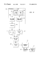
- FIG. 1 is a simplified block diagram of one embodiment of a first computer system that cooperates with one embodiment of an information embedder of the present invention, one embodiment of a second computer system that cooperates with one embodiment of an information extractor of the present invention, and a communication channel coupling the two computer systems;
- FIG. 2 is a functional block diagram of one embodiment of the first and second computer systems of FIG. 1, including one embodiment of the information embedder and information extractor of the present invention
- FIG. 3A is a functional block diagram of the information embedder of FIG. 2;
- FIG. 3B is a functional block diagram of the information embedder of FIG. 2, also showing a first type of preprocessing of the host and watermark signals;
- FIG. 3C is a functional block diagram of the information embedder of FIG. 2, also showing a second type of preprocessing of the host and watermark signals;
- FIG. 3D is a functional block diagram of the information embedder of FIG. 2, also showing a third type of preprocessing of the host and watermark signals;
- FIG. 3E is a functional block diagram of the information embedder of FIG. 2, also showing conventional embedding of a composite signal generated by the information embedder of FIG. 2 :
- FIG. 3F is a functional block diagram of the information embedder of FIG. 2, also showing a fourth type of preprocessing of the host and watermark signals;
- FIG. 3G is a functional block diagram of the information embedder of FIG. 2, also showing a fifth type of preprocessing of the host and watermark signals;
- FIG. 4A is a graphical representation of an illustrative example of a host signal into which a watermark signal is to be embedded by the information embedder of FIGS. 2 and 3;
- FIG. 4B is a graphical representation of an illustrative example of a watermark signal to be embedded in the host signal of FIG. 4A by the information embedder of FIGS. 2 and 3;
- FIG. 5A is a graphical representation of a real-number line with respect to which a known technique for simple quantization may be applied;
- FIG. 5B is a graphical representation of a real-number line with respect to which a known technique for low-bit modulation may be applied;
- FIG. 5C is a graphical representation of a real-number line with respect to which a first embodiment of an ensemble of two dithered quantizers generates one embodiment of dithered quantization values in accordance with the operations of one embodiment of a quantizer ensemble designator of the information embedder of FIG. 3A;
- FIG. 5D is an alternative graphical representation of the real-number line of FIG. 5C;
- FIG. 6A is a graphical representation of a real-number line with respect to which a second embodiment of an ensemble of two dithered quantizers has generated one embodiment of dithered quantization values in accordance with the operations of one embodiment of a quantizer ensemble designator of the information embedder of FIG. 3A;
- FIG. 6B is a graphical representation of a real-number line with respect to which one embodiment of an ensemble of two embedding generators, which are not dithered quantizers, have generated one embodiment of embedding values in accordance with the operations of one embodiment of a quantizer ensemble designator of the information embedder of FIG. 3A;
- FIG. 6C is a graphical representation of a real-number line with respect to which one embodiment of an ensemble of two embedding generators, which are super-rate quantizers, have generated one embodiment of embedding values in accordance with the operations of one embodiment of a quantizer ensemble designator of the information embedder of FIG. 3A; shows one embodiment in which an embedding generator generates embedding values based on a super-rate quantization technique.
- FIG. 7 is a functional block diagram of one embodiment of an ensemble designator of the information embedder of FIG. 3;
- FIG. 8A is a graphical representation of one illustrative example of two-dimensional watermarking of an exemplary host signal with an exemplary watermark signal in accordance with the operations of one embodiment of an ensemble designator of the information embedder of FIG. 3A;
- FIG. 8B is a graphical representation of another illustrative example of two-dimensional watermarking of an exemplary host signal with an exemplary watermark signal in accordance with the operations of one embodiment of an ensemble designator of the information embedder of FIG. 3A;
- FIG. 8C is a graphical representation of one illustrative example of distortion compensation of the exemplary composite signal of FIG. 8A in accordance with the operations of one embodiment of a distortion compensator of the information embedder of FIG. 3A;
- FIG. 9 is a functional block diagram of one embodiment of a distortion compensator of the information embedder of FIG. 3A;
- FIG. 10 is a functional block diagram of the information extractor of FIG. 2;
- FIG. 11 is a graphical representation of one illustrative example of two-dimensional extracting of an exemplary watermark signal from an exemplary host signal in accordance with the operations of one embodiment of a point decoder of the information extractor of FIG. 10 .
- Embedder-extractor 200 embeds watermark signal 102 into host signal 101 to generate composite signal 103 , optionally enables composite signal 103 to be transmitted over communication channel 115 that may include channel noise 104 , and optionally extracts reconstructed watermark signal 106 from the transmitted composite signal.
- Communication channel means any medium, method, or other technique for transferring information, including transferring information to another medium or using a storage device or otherwise.
- the term “communication channel” thus is more broadly applied in this description of the present invention than may typically be used in other contexts.
- “communication channel” as used herein may include electromagnetic, optical, or acoustic transmission mediums; manual or mechanical delivery of a floppy disk or other memory storage device; providing a signal to, or obtaining a signal from, a memory storage device directly or over a network; and using processes such as printing, scanning, recording, or regeneration to provide, store, or obtain a signal. Signal processing may take place in the communication channel.
- a signal that is “transmitted” from an embedding computer system may be processed in accordance with any of a variety of known signal processing techniques before it is “received” by an extracting computer system.
- an audio signal may be modulated in accordance with any of a variety of known techniques, such as frequency modulation, or techniques to be developed in the future.
- the term “transmitted” is used broadly herein to refer to any technique for providing a composite signal and the term “received” is used broadly herein to refer to any technique for obtaining the transmitted composite signal.
- Composite signal is a signal including a host signal, and a watermark signal embedded in the host signal.
- Co-processed group of components of a watermark signal means components of a watermark signal that are together embedded in one or more host signal components, such host signal components being used to embed such co-processed group of components, and no other components of the watermark signal.
- a watermark signal may consist of four bits, the first two of which are together embedded (co-processed) in any number of pixels of a host signal image, and the remaining two of which are together embedded (co-processed) in any number of pixels of the host signal image.
- Doubled quantization value means a value generated by a dithered quantizer.
- a dithered quantization value may be a scalar, or a vector, value.
- Displaced quantizer means a type of embedding generator that generates one or more uniquely mapped, dithered quantization values. Further, each of the dithered quantization values generated by any one of an ensemble of two or more dithered quantizers differs by an offset value (i.e., are shifted) from corresponding dithered quantization values generated by each other dithered quantizer of the ensemble. These dithered quantization values may also be non-intersecting.
- End of embedding generators means two or more embedding generators, each corresponding to one, and only one, of the potential watermark-signal values of a co-processed group of components of a watermark signal.
- Embedding generator means a list, description, table, formula, function, or other generator or descriptor that generates or describes embedding values.
- An illustrative example of an embedding generator is a dithered quantizer.
- Embedding interval for a particular embedding value for a particular embedding generator is the set of host-signal values for which the embedding generator selects the embedding value as the composite-signal value.
- Embedding value means a value generated, described, or otherwise specified or indicated (hereafter, simply “generated”) by an embedding generator.
- An embedding value may be a scalar, or a vector, value.
- “Distortion-compensated embedding value” means a value generated by a distortion compensator.
- a distortion-compensated embedding value may be a scalar, or a vector, value.
- “Host signal” means a signal into which a watermark signal is to be embedded.
- “Host-signal component” means a digital, digitized, or analog elemental component of the host signal.
- one host-signal component is one of the 65,536 pixels of the host signal picture.
- “Host-signal value” means a value of one host-signal component; for example, the grey-scale value of one of the 65,536 pixels of the illustrative host signal picture.
- the host-signal value may be a scalar, or a vector, value. With respect to a vector value, the host-signal value may be, for example, a vector having a length that represents the RGB (red-green-blue) value of one or more pixels of an image.
- Other types of values of host-signal components include color; measures of intensity other than the illustrative grey-scale; texture; amplitude; phase; frequency; real numbers; integers; imaginary numbers; text-character code; parameters in a linear or non-linear representation of the host signal, and so on.
- Noise means distortions or degradations that may be introduced into a signal, whatever the source or nature of the noise.
- Some illustrative sources of noise include processing techniques such as lossy compression (e.g., reducing the number of bits used to digitally represent information), re-sampling, under-sampling, over-sampling, format changing, imperfect copying, re-scanning, re-recording, or additive combinations of signals; channel noise due to imperfections in the communication channel such as transmission loss or distortion, geometric distortion, warping, interference, or extraneous signals entering the channel; and intentional or accidental activities to detect, remove, change, disrupt, or in any way affect the signal.
- the term “noise” thus is more broadly applied in this description of the present invention than may typically be used in other contexts.
- Non-intersecting embedding generator ensemble means an ensemble of embedding generators that generate non-intersecting embedding values.
- One embodiment of a non-intersecting embedding generator ensemble is an ensemble of non-intersecting dithered quantizers.
- Non-intersecting embedding values means that no two or more embedding values generated by any of an ensemble of embedding generators are the same.
- One embodiment of non-intersecting embedding values are non-intersecting dithered quantization values generated by dithered quantizers.
- Non-intersecting distortion-compensated embedding values means that the sets of distortion compensated embedding values corresponding to an ensemble of embedding generators do not contain any elements in common.
- “Signal” means analog and/or digital information in any form whatsoever, including, as non-limiting examples: motion or still film; motion or still video, including, for example, high-definition television; print media; text and extended text characters; projection media; graphics; audio; modulated audio, such as frequency-modulated audio; paging signals; sonar; radar; x-ray; MRI and other medical images; database; data; identification number, value, and/or sequence; and a coded or transformed version of any of the preceding, including, for example, an encrypted version.
- a signal may have any form, including spectral, temporal, or spatial forms. These forms need not be continuous.
- a signal may be a train of spikes wherein the amplitudes of and/or intervals between spikes contain information, or the signal may be a point process.
- Transmit means to enable a signal (typically, a composite signal) to be transferred from an information embedding system to an information extracting system over a communication channel.
- a signal typically, a composite signal
- “Uniquely mapped dithered quantization value” is one example of a uniquely mapped embedding value that is generated by an embedding generator that is a dithered quantizer.
- Uniquely mapped embedding value means that each embedding generator corresponds to one, and only one, watermark-signal value of any of a co-processed group of components of a watermark signal, and that no one of the embedding values generated by such embedding generators is the same as any other embedding value generated by such embedding generators.
- Watermark signal means a signal to be embedded in a host signal.
- an 8-bit identification number may be a watermark signal to be embedded in a host signal, such as the illustrative 256 ⁇ 256 pixel picture.
- a watermark signal need not be an identification number or mark, but may be any type of signal whatsoever.
- the term “watermark” is used more broadly herein than in some other applications, in which “watermark” refers generally to identification marks.
- a watermark signal need not be a binary, or other digital, signal. It may be an analog signal, or a mixed digital-analog signal.
- a watermark signal also may have been subject to error-correction, compression, transformation, or other signal processing, such as encryption.
- the watermark signal may also be determined, in whole or in part, based on the host signal. Such dependence may occur, for example, in an application in which watermarking provides authentication of a signal, as when a digital signature is derived from the host signal and embedded therein, and the extracted digital signature is compared to a signature that is similarly derived from the host signal.
- Watermark-signal component means a digital, digitized, or analog elemental component of the watermark signal.
- the watermark signal is an 8-bit identification number
- one watermark-signal component is one bit of the 8-bits.
- Watermark-signal value means one of a set of two or more potential values of a watermark-signal component or of a co-processed group of watermark-signal components. That is, such value may be a scalar or a vector value.
- watermark-signal values include either the value “0” or “1” of the illustrative one bit of the 8-bit watermark identification signal, or the values “00,” “01,” “10,” or “11” of a co-processed two bits of such signal.
- the watermark-signal value may be, for example, a vector having a length that represents the RGB value of one or more components of the watermark signal.
- watermark-signal components include color; intensity; texture; amplitude; phase; frequency; real numbers; other integers; imaginary numbers; text-character code; parameters of a linear or non-linear representation of the watermark signal; and so on.
- a watermark-signal component has two or more potential watermark-signal values, it will be understood that the value of such component need not vary in a particular application.
- the first bit of the illustrative 8-bit watermark identificationsignal may generally, or invariably, be set to “0” in a particular application.
- Embedder-extractor 200 includes information embedder 201 and information extractor 202 .
- Information embedder 201 generates an ensemble of embedding generators that produce embedding values, each such embedding generator corresponding to a possible value of a co-processed group of components of a watermark signal.
- the embedding generators are dithered quantizers, and the embedding values thus are dithered quantization values.
- Information embedder 201 also changes selected values of the host signal to certain dithered quantization values, thereby generating a composite signal.
- Such dithered quantization values are those generated by the particular dithered quantizer of the ensemble of dithered quantizers that corresponds to the value of the portion of the watermark signal that is to be embedded.
- the composite signal may be provided to a transmitter for transmission over a communication channel.
- the dithered quantization values to which information embedder 201 changes selected values of the host signal are those that are closest to the host-signal values, thereby satisfying one or more distortion criteria.
- members of a first super-group of dithered quantization values to which information embedder 201 changes selected values of the host signal in order to embed a first value of a co-processed group of components of a watermark signal are those that are furthest from members of a corresponding second super-group of dithered quantization values to which information embedder 201 changes selected values of the host signal in order to embed a second value of the co-processed group of components of the watermark signal.
- the first and second super-groups are those that are closest of respective ensembles of super-groups to the corresponding host-signal values, thereby satisfying one or more distortion criteria.
- super-rate quantization is one implementation of what is referred to herein as “adaptive embedding.”
- An adaptive embedding technique is one in which embedding values are generated, or selected, at least in part on the basis of a history of the embedding process. That is, the observed behavior of a host signal is used to predict future behavior, and this predicted future behavior is used, at least in part, to change, supplement, or replace embedding values.
- Information embedder 201 may also compensate for distortion caused by the watermark-embedding process. More specifically, information embedder 201 , in some implementations, generates a scaled difference signal based on a composite signal and host signal, and combines this scaled difference signal with the composite signal to generate a distortion-compensated composite signal. This distortion-compensated composite signal may be provided to a transmitter, and optionally a pre-transmission processor, for transmission over a communication channel.
- Information extractor 202 receives the received composite signal with channel noise and other noise, if any. Information extractor 202 synchronizes such composite signal so that the location of particular portions of such signal may be determined. Information extractor 202 also replicates the ensemble of embedding generators and embedding values that information embedder 201 generated. Such replication may be accomplished in one embodiment by examining a portion of the received signal. In alternative embodiments, the information contained in the quantizer specifier may be available a priori to information extractor 202 . The replicated embedding generators of the illustrated embodiment are dithered quantizers, and the embedding values are dithered quantization values. Further, for each co-processed group of components of the watermark signal, information extractor 202 determines the closest dithered quantization value to received values of selected components of the host signal, thereby reconstructing the watermark signal.
- Embedder-extractor 200 is an illustrative embodiment that is implemented on two computer systems linked by the transmitter, communication channel, and receiver.
- One computer system is used with respect to embedding the watermark, and the other is used with respect to extracting the watermark.
- embedder-extractor may be implemented in software, firmware, and/or hardware. It will be understood, however, that many other embodiments are also possible. For example, both the embedding and extracting functions may be performed on the same computer system; or either or both of such functions may be implemented in hardware without the use of a computer system. It will also be understood that the embedding function may be performed in some embodiments, but not the extracting function, or vice versa.
- a communication channel may not be material in some embodiments.
- functional modules generally are described in terms of software implementations. Such references therefore will be understood typically to comprise sets of software instructions that cause described functions to be performed.
- embedder-extractor 200 as a whole may be referred to as “a set of embedder-extractor instructions.”
- embedder-extractor 200 of the illustrated software implementation typically are performed by a processor such as a special-purpose microprocessor or digital signal processor, or by the central processing unit (CPU) of a computer system.
- a processor such as a special-purpose microprocessor or digital signal processor, or by the central processing unit (CPU) of a computer system.
- CPU central processing unit
- the fact of such cooperation between any of such processor and the modules of the invention, whether implemented in software, hardware, firmware, or any combination thereof, may therefore not be repeated or further described, but will be understood to be implied.
- the cooperative functions of an operating system if one is present, may be omitted for clarity as they are well known to those skilled in the relevant art.
- FIG. 1 is a simplified block diagram of an illustrative embodiment of two computer systems 11 A and 11 B (generally and collectively referred to as computer systems 110 ) with respect to which an illustrative embodiment of embedder-extractor 200 is implemented.
- information embedder 201 is implemented using computer system 110 A (such computer system thus referred to for convenience as an embedding computer system), and information extractor 202 is implemented using computer system 110 B (referred to for convenience as an extracting computer system).
- information embedder 201 and information extractor 202 may be implemented in a special-purpose microprocessor, a digital signal processor, or other type or processor.
- embedding computer system 110 A is coupled to transmitter 120 , which transmits a signal over communication channel 115 for reception by receiver 125 .
- Extracting computer system 110 B is coupled to receiver 125 .
- Computer systems 110 thus are coupled by transmitter 120 , communication channel 115 , and receiver 125 .
- transmitter 120 and a communication channel may couple embedding computer system 110 A to many extracting computer systems.
- such communication channel may be a network, or a portion of the electromagnetic spectrum used for television or radio transmissions, and any number of computer systems may be coupled to the channel either for transmission, reception, or both.
- the term “communication channel” is used broadly herein, and may include the providing or obtaining of information to or from a floppy disk, a graphical image on paper or in electronic form, any other storage device or medium, and so on.
- the providing or obtaining of information to or from the communication may include various known forms of signal processing.
- FIG. 2 is a simplified functional block diagram of an illustrative embodiment of computer systems 110 , including embedder-extractor 200 .
- Each of computer systems 110 may include a personal computer, network server, workstation, or other computer platform now or later developed. Computer systems 110 may also, or alternatively, include devices specially designed and configured to support and execute the functions of embedder-extractor 200 , and thus need not be general-purpose computers.
- Each of computer system 110 A and computer system 110 B may include known components such as, respectively, processors 205 A and 205 B, operating systems 220 A and 220 B, memories 230 A and 230 B, memory storage devices 250 A and 250 B, and input-output devices 260 A and 260 B. Such components are generally and collectively referred to as processors 20 S, operating systems 220 , memories 230 , memory storage devices 250 , and input-output devices 260 .
- Such transmitting or receiving devices may employ analog, digital, or mixed-signal processing of any type, including encoding/decoding, error detection/correction, encryption/decryption, other processing, or any combination thereof.
- Such devices may employ any of a variety of known modulation and other techniques or processes, such as amplitude modulation or frequency modulation, or various types of digital modulation such as uncoded pulse-amplitude modulation (PAM), quadrature-amplitude modulation (QAM), or phase-shift keying (PSK); coded PAM, QAM, or PSK employing block codes or convolutional codes; any combination of the preceding; or a technique or process to be developed in the future.
- PAM pulse-amplitude modulation
- QAM quadrature-amplitude modulation
- PSK phase-shift keying
- pre-processors 109 A- 109 F (generally and collectively referred to herein as pre-processors 109 ), and post-processor 111 may be included in computer systems 110 A and 110 B, respectively.
- Processors 205 may be commercially available processors such as a Pentium processor made by Intel, a PA-RISC processor made by Hewlett-Packard Company, a SPARC® processor made by Sun Microsystems, a 68000 series microprocessor made by Motorola, an Alpha processor made by Digital Equipment Corporation, or they may be one of other processors that are or will become available.
- a digital signal processor such as a TMS320-series processor from Texas Instruments, a SHARC processor from Analog Devices, or a Trimedia processor from Phillips, may be used.
- Processors 205 execute operating systems 220 , which may be, for example, one of the DOS, Windows 3.1, Windows for Work Groups, Windows 95, Windows NT, or Windows 98 operating systems from the Microsoft Corporation; the System 7 or System 8 operating system from Apple Computer; the Solaris operating system from Sun Microsystems; a Unix®-type operating system available from many vendors such as Sun Microsystems, Inc., Hewlett-Packard, or AT&T; the freeware version of Unix® known as Linux; the NetWare operating system available from Novell, Inc.; another or a future operating system; or some combination thereof.
- Operating systems 220 interface with firmware and hardware in a well-known manner, and facilitate processors 205 in coordinating and executing the functions of the other components of computer systems 110 .
- either or both of operating system 220 need not be present.
- Either or both of computer systems 110 may also be one of a variety of known computer systems that employ multiple processors, or may be such a computer system to be developed in the future.
- Memories 230 may be any of a variety of known memory storage devices or future memory devices, including, for example, any commonly available random access memory (RAM), magnetic medium such as a resident hard disk, or other memory storage device.
- Memory storage devices 250 may be any of a variety of known or future devices, including a compact disk drive, a tape drive, a removable hard disk drive, or a diskette drive. Such types of memory storage devices 250 typically read from, and/or write to, a program storage device (not shown) such as, respectively, a compact disk, magnetic tape, removable hard disk, or floppy diskette. Any such program storage device may be a computer program product. As will be appreciated, such program storage devices typically include a computer usable storage medium having stored therein a computer software program and/or data.
- Computer software programs also called computer control logic, typically are stored in memories 230 and/or the program storage devices used in conjunction with memory storage devices 250 . Such computer software programs, when executed by processors 205 , enable computer systems 110 to perform the functions of the present invention as described herein. Accordingly, such computer software programs may be referred to as controllers of computer systems 110 .
- the present invention is directed to a computer program product comprising a computer usable medium having control logic (computer software program, including program code) stored therein.
- the control logic when executed by processors 205 , causes processors 205 to perform the functions of the invention as described herein.
- the present invention is implemented primarily in hardware using, for example, a hardware state machine. Implementation of the hardware state machine so as to perform the functions described herein will be apparent to those skilled in the relevant arts.
- Input devices of input-output devices 260 could include any of a variety of known devices for accepting information from a user, whether a human or a machine, whether local or remote. Such devices include, for example a keyboard, mouse, touch-screen display, touch pad, microphone with a voice recognition device, network card, or modem.
- Output devices of input-output devices 260 could include any of a variety of known devices for presenting information to a user, whether a human or a machine, whether local or remote. Such devices include, for example, a video monitor, printer, audio speaker with a voice synthesis device, network card, or modem.
- Input-output devices 260 could also include any of a variety of known removable storage devices, including a compact disk drive, a tape drive, a removable hard disk drive, or a diskette drive.
- host signal 101 and watermark signal 102 typically are loaded into computer system 110 A through one or more of the input devices of input-output devices 260 A.
- signals 101 and/or 102 may be generated by an application executed on computer system 110 A or another computer system (referred to herein as “computer-generated” signals).
- Received composite signal with noise 105 typically is acquired by receiver 125 and loaded into computer system 110 B through one or more of the input devices of input-output devices 260 B.
- reconstructed watermark signal 106 typically is output from computer system 110 B through one or more of the output devices of input-output devices 260 B.
- Computer system 110 A typically is coupled to transmitter 120 through one or more output devices of input-output devices 260 A, and computer system 110 B typically is coupled to receiver 125 through one or more input devices of input-output devices 260 B. Further, in some embodiments, received composite signal with noise 105 and reconstructed watermark signal 106 may be provided to post-processor 111 for post-processing.
- Embedder-extractor 200 could be implemented in the “C” or “C++” programming languages, or in an assembly language. It will be understood by those skilled in the relevant art that many other programming languages could also be used. Also, as noted, embedder-extractor 200 may be implemented in any combination of software, hardware, or firmware. For example, it may be directly implemented by micro-code embedded in a special-purpose microprocessor, If implemented in software, embedder-extractor 200 may be loaded into memory storage devices 250 through one of input-output devices 260 . All or portions of embedder-extractor 200 may also reside in a read-only memory or similar device of memory storage devices 250 , such devices not requiring that embedder-extractor 200 first be loaded through input-output devices 260 . It will be understood by those skilled in the relevant art that embedder-extractor 200 , or portions of it, may typically be loaded by processors 205 in a known manner into memories 230 as advantageous for execution.
- information embedding computer system 110 A operates upon host signal 101 and watermark signal 102 . These signals may be pre-processed, as indicated in FIGS. 1 and 2 by pre-processor 109 . More generally, computer system 110 A, and information embedder 201 in particular, may operate on various embodiments of host signals and/or watermark signals resulting from various pre-processing functions, illustrative examples of which are shown in FIGS. 3B-3D, 3 F, and 3 G.
- FIG. 3E shows a related system that includes post-processing of composite signal 332 of the present invention by a conventional embedding system. (For clarity, the functional blocks of information embedder 201 are not shown in FIGS.
- a host signal i.e., host signals 101 , and 101 A- 101 G
- host signals 101 i.e., host signals 101 , and 101 A- 101 G
- watermark signals 102 various illustrative embodiments of a watermark signal, i.e., watermark signals 102 , and 102 A- 102 G, are generally and collectively referred to herein as watermark signals 102 .
- host signals 101 and watermark signals 102 are exemplary and that many other embodiments are possible, including those not shown in FIGS. 3A-3G.
- host signals 101 and/or watermark signals 102 may be pre-processed in any of a variety of ways, such as being transformed, encoded, encrypted, smoothed, or interleaved.
- Interleaving is a form of scrambling, as is well known to those skilled in the relevant art.
- a process commonly known as discrete cosine transformation may have been applied to a host signal that is an image.
- transformations are Fourier, Fourier-Mellin, or Radon, transforms; JPEG or MPEG compression; wavelet transformation; or lapped orthogonal transformation.
- conventional embedding techniques, or others to be developed in the future may be applied to pre-process a host signal or watermark signal.
- many combinations of these transformations are possible; e.g., a host signal subject to a Fourier-Mellin transform may be encrypted. Any other of many known techniques or processes, or others to be developed in the future, may have been applied by various pre-processing modules, whether or not shown in FIGS. 3A-3G, to produce host signals 101 and/or watermark signals 102 .
- transformed and its grammatical variants is hereafter used broadly to refer to any of these known, or later-to-be-developed, techniques or operations, or combinations thereof, by which a host signal or watermark signal is pre-processed.
- pre-processors 109 B- 109 D, 109 F, and 109 G are respectively carried out in these figures by pre-processors 109 B- 109 D, 109 F, and 109 G, generally and collectively referred to hereafter as pre-processors 109 .
- Pre-processors 109 operate upon exemplary audio signals 360 B- 360 D, 360 F, and 360 G, generally and collectively referred to as audio signals 360 .
- Audio signals 360 may be, for example, music or voice from a microphone or recording-playback device (not shown), typically in the human auditory frequency range. It will be understood that many other types of signals may be pre-processed in the manners described with respect to FIGS. 3B-3G.
- audio signals 360 in alternative embodiments, could be television video signals, paging signals, one or both signals of separate stereo audio channels, or audio signals outside the range of human hearing.
- audio signals 360 are also referred to herein more broadly as “primary signals” to indicate that any type of signal may be operated upon by pre-processors 109 .
- Audio signal is used for convenience with respect to some illustrated embodiments described below, rather than the broader term “primary signals,” because these embodiments involve exemplary applications in which signals in the audio and FM domains are employed.
- Audio signals 360 may be externally selected by a user, they may be signals generated by a computer or another device, or they may be made available for processing by pre-processors 109 in accordance with any other known technique or one to be developed in the future.
- FIG. 3B is a functional block diagram of information embedder 201 that operates upon host signal 101 B and watermark signal 102 B, as those signals are pre-processed by pre-processor 109 B.
- the system schematically shown in FIG. 3B also includes modulator 355 B.
- modulators 355 including modulator 355 B, is an FM modulator.
- modulators 355 may be any type of modulator, including an amplitude modulator, a digital modulator, or any other kind of modulator whatsoever. It is illustratively assumed with respect to the embodiment of FIG. 3B that it is desirable that audio signal be available in two different formats.
- the term “format” refers broadly as used hereafter in this context to any one or more criteria or technique for transforming, processing, formatting, or otherwise specifying or providing the form of a signal.
- either or both of host signal 101 B and watermark signal 102 B may be only part of a transformed version of audio signal 360 B. That is, for example, watermark signal 102 B may be only a part of audio signal 360 B in digital format. The remainder of audio signal 360 B in digital format may not be intended to be embedded in host signal 101 B. Rather, it may be transmitted separately, or embedded in some other host signal in some other FM, or other, channel, or not transmitted nor embedded at all.
- audio signal 360 B may, in some implementations, be two different signals.
- a signal 360 B 1 may be transformed by first format transformer 3611 B to generate host signal 1011 B
- a different signal 360 B 2 may be transformed by second format transformer 362 B to generate watermark signal 102 B.
- FIG. 3B reference is made in FIG. 3B to audio signal 360 B, however, it will be understood that it is not necessary that the same signal be provided to generate both the host signal and watermark signal.
- audio signal 360 C of the system of FIG. 3C need not be the same signal with respect to generating the host and watermark signals.
- either host signal 101 B or watermark signal 102 B need not be a transformed audio (or other type of) signal.
- audio signal 360 B 1 could be transformed to generate host signal 101 B
- different signal 360 B 2 which is not an audio signal, could be transformed to generate watermark signal 102 B.
- first format transformer 361 B transforms audio signal 360 B into an analog format and that second format transformer 362 B transforms it into a digital format.
- the resulting transformed signal in analog format constitutes host signal 101 B and that the resulting transformed signal in digital format constitutes watermark signal 102 B, as shown in FIG. 3 B. It would not materially affect the operation of the invention if the opposite were assumed; i.e., if the digital signal were the host signal and the analog signal were the watermark signal.
- Information embedder 201 operates upon host signal 101 B and watermark signal 102 B to generate a composite signal 332 , as shown in FIG. 3 A and described in detail below.
- pre-transmission processor 335 such as shown in FIG. 3A, may also be used in the system of FIG. 3B or any other information embedding system in accordance with the present invention.
- Pre-transmission processor 335 may optionally be used to return composite signal 332 to the original domain of audio signals 360 .
- transformer 361 B or transformer 362 B may have been used to transform audio signals 360 B by using a Fourier, Fourier-Mellin, Radon, or other transform.
- Pre-transmission processor 335 may advantageously be used in some implementations to return composite signal 332 to the audio domain rather than the Fourier, Fourier-Mellin, or Radon domain.
- This process referred to for convenience here as a domain inversion, may be accomplished in accordance with any of a variety of known techniques such as using an inverse Fourier, inverse Fourier-Mellin, or inverse Radon transformation, respectively.
- Composite signal 332 may be transmitted, such as over communication channel 115 by transmitter 120 , or it may first be further processed.
- the illustrative embodiment of FIG. 3B includes further processing by frequency modulation of the output of information embedder 201 ; i.e., frequency modulation of composite signal 332 by modulator 355 B.
- frequency modulation could be accomplished by appropriate known circuitry included in transmitter 120 .
- transmitted composite signal 103 B is a signal in the modulation domain that, in accordance with known techniques, may be demodulated by an appropriate demodulator (not separately shown).
- the demodulator may be included, for example, in receiver 125 as shown in FIGS. 1 and 2.
- post-receiver signal 105 A shown in FIG. 2 (and in FIG. 10, described below with respect to the operations of information extractor 202 ), is a signal that has been demodulated from the modulation domain to the audio domain in this example.
- reconstructed watermark signal 106 is extracted from post-receiver signal 105 A to provide a reconstruction of audio signal 360 B in a digital format.
- post-receiver signal 105 A is approximately equivalent to audio signal 360 B in an analog format, as distorted by the embedding process of embedder 201 , described below, channel noise, and possibly other factors.
- Reconstructed watermark signal 106 may thus be provided to an audio-processing device, such as an amplifier, that operates on digital audio signals.
- Post-receiver signal 105 A may similarly be provided to an amplifier, or other audio-processing device, that operates on analog audio signals.
- the bandwidth of transmitted composite signal 103 B generally need not be greater than the bandwidth required to transmit host signal 101 B, as will be evident to those skilled in the relevant art in view of the description below of the operations of embedder 201 .
- This capability to transmit all, or part, of both analog and digital representations of the same audio signal, over the same communication channel and generally within the same bandwidth, is advantageously employed in various commercial situations.
- a regulatory environment may pertain in which simultaneous, in-band, on-channel, transmission of an FM signal in an older, analog, format and also in a newer, digital, format is required.
- older FM receivers designed to process signals in the analog format will not be made obsolete, yet new FM receivers designed to process signals in the digital format will be able to operate.
- the same advantage may be obtained with respect to the simultaneous transmission, as a further illustrative and non-limiting example, of analog and digital television signals.
- frequency modulation may protect the composite signal from channel noise in accordance with techniques and effects known to those skilled in the relevant art.
- frequency modulation may protect the composite signal from channel noise in accordance with techniques and effects known to those skilled in the relevant art.
- the protective effects of frequency modulation on the composite signal may not fully be realized.
- alteration of the frequency-modulated host signal by embedding of a watermark signal may influence the ability of the FM demodulator to decode the FM signal.
- the system of FIG. 3B thus may reduce the need to consider the parameters of operation of the FM demodulator with respect to specifying permissible limits on distortion introduced by the embedding process.
- FIG. 3C is a functional block diagram of information embedder 201 that operates upon host signal 101 C and watermark signal 102 C, as those signals are pre-processed by pre-processor 109 C.
- first format transformer 361 C transforms audio signal 360 C into a first format that may be, for example, an analog format. This analog signal is then FM modulated by modulator 355 C to provide host signal 101 C.
- this FM-modulated signal could be provided as watermark signal 102 C.
- second format transformer 362 C transforms audio signal 360 C into a second format that may be, for example, a digital format.
- watermark signal 102 C is this transformed audio signal in digital format.
- Watermark signal 102 C is embedded into host signal 101 C in accordance with the operations of embedder 201 described below.
- embedding occurred in the audio domain and frequency modulation (by modulator 355 B) was applied to the resulting composite signal.
- embedding occurs in the modulation domain because host signal 101 C is modulated by modulator 355 C.
- transmitted composite signal 103 B of FIG. 3B transmitted composite signal 103 C of the system of FIG. 3C is in the modulation domain.
- receiver 125 typically does not include a demodulator. Rather, post-receiver signal 105 A, as shown in FIG.
- Post-processor 111 typically includes a demodulator (not separately shown) that demodulates post-receiver signal 105 A to generate an approximation of audio signal 360 C as transformed by first format transformer 361 C (i.e., in an analog format) and as distorted by the embedding process, channel noise, and possibly other factors.
- a demodulator not separately shown
- This potential advantage is due to the fact that FM demodulation may suppress aspects of the distortion introduced by the embedding process of embedder 201 , for reasons that are known to those skilled in the relevant art.
- Information extractor 202 operates upon post-receiver signal 105 A (which, as noted, is in the modulation domain), as described below, to generate reconstructed watermark signal 106 . Because watermark signal 102 C is a digital signal in the audio domain, reconstructed watermark signal 106 also is a digital signal in the audio domain. Reconstructed watermark signal 106 may thus be provided directly to a digital amplifier, or another known or to-be-developed audio-processing device that operates on digital audio signals. This audio-processing device is not separately shown, but is considered to be part of post-processor 111 .
- FIG. 3D is a functional block diagram of information embedder 201 that operates upon host signal 101 D and watermark signal 102 D, as those signals are pre-processed by pre-processor 109 D. It is illustratively assumed with respect to the system of FIG. 3D that it is desired that supplementary information, represented by supplemental signal 362 D, be embedded in audio signal 360 D. For example, it may be desired that the call letters and frequency of a radio station be provided along with an audio signal to be transmitted by the radio station. It will be understood that the assumptions that the host signal is an audio signal and that the watermark signal is supplementary information are exemplary only. The system and method of FIG. 3D may be applied to any types of signals. For example, signal 360 D may be a television video signal, and supplemental signal 372 D may be captioning information. Or, signal 360 D may be an image, and supplemental signal 372 D may be a digital fingerprint.
- signal 360 D may be a television video signal
- supplemental signal 372 D may be captioning information.
- a conventional, or later-to-be-developed, system or method for embedding a watermark signal in a host signal is employed to embed supplemental signal 362 D in audio signal 360 D to generate conventional or future composite signal 367 D.
- This system or method is represented in FIG. 3D by conventional or future embedder 365 D.
- the term “conventional” in these contexts will hereafter be used to refer to “conventional or future.”
- FIGS. 3E-3G the application of any of a variety of known, or later-to-be-developed watermarking systems or methods is assumed in FIGS. 3E-3G, and these systems or methods are hereafter generally and collectively referred to as conventional embedders 365 .
- Non-limiting examples of conventional embedders 365 include those described in publications 1-9 in the Background section above, and modifications or improvements thereto that now exist or may be made in the future. As will be described below in relation to FIG. 3A, and line 372 in particular, pre-processing of a host signal or watermark signal may also be accomplished using embedder 201 of the present invention in the same manner as conventional embedder 365 D is employed in the system of FIG. 3D and, more generally, in the same manner as any of conventional embedders 365 are employed in the systems of FIGS. 3D-3G.
- embedder 365 D embeds supplemental signal 362 D in audio signal 360 D, nor is the composition of composite signal 367 D material.
- composite signal 367 D is operated upon by embedder 201 as one embodiment of host signals 101 in the same manner as described below with respect to the operations of embedder 201 with respect to host signals 101 generally. That is, host signal 101 D is a signal that has been transformed by a particular technique (the embedding technique of embedder 365 D) and, as noted, the fact that an embodiment of host signals 101 may have been transformed from another signal is not material to the operation of the present invention.
- host signal 101 D of the illustrated embodiment of FIG. 3D is composite signal 367 D.
- watermark signal 102 D is supplemental signal 362 D, as indicated by data-flow line 374 of FIG. 3 D. That is, the same signal (signal 362 D) that was employed as a watermark signal by conventional embedder 365 D is illustratively employed as a watermark signal with respect to the operation of embedder 201 of the present invention. It will be understood that it is not necessary, however, that the same signal be so used. Rather, watermark signal 102 D may be a portion or portions of supplemental signal 362 D, a transformed version of all or parts of it, or another watermark signal (as explicitly shown with respect to the system of FIG. 3 F).
- the illustrated embodiment is intended to represent generally the use of embedder 201 to operate upon a host signal that is itself a composite signal including a watermark signal, which may be the same watermark signal operated upon by embedder 201 .
- the illustrated embodiment is thus referred to as one example of a multiple-embedding system
- This use of the present invention i. e., to embed a watermark signal in a host signal that includes that (or another) watermark signal as embedded by a system or technique other than that of the present invention, may have significant commercial advantages.
- commercial equipment may be in use that implements the conventional embedding system, and the present invention may be used to supplement that existing equipment.
- a conventional embedding system (or one to be developed in the future) may embed supplemental information (such as call letters) into an audio signal.
- the present invention may be used to embed additional information into that composite signal, such as, for example, subtitles, translations, commentary, and so on.
- the present invention may be used to re-embed all or part of the information already embedded by conventional techniques in order to provide error detection and correction, or for other purposes.
- the system shown in FIG. 3E is a multiple-embedding system.
- pre-processing may be considered to be done by the present invention rather than by a conventional embedder.
- the host signal operated upon by conventional embedder 365 E is the output of embedder 201 of the present invention; i.e., composite signal 332 .
- the watermark signal operated upon by embedder 365 E may be the same watermark signal operated upon by embedder 201 , i.e., watermark signal 102 E as shown in FIG. 3E, it may be a portion of signal 102 E, or it may be another watermark signal.
- the system of FIG. 3E provides a commercial advantage similar to that noted with respect to the system of FIG. 3 D. That is, embedder 201 may be used to supplement, replicate, verify, or otherwise augment the embedding process accomplished by conventional embedder 365 E.
- FIG. 3F is a functional block diagram of information embedder 201 that operates upon host signal 101 F and watermark signal 102 F, as those signals are pre-processed by pre-processor 109 F.
- the system of FIG. 3F is also a multiple-embedding system, and is the same as the system described with respect to FIG. 3D except that a different watermark signal is operated upon by conventional embedder 365 F than is operated upon by embedder 201 of the present invention.
- embedder 365 F embeds supplemental signal 362 F in audio signal 360 F, i.e., signal 362 F is a watermark signal.
- audio signal 360 F is available to both information embedding computer system 110 A and information extracting computer system 110 B.
- conventional embedding techniques referred to as “additive” in nature may be used without the disadvantage that the host signal (audio signal 360 F) constitutes additive noise in the composite signal (signal 367 F). That is, the host signal may be subtracted out, in accordance with known techniques, to remove the distortion introduced by the additive embedding technique.
- supplemental signal 362 F may be extracted from conventional composite signal 367 F by a conventional extracting system corresponding to the conventional embedding system of embedder 365 F, and without the adverse effects of additive noise due to audio signal 360 F.
- watermark signal 102 F also be embedded in the composite signal to be transmitted by transmitter 120 , and that a reconstructed watermark signal be extractable without knowledge of host signal 101 F (which, in the system of FIG. 3F, is composite signal 367 F).
- an advantage of embedder 201 of the present invention is that a reconstruction of watermark signal 102 F may be extracted without knowledge of host signal 101 F.
- embedder 201 may be used to embed watermark signal 102 F into composite signal 367 F, which, as noted, already has embedded in it supplemental signal 362 F.
- FIG. 3G is a functional block diagram of information embedder 201 that operates upon host signal 101 G and watermark signal 102 G, as those signals are pre-processed by pre-processor 109 G.
- the system of FIG. 3G is a multiple-embedding system and is the same as the multiple-embedding system of FIG. 3F except that modulator 355 G is included in pre-processor 109 G.
- pre-processor 109 G includes conventional embedder 365 G that embeds supplemental signal 362 G in audio signal 360 G to generate a composite signal that is provided to modulator 355 G.
- Modulator 355 G transforms the composite signal to the modulation domain, as represented by conventional composite signal 367 G.
- Composite signal 367 G thus differs from composite signal 367 F of FIG. 3F in that the former is in the modulation domain, whereas the latter is in the audio domain. Also, whereas embedder 201 in the system of FIG. 3G operates upon host signal 101 G (which is composite signal 367 G) in the modulation domain, conventional embedder 365 G operates on audio signal 360 G and supplemental signal 362 G in the audio domain. Thus, some of the various advantages stated above of operating in the two domains, and of applying a multiple-embedding process, are combined in the system of FIG. 3 G.
- any one of these systems may be combined with one or more features of one or more other of these systems to provide a configuration not explicitly shown in FIGS. 3B-3G. It is intended that all such alternative configurations are to be considered included within the scope of the present invention.
- a type of multiple-embedding configuration is possible in which embedder 201 operates upon a composite signal generated by a conventional embedder, which operates upon a composite signal generated by embedder 201 , and so on.
- FM modulation may be applied at any stage of the multiple-embedding process; e.g., to a host signal operated upon by embedder 201 or a conventional embedder, to a composite signal generated by embedder 201 or a conventional embedder, or to a watermark signal operated upon by embedder 201 or a conventional embedder.
- information embedder 201 embeds watermark signal 102 into host signal 101 to produce composite signal 103 that may be transmitted or otherwise distributed or used. Specifically, with respect to the illustrated embodiment, information embedder 201 generates an ensemble of two or more dithered quantizers that produce dithered quantization values, each such dithered quantizer corresponding to a possible value of a co-processed group of components of a watermark signal. As further noted, information embedder 201 also changes selected values of the host signal to certain dithered quantization values, thereby generating a composite signal. Such dithered quantization values are those generated by the particular dithered quantizer of the ensemble of dithered quantizers that corresponds to the value of the portion of the watermark signal that is to be embedded.
- the dithered quantization values to which information embedder 201 changes selected values of the host signal are those that are closest to the host-signal values, thereby satisfying one or more distortion criteria.
- reliability criteria, as well as distortion criteria are implemented.
- the dithered quantization values to which information embedder 201 changes selected values of the host signal need not be those that are closest to the host-signal values.
- information embedder 201 may also generate a scaled difference signal based on a composite signal and host signal. This scaled difference signal is then combined with the composite signal to generate a distortion-compensated composite signal.
- FIG. 3A is a functional block diagram of information embedder 201 that, as shown, includes host-signal analyzer and block selector 310 , ensemble designator 320 , and point coder 330 .
- embedder 201 may also include distortion compensator 333 that implements distortion compensation, and/or may include pre-transmission processor 335 that implements domain inversions.
- Host-signal analyzer and block selector 310 analyzes host signal 101 to select host-signal embedding blocks in which watermark signal 102 is to be embedded.
- Ensemble designator 320 designates two or more dithered quantizers, one for each possible value of a co-processed group of components of watermark signal 102 A. Each dithered quantizer generates non-intersecting dithered quantization values.
- the dithered quantizers designated by ensemble designator 320 generate dithered quantization values selected in accordance with the maximum allowable watermark-induced distortion level, expected channel-induced distortion level, a desired intensity of a selected portion of the watermark signal in the host-signal embedding blocks, and/or, in the case of super-rate quantization, desired reliability criteria.
- Point coder 330 codes host-signal values of the host-signal components of the selected portions of the host signal in the embedding blocks. Such coding is done in the illustrated embodiment by changing such host-signal values to the closest dithered quantization value.
- Distortion compensator 333 compensates for distortion in the composite signal in accordance with the required minimum number of possible watermark signal values that can be embedded, the maximum desired watermark-induced distortion level, the expected channel-induced distortion level, and the desired reliability of information extractor 202 .
- host-signal analyzer and block selector (hereafter, simply “selector”) 310 operates on host signals 101 .
- host signals 101 are digital signals, which may be digitized versions of analog signals.
- host signals 101 may be analog signals, or combination analog and digital signals.
- Host signals 101 may be pre-processed by pre-processors 109 , may be externally selected by a user and made available for processing by computer system 110 A in accordance with known techniques, or may be a computer-generated signal.
- selector 310 may select host signals 101 by, for example, consulting a look-up table (not shown) of host signals into which watermark signals are to be embedded, or using other techniques.
- Selector 310 optionally selects one or more blocks, generally and collectively referred to as host-signal embedding blocks 312 , from host signal 101 .
- host signal 101 A is a black and white image, a simplified graphical representation of which is shown in FIG. 4 A. It is also so assumed that dimensions 401 and 402 of host signal 101 are each 256 pixels long, i.e., the image of host signal 101 consists of 65,536 pixels. Each of such pixels has a grey-scale value that, in the illustrative example, is a real number. It will be understood that, in other illustrative examples, such grey-scale values may be otherwise represented.
- selector 310 are illustrated with respect to pixels of an image, but embedder-extractor 200 is not so limited.
- a pixel is an illustrative example of what is referred to herein more generally as a host-signal component.
- the grey-scale value of a pixel similarly is an illustrative example of what is referred to herein more generally as a host-signal value.
- Other examples of host-signal values and host-signal components include the RGB (red-green-blue) value of a pixel, the luminance and chrominance values of a pixel, the amplitude or linear predictive coefficient of a speech sample, and so on.
- selector 310 selects blocks of pixels of host signal 101 that are graphically represented by embedding blocks 312 A-C.
- Selector 310 may employ any of a variety of factors in making such selection, some of which factors may depend on the embedding application.
- the application may be one in which an identification number is to be embedded in a particular copy of a copyrighted image so that the identification number may not be removed without compromising the image.
- selector 310 may employ any of a variety of known, or to-be-developed, techniques to determine which regions of host signal 101 contain significant, or significant amounts of, information.
- the watermarks may be said to be “tamper-resistant.” For example, one such technique would be to identify areas in which there is a greater amount of diversity in the grey-scale values of pixels than in other areas.
- tamper resistance may not be an important factor. Rather, it may be desirable to embed the watermark in portions of the host signal that are less important than others, or that may be distorted with less important consequences, even though tampering may thus be made easier.
- the human ear and auditory system of the brain are susceptible to various masking phenomena.
- temporal masking in which a person may be less sensitive to sounds that occur just after, or before, a loud sound.
- the human auditory system is susceptible to spectral masking so that portions of the host signal having certain frequency characteristics may be selected for their masking properties.
- selection with respect to video signals may be made to take advantage of various known masking phenomena associated with the human visual system.
- selection may advantageously be made of portions of a host signal that are relatively less important than others in a particular application. An example is the selection of FM side bands.
- many areas of the electromagnetic spectrum may be relatively less important in certain applications with respect to carrying information, and thus serve as favorable host signals.
- Some examples may include ultra-violet or infra-red frequencies.
- Other examples in an audio context are certain sounds, e.g., animal sounds, thunder, highway noise, etc., the distortion of which may not readily be noticed.
- factors typically employed by selector 310 in selecting portions of host signal 101 for embedding include the amount of information to be embedded; the availability of various resources of computer system 110 A, such as the amount of available memory in memories 230 or the speed of processors 205 ; the desirability of embedding a watermark signal in a location in the host signal that is likely to be subject to tampering (in relation to other locations in the host signal); and the desirability of embedding a watermark signal in a location that is relatively less likely to result in distortion to the host signal or is relatively easier to extract.
- the relevance of such factors is described below with respect to the functions of dimensionality determiner 710 of FIG. 7 .
- selector 310 selects embedding block 312 C.
- selector 310 may select any number of embedding blocks between 1 and 65,536 in the illustrative example; that is, all of host signal 101 may be an embedding block, or each pixel of host signal 101 may be an embedding block.
- the embedding block may be continuing; that is, for example, host signal 101 may include a continuing signal stream into which a watermark signal is embedded at various points in the stream.
- embedding blocks may have any configuration, e.g., they need not be rectangles as shown in FIG. 4, and they need not be contiguous.
- selector 310 identifies those pixels included in embedding block 312 C by determining its boundaries, or other indicator of placement within host signal 101 , such as offset from the beginning of host signal 101 .
- block identification may be used in a known manner to synchronize received composite signal with noise 105 with transmitted composite signal 103 .
- Such synchronization enables information extractor 202 to identify a block of pixels corresponding to embedding block 312 C even if a portion of transmitted composite signal 103 has not been received or is distorted.
- ensemble designator 320 of the illustrated embodiment designates two or more dithered quantizers, one for each possible value of a co-processed group of components of watermark signal 102 .
- a dithered quantizer is a type of embedding generator.
- ensemble designator 320 may designate embedding generators that are not dithered quantizers.
- FIG. 4B is one illustrative embodiment of watermark signal 102 that is an eight-bit message; for example, a binary serial number.
- a binary serial number There are thus 256 possible serial numbers.
- such illustrative serial numbers may be the binary numbers themselves, or the binary numbers may represent numbers, text, or other representations contained in a look-up table, or other data structure, indexed by the binary numbers or related pointers.
- the bits of the illustrative serial number are labeled 451 - 458 , with bit 451 being the most significant bit (or “high” bit), and bit 458 being the least significant bit (or “low” bit).
- Each of bits 451 - 458 is a component of watermark signal 102 .
- each component may thus have one of two watermark-signal values, typically 0 or 1.
- Watermark signal 102 may be a transformed, coded, encrypted, or otherwise processed, version of an original watermark signal (not shown).
- bits 451 - 458 of exemplary watermark signal 102 of FIG. 4B may constitute parity bits, or other error-detection bits, that have been added to an original watermark signal by an error-detection/error-correction device (not shown).
- watermark signal 102 in alternative examples need not be a binary, or other digital, signal. It may be an analog signal, or a mixed digital-analog signal.
- Each dithered quantizer generates non-intersecting and uniquely mapped dithered quantization values.
- One “one-dimensional” implementation of the generation of such dithered quantization values is shown in FIG. 5 C.
- the term “one-dimensional” means in this context that a watermark-signal component, or group of co-processed watermark-signal components, is embedded in one host-signal component, i.e., one pixel in the illustrated embodiment.
- the term “two-dimensional” is used herein, for example with respect to FIGS. 8A and 8B, to mean that a watermark-signal component, or group of co-processed watermark-signal components, is embedded in two host-signal components, i. e., two pixels in the illustrated embodiment.
- the number of dimensions may be any integer up to the number of host signal components in the host-signal embedding block (or in the host signal, if there is only one such block constituting the entire host signal).
- any one (or any combination, as noted below) of bits 451 - 458 may be embedded in one, two, or any integer up to 65,536, pixel(s) of host signal 101 of FIG. 4 A.
- more than one watermark-signal component i.e., more than one bit in the illustrative example
- two bits may be embedded in two pixels. Watermark-signal components thus embedded together in one or more host signal components are referred to as a group of co-processed watermark-signal components.
- FIGS. 5A-D and FIGS. 6A and 6B show illustrative examples of quantization (FIG. 5 A), quantization and low-bit modulation (FIG. 5 B), the generation of quantization values using dithered quantization (FIGS. 5C, 5 D, and 6 A), the generation of embedding values using an embedding generator that is not a dithered quantizer (FIG. 6 B), and super-rate quantization (FIG. 6 C). More specifically, FIG. 5A is a graphical representation of real-number line 501 with respect to which is illustrated the simple quantization of a real number using a known technique. FIG.
- FIG. 5B is a graphical representation of real-number line 502 upon which is illustrated the quantization and modulation of a real number using the known technique of low-bit modulation.
- FIG. 5C is a graphical representation of real-number line 503 upon which is illustrated the dithered quantization of a host-signal value, i.e., the embedding of a watermark-signal component using one embodiment in which a pair of dithered quantizers are employed in accordance with the present invention.
- FIG. 5D is an alternative graphical representation of real-number line 503 of FIG. 5 C.
- FIG. 6A similarly shows the operations of a pair of dithered quantizers in accordance with the present invention, except that whereas the quantization values generated by each of the dithered quantizers of FIGS. 5C and 5D are regularly and evenly spaced, such regularity is not present with respect to the quantization values of FIG. 6 A.
- FIG. 6B shows the operations of a pair of embedding generators in accordance with the present invention that are not dithered quantizers.
- the Simple Quantizer of FIG. 5 A The simple quantization technique illustrated in FIG. 5A is used to quantize a real number to an integer so that, for example, it may be represented by a binary number. Such quantization and binary representation commonly are done to facilitate digital storage, manipulation, or other processing of the host signal that requires, or benefits from, the use of binary numbers rather than real numbers. Such simple quantization is not a watermarking technique because it does not embed a watermark signal in a host signal. However, some of the terms applicable to watermarking techniques may usefully be illustrated by reference to FIG. 5 A.
- the real number to be quantized is the real number N 1 on real-number line 501 of FIG. 5 A. Points to the right of “0” on line 501 are positive, and points to the left are negative.
- the real number N 1 is quantized by changing it to the nearest of a series of quantization values. Such values are indicated by the points on axis 501 labeled with the symbol “X,” such as points 520 A-H, generally and collectively referred to as quantization values 520 .
- quantization values 520 are regularly and evenly spaced.
- quantization values 520 are spaced a distance ⁇ /2 apart; that is, the simple quantizer of FIG. 5A has a “step size” of ⁇ /2.
- the first positive quantization value, labeled 520 F is located at a point ⁇ /4 on line 501 .
- the next positive quantization value 520 G is located one step size distant at point 3 ⁇ 4 ⁇ , and so on.
- each of quantization values 520 is represented by a binary number. As shown in FIG.
- the binary representations for the exemplary quantization values are: “000” for value 520 A, “001” for value 520 B, “010” for value 520 C, “011” for value 520 D, “100” for value 520 E, “101” for value 520 F, “110” for value 520 G, and “111” for value 520 H. It will be understood by those skilled in the relevant art that many other binary representations, and other representational schemes, may be used.
- the host-signal value N 1 located at 3 ⁇ 8 ⁇ , is changed to quantization value 520 F, which is the quantization value that is closest in value to N 1 .
- the distortion introduced by the quantization of host-signal value N 1 is related to some measure of distance, e.g., differences in value, between the values of N 1 and 520 F.
- FIG. 5B is a graphical representation of real-number line 502 upon which is illustrated the known quantization technique for watermarking commonly referred to as low-bit modulation. It is assumed for illustrative purposes that real number N 1 , located at 3 ⁇ 8 ⁇ on real-number line 502 , is to be so quantized. In accordance with this known technique, three steps typically are performed.
- quantization values typically are generated by a single quantizer (referred to herein as the “LBM quantizer”).
- the quantization values so generated typically are regularly and evenly spaced. For convenience of illustration and comparison, it is assumed that such quantization values are located and spaced as described above with respect to the quantization values of FIG. 5 A. It is also assumed that the quantization values of the low-bit modulation technique of FIG. 5B are represented by binary numbers in the same manner as described above with respect to the simple quantization technique of FIG. 5 A.
- the quantization values generated by the LBM quantizer of FIG. 5B are quantization values 521 A-H, generally and collectively referred to as quantization values 521 .
- the second step typically performed is to quantize N 1 in the same manner as described above with respect to the simple quantization technique of FIG. 5 A. That is, N 1 tentatively is quantized to the closest quantization value; i.e., to the closest of quantization values 521 (referred to herein as the “tentative LBM quantization value”). Thus, N 1 is tentatively quantized to quantization value 521 F, which, in the illustrated example, is represented by the binary number “101.”
- the third step typically performed is to modulate N 1 either by adopting the tentative LBM quantization value as the final value, or by changing the tentative LBM quantization value to the one other of quantization values 521 that differs from the tentative LBM quantization value only in the low bit. That is, the final quantization value of N 1 either is the tentative LBM quantization value, or it is the tentative LBM quantization value with its low bit changed. In the illustrative example, N 1 thus would be quantized either to “101” ( 521 F), or to “100” ( 521 E), depending on the value of the modulating signal.
- quantization intervals 515 A-E the intervals in which the binary representations of LBM quantization values 521 differ only in the low bit are shown in FIG. 5B as quantization intervals 515 A-E, generally and collectively referred to as quantization intervals 515 .
- the value to be quantized according to the LBM technique thus is quantized to one of a pair of quantization values 521 falling within the same quantization interval as is located the value to be quantized.
- N 1 thus is quantized to one of the two quantization values 521 located in quantization interval 515 C, the selection of the value being dependent upon the value of the modulating signal.
- the modulating signal is a bit having a value of “0,” and that the modulation of such value is implemented by selecting as the final quantization value the value that differs from the tentative LBM quantization value by the low bit.
- the final quantization value is quantization value 521 E, which differs from the nearest quantization value ( 521 F) only in the low bit.
- the amount of distortion introduced by the quantization of N 1 to quantization value 521 E is represented in FIG. 5B by the length of distortion line 539 .
- the amount of such distortion is greater than would have been introduced by quantizing N 1 to quantization value 521 G, which is closer to N 1 but differs from quantization value 521 F in two bits rather than in just the low bit.
- FIG. 5C is a graphical representation of real-number line 503 upon which is illustrated a one-dimensional dithered quantization of a host-signal value, N 1 , in accordance with the present invention.
- Quantization values 522 and 524 represented by “X's” and “O's,” respectively, are generated by two dithered quantizers generated by ensemble designator 320 .
- Two dithered quantizers are generated in the illustrative example because one bit of a watermark signal is to be embedded in the host signal.
- one dithered quantizer is generated so that it may generate one or more quantization values corresponding to one of such bit values, and the second dithered quantizer is generated to generate quantization values corresponding to the other of such bit values.
- one dithered quantizer generates quantization values 522 A-D
- the other dithered quantizer generates quantization values 524 A-D, generally and collectively referred to as quantization values 522 and 524 , respectively.
- the X quantizer one of such dithered quantizers, referred to as the “X quantizer,” generates quantization values 522 corresponding to a watermark signal bit of value “1” and shown in FIG. 5C by the “X” symbol on real-number line 503 .
- the second dithered quantizer referred to as the “O quantizer,” generates quantization values 524 corresponding to a watermark signal bit of value “0” and shown by the symbol “O.”
- quantization values 522 and quantization values 524 are regularly and evenly spaced for illustrative purposes although, as noted, it need not be so.
- N 1 is located at 3 ⁇ 8 ⁇
- the two quantizers with quantization values 522 and 524 have a step size ⁇
- the quantization values 522 and 524 are offset from each other by a distance ⁇ /2
- the first positive quantization value ( 522 C) is located at a point ⁇ /4 on real-number line 503 .
- the binary representations for the exemplary quantization values are: “000” for value 524 A, “001” for value 522 A, “010” for value 524 B, “011” for value 522 B, “100” for value 524 C, “101” for value 522 C, “110” for value 524 D, and “111” for value 522 D. It will be understood by those skilled in the relevant art that many other binary representations, and other representational schemes, may be used, and that the exemplary values of N 1 , quantization values 522 , and quantization values 524 , are chosen for illustrative purposes and that many other such values may be chosen.
- the dithered quantization technique has the property that at least one embedding interval of one embedding generator is not the same as any embedding interval of at least one other embedding generator in an ensemble of embedding generators.
- This property is shown in FIG. 5C in which a dither value is added or subtracted from the value of N 1 before quantization (thus moving N 1 to the right or left, respectively, on real-number line 503 ).
- This property follows from the fact that the quantization interval in which N 1 is located (the “N 1 interval”) is shifted by the dither value, but in the direction opposite to that in which N 1 may be shifted. That is, a shift of N 1 to the right is equivalent to a shift of the N 1 interval to the left, and vice versa.
- the dither value is the real-number value that will result in an interval boundary nearest to N 1 being located at a midpoint between two quantization values generated by the dithered quantizer that corresponds to the watermark-signal value that is to be embedded.
- one of the two values is the closest quantization value to N 1
- the other quantization value is on the opposite side of N 1 from such closest quantization value.
- such closest quantization value is referred to herein as the “close-value boundary determiner” and such other quantization value is referred to as the “far -value boundary determiner.”
- N 1 is to be mapped to tile closest one of quantization values 524 generated by the O quantizer; that is, to the closest of the “O” symbols on real-number line 503 .
- the closest value to N 1 generated by the O quantizer is quantization value 524 D, which is thus the close-value boundary determiner.
- the quantization value generated by the O quantizer that is on the opposite side of N 1 is quantization value 524 C, and is thus the far-value boundary determiner.
- the N 1 -interval boundary closest to N 1 therefore is located at the midpoint between quantization values 524 C (located at ⁇ /4) and 524 D (located at 3 ⁇ 4 ⁇ ), as shown by boundary line 540 D of FIG. 5D (located at ⁇ /4).
- boundary line 540 D is achieved by choosing the dither value, in the illustrative example, to be the real number ⁇ /4.
- a dither value of ⁇ /4 is added to N 1 , thereby generating a real number representing the dithered value of the host-signal value, shown as N 2 .
- boundary line 540 D is one of boundary lines 540 that also include boundary lines 540 A-C, and 540 E-F. All of boundary lines 540 are similarly located at mid-points between adjacent quantization values 524 .
- Such location of boundary lines 540 of FIG. 5D may be described as a shift of ⁇ /4 to the left of quantization intervals 530 of FIG. 5C, as indicated by shift lines 531 A-E of FIG. 5 C.
- FIG. 5D is therefore an alternative representation of real-number line 503 after such interval shift is implemented. If the watermark-signal value to be embedded had been assumed to be “1,” then N 1 would be mapped to the closest one of quantization values 522 generated by the X quantizer of FIGS. 5C and 5D, and boundary lines at mid-points between adjacent quantization values 522 would have been employed in determining the dither value.
- the distortion introduced by the dithered quantization of FIG. 5D is represented by the distance between the value N 1 and the one of quantization values 524 that is located in the same quantization interval as N 1 , i.e., quantization value 524 D. Such distortion is represented by the distance of distortion line 549 .
- dithered quantization provides that the host-signal value is quantized to the closest quantization value corresponding to the watermark-signal value to be embedded.
- the designation of boundaries defining quantization intervals typically enables efficient, and/or quick, processing by computer systems 110 A and 110 B.
- Mapping by reference to quantization intervals may be accomplished, for example, by the use of a look-up table (not shown) stored in memory 230 A by ensemble designator 320 to correlate the location of the host-signal value with a quantization interval and with the quantization value that falls within that interval.
- any other of a variety of known techniques for associating data may be used.
- Such a look-up table may include, in one implementation, a column of real-number entries identifying the starting values of quantization intervals (such as ⁇ /4 for interval 532 D of FIG. 5D) and another column of real-number entries identifying the ending values of such quantization intervals (such as ⁇ fraction (5/4) ⁇ for interval 532 D).
- Each row hereafter referred to as a record
- each quantization interval includes within its boundaries only one quantization value corresponding to the watermark-signal value to be embedded.
- each record of the look-up table may further include a third column having entries that identify the particular quantization value associated with the quantization interval of that record.
- Quantizing N 1 may thus be accomplished by using any of a variety of known search and compare techniques to scan the entries in the first and second columns of the look-up table to find the record having start and end values that encompass the real-number value of N 1 . The value of N 1 may then be quantized to the value of the entry in the third column of that record.
- dithered quantizers are advantageous because dithered quantization values generated by one dithered quantizer may be used to generate dithered quantization values for any other dithered quantizer simply by adding or subtracting an offset value. That is, as noted, each of the dithered quantization values generated by any one of an ensemble of dithered quantizers differs by an offset value (i.e., are shifted) from corresponding dithered quantization values generated by each other dithered quantizer of the ensemble.
- the second dithered quantizer generates dithered quantization values V 1 +A, V 2 +A, and V 3 +A, where A is an offset value that may be a real number.
- the third dithered quantizer generates dithered quantization values V 1 +B, V 2 +B, and V 3 +B, where B is an offset value that is not equal to A, and so on with respect to all of the dithered quantizers.
- quantization values V 1 , V 1 +A, and V 1 +B are referred to herein as “corresponding” dithered quantization values.
- FIG. 6A shows an implementation of dithered quantization in which dithered quantization values 624 A-D generated by the O dithered quantizer are not regularly and evenly spaced, as they are in FIGS. 5C and 5D.
- dithered quantization values 622 A-D generated by the X dithered quantizer are not regularly and evenly spaced.
- the distance between X's and O's is constant because they differ by a constant offset value.
- boundary lines 640 lines 640 A-C of FIG. 6A are located at the midpoints between adjacent O's , thereby defining quantization intervals 632 A-B. If the watermark-signal value to be embedded had been “1,” boundary lines would be located at the midpoints between adjacent X's .
- a watermark-signal component having the watermark-signal value “0” is embedded in host-signal value N 1 by quantizing N 1 to the closest of embedding values 624 ; e.g., by quantizing N 1 to the dithered quantization value that is within the N 1 interval.
- N 1 is located in quantization interval 632 B that is defined by boundary lines 640 B and 640 C.
- the dithered quantization value within this interval is dithered quantization value 624 C; thus, it is the closest quantization value to N 1 .
- the distortion introduced by such dithered quantization is represented by the length of distortion line 649 .
- FIG. 6B shows one alternative embodiment in which embedding generators that are not dithered quantizers generate embedding values that are not dithered quantization values. That is, embedding values 654 A-D generated by the O embedding generator are not regularly and evenly spaced, embedding values 652 A-D generated by the X embedding generator are not regularly and evenly spaced, and the distance between X's and O's is not constant; i.e., they do not differ by a constant offset value as would be the case for a dithered quantizer. It will be understood that FIG.
- the embedding values generated by any one or more embedding generators may be regularly and/or evenly spaced.
- boundary lines 650 A-D are located at the midpoints between adjacent O's , thereby defining quantization intervals 642 A-C. If the watermark-signal value to be embedded had been “1,” boundary lines would be located at the midpoints between adjacent X's .
- Host-signal value N 1 is embedded in the watermark-signal component (which has the watermark-signal value “0”) by quantizing N 1 to the embedding value of embedding values 654 that is within the N 1 interval, i.e., within the quantization interval defined by the boundary lines within which N 1 is located.
- N 1 is located in quantization interval 642 C that is defined by boundary lines 650 C and 650 D.
- the embedding value within this interval is embedding value 654 D.
- the distortion introduced by such quantization is represented by the length of distortion line 659 . It is provided that such distortion is less than would be introduced by choosing any other embedding value 654 because embedding value 654 D is the closest of such values to N 1 .
- FIG. 6C is a graphical representation of real-number line 605 upon which is illustrated a one-dimensional, super-rate quantization of a host-signal value, N m , in accordance with the present invention. It will be understood that the one-dimensional example is provided for convenience only, and that any number of dimensions may be used. Quantization values 682 A 1 - 682 A 3 are generally and collectively referred to as a “super-group of quantization values,” or simply “super-group” 682 A.
- Groups 682 and 684 are respectively generated by two super-rate quantizers designated by ensemble designator 320 .
- two quantizers are designated because one bit (i.e., two values) of a watermark-signal component is to be embedded in the host signal. It is arbitrarily assumed, as in the examples above, that the X quantization values (groups 682 ) represent a “0” bit and that “O” quantization values (groups 684 ) represent a “1” bit. It will be understood that the watermark-component values need not be binary.
- groups 682 and 684 are shown for illustrative purposes as being regularly and evenly spaced with respect to each other, and with respect to the super-groups within them. It will be understood that it need not be so in alternative embodiments. It further will be understood that, although three quantization values are shown in each X or O super-group in FIG. 6C, the super-rate technique is not so limited. Rather, a super-group may consist of any number of quantization values, and it is not required that each super-group have the same number. In particular, the number and spacing of quantization values in a super-group is determined so that tolerable distortion is introduced irrespective of which quantization value in the super-group is selected to be an embedding value.
- N m is a real number to be quantized, and that N m is the m'th real number to be quantized in any type of sequence or collection N 1 , N 2 , N 3 , and so on.
- a statistical or other technique hereafter, for convenience, simply “statistical” technique
- N m has a value on number line 605 in the interval 672 B between and including the values of quantization value 682 A 2 and quantization value 684 B 2 .
- any known, or later-to-be-developed, technique is available for analyzing, characterizing, simulating, modeling, or otherwise processing sequences or collections; that this “statistical” technique is applied to all or part of the sequence or collection N 1 , N 2 , N 3 , and so on; and that the value of N m on number line 605 consequently may be predicted within a range sufficient to determine that the value of N m lies in the interval 672 B.
- This statistical technique can be applied by information extractor 202 . This determination need not be to a certainty, but may be to any degree of uncertainty deemed acceptable in view of the possibility for, and consequences of, an erroneous reconstruction of an embedded watermark component.
- the closest X quantization value to each of those points is in super-group 682 A, and not in super-group 682 B (or any other X super-group).
- the closest O quantization value to each of those points is in super-group 684 B, and not in super-group 684 A (or any other O super-group).
- N m is quantized to the one quantization value of either the X super-group or the O super-group (as appropriate in view of the value of the bit to be embedded) that provides the greatest reliability.
- the term “reliability” is used in this context to mean that the possibility of error in decoding typically is minimized. Reliability is achieved by choosing to quantize N m to the one quantization value of the closest appropriate-value super-group that is furthest from the closest non-appropriate-value super-group.
- N m is to be quantized so that it embeds a watermark-signal component value of “0,” then the appropriate-value super-group is an X super-group and the non-appropriate-value super-group is a O super-group.
- the closest appropriate-value super-group is therefore super-group 682 A.
- the closest non-appropriate-value super-group is super-group 684 B.
- the one quantization value of super-group 682 A that is furthest from super-group 684 B is quantization value 682 A 1 .
- N m therefore is quantized to quantization value 682 A 1 .
- the appropriate-value super-group is a O super-group and the non-appropriate-value super-group would be an X super-group.
- the closest appropriate-value super-group would therefore be super-group 684 B.
- the closest non-appropriate-value super-group would be super-group 682 A.
- the one quantization value of super-group 684 B that is furthest from super-group 682 A is quantization value 684 B 3 . N m therefore would be quantized to quantization value 684 B 3 .
- super-rate quantization typically involves the generation of a greater number of quantization values than would typically be used in schemes that are not adaptive, i.e., not based on previously processed values of host-signal components. That is, if past history is not to be exploited, a single quantization value would be used rather than the multiple number of quantization values in a super group.
- the generation of greater numbers of quantization values provides greater reliability when the past can be exploited since the distance between alternative embedding values is increased in comparison to other schemes.
- N m is to be quantized to the value “0,” i.e., to the nearest X.
- N m is quantized to quantization value 682 A 2 .
- N m is quantized to quantization value 682 A 1 , rather than 682 A 2 .
- the distance between quantization values 682 A 1 and 684 B 3 is greater than the distance between quantization values 682 A 2 and 684 B 2 .
- super-rate quantization is one technique for implementing adaptive embedding.
- any of a variety of other techniques may be employed that adapt the generation or selection of quantization values based, at least in part, on the history of the host signal and the embedding process.
- These adaptive embedding techniques may, but need not, be implemented by analyzing the embedding process as applied to previously processed embedding blocks and adapting the process for current and future embedding blocks. For example, embedding block 312 A of FIG. 4A may be statistically analyzed so that the likely value of host-signal components to be received in block 312 B is predicted.
- Quantization values may then be generated that maximize reliability; e.g., quantization values may be generated so that there is a maximum distance between embedding values for embedding alternative watermark-signal component values.
- quantization values may be adapted as more, or different, information is obtained so that the prediction of host-signal component values is changed.
- predetermined, finite, sets of quantizers may be selected.
- pre-selection of a finite number of quantizers in each group may be advantageous.
- information extractor 202 applies similar predictions of future composite-signal component values based on a history of composite-signal components, and various distortions (including quantization distortion) change these values as compared to the values of host-signal components, a finite selection that anticipates the possible range of such distortions may be advantageous.
- quantizers may be generated for each super group in view of the statistical analysis of the host signal.
- the previously processed values of host signal components may be used to calculate, rather than select, the quantizers for the currently processed host-signal component.
- designator 320 includes dimensionality determiner 710 that determines the number of co-processed host-signal components into which one or more watermark-signal values are to be embedded.
- designator 320 also includes watermark-signal value determiner 720 that determines how many watermark-signal components to embed in such co-processed host-signal components, and the number of possible values of each co-processed watermark-signal component.
- Designator 320 further includes distribution determiner 730 that determines parameters governing the distribution of quantization values.
- designator 320 Also included in designator 320 is ensemble generator 740 that generates an ensemble of quantizers capable of generating non-intersecting and uniquely mapped quantization values. Designator 320 further includes embedding value generator 750 that generates the non-intersecting and uniquely mapped quantization values determined by the quantizers generated by ensemble generator 740 .
- Dimensionality Determiner 710 Host-signal analyzer and block selector 310 provides to dimensionality determiner 710 an identification of host-signal embedding blocks 312 . Dimensionality determiner 710 determines the number of co-processed host-signal components of blocks 312 into which one or more watermark-signal values are to be embedded. Such number is referred to herein as the dimension of the embedding process, shown with respect to the illustrated embodiment as dimension of embedding process 712 . As noted, the number of dimensions may be any integer up to the number of host signal components in the host-signal embedding block. For convenience, the relative terms “low-dimensional” and “high-dimensional” will be used to refer to the co-processing of relatively small numbers of host signal components as contrasted with the co-processing of relatively large numbers of host signal components, respectively.
- Dimensionality determiner 710 determines dimension 712 by considering any one or more of a variety of factors, including the amount of available memory in memory 230 A or the speed of processor 205 A. For example, a high-dimensional embedding process may require that greater amounts of information regarding the location of embedding values be stored in memory 230 A than may be required with respect to a low-dimensional embedding process. Such greater memory resource usage may pertain, for example, if the locations of embedding values are stored in look-up tables, rather than, for example, being computed from formulas.
- designator 320 may similarly take into account the available memory and processor speed in the information extracting computer system 110 B, i.e., the capabilities of memory 230 B and processor 205 B. The availability of such resources may be relevant because extracting a watermark signal may require similar look-up tables consuming memory space, or make similar demands on processor speed with respect to the calculation of formulas.
- a choice of a low-dimensional embedding process may impose similar strains on computer resources.
- time required to calculate the locations of embedding values using a processor 205 of a particular speed may be greater for high-dimensional processing than for low-dimensional processing, such cost may be offset by other considerations. For instance, it may be faster to co-process two host-signal components together than to process them separately. It will be understood by those skilled in the relevant art that the balancing of such considerations may be influenced by the computer-system architecture, the processor architecture, the programming languages involved, and other factors. As another, non-limiting, example, it may be desirable to employ a high-dimensional embedding process to provide relatively less quantization-induced distortion as compared to a low-dimensional process using the same number of quantization values per dimension.
- Multiple embedding may be a strategy for obtaining the advantages of both high-dimensional and low-dimensional embedding.
- a first embedding of a watermark signal may be done at a high dimension to generate a composite signal, and a second embedding of the same watermark signal may be done at a low dimension to generate a new composite signal that is then transmitted.
- the advantage is that, if the communication channel is not noisy, i.e., there is little channel-induced distortion (which may be determined, for example, by an error-detector), the extracting process may be done to extract the watermark signal embedded at low dimension. Otherwise, the watermark signal embedded at high dimension may be extracted.
- This use of multiple embedding thus generally is directed at a different purpose than multiple embedding of different watermark signals.
- the same host signal is used for embedding different watermark signals that may, but need not, be embedded at different dimensionalities.
- the former use of multiple embedding may be referred to as multiple embedding for reliability, and the latter as multiple embedding for transmitting different watermark signals.
- both purposes may be served, for example by multiple embedding of different watermark signals, some or each at different dimensionalities.
- Watermark-Signal Value Determiner 720 determines how many watermark-signal components to embed in the co-processed host-signal components, Such number is represented in FIG. 7 as number of possible watermark-signal values 722 .
- FIG. 8A it is determined that one watermark-signal component is to be embedded in the number of co-processed host-signal components determined by dimensionality determiner 710 .
- the watermark signal is watermark signal 102 of FIG. 4B
- the host signal is host signal 101 of FIG. 4 A.
- one bit is to be embedded in two pixels.
- watermark-signal value determiner 720 determines that two watermark-signal components are to be embedded in two pixels. More generally, determiner 720 may determine that any one, or any combination of, watermark-signal components are to be co-processed. For example, with respect to FIG.
- bits 451 and 453 may be co-processed together, bits 452 and 454 may be co-processed together, and so on.
- bit 451 may be co-processed by itself
- bit 452 may be processed by itself
- bits 453 and 454 may be co-processed together, and so on.
- the determination of the number of co-processed watermark-signal components may be based on a variety of factors.
- One factor is the amount of channel noise 104 that is anticipated.
- the number of watermark-signal components that may desirably be co-processed decreases. This relationship follows because the greater the number of co-processed watermark-signal components, the greater the number of quantizers, and thus the greater the number of quantization values, that are employed.
- the co-processing of one bit employs two quantizers, two bits employs four quantizers, three bits employs eight quantizers, and so on.
- the distance between quantization values of different quantizers decreases.
- Another factor in detennining the number of co-processed watermark-signal components is the length of the watermark signal. As the number of bits in a watermark signal increases, for example, the desirability of increasing the number of co-processed watermark-signal components may increase. This relationship generally pertains because, for a given number of total host-signal components, the average number of watermark bits per host-signal component increases with the total number of watermark bits. Yet another factor is the dimensionality determined by dimensionality determiner 710 . Generally, the larger the dimensionality, the larger the number of co-processed watermark-signal components that may be employed without increasing the likelihood of decoding error. This relationship pertains because, for the same minimum distance between quantization values of different quantizers, more quantizers can be employed if there are more dimensions.
- the number of watermark-signal components to embed in each co-processed group of host-signal components may be predetermined. Also in some embodiments, such number may be user-selected by employing any of a variety of known techniques such as a graphical user interface.
- watermark-signal value determiner 720 determines the number of possible values of each co-processed watermark-signal component. Such determination is made in accordance with any of a variety of known techniques, such as using a look-up table (not shown). For example, with respect to watermark signal 102 of FIG. 4B, it is assumed for illustrative purposes that there is stored in memory 230 A a look-up table that includes both watermark signal 102 and an indicator that indicates that the components of such signal are binary values; i.e., that each such component may have two possible values; “0” and “1.” Such indicator may be predetermined; that is, all watermark signals, or watermark signals of any predetermined group, may be indicated to be hexadecimal. In alternative embodiments, the number of possible watermark-signal values may be user-determined by employing any of a variety of known techniques such as a graphical user interface.
- Distribution Determiner 730 determines distribution parameters 732 that govern the distribution of quantization values.
- Distribution parameters 732 may be contained in a table or any other known data structure.
- Distribution parameters 732 typically include the determined density of quantization values (i.e., how closely they are located to each other); a specifier of the shape of the quantization intervals; and other parameters.
- the shape of the quantization intervals may be a factor because quantization-induced distortion may vary depending on such shape. For example, in two-dimensional space, a hexagonal shape may be more desirable than a rectangular shape, assuming that the same number of quantization values occupy each such shape (i.e., the shapes have the same area). In particular, the average quantization-induced distortion is less for the hexagonal shape than for the rectangular shape because the average square distance to the center is less for a hexagon than for a rectangle of the same area.
- trellis coded quantization One known technique for providing highly regularized shapes of quantization intervals is referred to as “trellis coded quantization,” one description of which is provided in M. Marcellin and T. Fischer, “Trellis Coded Quantization of Memoryless and Gauss-Markov Sources,” in IEEE Transactions on Communications, vol . 38, no. 1, January 1990, at pp. 82-93.
- an advantage of applying trellis coded quantization is that this technique achieves efficient packing, facilitates computation of the ensemble of quantizers and of the embedding values, and facilitates computations involved in extracting the watermark signal from the composite signal.
- lattice quantization Another known technique that is particularly well suited for use with dithered quantizers is commonly referred to as “lattice quantization,” a description of which is provided in R. Zamir and M. Feder, “On Lattice Quantization Noise,” in IEEE Transactions on Information Theorv, vol . 42, no. Jul. 4, 1996, at pp. 1152-1159.
- a lattice quantizer is generated according to this technique by repeatedly and regularly translating a core group of quantization values arranged in a particular geometric shape.
- the core group of quantization values could be arranged in a cube that is repeatedly and regularly translated in three dimensions to form the quantization values of the lattice quantizer. Higher dimensions may also be used.
- the quantization error may have advantageous perceptual properties.
- the quantization error typically is independent of the host signal.
- the density of quantization values may vary among the quantization values corresponding to a possible watermark-signal value.
- the density may be high for some O quantization values corresponding to a “0” watermark-signal value and low for other O quantization values.
- such density may vary between quantization values corresponding to one watermark-signal value and quantization values corresponding to another watermark-signal value.
- the density may be high for O quantization values and low for X quantization values.
- distribution determiner 730 determines that the quantization values generated by the O quantizer are evenly spaced over real-number line 503 .
- the quantization values generated by the O quantizer are unevenly spaced over real-number line 603 .
- quantization values 624 A and 624 B are more closely distributed with respect to each other than are quantization values 624 B and 624 C.
- Such uneven distribution may be advantageous, for example, if host-signal values are more likely to be concentrated in some areas of real-number line 603 than in other areas.
- the distribution of larger numbers of quantization values in areas of higher concentration provides less distortion due to quantization than would be the case if the distribution had been more sparse.
- channel noise 104 may result in received-composite-signal-with-noise 105 having a composite signal component that is distorted to a position on real-number line 503 that is closer to the X quantization value 522 D than to the O quantization value 524 D.
- the composite signal component generally is erroneously interpreted as representing the watermark-signal value represented by the X quantization values, even though the corresponding component of transmitted composite signal 103 had been quantized to an O quantization value.
- the likelihood of such an error occurring generally decreases as the X and O quantization values are more spread apart.
- N 1 is quantized to the O quantization value 524 D (located at 3 ⁇ 4 ⁇ ) and that channel noise 104 results in the corresponding component of received signal 105 being displaced to the value 3 ⁇ 8 ⁇ on real-number line 503 (i.e., a displacement of 3 ⁇ 8 ⁇ to the left).
- Point decoder 1030 may then erroneously decode such component as representing the embedding of the watermark-signal value corresponding to the X quantization values. Such error may occur because 3 ⁇ 8 ⁇ is closer to quantization value 522 C (located at ⁇ /4) than to quantization value 524 D (located at 3 ⁇ 4 ⁇ ).
- an additional factor that may be considered by distribution determiner 730 is the amount of expected channel noise 104 , and, more particularly, its expected magnitude range and/or frequency of occurrence.
- Other factors that may be so considered include the total number of quantization values generated by all of the quantizers. A higher number of total quantization values generally provides that quantization-induced distortion will be decreased because the distance is likely to be less from the host-signal value(s) to the closest quantization value corresponding to the watermark-signal value to be embedded.
- the bandwidth of communication channel 115 the instruction word architecture and other architectural aspects of computer system 110 A, and the capacities of memory 230 A, may be additional factors.
- the length of such binary representation may exceed the allowed instruction word size.
- the amount of space in memory 230 A may not be sufficient to store the larger amounts of information related to the generation of larger numbers of quantization values. As the amount of such information to be transmitted over communication channel 115 increases, bandwidth limitations of the channel may require an increasing of the transmission time.
- determiner 730 may determine distribution parameters 732 so that they specify quantizers that are capable of generating dithered quantization values selected in accordance with a balance between or among the maximum allowable watermark-induced distortion level, expected channel-induced distortion level, a desired intensity of a selected portion of the watermark signal in the host-signal embedding blocks, and/or other factors.
- the maximum allowable watermark-induced distortion level the possibility of decoding errors generally decreases as the distance between adjacent quantization values increases, as previously noted.
- the watermark-induced distortion increases as such distance increases. Therefore, such distance may be limited by the maximum distortion that is acceptable to a user, or that is predetermined to be a maximum allowable distortion.
- the factor of channel-induced distortion may be related to such determination, since it may be desirable to minimize the likelihood of decoding errors.
- Super-rate quantization is one technique for minimizing the likelihood of decoding errors.
- a first ensemble of super-groups of quantization values are provided for embedding a first value of a co-processed group of watermark-signal components.
- a second ensemble of super-groups of quantization values are provided for embedding a second value of the co-processed group of watermark-signal components.
- an ensemble of super-groups of quantization values is provided for each possible value of the co-processed group of watermark-signal components.
- Specific first and second super-groups of the ensembles of first and second super-groups are selected that are the closest of their respective ensembles to the value of the host-signal component in which the watermark-signal value is to be embedded, thereby reducing distortion. Also, by quantizing to those members of the specific first and second super-groups that are furthest from each other, reliability is increased.
- channel noise 104 will be small or essentially non-existent. Such condition typically pertains, for instance, if communication channel 115 is a short length of fiber optic cable, as compared to a long-distance radio channel.
- small or non-existent channel noise may be anticipated if composite signal 332 is to be stored directly (i.e., without the use of a lossy compression technique or other distortion-inducing signal processing) on a floppy disk and the communication channel consists simply of accessing such signal from he disk.
- direct signal processing will be evident to those skilled in the relevant art.
- anticipated noise in a communication channel may effectively be nullified by application of any of a variety of known error-detection/correction techniques.
- the distance between adjacent quantization values may be made small, thereby minimizing watermark-induced distortion while not providing a significant likelihood of erroneous decoding.
- the desired intensity of a selected portion of the watermark signal in a host-signal embedding block may also be a factor in determining distribution parameters 732 .
- an embedding block may be present that contains essential information, without which the host signal is not recognizable, or otherwise useful for its intended purpose. Placing the watermark signal in such an embedding block may be desirable because deletion or other alteration of the watermark signal might require elimination of such essential host-signal information. Therefore, it may be desirable or necessary, in order to embed the watermark signal in such block, to increase the dimensionality of the embedding process.
- the distribution of quantization values may occur in one, two, or other number of dimensions.
- dimension 712 is thus provided by dimensionality determiner 710 to distribution determiner 730 .
- such distributions may occur in accordance with Euclidean, or non-Euclidean, geometries.
- the distribution of quantization values may be user-selectable by use of a graphical user interface or other known or to-be-developed technique.
- Ensemble generator 740 Employing distribution parameters 732 , ensemble generator 740 generates an ensemble (two or more) of dithered quantizers, referred to as quantizer ensemble 742 .
- Quantizer ensemble 742 includes a dithered quantizer for each possible value of a co-processed group of components of watermark signal 102 . The number of such possible values, and thus the number of dithered quantizers, is provided to generator 740 by watermark-signal value determiner 720 (i.e., by providing number-of-possible-watermark-signal values 722 ). Each such dithered quantizer is capable of generating non-intersecting and uniquely mapped quantization values.
- a dithered quantizer is a type of embedding generator.
- ensemble generator 740 may generate embedding generators that are not dithered quantizers.
- Each of such quantizers may be a list, description, table, formula, function, other generator or descriptor that generates or describes quantization values, or any combination thereof.
- the O quantizer may thus be a list of locations on real-number line 503 at which the O quantization values are to be situated (e.g., 3 ⁇ 4 ⁇ ; and so on). The entries in such list may be calculated, predetermined, user-selected, or any combination thereof.
- the O quantizer may be a formula specifying that each O quantization value is located at a distance ⁇ /4 to the left of integer multiples of ⁇ .
- the X quantizer may be a formula that specifies that the X quantization values are calculated by adding a value ( ⁇ /2 in the example of FIG. 5D) to each of the O quantization values.
- Embedding value generator 750 generates the quantization values 324 determined by the quantizers of quantizer ensemble 742 . Quantization values 324 are non-intersecting and uniquely mapped. Embedding value generator 750 may, but need not, employ all of such quantizers. For example, if the possible number of watermark signal values is three (e.g., “0,” “1,” and “2”), and the watermark signal to be embedded includes only the values “0” and “1,” then only the dithered quantizers corresponding to values “0” and “1” typically need be employed by embedding value generator 750 .
- Embedding value generator 750 may employ any of a variety of known or to-be-developed techniques for generating quantization values as specified by the quantizers of quantizer ensemble 742 . For example, if the quantizers of quantizer ensemble 742 are, for example, lists, then generating quantization values is accomplished by accessing the list entries, i.e., the locations of the quantization values. As another example, if the quantizers of quantizer ensemble 742 include a formula, then generating quantization values is accomplished by calculating the location results specified by the formula. Quantization values 324 are provided by embedding value generator 750 to point coder 330 .
- Point coder 330 embeds watermark-signal components into one or more host-signal components. Such embedding is done in the illustrated embodiment by changing the host-signal values of such host-signal components to the closest dithered quantization value. More generally, i.e. in alternative embodiments that do not exclusively employ dithered quantizers, point coder 330 may change the host-signal values to embedding values that are not dithered quantization values.
- a Euclidean geometry is represented.
- the measure of how close one value is to another i.e., the distance or distortion between the values
- the measure of how close one value is to another may be measured by the square root of the sums of squares of differences in coordinates in an orthogonal coordinate system.
- Other measures may also be used in a Euclidean geometry.
- a weighted distance may be employed. That is, a distance along one coordinate, or in one dimension, may be weighted differently than a distance along another coordinate or in another dimension.
- non-Euclidean geometries may be used in alternative embodiments.
- a quantization interval with respect to a quantization value Q may be defined as the set of all points that are closer (as measured by such alternative geometry) to quantization value Q than they are to other quantization values generated by the same quantizer that generated quantization value Q.
- quantization intervals need not be contiguous regions.
- FIG. 8A is a graphical representation of one illustrative example of a two-dimensional embedding process in which one bit of watermark signal 102 of FIG. 4B is embedded in two pixels, pixels 410 and 411 , of host signal 101 of FIG. 4 A.
- FIG. 8B is a graphical representation of another illustrative example of a two-dimensional embedding process in which two bits of watermark signal 102 of FIG. 4B are embedded in pixels 410 and 411 . More generally, in both FIGS. 8A and 8B, a watermark-signal value is embedded in two host-signal values.
- FIG. 8A is a graphical representation of one illustrative example of a two-dimensional embedding process in which one bit of watermark signal 102 of FIG. 4B is embedded in two pixels, pixels 410 and 411 , of host signal 101 of FIG. 4 A.
- FIG. 8B is a graphical representation of another illustrative example of a two-dimensional embedding process
- FIG. 8A is an extension to two dimensions of the one-dimensional dithered quantizer, the implementation of which is described above with reference to FIGS. 5C and 5D. That is, it is assumed for illustrative purposes that dimension 712 determined by dimensionality determiner 710 is two.
- FIG. 8B shows quantization values generated by an embedding generator that is not a dithered quantizer, as the distribution of Y quantization values is not related by a constant offset from the O quantization values, for example.
- the one bit of watermark signal 102 that is to be embedded in pixels 410 and 411 is the low bit; i e., bit 458 of FIG. 4 B.
- the number of co-processed watermark-signal components is one (one bit) and number-of-possible-watermark-signal values 722 determined by watermark-signal value determiner 720 is two (illustratively, “0” and “1”).
- distribution determiner 730 determines distribution parameters 732 such that the quantization values for the two possible watermark-signal values are regularly and evenly distributed in both dimensions.
- one or both of such sets of quantization values may be regularly and evenly distributed in one dimension, but neither regularly nor evenly distributed in the other dimension, or any combination thereof. It is assumed, as in the previous examples, that the values “0” and “1” correspond respectively with O quantization values generated by an O dithered quantizer and X quantization values generated by an X dithered quantizer.
- the O and X quantizers each corresponding to one possible watermark-signal value of the co-processed group of watermark-signal components, thus constitute quantizer ensemble 742 in this illustrative example.
- Embedding value generator 750 accordingly generates quantization values 324 that are shown in FIG. 8A by the symbols “O” and “X.”
- Representative X quantization values are labeled 822 A-D, and representative O quantization values are labeled 824 A-D in FIG. 8 A.
- the host-signal value corresponding to one of the co-processed host-signal components is represented by a point on real-number line 801
- the host-signal value corresponding to the other co-processed host-signal component is represented by a point on real-number line 802 .
- real number N 410 on line 801 is the grey-scale value of pixel 410
- real number N 411 on line 802 is the grey-scale value of pixel 411 .
- the point in the two-dimensional space defined by real-number lines 801 and 802 thus represents the grey-scale values of pixels 410 and 411 .
- This point is represented by the symbol “#” in FIG. 8A, and is referred to as real number pair NA.
- Point coder 330 which is assumed to be a dithered quantizer in the illustrated embodiment, embeds bit 458 into pixels 410 and 411 .
- Such embedding is accomplished essentially in the same manner as described above with respect to the one-dimensional embedding of FIGS. 5C, 5 D, and 6 A, except that a two-dimensional embedding process is illustrated in FIG. 8 A. That is, a dither value is added or subtracted from the value of NA before quantization (thus moving NA to the right or left, respectively, with respect to real number line 801 , and moving NA up or down, respectively, with respect to real-number line 802 ). The dither value need not be the same in each dimension.
- X quantization value 822 C is shown to be offset from O quantization value 824 C by a distance in reference to real number line 802 , but is not offset with respect to real number line 801 .
- the two-dimensional quantization interval in which NA is located (the “NA two-dimensional interval”) is shifted by the dither value, but in the two-dimensional direction opposite to that in which NA may be shifted. That is, a shift of NA to the right and up is equivalent to a shift of the NA interval to the left and down, and vice versa.
- the dither value is the real-number value that will result in an interval boundary nearest to NA being located at a midpoint between two quantization values generated by the dithered quantizer that corresponds to the watermark-signal value that is to be embedded. For clarity, the interval boundaries are not shown in FIG. 8 A.
- NA is to be mapped to the closest quantization value generated by the X quantizer; that is, in the illustrative example, to the closest of the “X” symbols in the two-dimensional space defined by real-number lines 801 and 802 .
- point coder 330 may employ any of a variety of known measures of distance in determining which is the closest of the X quantization values. For example, such measures may be in reference to a Euclidean geometry, a weighted Euclidean geometry, or a non-Euclidean geometry. In the illustrative example of FIG.
- NA is mapped to quantization value 822 C. That is, the grey-scale value of pixel 410 is changed from the real number N 410 to the real number N 410 A. Similarly, the grey-scale value of pixel 411 is changed from the real number N 411 to the real number N 411 A.
- the watermark-induced distortion is thus represented by the two-dimensional distance from NA to quantization value 822 C.
- FIG. 8B illustrates one embodiment of a two-dimensional embedding process in which two bits of watermark signal 102 of FIG. 4B are embedded in pixels 410 and 411 .
- the number of co-processed watermark-signal components is two (two bits) and number-of-possible-watermark-signal values 722 determined by watermark-signal value determiner 720 is four (illustratively, “00,” “01”, “10,” and “11”).
- distribution determiner 730 determines distribution parameters 732 such that the quantization values for the four possible watermark-signal values are not regularly or evenly distributed in both dimensions, although it need not be so in alternative examples.
- one or more of such sets of quantization values may be regularly and evenly distributed in one dimension, but neither regularly nor evenly distributed in the other dimension, or any combination thereof.
- the values “00,”“01”“10,” and “11” correspond respectively with O quantization values generated by an O dithered quantizer, X quantization values generated by an X dithered quantizer, Y quantization values generated by a Y dithered quantizer and Z quantization values generated by a Z dithered quantizer.
- Embedding value generator 750 accordingly generates quantization values 324 that are shown in FIG. 8B by the symbols “O,” “X,” “Y,” and “Z,” representative examples of which are respectively labeled 834 A-B, 832 A-B, 836 A-B, and 838 A-B. It is illustratively assumed that real number N 410 on real-number line 803 is the grey-scale value of pixel 410 , and that real number N 411 on real-number line 804 is the grey-scale value of pixel 411 .
- the point in the two-dimensional space defined by real-number lines 803 and 804 (which are illustratively assumed to be orthogonal, but it need not be so) thus represents the grey-scale values of pixels 410 and 411 .
- This point is represented by the symbol “#” in FIG. 8B, and is referred to as real number pair NB.
- Point coder 330 embeds two bits into pixels 410 and 411 essentially in the same manner as described above with respect to the embedding of one bit as shown in FIG. 8 A. It is assumed for illustrative purposes that the two bits to be embedded are bits 457 and 458 of watermark signal 102 of FIG. 4 B. The value of bits 457 and 458 is “11.” Thus, NA is to be mapped to the closest quantization value generated by the Z quantizer; that is, in the illustrative example, to the closest of the “Z” symbols in the two-dimensional space defined by real-number lines 803 and 804 . Therefore, NB is mapped to quantization value 838 B.
- the grey-scale value of pixel 410 is changed from the real number N 410 to the real number N 410 B.
- th e grey-scale value of pixel 410 is changed from the real number N 411 to the real number N 411 B.
- the watermark-induced distortion is thus represented by the two-dimensional distance from NB to quantization value 838 B.
- Point coder 330 may similarly embed any number of watermark-signal components in any number of host-signal components using high-dimensional quantizers.
- any number of watermark-signal components may be embedded in any number of host-signal components using a sequence of low-dimensional quantizers.
- one bit may be embedded in 10 pixels using 10, one-dimensional, quantizers.
- ensemble generator 740 identifies 10 dither values corresponding to the possible “0” value of the bit Similarly, ensemble generator 740 identifies 10 dither values corresponding to the possible “1” value of the bit.
- At least one of the dither values of the “0” dither set is different than the corresponding dither value of the “1” dither set.
- point coder 330 applies the first dither value of the “0” dither set to the first pixel, the second dither value of the “0” dither set to the second pixel, and so on.
- point coder 330 applies the first dither value of the “1” dither set to the first pixel, the second dither value of the “1” dither set to the second pixel, and so on.
- point coder 330 In the illustrated examples, the operations of point coder 330 were described in relation to the embedding of watermark-signal components in one group of co-processed host-signal components. Typically, such operations would also be conducted with respect to other groups of co-processed host-signal components. For example, with respect to watermark signal 102 of FIG. 4B, co-processed bits 457 and 458 may be embedded as described with respect to FIGS. 8A or 8 B, co-processed bits 455 and 456 may be so embedded, and so on. Generally, therefore, point coder 330 operates upon one or more groups of co-processed host-signal components, and such operation may be sequential, parallel, or both.
- the determinations made by determiners 710 , 720 , and 730 may vary with respect to each group of co-processed host-signal components.
- dimension 712 may be two for one such group and five for another such group.
- the number of co-processed watermark-signal components may vary from group to group, and thus number 722 may so vary.
- the distribution parameters 732 applied to each such group may vary, and thus the quantizers employed with respect to each such group may vary.
- point coder 330 operates upon all co-processed host-signal components; i.e., the entire watermark signal is embedded in one or more selected embedding blocks of the host signal.
- a host signal so embedded with a watermark signal is referred to herein as a composite signal.
- point coder 330 of the illustrated embodiment generates composite signal 332 , as shown in FIG. 3 A.
- the composite signal is provided to a transmitter for transmission over a communication channel.
- composite signal 332 of the illustrated embodiment is provided to transmitter 120 , and transmitted composite signal 103 is transmitted over communication channel 115 , as shown in FIG. 2 .
- composite signal 332 need not be so provided to a transmitter.
- composite signal 332 may be stored in memory 230 A for future use.
- Distortion compensator 333 compensates for (i.e., it reduces) the distortion caused to one or more host signal components by the embedding of watermark signal components.
- FIG. 9 is a functional block diagram of one embodiment of distortion compensator 333 .
- distortion compensator 333 includes difference signal generator 910 that generates a difference signal 912 that is a difference between host signal 101 A and composite signal 332 .
- Distortion compensator 333 also includes difference signal processor 920 that processes difference signal 912 by, in the illustrated embodiment, scaling it to produce scaled difference signal 922 .
- distortion compensation combiner 930 that generates a distortion-compensated composite signal 334 based on scaled difference signal 922 and composite signal 332 .
- difference signal generator 910 assumes control from point coder 330 and receives both host signal 101 A and composite signal 332 .
- the operations of difference signal generator 910 are now more specifically described with reference to FIG. 8 C.
- FIG. 8C is a graphical representation of an example of distortion compensation of the exemplary composite signal of FIG. 8A, in which one bit is embedded in two co-processed host signal components. For clarity, the scale of FIG. 8C is greater than the scale of FIG. 8 A.
- real number lines 805 and 806 represent real-number grey-scale values of exemplary host-signal components consisting of pixels 410 and 411 , respectively, of FIG. 4 A.
- the two exemplary co-processed host signal components are represented by the point NA′, shown as the symbol “#,” in FIG. 8C, and the projections of their values on lines 805 and 806 are respectively shown by points N 410 and N 411 .
- the value of the watermark signal component to be embedded is “1,” and that values of “1” correspond with X quantization values
- this value is embedded by mapping NA′ to the closest X, i.e., to quantization value 922 C′.
- the watermark-induced distortion is thus represented in this illustrative example by the two-dimensional distance from NA′ to quantization value 822 C′.
- difference signal 912 between the host signal and the composite signal is the two-dimensional distance between NA and 822 C′.
- the component of difference signal 912 with respect to one component of the host signal (pixel 410 ) is the difference between N 410 and N 410 A on real number line 805 of FIG. 8C, shown as difference D 410 .
- the component of difference signal 912 with respect to the other component of the host signal (pixel 411 ) is difference D 411 between N 411 and N 411 A on real number line 806 .
- difference signal processor 920 processes difference signal 912 by scaling it. More specifically, difference signal processor 920 scales each difference signal component by some scaling factor to generate the corresponding components of scaled difference signal 922 . For example, illustratively assuming that the scaling factor is one-half for both components, the first component of scaled difference signal 922 is a value half way between N 410 A and N 410 , shown in FIG. 8C as real number N 410 D. Similarly, the second component of scaled difference signal 922 is a value half way between N 411 A and N 411 , shown as real number N 411 D.
- scaled difference signal 922 is shown by line SDS from quantization value 822 C′ to the point D, which has projected values N 410 D and N 411 D.
- the scaling factors need not be the same.
- the first scaled difference signal component could be one-half the first difference signal component, while the second scaled difference signal component could be one-third the second difference signal component.
- each scaled difference signal component may depend not only on the corresponding difference signal component, but also on other difference signal components, including those outside the corresponding embedding block.
- scaled difference signal 922 could be a filtered version of the difference signal between the entire host signal 101 A and the entire composite signal 332 .
- the scaled difference signal components in embedding block 312 C of FIG. 4A could, in one illustrative implementation, be based on difference signal components outside embedding block 312 C.
- scaled difference signal 922 need not depend only on the difference signal between host signal 101 A and composite signal 332 .
- difference signal generator 910 may generate difference signal 912 by first generating a difference signal between host signal 101 A and composite signal 332 and then filtering this difference signal with a filter that incorporates perceptual masking properties. Because the perceptual masking properties depend on the content of host signal 101 A, this embodiment of difference signal 912 is based on host signal 101 A, as well as the difference signal between host signal 1101 A and composite signal 332 .
- a reference block of host signal 101 A could be chosen that includes, but is larger than, embedding block 312 C.
- any other reference block of host signal 101 A may be employed, whether or not including all or part of block 312 C, including a subset of block 312 C.
- the filtering process may include applying a Fourier transform to the components of this reference block in order to identify the frequency distribution of the corresponding portion of host signal 101 A. Based on this frequency distribution, it may be determined that certain frequencies of host signal 101 A generally may be attenuated, and others amplified, in order to take advantage of perceptual masking properties.
- the difference signal between host signal 101 A and composite signal 112 may then be filtered by applying a Fourier transform, attenuating and amplifying the frequencies determined to be those that best take advantage of perceptual masking properties, and then applying an inverse Fourier transform to generate a filtered difference signal.
- distortion compensation combiner 930 generates distortion-compensated composite signal 334 based on scaled difference signal 922 and composite signal 332 (and, as described below, optionally on host signal 101 A).
- this combining is done by adding scaled difference signal components to corresponding composite signal components. That is, the components of line SDS are added to quantization value 822 C′ so that the composite signal component represented by 822 C′ is changed to the distortion-compensated composite signal component represented by point D. That is, point D represents the two components of distortion-compensated composite signal 334 corresponding to the two co-processed host signal components represented by the point NA.
- the distance between point D and point NA is less than the distance between point 822 C′ and point NA, due to the scaling introduced by difference signal processor 920 .
- the preceding determinations of distance with respect to the operations of the elements of distortion compensator 333 need not, in alternative implementations, be made in terms of a Euclidean measure. Rather, distortion compensator 333 may employ a weighted Euclidean measure, a non-Euclidean measure including, or both.
- distortion compensation combiner 930 may, before combining, re-adjust the scaling incorporated into scaled difference signal 922 in order to adjust the amount of distortion compensation.
- distortion compensation combiner 930 may filter either or both scaled difference signal 922 and composite signal 332 before adding the filtered signals to generate distortion-compensated composite signal 334 .
- This filtering operation may incorporate perceptual masking properties of host signal 101 A, and thus be based, in part, on the content of host signal 101 A.
- scaling and filtering operations may be performed by either or both of difference signal processor 920 and distortion compensation combiner 930 .
- difference signal 912 and/or scaled difference signal 922 need not be generated as intermediate steps. Rather, as one example, distortion-compensated composite signal 334 may be directly generated from host signal 101 A alone, together with information regarding the distribution of quantization values 324 as described above with respect to the operations of ensemble designator 320 .
- distortion compensator 333 mitigates the distortion caused by information embedder 201 . Also, because the amount of distortion caused by point coder 330 generally increases as the spacing between quantization values 324 generated by ensemble designator 320 increases, for a fixed level of allowable distortion in transmitted composite signal 103 A, the distortion mitigation of distortion compensator 333 allows ensemble designator 320 to generate quantization values 324 that are spaced farther apart than would otherwise be possible. This increased spacing among quantization values 324 generally leads to greater reliability of information extractor 202 in extracting watermark signal 102 , as will be appreciated by those skilled in the relevant art.
- distortion compensation may interfere with extraction of watermark signal 102 and thus decrease the reliability of information extractor 202 .
- the amount of distortion compensation introduced by distortion compensator 333 may be adjusted to ensure that this potential decrease in reliability does not completely offset the gain in reliability due to increased spacing between quantization values 324 .
- either or both of the spacing between quantization values 324 , and the amount of distortion compensation introduced by distortion compensator 333 may be adjusted to provide favorable trade-offs among number of possible watermark signal values that can be embedded, the amount of distortion caused by information embedder 201 , and the reliability of information extractor 202 .
- the amount of distortion compensation could be adjusted to maximize the ratio between the squared Euclidean distance between closest quantization values of two different embedding generators and the total amount of interference from both scaled difference signal 922 and anticipated channel noise 104 .
- multiple-embedding may be implemented in some embodiments by providing that embedder 201 embeds a watermark signal into composite signal 332 , distortion-compensated composite signal 334 , or both. These options are indicated by lines 372 and 376 of FIG. 3 A and will be understood to be implicit in FIGS. 3B-3G. In those embodiments in which this option is implemented, composite signal 332 , distortion-compensated composite signal 334 , or both, are operated upon by host-signal analyzer and block selector 310 in the same manner as selector 310 is described above as operating upon host signal 101 A.
- This process may be repeated for as many iterations as desired; that is, embedder 201 may embed watermark signal 102 A (or any other watermark signal or signals) into either a composite signal 332 , a distortion-compensated composite signal 334 , or both, that it generated as the result of a previous iteration, and this process may be repeated any number of times. Also, distortion compensation may be performed in all or any subset of these iterations.
- any functional element of embedder 201 may differ among iterations. For example, during a first iteration, block selector 310 may select block 312 A for embedding, in a second iteration select block 312 C, and in a subsequent iteration again select block 312 A. As another example, dimensionality determiner 710 may determine in one iteration that two watermark-signal components are to be embedded in two host-signal components, and determine that two watermark-signal components are to be embedded in five host-signal components in another iteration.
- watermark-signal value determiner 720 may determine that two watermark-signal components are to embedded in two co-processed host-signal components in one iteration, and that ten watermark-signal components are to embedded in two co-processed host-signal components in another iteration. Also, determiner 720 may vary for any iteration the number of possible values of each co-processed watermark-signal component.
- each combination of operational parameters of embedder 201 generally provides distinct advantages and disadvantages, some of which are noted above.
- a selection of high dimensionality in one iteration may provide relatively less quantization-induced distortion as compared to a low-dimensional process using the same number of quantization values per dimension.
- a selection of low dimensionality in another iteration may enable information extracting computer system 101 B to extract a watermark more quickly than is possible with respect to the same watermark embedded at a higher-dimension.
- computer system 110 B may selectively operate upon one or the other of the instances of multiple embedding of the watermark, depending on the need for low distortion versus more rapid execution.
- extracting computer system 110 B may select a low-dimensionality instance of the embedding of a watermark signal if channel noise 104 is relatively low, and a high-dimensionality instance if channel noise 104 is relatively high. The reason is that a higher density of information generally may be sent in the low-dimensionality instance than in the higher, but at the cost of greater susceptibility to channel noise 104 . Extracting computer system 110 B may thus select the instance that best fits the conditions of communication channel 115 at a particular time.
- One application in which such considerations may pertain is the transmission of watermarked images over a network, such as the Internet, where it may not be known a priori how many times the image has been replicated or transmitted, and to what extent it has been affected by noise from various sources. It will be understood that these examples are merely illustrative, and that many other advantages may be obtained by multiple embedding of the same, or different, watermarks under various embedding conditions.
- FIG. 10 is a functional block diagram of information extractor 202 of FIG. 2 .
- information extractor 202 receives from receiver 125 (via an input device of input-output devices 260 B and operating system 220 B) post-receiver signal 105 A.
- information extractor 202 includes synchronizer 1010 that synchronizes signal 105 A so that the location of particular portions of such signal, corresponding to portions of transmitted composite signal 103 , may be determined.
- Information extractor 202 also includes ensemble replicator 1020 that replicates the ensemble of embedding generators and embedding values that information embedder 201 generated. As noted, such replication may be accomplished in one embodiment by examining a portion of the received signal.
- the information contained in the quantizer specifier may be available a priori to information extractor 202 .
- the replicated embedding generators of the illustrated embodiment are dithered quantizers, and the embedding values are dithered quantization values.
- Information extractor 202 further includes point decoder 1030 that, for each co-processed group of components of the watermark signal, determines the closest dithered quantization value to selected values of the host signal, thereby reconstructing the watermark signal.
- Synchronizer 1010 of the illustrated embodiment may be any of a variety of known devices for synchronizing transmitted and corresponding received signals.
- synchronizer 1010 provides that components of post-receiver signal 105 A may be identified and associated with components of composite signal 332 .
- synchronizer 1010 provides that the beginning of embedding block 312 C may accurately be identified.
- edge alignment One known group of techniques that may usefully be applied by synchronizer 1010 in some embodiments, particularly with respect to host signals that are images, is referred to as “edge alignment.”
- edge alignment various types of edge-detection algorithms may be employed to detect the edge of an image in a received composite signal. These algorithms typically involve statistical, or other, techniques for filtering or segmenting information.
- synchronizer 1010 may further process the received image in accordance with known means to realign it vertically and horizontally, reproportion it, and/or resample it so that the received composite signal more closely resembles the transmitted composite signal.
- synchronizer 1010 is thus said to include, in some embodiments, one or more elements for “registering” the transmitted composite signal.
- registering is sometimes used specifically with respect to images, it is used in a broad sense herein to apply to all types of signals.
- a host signal consisting of an original photographic image is illustratively assumed that has dimensions of 512 pixels by 512 pixels, into which a watermark signal is embedded.
- the image may have been rotated so that its vertical and horizontal alignments are altered. Sampling may also have occurred in transmission.
- the transmission channel may include the scanning of the composite image generated by embedder 201 so that the scanned image has a resolution of 1000 pixels by 800 pixels.
- any of a variety of known, or to-be-developed, resampling techniques may be employed by synchronizer 1010 to correct the rotation, reproportioning, and/or change in resolution introduced by the transmission channel.
- synchronizer 1010 may employ a resampling technique using interpolation kernels in accordance with known means.
- any of a variety of known error-detection algorithms may be used to assist in the registering of the received composite signal by rotation, translation, re-scaling, and so on. That is, error-detection code may be included in the watermark signal for embedding in the host signal.
- error-detection code may be included in the watermark signal for embedding in the host signal.
- the error-detection code along with the rest of the watermark signal, it may be examined to determine if there has been an error. If an error has occurred, then the composite signal may be re-processed by synchronizer 1010 using different parameters for the registering operations. For example, if an error occurs when the received composite signal has been rotated by ten degrees, synchronizer 1010 may apply a twenty-degree rotation. This process may be iterative, with any desired degree of resolution, until extraction of the error-detection code indicates that an error has not occurred.
- application of various transformations by pre-processor 109 may augment, or render unnecessary, these correcting processes employed by synchronizer 1010 .
- application of a Fourier-Mellin transform to pre-process a host-signal image typically reduces or eliminates the need to attempt corrections due to rotation or scaling (i.e., proportional shrinking or stretching of an image).
- the Fourier-Mellin transform is said to provide rotational and scaling invariance.
- Application of a Radon transformation also typically reduces or eliminates the need to attempt corrections due to rotation or scaling.
- these and other transformations may be applied in combination to provide additional advantages, such as translation (movement of the image in the image space) invariance.
- a Radon transformation which, as noted, provides rotation and scaling invariance, may be combined with a Fourier transform to provide translation invariance.
- a Fourier transform may be combined with a Fourier transform to provide translation invariance.
- the combination of a Fourier-Mellin transform with a Fourier transform also provides translation invariance.
- a synchronization code is added by transmitter 120 , or by information embedding computer system 10 A, to composite signal 332 .
- Such code includes, for example, special patterns that identify the start, alignment, and/or orientation of composite signal 332 and the start, alignment, and/or orientation of embedding blocks within composite signal 332 .
- synchronizer 1010 finds the synchronization codes and thus determines the start, alignment, and/or orientation of embedding blocks. Thus, for example, if a portion of transmitted composite signal 103 is lost or distorted in transmission, synchronizer 1010 may nonetheless identify the start of embedding block 312 C (unless, typically, the transmission of such block is also lost or distorted).
- Synchronizer 1010 similarly identifies other portions of post-receiver signal 105 A, such as the quantizer specifier described below.
- a particular type of synchronization code is referred to herein as a “training sequence.”
- a training sequence is inserted by transmitter 120 or computer system 110 A into predetermined locations in composite signal 332 , such as the beginning of the signal, or at a location in which it is masked.
- a training sequence may include any predetermined data in a predetermined sequence.
- Synchronizer 1010 may employ a training sequence not only to determine the start of embedding blocks, but also to facilitate the operations of registering the composite signal, as described above. For example, by comparing the received training sequence with the predetermined training sequence, synchronizer 1010 may determine that the received training sequence has been reproportioned, re-scaled, rotated, and/or translated.
- Synchronizer 1010 may then advantageously be applied by synchronizer 1010 to register the received signal as a whole; i.e., to compensate for the types and extents of changes observed with respect to the training sequence. Synchronizer 1010 thus operates upon post-receiver signal 105 A to generate synchronized composite signal 1012 .
- ensemble replicator 1020 replicates the ensemble of dithered quantizers and dithered quantization values that information embedder 201 generated.
- replicator 1020 may perform this function by examining a portion of received signal 105 A that is referred to for convenience as the “quantizer specifier” (not shown).
- the quantizer specifier typically includes information related to dimension 712 applied by dimensionality determiner 710 to each group of co-processed host-signal components, and to distribution parameters 732 determined by distribution determiner 730 with respect to each group of co-processed host-signal components.
- the quantizer specifier may include the information that, for each group of co-processed host-signal components: dimension 712 is “2”; two dithered quantizers are employed; the dither value is ⁇ /4; and so on, such that the distribution of dithered quantization values shown in FIG. 5D are described.
- memory 230 B may include a look-up table (not shown) in which various distributions of dithered quantization values are correlated with an index number.
- the distribution shown in FIG. 5D may be correlated with a value “1” of the index number
- the distribution shown in FIG. 8A may be correlated with a value “2,” and so on.
- the quantizer specifier may include such index value.
- a transmitted quantizer specifier there need not be a transmitted quantizer specifier.
- a default, or standard, description of the distribution of quantization values may be stored in accordance with known techniques in memory 230 A to be accessed by ensemble designator 320 , and stored in memory 230 B to be accessed by replicator 1020 .
- a single standard distribution of quantization values may be employed both by information embedder 201 and information extractor 202 . That is, for example, it is predetermined that the dimensionality is always “2,” the delta value is always ⁇ /4; and so on.
- a set of such standard distributions may be used, depending on the characteristics of the host signal; for example, a standard distribution S 1 is used for black and white images and standard distribution S 2 for color images, a standard distribution S 3 is used for images greater than a predetermined size, and so on.
- Other factors not related to the characteristics of the host signal may also be used, for example, the date, time of day, or any other factor that may be independently ascertainable both by computer system 110 A and by computer system 110 B may be used.
- standard distribution S 4 may be used on Mondays, S 5 on Tuesdays, and so on.
- replicator 1020 generates replicated quantization values 1022 .
- Replicator 1020 provides values 1022 to point decoder 1030 for decoding each watermark-signal component embedded in each co-processed group of host-signal components.
- ensemble replicator 1020 may replication distortion-compensated embedding values.
- the set of distortion-compensated embedding values of a given generator is the set of possible values of the distortion-compensated composite signal 334 that can arise when the given generator is used to generate the composite signal 332 .
- these replicated distortion-compensated embedding values may be used in place of the replicated quantization values 1022 in the operation of information extractor 202 .
- distortion-compensated embedding values could be used in place of quantization values 1022 in alternative embodiments of the description of the operation of point decoder 1030 , below.
- FIG. 11 is a graphical representation of one illustrative example of two-dimensional extracting of an exemplary watermark signal from an exemplary host signal in accordance with the operations of point decoder 1030 .
- FIG. 11 shows replicated quantization values 1022 , and a component of post-receiver signal 105 A, corresponding to the quantization values and host-signal component illustrated in FIG. 8A.
- a representative portion of replicated quantization values 1022 are shown by the symbols “O” and “X” in FIG. 11 and are generally and collectively referred to as quantization values 1124 and 1122 , respectively.
- Representative of such quantization values are quantization values 1124 A-B and 1122 A-B, respectively.
- Quantization values 1124 and 1122 thus correspond, in this illustrative example, to quantization values 824 and 822 , respectively, of FIG. 8 .
- N 410 R and N 411 R of FIG. 11 represent the grey-scale values of the two received-composite-signal-with-noise components corresponding to the host-signal components in which the watermark-signal component of FIG. 8A was embedded. That is, N 410 R on real-number line 1101 represents the grey-scale value of pixel 410 as received in post-receiver signal 105 A, and N 411 R on real-number line 1102 represents the grey-scale value of pixel 411 as received in signal 105 A. As noted with respect to FIG. 8A, the watermark-signal embedded in pixels 410 and 411 is the value of bit 458 of watermark signal 102 .
- Such value is “1,” which, in the illustrated example, corresponds to the X quantization values.
- the grey-scale values of pixels 410 and 411 are changed to the values N 410 A and N 411 A as shown in FIG. 8 A.
- the received grey-scale values of pixels 410 and 411 is the same as the values N 410 A and N 411 A.
- channel noise 104 it is assumed for illustrative purposes in FIG. 11 that there is channel noise 104 .
- the grey-scale values of pixels 410 and 411 as received in signal 105 A are distorted due to such noise.
- Point decoder 1030 determines the closest of quantization values 1124 and 1122 to the point NR. Such determination of proximity may vary depending, for example, on the types of noise most likely to be encountered. For example, the determination may be based on the probability distribution of the noise. As described above, such determination of proximity may also vary depending, for example, on the type of geometry employed which may be specified in the quantizer specifier described with respect to replicator 1020 , may be a default type, or may otherwise be determined. Furthermore, the determination of closeness need not be the same as that used with respect to the operations of information embedder 201 .
- point decoder 1030 includes any one or more of a variety of known error-detection elements. These elements may be employed to determine which of these, or other, techniques for determining closeness is most effective as measured by reliability in avoiding errors. For example, if one such technique is used and an error is detected, then another technique may be attempted, and so on, and the technique that results in the fewest errors may be adopted for the remainder of the operation of point decoder 1030 .
- the closest quantization value to point NR is X quantization value 1122 B.
- Point decoder 1030 therefore determines that the watermark-signal value embedded in pixels 410 and 411 is the value corresponding to the X quantization values 1122 , which is the value “1.”
- Point decoder similarly typically processes each other group of co-processed host-signal components as received in signal 105 A.
- the values of all embedded watermark-signal components are extracted from signal 105 A.
- Such extracted watermark values are represented in FIGS. 1, 2 , and 9 as reconstructed watermark signal 106 .
- point decoder 1030 optionally includes means for predicting the value of a composite-signal component based on a sequence or collection of other composite-signal components.
- these means are referred to as “statistical predicting means,” but this term is intended to be understood broadly to include any known, or later-to-be-developed, technique for analyzing, characterizing, simulating, modeling, or otherwise processing sequences or collections in order to make this prediction, whether or not statistical in whole or in part.
- control and data flows between and among functional modules of the invention and various data structures may vary in many ways from the control and data flows described above. More particularly, intermediary functional modules (not shown) may direct control or data flows; the functions of various modules may be combined, divided, or otherwise rearranged to allow parallel processing or for other reasons; intermediate data structures may be used; various data structures may be combined; the sequencing of functions or portions of functions generally may be altered; and so on. Numerous other embodiments, and modifications thereof, are contemplated as falling within the scope of the present invention as defined by appended claims and equivalents thereto.
Abstract
Description
Claims (45)
Priority Applications (4)
| Application Number | Priority Date | Filing Date | Title |
|---|---|---|---|
| US09/300,643 US6400826B1 (en) | 1998-05-21 | 1999-04-27 | System, method, and product for distortion-compensated information embedding using an ensemble of non-intersecting embedding generators |
| PCT/US2000/011233 WO2000065536A1 (en) | 1999-04-27 | 2000-04-26 | Method for compensating the digital watermarking distortion on a multimedia signal |
| EP00926397A EP1179203A1 (en) | 1999-04-27 | 2000-04-26 | Method for compensating the digital watermarking distortion on a multimedia signal |
| CA002367467A CA2367467A1 (en) | 1999-04-27 | 2000-04-26 | Method for compensating the digital watermarking distortion on a multimedia signal |
Applications Claiming Priority (3)
| Application Number | Priority Date | Filing Date | Title |
|---|---|---|---|
| US09/082,632 US6314192B1 (en) | 1998-05-21 | 1998-05-21 | System, method, and product for information embedding using an ensemble of non-intersecting embedding generators |
| US09/206,806 US6233347B1 (en) | 1998-05-21 | 1998-12-07 | System method, and product for information embedding using an ensemble of non-intersecting embedding generators |
| US09/300,643 US6400826B1 (en) | 1998-05-21 | 1999-04-27 | System, method, and product for distortion-compensated information embedding using an ensemble of non-intersecting embedding generators |
Related Parent Applications (1)
| Application Number | Title | Priority Date | Filing Date |
|---|---|---|---|
| US09/206,806 Continuation-In-Part US6233347B1 (en) | 1998-05-21 | 1998-12-07 | System method, and product for information embedding using an ensemble of non-intersecting embedding generators |
Publications (1)
| Publication Number | Publication Date |
|---|---|
| US6400826B1 true US6400826B1 (en) | 2002-06-04 |
Family
ID=23159979
Family Applications (1)
| Application Number | Title | Priority Date | Filing Date |
|---|---|---|---|
| US09/300,643 Expired - Lifetime US6400826B1 (en) | 1998-05-21 | 1999-04-27 | System, method, and product for distortion-compensated information embedding using an ensemble of non-intersecting embedding generators |
Country Status (4)
| Country | Link |
|---|---|
| US (1) | US6400826B1 (en) |
| EP (1) | EP1179203A1 (en) |
| CA (1) | CA2367467A1 (en) |
| WO (1) | WO2000065536A1 (en) |
Cited By (69)
| Publication number | Priority date | Publication date | Assignee | Title |
|---|---|---|---|---|
| US20010002931A1 (en) * | 1998-01-09 | 2001-06-07 | U.S. Philips Corporation | Embedding and detecting a watermark in images |
| US20020095577A1 (en) * | 2000-09-05 | 2002-07-18 | International Business Machines Corporation | Embedding, processing and detection of digital content, information and data |
| US20020168087A1 (en) * | 2001-05-11 | 2002-11-14 | Verance Corporation | Watermark position modulation |
| US6483927B2 (en) * | 2000-12-18 | 2002-11-19 | Digimarc Corporation | Synchronizing readers of hidden auxiliary data in quantization-based data hiding schemes |
| US20030012401A1 (en) * | 2001-04-25 | 2003-01-16 | Sharma Ravi K. | Encoded reference signal for digital watermarks |
| US20030028381A1 (en) * | 2001-07-31 | 2003-02-06 | Hewlett Packard Company | Method for watermarking data |
| US6519351B2 (en) | 1997-09-03 | 2003-02-11 | Hitachi, Ltd. | Method and apparatus for recording and reproducing electronic watermark information, and recording medium |
| US20030032033A1 (en) * | 2001-04-16 | 2003-02-13 | Anglin Hugh W. | Watermark systems and methods |
| US6571021B1 (en) * | 1999-01-29 | 2003-05-27 | International Business Machines Corporation | Recovering an invisible digital image from a distorted image replica |
| US20030112996A1 (en) * | 2001-12-19 | 2003-06-19 | Holliman Matthew J. | Automatic monitoring of host signal quality using embedded data |
| US20030204812A1 (en) * | 2002-04-24 | 2003-10-30 | Canon Kabushiki Kaisha | Information processing method and apparatus, and computer program and computer-readable storage medium |
| US6643384B1 (en) * | 1999-03-31 | 2003-11-04 | Victor Company Of Japan, Ltd. | Watermark data hiding apparatus, a method of hiding watermark data, a method of transmitting data including watermark data, a recording medium storing data including watermark data, a data and watermark data reading apparatus, and a method of reading data and watermark data |
| US6650763B2 (en) * | 1999-09-02 | 2003-11-18 | Hitachi, Ltd. | Method of extracting digital watermark information and method of judging bit value of digital watermark information |
| US20040046774A1 (en) * | 2001-03-05 | 2004-03-11 | Rhoads Geoffrey B. | Image management system and methods using digital watermarks |
| US6707926B1 (en) * | 2000-03-31 | 2004-03-16 | Intel Corporation | Template for watermark decoder synchronization |
| US6724914B2 (en) * | 2001-10-16 | 2004-04-20 | Digimarc Corporation | Progressive watermark decoding on a distributed computing platform |
| US20040086122A1 (en) * | 2002-07-09 | 2004-05-06 | Kaleidescape, A Corporation | Recovering from de-synchronization attacks against watermarking and fingerprinting |
| US20040228169A1 (en) * | 2003-05-16 | 2004-11-18 | Widergren Robert D. | Multimedia storage systems and methods |
| US20040228502A1 (en) * | 2001-03-22 | 2004-11-18 | Bradley Brett A. | Quantization-based data embedding in mapped data |
| US20040257977A1 (en) * | 2001-11-16 | 2004-12-23 | Minne Van Der Veen | Embedding supplementary data in an information signal |
| US20040264735A1 (en) * | 1995-05-08 | 2004-12-30 | Rhoads Geoffrey B. | Digital watermark embedding and decoding using encryption keys |
| US20050036656A1 (en) * | 1999-04-07 | 2005-02-17 | Nikon Corporation | Electronic image-capturing apparatus having function for verifying user |
| US20050137876A1 (en) * | 2003-12-17 | 2005-06-23 | Kiryung Lee | Apparatus and method for digital watermarking using nonlinear quantization |
| US20050196051A1 (en) * | 1998-05-28 | 2005-09-08 | Verance Corporation | Pre-processed information embedding system |
| US6947893B1 (en) * | 1999-11-19 | 2005-09-20 | Nippon Telegraph & Telephone Corporation | Acoustic signal transmission with insertion signal for machine control |
| US20060005029A1 (en) * | 1998-05-28 | 2006-01-05 | Verance Corporation | Pre-processed information embedding system |
| US7113613B2 (en) | 2001-06-08 | 2006-09-26 | Hitachi, Ltd. | Watermark information detection method |
| US7159118B2 (en) | 2001-04-06 | 2007-01-02 | Verance Corporation | Methods and apparatus for embedding and recovering watermarking information based on host-matching codes |
| US20070012782A1 (en) * | 2005-07-01 | 2007-01-18 | Verance Corporation | Forensic marking using a common customization function |
| US20070110237A1 (en) * | 2005-07-07 | 2007-05-17 | Verance Corporation | Watermarking in an encrypted domain |
| US20070240234A1 (en) * | 2002-07-09 | 2007-10-11 | Kaleidescape, Inc., A Corporation | Recovering from de-synchronization attacks against watermarking and fingerprinting |
| US20080019560A1 (en) * | 1995-05-08 | 2008-01-24 | Rhoads Geoffrey B | Securing Media Content with Steganographic Encoding |
| US20080105110A1 (en) * | 2006-09-05 | 2008-05-08 | Villanova University | Embodied music system |
| US7634089B1 (en) * | 1999-10-29 | 2009-12-15 | Sarnoff Corporation | Cinema anti-piracy measures |
| US20090326961A1 (en) * | 2008-06-24 | 2009-12-31 | Verance Corporation | Efficient and secure forensic marking in compressed domain |
| US20100066366A1 (en) * | 2008-09-12 | 2010-03-18 | The Penn State Research Foundation | Adaptive Signal Averaging Method Which Enhances the Sensitivity of Continuous Wave Magnetic Resonance and Other Analytical Measurements |
| US20100208975A1 (en) * | 2003-09-30 | 2010-08-19 | Jones Robert L | Multi-Channel Digital Watermarking |
| US20100254566A1 (en) * | 2001-12-13 | 2010-10-07 | Alattar Adnan M | Watermarking of Data Invariant to Distortion |
| US20110044494A1 (en) * | 2001-03-22 | 2011-02-24 | Brett Alan Bradley | Quantization-Based Data Embedding in Mapped Data |
| US20110119065A1 (en) * | 2006-09-05 | 2011-05-19 | Pietrusko Robert Gerard | Embodied music system |
| US20110164784A1 (en) * | 2008-03-14 | 2011-07-07 | Bernhard Grill | Embedder for embedding a watermark into an information representation, detector for detecting a watermark in an information representation, method and computer program and information signal |
| US8050451B2 (en) | 2003-04-03 | 2011-11-01 | Digimarc Corporation | Electronic forms using indicia, sometimes hidden indicia |
| CN102323573A (en) * | 2011-06-17 | 2012-01-18 | 哈尔滨工业大学 | Linux-based radar simulating device and method |
| US8243980B2 (en) * | 1996-04-25 | 2012-08-14 | Digimarc Corporation | Image processing using embedded registration data to determine and compensate for geometric transformation |
| US8340348B2 (en) | 2005-04-26 | 2012-12-25 | Verance Corporation | Methods and apparatus for thwarting watermark detection circumvention |
| US8391545B2 (en) | 1998-04-16 | 2013-03-05 | Digimarc Corporation | Signal processing of audio and video data, including assessment of embedded data |
| US8451086B2 (en) | 2000-02-16 | 2013-05-28 | Verance Corporation | Remote control signaling using audio watermarks |
| US8533481B2 (en) | 2011-11-03 | 2013-09-10 | Verance Corporation | Extraction of embedded watermarks from a host content based on extrapolation techniques |
| US8615104B2 (en) | 2011-11-03 | 2013-12-24 | Verance Corporation | Watermark extraction based on tentative watermarks |
| CN103650459A (en) * | 2013-08-09 | 2014-03-19 | 华为技术有限公司 | Information presentation method and equipment |
| US8682026B2 (en) | 2011-11-03 | 2014-03-25 | Verance Corporation | Efficient extraction of embedded watermarks in the presence of host content distortions |
| US8726304B2 (en) | 2012-09-13 | 2014-05-13 | Verance Corporation | Time varying evaluation of multimedia content |
| WO2014080231A1 (en) * | 2012-11-23 | 2014-05-30 | Omarco Network Solutions Limited | Method of compensating for signal degradation in transmission systems |
| US8745403B2 (en) | 2011-11-23 | 2014-06-03 | Verance Corporation | Enhanced content management based on watermark extraction records |
| US8751795B2 (en) | 2010-09-14 | 2014-06-10 | Mo-Dv, Inc. | Secure transfer and tracking of data using removable non-volatile memory devices |
| US8806517B2 (en) | 2002-10-15 | 2014-08-12 | Verance Corporation | Media monitoring, management and information system |
| US8838977B2 (en) | 2010-09-16 | 2014-09-16 | Verance Corporation | Watermark extraction and content screening in a networked environment |
| US8869222B2 (en) | 2012-09-13 | 2014-10-21 | Verance Corporation | Second screen content |
| US8923548B2 (en) | 2011-11-03 | 2014-12-30 | Verance Corporation | Extraction of embedded watermarks from a host content using a plurality of tentative watermarks |
| US9037453B2 (en) | 2008-03-14 | 2015-05-19 | Fraunhofer-Gesellschaft Zur Foerderung Der Angewandten Forschung E.V. | Embedder for embedding a watermark into an information representation, detector for detecting a watermark in an information representation, method and computer program |
| US9106964B2 (en) | 2012-09-13 | 2015-08-11 | Verance Corporation | Enhanced content distribution using advertisements |
| US9208334B2 (en) | 2013-10-25 | 2015-12-08 | Verance Corporation | Content management using multiple abstraction layers |
| US9251549B2 (en) | 2013-07-23 | 2016-02-02 | Verance Corporation | Watermark extractor enhancements based on payload ranking |
| US9262794B2 (en) | 2013-03-14 | 2016-02-16 | Verance Corporation | Transactional video marking system |
| US9323902B2 (en) | 2011-12-13 | 2016-04-26 | Verance Corporation | Conditional access using embedded watermarks |
| US9547753B2 (en) | 2011-12-13 | 2017-01-17 | Verance Corporation | Coordinated watermarking |
| US9571606B2 (en) | 2012-08-31 | 2017-02-14 | Verance Corporation | Social media viewing system |
| US9596521B2 (en) | 2014-03-13 | 2017-03-14 | Verance Corporation | Interactive content acquisition using embedded codes |
| US20170140493A1 (en) * | 2003-10-08 | 2017-05-18 | Verance Corporation | Signal continuity assessment using embedded watermarks |
Families Citing this family (2)
| Publication number | Priority date | Publication date | Assignee | Title |
|---|---|---|---|---|
| GB2371934A (en) * | 2001-01-26 | 2002-08-07 | Sony Uk Ltd | Embedding data in material using an embedding scale |
| EP1963958B1 (en) * | 2005-12-21 | 2019-04-24 | Digimarc Corporation | Rules driven pan id metadata routing system and network |
Citations (10)
| Publication number | Priority date | Publication date | Assignee | Title |
|---|---|---|---|---|
| US5613004A (en) | 1995-06-07 | 1997-03-18 | The Dice Company | Steganographic method and device |
| US5636292A (en) | 1995-05-08 | 1997-06-03 | Digimarc Corporation | Steganography methods employing embedded calibration data |
| US5646997A (en) | 1994-12-14 | 1997-07-08 | Barton; James M. | Method and apparatus for embedding authentication information within digital data |
| US5659726A (en) | 1995-02-23 | 1997-08-19 | Sandford, Ii; Maxwell T. | Data embedding |
| US5664018A (en) | 1996-03-12 | 1997-09-02 | Leighton; Frank Thomson | Watermarking process resilient to collusion attacks |
| US5689587A (en) | 1996-02-09 | 1997-11-18 | Massachusetts Institute Of Technology | Method and apparatus for data hiding in images |
| US5692205A (en) | 1993-12-16 | 1997-11-25 | International Business Machines Corporation | Method and system for integration of multimedia presentations within an object oriented user interface |
| US5748763A (en) | 1993-11-18 | 1998-05-05 | Digimarc Corporation | Image steganography system featuring perceptually adaptive and globally scalable signal embedding |
| US6252971B1 (en) * | 1998-04-29 | 2001-06-26 | Xerox Corporation | Digital watermarking using phase-shifted stoclustic screens |
| US6330672B1 (en) * | 1997-12-03 | 2001-12-11 | At&T Corp. | Method and apparatus for watermarking digital bitstreams |
-
1999
- 1999-04-27 US US09/300,643 patent/US6400826B1/en not_active Expired - Lifetime
-
2000
- 2000-04-26 EP EP00926397A patent/EP1179203A1/en not_active Withdrawn
- 2000-04-26 CA CA002367467A patent/CA2367467A1/en not_active Abandoned
- 2000-04-26 WO PCT/US2000/011233 patent/WO2000065536A1/en not_active Application Discontinuation
Patent Citations (12)
| Publication number | Priority date | Publication date | Assignee | Title |
|---|---|---|---|---|
| US5748763A (en) | 1993-11-18 | 1998-05-05 | Digimarc Corporation | Image steganography system featuring perceptually adaptive and globally scalable signal embedding |
| US5692205A (en) | 1993-12-16 | 1997-11-25 | International Business Machines Corporation | Method and system for integration of multimedia presentations within an object oriented user interface |
| US5646997A (en) | 1994-12-14 | 1997-07-08 | Barton; James M. | Method and apparatus for embedding authentication information within digital data |
| US5659726A (en) | 1995-02-23 | 1997-08-19 | Sandford, Ii; Maxwell T. | Data embedding |
| US5636292A (en) | 1995-05-08 | 1997-06-03 | Digimarc Corporation | Steganography methods employing embedded calibration data |
| US5636292C1 (en) | 1995-05-08 | 2002-06-18 | Digimarc Corp | Steganography methods employing embedded calibration data |
| US5613004A (en) | 1995-06-07 | 1997-03-18 | The Dice Company | Steganographic method and device |
| US5687236A (en) | 1995-06-07 | 1997-11-11 | The Dice Company | Steganographic method and device |
| US5689587A (en) | 1996-02-09 | 1997-11-18 | Massachusetts Institute Of Technology | Method and apparatus for data hiding in images |
| US5664018A (en) | 1996-03-12 | 1997-09-02 | Leighton; Frank Thomson | Watermarking process resilient to collusion attacks |
| US6330672B1 (en) * | 1997-12-03 | 2001-12-11 | At&T Corp. | Method and apparatus for watermarking digital bitstreams |
| US6252971B1 (en) * | 1998-04-29 | 2001-06-26 | Xerox Corporation | Digital watermarking using phase-shifted stoclustic screens |
Non-Patent Citations (18)
| Title |
|---|
| *Alliro Product Information; at least as early as Jan. 8, 1998. |
| *Anderson, "Stretching the Limits of Steganography," in Information Hiding, First International Workshop Proceedings. |
| *Bender et al., "Techniques for Data Hiding," IBM Systems Journal, vol. 35, Nos. 3&4, 1996, pp. 313-336. |
| *Boney et al., "Digital Watermarks for Audio Signals," Proc. IEEE Multimedia '96, 1996, pp. 473-480. |
| *Braudaway, "Protecting Publicly Available Images with a Visible Image Watermark," SPIE vol. 2659, pp. 126-133. |
| *Cox et al., "A secure, robust watermark for multimedia," in Information Hiding, First International Workshop Jun. 1996. |
| *Davern et al. "Fractal based image steganography," in Information Hiding, First International Workshop Proceedings, Jun. 1996. |
| *Delaigle et al. "Digital Watermarking," SPIE vol. 2659, 1996, pp. 99-110. |
| *Hernandez, et al. "Performance Analysis of a 2-D-Multipulse Amplitude Modulation Scheme for Data Hiding Hiding and Watermarking of Still Images," IEEE Journal on Selected Areas In Communications, vol. 16 No. 14, pp 510-524 May 1998. |
| *Jayant et al., "Digital Coding of Waveforms," Prentice Hall, 1984, pp. 164-175. |
| *Marcellini et al., "Trellis Coded Quantization of memoryless and Gauss-markov Sources," IEEE Transactions on vol. 38, No. 1, Jan. 1990, pp. 82-93. |
| *Pfitzmann, "Information hiding terminology," in Information Hiding, First International Workshop Proceedings, pp. 347- Jun. 1996. |
| *Smith et al., "Modulation and information hiding in images," Information Hiding, First International Workshop Jun. 1996. |
| *Tanaka et al, "Embedding Secret Information into a Dithered Multi-level Image," Proc. IEEE Military Conference Conference. pp 216-220, 1990. |
| *Zamir et al., "On Lattice Quantization Noise," IEEE Transactions on Information Theory, vol. 42, Jul. 1996, pp. 1152-1159. |
| Gerzon, et al., "A High-Rate Buried Data Channel for Audio CD," Audio Engineering Society Preprint 3551 (D301), 94th Convention, Mar. 16-19, 1993, pp. 1-28 and Figs. 2, 4, 6, 8, 10, 12 & 14. |
| Kundur, et al., "Digital Watermarking Using Multiresolution Wavelet Decomposition," 0-7803-4428-6, Washington State Convention, May 12-15, 1998 IEEE, pp. 2969-2972. |
| Oomen, et al., "A Variable-Bit-RateBuried-Data hannel for Compact Disc," Philips Research Laboratories, The Netherlands, pp. 1-11. |
Cited By (152)
| Publication number | Priority date | Publication date | Assignee | Title |
|---|---|---|---|---|
| US7444000B2 (en) * | 1995-05-08 | 2008-10-28 | Digimarc Corporation | Content identification, and securing media content with steganographic encoding |
| US20080019560A1 (en) * | 1995-05-08 | 2008-01-24 | Rhoads Geoffrey B | Securing Media Content with Steganographic Encoding |
| US7369678B2 (en) | 1995-05-08 | 2008-05-06 | Digimarc Corporation | Digital watermark and steganographic decoding |
| US7062069B2 (en) | 1995-05-08 | 2006-06-13 | Digimarc Corporation | Digital watermark embedding and decoding using encryption keys |
| US20040264735A1 (en) * | 1995-05-08 | 2004-12-30 | Rhoads Geoffrey B. | Digital watermark embedding and decoding using encryption keys |
| US20060233420A1 (en) * | 1995-05-08 | 2006-10-19 | Rhoads Geoffrey B | Digital watermark and steganographic decoding |
| US8243980B2 (en) * | 1996-04-25 | 2012-08-14 | Digimarc Corporation | Image processing using embedded registration data to determine and compensate for geometric transformation |
| US6519351B2 (en) | 1997-09-03 | 2003-02-11 | Hitachi, Ltd. | Method and apparatus for recording and reproducing electronic watermark information, and recording medium |
| US6690813B2 (en) * | 1997-09-03 | 2004-02-10 | Hitachi, Ltd. | Method and apparatus for recording and reproducing electronic watermark information, and recording medium |
| US20010002931A1 (en) * | 1998-01-09 | 2001-06-07 | U.S. Philips Corporation | Embedding and detecting a watermark in images |
| US6700994B2 (en) * | 1998-01-09 | 2004-03-02 | Koninklijke Philips Electronics N.V. | Embedding and detecting a watermark in images |
| US8391545B2 (en) | 1998-04-16 | 2013-03-05 | Digimarc Corporation | Signal processing of audio and video data, including assessment of embedded data |
| US8745404B2 (en) | 1998-05-28 | 2014-06-03 | Verance Corporation | Pre-processed information embedding system |
| US20100212020A1 (en) * | 1998-05-28 | 2010-08-19 | Verance Corporation | Pre-processed information embedding system |
| US20050196051A1 (en) * | 1998-05-28 | 2005-09-08 | Verance Corporation | Pre-processed information embedding system |
| US20060005029A1 (en) * | 1998-05-28 | 2006-01-05 | Verance Corporation | Pre-processed information embedding system |
| US7644282B2 (en) | 1998-05-28 | 2010-01-05 | Verance Corporation | Pre-processed information embedding system |
| US7664332B2 (en) | 1998-05-28 | 2010-02-16 | Verance Corporation | Pre-processed information embedding system |
| US8155463B2 (en) | 1998-05-28 | 2012-04-10 | Verance Corporation | Pre-processed information embedding system |
| US9117270B2 (en) | 1998-05-28 | 2015-08-25 | Verance Corporation | Pre-processed information embedding system |
| US6571021B1 (en) * | 1999-01-29 | 2003-05-27 | International Business Machines Corporation | Recovering an invisible digital image from a distorted image replica |
| US6643384B1 (en) * | 1999-03-31 | 2003-11-04 | Victor Company Of Japan, Ltd. | Watermark data hiding apparatus, a method of hiding watermark data, a method of transmitting data including watermark data, a recording medium storing data including watermark data, a data and watermark data reading apparatus, and a method of reading data and watermark data |
| US20050036656A1 (en) * | 1999-04-07 | 2005-02-17 | Nikon Corporation | Electronic image-capturing apparatus having function for verifying user |
| US7215793B2 (en) * | 1999-04-07 | 2007-05-08 | Nikon Corporation | Electronic image-capturing apparatus having function for verifying user |
| US20040062416A1 (en) * | 1999-09-02 | 2004-04-01 | Isao Echizen | Method of extracting digital watermark information and method of judging bit value of digital watermark information |
| US6650763B2 (en) * | 1999-09-02 | 2003-11-18 | Hitachi, Ltd. | Method of extracting digital watermark information and method of judging bit value of digital watermark information |
| US6970575B2 (en) | 1999-09-02 | 2005-11-29 | Hitachi, Ltd. | Method of extracting digital watermark information and method of judging bit value of digital watermark information |
| US7634089B1 (en) * | 1999-10-29 | 2009-12-15 | Sarnoff Corporation | Cinema anti-piracy measures |
| US6947893B1 (en) * | 1999-11-19 | 2005-09-20 | Nippon Telegraph & Telephone Corporation | Acoustic signal transmission with insertion signal for machine control |
| US20090157406A1 (en) * | 1999-11-19 | 2009-06-18 | Satoshi Iwaki | Acoustic Signal Transmission Method And Acoustic Signal Transmission Apparatus |
| US20060153390A1 (en) * | 1999-11-19 | 2006-07-13 | Nippon Telegraph & Telephone Corporation | Acoustic signal transmission method and acoustic signal transmission apparatus |
| US20110176683A1 (en) * | 1999-11-19 | 2011-07-21 | Nippon Telegraph And Telephone Corporation | Information Communication Apparatus, Transmission Apparatus And Receiving Apparatus |
| US20060020467A1 (en) * | 1999-11-19 | 2006-01-26 | Nippon Telegraph & Telephone Corporation | Acoustic signal transmission method and acoustic signal transmission apparatus |
| US8635072B2 (en) | 1999-11-19 | 2014-01-21 | Nippon Telegraph And Telephone Corporation | Information communication using majority logic for machine control signals extracted from audible sound signals |
| US7657435B2 (en) | 1999-11-19 | 2010-02-02 | Nippon Telegraph | Acoustic signal transmission method and apparatus with insertion signal |
| US7949519B2 (en) | 1999-11-19 | 2011-05-24 | Nippon Telegraph And Telephone Corporation | Information communication apparatus, transmission apparatus and receiving apparatus |
| US9189955B2 (en) | 2000-02-16 | 2015-11-17 | Verance Corporation | Remote control signaling using audio watermarks |
| US8791789B2 (en) | 2000-02-16 | 2014-07-29 | Verance Corporation | Remote control signaling using audio watermarks |
| US8451086B2 (en) | 2000-02-16 | 2013-05-28 | Verance Corporation | Remote control signaling using audio watermarks |
| US20040170299A1 (en) * | 2000-03-31 | 2004-09-02 | Intel Corporation. | Template for watermark decoder synchronization |
| US6707926B1 (en) * | 2000-03-31 | 2004-03-16 | Intel Corporation | Template for watermark decoder synchronization |
| US7218753B2 (en) | 2000-03-31 | 2007-05-15 | Intel Corporation | Template for watermark decoder synchronization |
| US20020095577A1 (en) * | 2000-09-05 | 2002-07-18 | International Business Machines Corporation | Embedding, processing and detection of digital content, information and data |
| US7660991B2 (en) * | 2000-09-05 | 2010-02-09 | International Business Machines Corporation | Embedding, processing and detection of digital content, information and data |
| US6483927B2 (en) * | 2000-12-18 | 2002-11-19 | Digimarc Corporation | Synchronizing readers of hidden auxiliary data in quantization-based data hiding schemes |
| US9363409B2 (en) * | 2001-03-05 | 2016-06-07 | Digimarc Corporation | Image management system and methods using digital watermarks |
| US20040046774A1 (en) * | 2001-03-05 | 2004-03-11 | Rhoads Geoffrey B. | Image management system and methods using digital watermarks |
| US7769202B2 (en) | 2001-03-22 | 2010-08-03 | Digimarc Corporation | Quantization-based data embedding in mapped data |
| US20040250078A1 (en) * | 2001-03-22 | 2004-12-09 | John Stach | Quantization -based data hiding employing calibration and locally adaptive quantization |
| US20040228502A1 (en) * | 2001-03-22 | 2004-11-18 | Bradley Brett A. | Quantization-based data embedding in mapped data |
| US20110044494A1 (en) * | 2001-03-22 | 2011-02-24 | Brett Alan Bradley | Quantization-Based Data Embedding in Mapped Data |
| US6580809B2 (en) * | 2001-03-22 | 2003-06-17 | Digimarc Corporation | Quantization-based data hiding employing calibration and locally adaptive quantization |
| US7376242B2 (en) | 2001-03-22 | 2008-05-20 | Digimarc Corporation | Quantization-based data embedding in mapped data |
| US7454033B2 (en) * | 2001-03-22 | 2008-11-18 | Digimarc Corporation | Quantization-based data hiding employing calibration and locally adaptive quantization |
| US20090022360A1 (en) * | 2001-03-22 | 2009-01-22 | Bradley Brett A | Quantization-Based Data Embedding in Mapped Data |
| US8050452B2 (en) | 2001-03-22 | 2011-11-01 | Digimarc Corporation | Quantization-based data embedding in mapped data |
| US7159118B2 (en) | 2001-04-06 | 2007-01-02 | Verance Corporation | Methods and apparatus for embedding and recovering watermarking information based on host-matching codes |
| US20100205445A1 (en) * | 2001-04-16 | 2010-08-12 | Anglin Hugh W | Watermark systems and methods |
| US20030032033A1 (en) * | 2001-04-16 | 2003-02-13 | Anglin Hugh W. | Watermark systems and methods |
| US7822969B2 (en) | 2001-04-16 | 2010-10-26 | Digimarc Corporation | Watermark systems and methods |
| US8170273B2 (en) * | 2001-04-25 | 2012-05-01 | Digimarc Corporation | Encoding and decoding auxiliary signals |
| US7706570B2 (en) * | 2001-04-25 | 2010-04-27 | Digimarc Corporation | Encoding and decoding auxiliary signals |
| US20090232350A1 (en) * | 2001-04-25 | 2009-09-17 | Sharma Ravi K | Encoding and Decoding Auxiliary Signals |
| US7489801B2 (en) * | 2001-04-25 | 2009-02-10 | Digimarc Corporation | Encoding and decoding signals for digital watermarking |
| US20100322468A1 (en) * | 2001-04-25 | 2010-12-23 | Sharma Ravi K | Encoding and Decoding Auxiliary Signals |
| US7046819B2 (en) * | 2001-04-25 | 2006-05-16 | Digimarc Corporation | Encoded reference signal for digital watermarks |
| US20030012401A1 (en) * | 2001-04-25 | 2003-01-16 | Sharma Ravi K. | Encoded reference signal for digital watermarks |
| US7024018B2 (en) * | 2001-05-11 | 2006-04-04 | Verance Corporation | Watermark position modulation |
| US20020168087A1 (en) * | 2001-05-11 | 2002-11-14 | Verance Corporation | Watermark position modulation |
| US7113613B2 (en) | 2001-06-08 | 2006-09-26 | Hitachi, Ltd. | Watermark information detection method |
| US20030028381A1 (en) * | 2001-07-31 | 2003-02-06 | Hewlett Packard Company | Method for watermarking data |
| US6975992B2 (en) * | 2001-07-31 | 2005-12-13 | Hewlett-Packard Development Company, L.P. | Method for watermarking data |
| US6724914B2 (en) * | 2001-10-16 | 2004-04-20 | Digimarc Corporation | Progressive watermark decoding on a distributed computing platform |
| US20050036653A1 (en) * | 2001-10-16 | 2005-02-17 | Brundage Trent J. | Progressive watermark decoding on a distributed computing platform |
| US20110069861A1 (en) * | 2001-10-16 | 2011-03-24 | Brundage Trent J | Distributed Decoding of Digitally Encoded Media Signals |
| US7676060B2 (en) | 2001-10-16 | 2010-03-09 | Brundage Trent J | Distributed content identification |
| US7227972B2 (en) * | 2001-10-16 | 2007-06-05 | Digimarc Corporation | Progressive watermark decoding on a distributed computing platform |
| US8085978B2 (en) | 2001-10-16 | 2011-12-27 | Digimarc Corporation | Distributed decoding of digitally encoded media signals |
| US20040257977A1 (en) * | 2001-11-16 | 2004-12-23 | Minne Van Der Veen | Embedding supplementary data in an information signal |
| US7639599B2 (en) * | 2001-11-16 | 2009-12-29 | Civolution B.V. | Embedding supplementary data in an information signal |
| US20100254566A1 (en) * | 2001-12-13 | 2010-10-07 | Alattar Adnan M | Watermarking of Data Invariant to Distortion |
| US8098883B2 (en) | 2001-12-13 | 2012-01-17 | Digimarc Corporation | Watermarking of data invariant to distortion |
| US20030112996A1 (en) * | 2001-12-19 | 2003-06-19 | Holliman Matthew J. | Automatic monitoring of host signal quality using embedded data |
| US7287284B2 (en) * | 2002-04-24 | 2007-10-23 | Canon Kk | Information processing method and apparatus, and computer program and computer-readable storage medium |
| US20030204812A1 (en) * | 2002-04-24 | 2003-10-30 | Canon Kabushiki Kaisha | Information processing method and apparatus, and computer program and computer-readable storage medium |
| US7188248B2 (en) | 2002-07-09 | 2007-03-06 | Kaleidescope, Inc. | Recovering from de-synchronization attacks against watermarking and fingerprinting |
| US20040086122A1 (en) * | 2002-07-09 | 2004-05-06 | Kaleidescape, A Corporation | Recovering from de-synchronization attacks against watermarking and fingerprinting |
| US20070240234A1 (en) * | 2002-07-09 | 2007-10-11 | Kaleidescape, Inc., A Corporation | Recovering from de-synchronization attacks against watermarking and fingerprinting |
| US8656174B2 (en) | 2002-07-09 | 2014-02-18 | Kaleidescape, Inc. | Recovering from de-synchronization attacks against watermarking and fingerprinting |
| US8806517B2 (en) | 2002-10-15 | 2014-08-12 | Verance Corporation | Media monitoring, management and information system |
| US9648282B2 (en) | 2002-10-15 | 2017-05-09 | Verance Corporation | Media monitoring, management and information system |
| US8050451B2 (en) | 2003-04-03 | 2011-11-01 | Digimarc Corporation | Electronic forms using indicia, sometimes hidden indicia |
| US8027471B2 (en) | 2003-05-16 | 2011-09-27 | Mo-Dv, Inc. | Multimedia storage systems and methods |
| US7508943B2 (en) * | 2003-05-16 | 2009-03-24 | Mo-Dv, Inc. | Multimedia storage systems and methods |
| US20090169004A1 (en) * | 2003-05-16 | 2009-07-02 | Widergren Robert D | Multimedia Storage Systems and Methods |
| US9921746B2 (en) | 2003-05-16 | 2018-03-20 | Mo-Dv, Inc. | Multimedia storage systems and methods |
| US9058838B2 (en) | 2003-05-16 | 2015-06-16 | Mo-Dv, Inc. | Multimedia storage systems and methods |
| US20040228169A1 (en) * | 2003-05-16 | 2004-11-18 | Widergren Robert D. | Multimedia storage systems and methods |
| US8055013B2 (en) | 2003-09-30 | 2011-11-08 | Digimarc Corporation | Conveying auxilliary data through digital watermarking |
| US20100208975A1 (en) * | 2003-09-30 | 2010-08-19 | Jones Robert L | Multi-Channel Digital Watermarking |
| US20170140493A1 (en) * | 2003-10-08 | 2017-05-18 | Verance Corporation | Signal continuity assessment using embedded watermarks |
| US9704211B2 (en) * | 2003-10-08 | 2017-07-11 | Verance Corporation | Signal continuity assessment using embedded watermarks |
| US20180089790A1 (en) * | 2003-10-08 | 2018-03-29 | Verance Corporation | Signal continuity assessment using embedded watermarks |
| US9990688B2 (en) * | 2003-10-08 | 2018-06-05 | Verance Corporation | Signal continuity assessment using embedded watermarks |
| US20050137876A1 (en) * | 2003-12-17 | 2005-06-23 | Kiryung Lee | Apparatus and method for digital watermarking using nonlinear quantization |
| US8340348B2 (en) | 2005-04-26 | 2012-12-25 | Verance Corporation | Methods and apparatus for thwarting watermark detection circumvention |
| US9153006B2 (en) | 2005-04-26 | 2015-10-06 | Verance Corporation | Circumvention of watermark analysis in a host content |
| US8811655B2 (en) | 2005-04-26 | 2014-08-19 | Verance Corporation | Circumvention of watermark analysis in a host content |
| US8538066B2 (en) | 2005-04-26 | 2013-09-17 | Verance Corporation | Asymmetric watermark embedding/extraction |
| US8020004B2 (en) | 2005-07-01 | 2011-09-13 | Verance Corporation | Forensic marking using a common customization function |
| US20070012782A1 (en) * | 2005-07-01 | 2007-01-18 | Verance Corporation | Forensic marking using a common customization function |
| US9009482B2 (en) | 2005-07-01 | 2015-04-14 | Verance Corporation | Forensic marking using a common customization function |
| US8549307B2 (en) | 2005-07-01 | 2013-10-01 | Verance Corporation | Forensic marking using a common customization function |
| US20070110237A1 (en) * | 2005-07-07 | 2007-05-17 | Verance Corporation | Watermarking in an encrypted domain |
| US8781967B2 (en) | 2005-07-07 | 2014-07-15 | Verance Corporation | Watermarking in an encrypted domain |
| US20080105110A1 (en) * | 2006-09-05 | 2008-05-08 | Villanova University | Embodied music system |
| US20110119065A1 (en) * | 2006-09-05 | 2011-05-19 | Pietrusko Robert Gerard | Embodied music system |
| US8156433B2 (en) | 2006-09-05 | 2012-04-10 | Villanova University | Embodied music system |
| US20110164784A1 (en) * | 2008-03-14 | 2011-07-07 | Bernhard Grill | Embedder for embedding a watermark into an information representation, detector for detecting a watermark in an information representation, method and computer program and information signal |
| US8625839B2 (en) * | 2008-03-14 | 2014-01-07 | Fraunhofer-Gesellschaft Zur Foerderung Der Angewandten Forschung E.V. | Embedder for embedding a watermark into an information representation, detector for detecting a watermark in an information representation, method and computer program and information signal |
| US9037453B2 (en) | 2008-03-14 | 2015-05-19 | Fraunhofer-Gesellschaft Zur Foerderung Der Angewandten Forschung E.V. | Embedder for embedding a watermark into an information representation, detector for detecting a watermark in an information representation, method and computer program |
| US20090326961A1 (en) * | 2008-06-24 | 2009-12-31 | Verance Corporation | Efficient and secure forensic marking in compressed domain |
| US8681978B2 (en) | 2008-06-24 | 2014-03-25 | Verance Corporation | Efficient and secure forensic marking in compressed domain |
| US8259938B2 (en) | 2008-06-24 | 2012-09-04 | Verance Corporation | Efficient and secure forensic marking in compressed |
| US8346567B2 (en) | 2008-06-24 | 2013-01-01 | Verance Corporation | Efficient and secure forensic marking in compressed domain |
| US20100066366A1 (en) * | 2008-09-12 | 2010-03-18 | The Penn State Research Foundation | Adaptive Signal Averaging Method Which Enhances the Sensitivity of Continuous Wave Magnetic Resonance and Other Analytical Measurements |
| US8410780B2 (en) * | 2008-09-12 | 2013-04-02 | The Penn State Research Foundation | Adaptive signal averaging method which enhances the sensitivity of continuous wave magnetic resonance and other analytical measurements |
| US9647992B2 (en) | 2010-09-14 | 2017-05-09 | Mo-Dv, Inc. | Secure transfer and tracking of data using removable nonvolatile memory devices |
| US8751795B2 (en) | 2010-09-14 | 2014-06-10 | Mo-Dv, Inc. | Secure transfer and tracking of data using removable non-volatile memory devices |
| US10148625B2 (en) | 2010-09-14 | 2018-12-04 | Mo-Dv, Inc. | Secure transfer and tracking of data using removable nonvolatile memory devices |
| US8838978B2 (en) | 2010-09-16 | 2014-09-16 | Verance Corporation | Content access management using extracted watermark information |
| US8838977B2 (en) | 2010-09-16 | 2014-09-16 | Verance Corporation | Watermark extraction and content screening in a networked environment |
| US9607131B2 (en) | 2010-09-16 | 2017-03-28 | Verance Corporation | Secure and efficient content screening in a networked environment |
| CN102323573A (en) * | 2011-06-17 | 2012-01-18 | 哈尔滨工业大学 | Linux-based radar simulating device and method |
| US8533481B2 (en) | 2011-11-03 | 2013-09-10 | Verance Corporation | Extraction of embedded watermarks from a host content based on extrapolation techniques |
| US8615104B2 (en) | 2011-11-03 | 2013-12-24 | Verance Corporation | Watermark extraction based on tentative watermarks |
| US8682026B2 (en) | 2011-11-03 | 2014-03-25 | Verance Corporation | Efficient extraction of embedded watermarks in the presence of host content distortions |
| US8923548B2 (en) | 2011-11-03 | 2014-12-30 | Verance Corporation | Extraction of embedded watermarks from a host content using a plurality of tentative watermarks |
| US8745403B2 (en) | 2011-11-23 | 2014-06-03 | Verance Corporation | Enhanced content management based on watermark extraction records |
| US9323902B2 (en) | 2011-12-13 | 2016-04-26 | Verance Corporation | Conditional access using embedded watermarks |
| US9547753B2 (en) | 2011-12-13 | 2017-01-17 | Verance Corporation | Coordinated watermarking |
| US9571606B2 (en) | 2012-08-31 | 2017-02-14 | Verance Corporation | Social media viewing system |
| US8869222B2 (en) | 2012-09-13 | 2014-10-21 | Verance Corporation | Second screen content |
| US8726304B2 (en) | 2012-09-13 | 2014-05-13 | Verance Corporation | Time varying evaluation of multimedia content |
| US9106964B2 (en) | 2012-09-13 | 2015-08-11 | Verance Corporation | Enhanced content distribution using advertisements |
| US9400928B2 (en) | 2012-11-23 | 2016-07-26 | Omarco Network Solutions Limited | Method of compensating for signal degradation in transmission systems |
| WO2014080231A1 (en) * | 2012-11-23 | 2014-05-30 | Omarco Network Solutions Limited | Method of compensating for signal degradation in transmission systems |
| US9262794B2 (en) | 2013-03-14 | 2016-02-16 | Verance Corporation | Transactional video marking system |
| US9251549B2 (en) | 2013-07-23 | 2016-02-02 | Verance Corporation | Watermark extractor enhancements based on payload ranking |
| CN103650459A (en) * | 2013-08-09 | 2014-03-19 | 华为技术有限公司 | Information presentation method and equipment |
| US9208334B2 (en) | 2013-10-25 | 2015-12-08 | Verance Corporation | Content management using multiple abstraction layers |
| US9596521B2 (en) | 2014-03-13 | 2017-03-14 | Verance Corporation | Interactive content acquisition using embedded codes |
Also Published As
| Publication number | Publication date |
|---|---|
| WO2000065536A1 (en) | 2000-11-02 |
| CA2367467A1 (en) | 2000-11-02 |
| EP1179203A1 (en) | 2002-02-13 |
Similar Documents
| Publication | Publication Date | Title |
|---|---|---|
| US6400826B1 (en) | System, method, and product for distortion-compensated information embedding using an ensemble of non-intersecting embedding generators | |
| US6396937B2 (en) | System, method, and product for information embedding using an ensemble of non-intersecting embedding generators | |
| US6314192B1 (en) | System, method, and product for information embedding using an ensemble of non-intersecting embedding generators | |
| Cox et al. | Review of watermarking and the importance of perceptual modeling | |
| Cox et al. | A secure, robust watermark for multimedia | |
| US6359985B1 (en) | Procedure for marking binary coded data sets | |
| JP5321698B2 (en) | Robust digital watermarking signal insertion method and watermark detection method | |
| US6208735B1 (en) | Secure spread spectrum watermarking for multimedia data | |
| US7987371B2 (en) | Optimization methods for the insertion, protection, and detection of digital watermarks in digital data | |
| AU701639B2 (en) | Secure spread spectrum watermarking for multimedia data | |
| US8121343B2 (en) | Optimization methods for the insertion, protection, and detection of digital watermarks in digitized data | |
| US6463162B1 (en) | Robust watermarking for digital objects | |
| US20070011458A1 (en) | Optimization methods for the insertion, protection, and detection of digital watermarks in digitized data | |
| US6633652B1 (en) | Method of inserting a watermark and authenticating a digital signal | |
| US6671387B1 (en) | Watermarking of a digitized image | |
| US6724913B1 (en) | Digital watermarking | |
| Chae et al. | Color image embedding using multidimensional lattice structures | |
| KR100369306B1 (en) | Digital audio watermarking method and apparatus using a color image as a watermark | |
| Genov | Digital watermarking of bitmap images | |
| US20050172152A1 (en) | Method and system for a trusted transducer | |
| Lou et al. | Robust watermarking technique for digital images utilizing the invariant relation of vector quantization indices | |
| KR19980080152A (en) | How to insert a digital watermark | |
| Liu et al. | An overview of digital watermarking | |
| Esen | Quantization based data hiding strategies with visual applications | |
| Megıas et al. | ARES project CONSOLIDER-INGENIO 2010 CSD2007-00004 |
Legal Events
| Date | Code | Title | Description |
|---|---|---|---|
| AS | Assignment |
Owner name: MASSACHUSETTS INSTITUTE OF TECHNOLOGY, MASSACHUSET Free format text: ASSIGNMENT OF ASSIGNORS INTEREST;ASSIGNORS:CHEN, BRIAN;WORNELL, GREGORY W.;REEL/FRAME:010428/0847 Effective date: 19990806 |
|
| STCF | Information on status: patent grant |
Free format text: PATENTED CASE |
|
| FPAY | Fee payment |
Year of fee payment: 4 |
|
| FEPP | Fee payment procedure |
Free format text: PAYOR NUMBER ASSIGNED (ORIGINAL EVENT CODE: ASPN); ENTITY STATUS OF PATENT OWNER: SMALL ENTITY |
|
| FEPP | Fee payment procedure |
Free format text: PAYER NUMBER DE-ASSIGNED (ORIGINAL EVENT CODE: RMPN); ENTITY STATUS OF PATENT OWNER: SMALL ENTITY |
|
| FEPP | Fee payment procedure |
Free format text: PAYOR NUMBER ASSIGNED (ORIGINAL EVENT CODE: ASPN); ENTITY STATUS OF PATENT OWNER: SMALL ENTITY |
|
| FPAY | Fee payment |
Year of fee payment: 8 |
|
| AS | Assignment |
Owner name: UNITED STATES AIR FORCE, VIRGINIA Free format text: CONFIRMATORY LICENSE;ASSIGNOR:MASSACHUSETTS INSTITUTE OF TECHNOLOGY;REEL/FRAME:027450/0215 Effective date: 20110225 |
|
| FEPP | Fee payment procedure |
Free format text: PAT HOLDER CLAIMS SMALL ENTITY STATUS, ENTITY STATUS SET TO SMALL (ORIGINAL EVENT CODE: LTOS); ENTITY STATUS OF PATENT OWNER: SMALL ENTITY |
|
| AS | Assignment |
Owner name: UNITED STATES AIR FORCE, VIRGINIA Free format text: CONFIRMATORY LICENSE;ASSIGNOR:MASSACHUSETTS INSTITUTE OF TECHNOLOGY F49620-96-1-0072, N00014-96-1-0930;REEL/FRAME:029698/0913 Effective date: 20120926 |
|
| FPAY | Fee payment |
Year of fee payment: 12 |