US6406429B1 - Detection of cystic structures using pulsed ultrasonically induced resonant cavitation - Google Patents
Detection of cystic structures using pulsed ultrasonically induced resonant cavitation Download PDFInfo
- Publication number
- US6406429B1 US6406429B1 US09/644,096 US64409600A US6406429B1 US 6406429 B1 US6406429 B1 US 6406429B1 US 64409600 A US64409600 A US 64409600A US 6406429 B1 US6406429 B1 US 6406429B1
- Authority
- US
- United States
- Prior art keywords
- patient
- ultrasonic wave
- cavitation
- cystic
- ovary
- Prior art date
- Legal status (The legal status is an assumption and is not a legal conclusion. Google has not performed a legal analysis and makes no representation as to the accuracy of the status listed.)
- Expired - Lifetime
Links
Images


Classifications
-
- A—HUMAN NECESSITIES
- A61—MEDICAL OR VETERINARY SCIENCE; HYGIENE
- A61B—DIAGNOSIS; SURGERY; IDENTIFICATION
- A61B8/00—Diagnosis using ultrasonic, sonic or infrasonic waves
- A61B8/48—Diagnostic techniques
- A61B8/481—Diagnostic techniques involving the use of contrast agent, e.g. microbubbles introduced into the bloodstream
-
- A—HUMAN NECESSITIES
- A61—MEDICAL OR VETERINARY SCIENCE; HYGIENE
- A61B—DIAGNOSIS; SURGERY; IDENTIFICATION
- A61B8/00—Diagnosis using ultrasonic, sonic or infrasonic waves
- A61B8/08—Detecting organic movements or changes, e.g. tumours, cysts, swellings
- A61B8/0833—Detecting organic movements or changes, e.g. tumours, cysts, swellings involving detecting or locating foreign bodies or organic structures
-
- G—PHYSICS
- G01—MEASURING; TESTING
- G01S—RADIO DIRECTION-FINDING; RADIO NAVIGATION; DETERMINING DISTANCE OR VELOCITY BY USE OF RADIO WAVES; LOCATING OR PRESENCE-DETECTING BY USE OF THE REFLECTION OR RERADIATION OF RADIO WAVES; ANALOGOUS ARRANGEMENTS USING OTHER WAVES
- G01S15/00—Systems using the reflection or reradiation of acoustic waves, e.g. sonar systems
- G01S15/88—Sonar systems specially adapted for specific applications
- G01S15/89—Sonar systems specially adapted for specific applications for mapping or imaging
- G01S15/8906—Short-range imaging systems; Acoustic microscope systems using pulse-echo techniques
- G01S15/8909—Short-range imaging systems; Acoustic microscope systems using pulse-echo techniques using a static transducer configuration
-
- G—PHYSICS
- G01—MEASURING; TESTING
- G01S—RADIO DIRECTION-FINDING; RADIO NAVIGATION; DETERMINING DISTANCE OR VELOCITY BY USE OF RADIO WAVES; LOCATING OR PRESENCE-DETECTING BY USE OF THE REFLECTION OR RERADIATION OF RADIO WAVES; ANALOGOUS ARRANGEMENTS USING OTHER WAVES
- G01S7/00—Details of systems according to groups G01S13/00, G01S15/00, G01S17/00
- G01S7/52—Details of systems according to groups G01S13/00, G01S15/00, G01S17/00 of systems according to group G01S15/00
- G01S7/52017—Details of systems according to groups G01S13/00, G01S15/00, G01S17/00 of systems according to group G01S15/00 particularly adapted to short-range imaging
- G01S7/52023—Details of receivers
- G01S7/52025—Details of receivers for pulse systems
- G01S7/52026—Extracting wanted echo signals
-
- G—PHYSICS
- G01—MEASURING; TESTING
- G01S—RADIO DIRECTION-FINDING; RADIO NAVIGATION; DETERMINING DISTANCE OR VELOCITY BY USE OF RADIO WAVES; LOCATING OR PRESENCE-DETECTING BY USE OF THE REFLECTION OR RERADIATION OF RADIO WAVES; ANALOGOUS ARRANGEMENTS USING OTHER WAVES
- G01S7/00—Details of systems according to groups G01S13/00, G01S15/00, G01S17/00
- G01S7/52—Details of systems according to groups G01S13/00, G01S15/00, G01S17/00 of systems according to group G01S15/00
- G01S7/52017—Details of systems according to groups G01S13/00, G01S15/00, G01S17/00 of systems according to group G01S15/00 particularly adapted to short-range imaging
- G01S7/52023—Details of receivers
- G01S7/52036—Details of receivers using analysis of echo signal for target characterisation
-
- A—HUMAN NECESSITIES
- A61—MEDICAL OR VETERINARY SCIENCE; HYGIENE
- A61B—DIAGNOSIS; SURGERY; IDENTIFICATION
- A61B8/00—Diagnosis using ultrasonic, sonic or infrasonic waves
- A61B8/08—Detecting organic movements or changes, e.g. tumours, cysts, swellings
- A61B8/0825—Detecting organic movements or changes, e.g. tumours, cysts, swellings for diagnosis of the breast, e.g. mammography
Definitions
- This invention relates generally to medical diagnostic imaging, and more particularly to the use of ultrasonic wave generation for early detection of cystic structures in the body, such as in the breast or ovary, the presence of which may indicate the onset of breast cancer or ovarian cancer.
- Breast cancer is the most common cancer and the second most common cause of cancer-related death in women, with 175,000 cases and 43,700 deaths projected in 1999 in the United States. Ovarian cancer is the fourth leading cause of cancer-related death among females in the United States, with over 25,000 new cases in 1998 and approximately half that number in deaths. When diagnosed at an early stage, there is a very high likelihood of cure for both diseases; however, because of the location and usually asymptomatic nature of even relatively advanced ovarian cancer, this type of cancer exhibits a high morbidity and mortality rate. Moreover, current methods of breast screening with physical examination and mammography still miss a significant number of breast cancers detectable by ultrasonography.
- ultrasonography can detect, at least in radiologically dense breasts, cancers not recognized by mammography and physical examination. Recently, one study found by ultrasonography only three cancers per thousand when screening 6113 women with dense breasts and no symptoms and 687 women with palpable or mammographically detected masses.
- the present invention provides such a device, with novel ultrasonography features making the method rapid, accurate, reproducible and capable of automation.
- the device can be constructed so as to be able to compare standard ultrasonography images with selective induction of ultrasonic cavitation (SINUC) generated images and distinguish cystic from non-cystic structures.
- SIUC ultrasonic cavitation
- the present invention provides a solution to the existing need in the art by providing a noninvasive technique for the early detection of cystic structures using ultrasonic waves, potentially at the levels of microns.
- the present invention is based on the fact that most ovarian cancers and many breast cancers are cystic in nature, consisting of fluid-filled lesions, and on the observation by the present inventors that for any given fluid (characterized in terms of density, ultrasonic wave velocity, and viscosity), there exists a characteristic resonance frequency or frequency range and a threshold ultrasound power level at which cavitation bubbles are formed.
- cavitation bubbles are produced during the rarefaction phase of the ultrasonic wave, and implode to release shock waves at the pressure phase.
- the diameter of the cavitation bubbles depends upon the wavelength of the ultrasonic emission, and in the range of approximately 500 kHz it is on the order of several microns.
- the induction of cavitation and the detection of the resulting implosion waves can be carried out transabdominally and noninvasively through the skin.
- the location of the cavitation source producing the implosion wave can be identified and used to create a three-dimensional image of the cystic fluid structure.
- the diagnostic procedure according to the invention is rapid, with minimum inconvenience to the patient, thus providing an affordable screening technique.
- the present invention provides a method for identifying the presence of cystic structures in any tissue.
- a first specific application of the invention is as a method for recognizing the presence of cystic structures including ovarian cancers in the ovary. The method includes the steps of applying ultrasonic wave energy to a patient at a frequency causing induction of cavitation in cystic fluid characteristic of cancerous and other cystic structures in the tissues of humans, such as ovarian tissue, detecting implosion waves caused by the implosion of cavitation bubbles formed by the induction of cavitation, measuring the detected implosion waves, and determining the location of the cavitation source in the body of the patient.
- a second specific application of the invention is using SINUC to map cystic structures in the radiologically dense breast.
- apparatus for performing the method of detection of cystic structures is provided.
- FIG. 1A is a cross sectional view of a patient's abdomen illustrating the placement of an ultrasonic transmitter and transducers according to one preferred embodiment of the invention
- FIG. 1B is an elevational view of the placement of the ultrasonic transmitter and transducers of FIG. 1A;
- FIG. 2 is a graph illustrating the characteristics of induced cavitation bubbles with ultrasonic waves according to the invention
- FIG. 3 is a representative illustration of an image formed by implosion waves produced from induced cavitation bubbles according to the invention
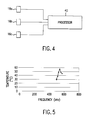
- FIG. 4 is a block diagram of apparatus for analyzing detected cavitation waves to produce images, according to the invention.
- FIG. 5 is a graph showing the relationship between thermal induction caused by cavitation induced by ultrasonic wave and the frequency of the ultrasonic wave.
- the invention provides a screening technique for early detection of ovarian cancers which utilizes an ultrasonic transmitter 12 , and a plurality of receivers 16 a , 16 b , and 16 c .
- the receivers 16 a - 16 c are arranged in a triangulation array in order to obtain three-dimensional location information of possible malignant structures in the ovary.
- the transmitter and receivers are placed on the abdomen of a patient 10 , at a location opposite from ovary 14 .
- the screening technique relies upon the induced formation at characteristic resonant frequencies of cavitation bubbles in the fluid contained in the cystic structures associated with ovarian cancer.
- the induced cavitation forms implosion waves having a spectral content that is relatively easy to measure and to use to identify the location of the cavitation source.
- a resonant response wave can be obtained at a frequency of 529 kHz.
- the use of continuous ultrasonic waves at high energy cause extensive excitation of cavitation and thus increase the temperature to a maximum value at the resonance frequency.
- the location of the peak of temperature rise as shown in FIG. 5 coincides with a resonant induction of cavitation.
- Simultaneous measurement of the wave resulting from implosion of the cavitation bubbles, using a hydrophone transducer showed a significant increase in amplitude at the same frequency.
- ⁇ L is fluid density
- ⁇ shear viscosity
- ⁇ B bulk viscosity
- p pressure
- v particle velocity
- R is the radius of cavitation
- c sound velocity of the fluid
- Pc is pressure in the liquid at the location of the cavitation center in the absence of the cavitation
- P ⁇ is the far field pressure
- Pb is internal pressure of the cavitation.
- the viscosity of the liquid plays an important role in the formation of cavitation.
- the effect of viscosity is to cause damping and loss of mechanical energy during the growth and collapse process. Consequently, it is expected that an increase in viscosity will lead to a decrease in maximum cavity size and rate of growth and collapse.
- the induced impulse level varies although each is activated by the same acoustic source.
- different wave pressure is needed to form a vapor cavity in different liquids.
- Modeling the cavitation phenomenon requires dealing with significant nonlinearity and heterogeneity.
- Nonlinearities arise from changes in temperature, pressure, stress, strain, strain rate, and other properties associated with the input ultrasonic wave. These changes dynamically affect the mechanical and thermal properties of the propagation medium, altering wave speed and attenuation.
- Solving partial differential equations with explicit non-linearity is complicated and time consuming. To avoid these difficulties, linear numerical methods are used.
- incremental linearization can be used. For this type of time-dependent problem, “incrementally linear” means advancing the solution in time by discrete increments and modifying the material properties at the end of each increment. Time increments must be small enough that the solution is linear over each increment.
- a computer simulation can be developed to examine the effect of changing liquid properties and input wave parameters on the induction of cavitation and emission of impulses.
- the frequency of the input wave can be optimized to produce small cavitation for high sensitivity of detection while accounting for the increased attenuation.
- the transabdominal sonography using the transmitter as shown in FIGS. 1A-1B thus can selectively induce cavitation in the cystic fluids of the ovary, which in turn produces singularly detectable and identifiable implosion waves. Ultrasound energy is produced at energy levels and durations that does not result in tissue damage.
- the signals received by the transducers or receivers 16 a - 16 c are used to create a three-dimensional image of ovarian cystic structures. The location of the cyst can be determined using well-established acoustic emission non-destructive testing method technology.
- FIG. 2 shows the relationship between the wavelength, phase and cavitation diameter, at a frequency of approximately 25 kHz. As shown, this results in the inducement of a cavitation bubble of approximately 45 microns in radius. Using a frequency on the order of several hundreds of kilohertz would lead to the induction of cavitation bubbles in the range of several microns.
- the particular resonance frequency for inducing cavitation in cystic fluid conditions representing human ovarian cysts can be identified by subjecting female patients to ultrasonic waves at various frequencies to identify the resonant frequency that uniquely identifies the ovarian cystic fluid. As stated above, in water this condition occurs at 529 kHz.
- FIG. 3 is an illustration showing the general character of cavitation bubbles induced by a focused ultrasonic transducer 12 using a continuous wave.
- the signals from receiver transducers 16 a - 16 c are inputted to a processor 40 , such as a PC, workstation, or other computer, and are processed in conjunction with a triangulation algorithm to obtain a three dimensional image of the cystic structure(s) and its location.
- a processor 40 such as a PC, workstation, or other computer
- a triangulation algorithm to obtain a three dimensional image of the cystic structure(s) and its location.
- FIGS. 1A-1B a number of receiving transducers are placed at preselected locations on the patient's abdomen, proximate the plane of the ovary 14 .
- the received signals are analyzed and processed to determine the three-dimensional distribution of cavitation source sites.
- the control parameters of the ultrasonic waves are determined in advance through experimentation, and are selected to ensure that no damage to tissue or to internal organs results from the application of ultrasonic energy. To ensure that the ultrasonic wave does not produce a significant temperature rise in the patient's tissues, short pulses on the order of milliseconds or shorter are used.
- the control parameters are selected to enable the ultrasonic waves to reach the cavitation excitation threshold level and to selectively induce cavitation in cystic fluid in a manner that maximizes screening sensitivity. Suitable in vivo experimentation can be carried out using artificial cysts of known density in order to identify the values of such control parameters.
- the novel method of the present invention offers a highly sensitive, rapid, non-invasive screening method for patients at high risk for ovarian cancer, and for tracking changes in the size and structures of known abnormalities.
- a follow-up transvaginal sonography test can be made for detailed evaluation when the ultrasonic screening method of the invention indicates the presence of a potential malignancy.
- a similar transmitter-receiver configuration can be implemented for whole breast scanning.
- the method of the present invention also can be used to identify the presence of cystic structures in any human tissue, in addition to ovarian tissue and breast tissue, and therefore may be used in other diagnostic procedures to identify such structures.
Abstract
Description


Claims (14)
Priority Applications (1)
| Application Number | Priority Date | Filing Date | Title |
|---|---|---|---|
| US09/644,096 US6406429B1 (en) | 1999-08-23 | 2000-08-23 | Detection of cystic structures using pulsed ultrasonically induced resonant cavitation |
Applications Claiming Priority (2)
| Application Number | Priority Date | Filing Date | Title |
|---|---|---|---|
| US14990199P | 1999-08-23 | 1999-08-23 | |
| US09/644,096 US6406429B1 (en) | 1999-08-23 | 2000-08-23 | Detection of cystic structures using pulsed ultrasonically induced resonant cavitation |
Publications (1)
| Publication Number | Publication Date |
|---|---|
| US6406429B1 true US6406429B1 (en) | 2002-06-18 |
Family
ID=26847137
Family Applications (1)
| Application Number | Title | Priority Date | Filing Date |
|---|---|---|---|
| US09/644,096 Expired - Lifetime US6406429B1 (en) | 1999-08-23 | 2000-08-23 | Detection of cystic structures using pulsed ultrasonically induced resonant cavitation |
Country Status (1)
| Country | Link |
|---|---|
| US (1) | US6406429B1 (en) |
Cited By (9)
| Publication number | Priority date | Publication date | Assignee | Title |
|---|---|---|---|---|
| US20060184075A1 (en) * | 2001-01-19 | 2006-08-17 | Hmt High Medical Technologies Ag | Method and device for applying pressure waves to the body of an organism |
| US20070239077A1 (en) * | 2006-03-09 | 2007-10-11 | Haim Azhari | Method and system for lipolysis and body contouring |
| US20090048514A1 (en) * | 2006-03-09 | 2009-02-19 | Slender Medical Ltd. | Device for ultrasound monitored tissue treatment |
| US20100274161A1 (en) * | 2007-10-15 | 2010-10-28 | Slender Medical, Ltd. | Implosion techniques for ultrasound |
| US20110178541A1 (en) * | 2008-09-12 | 2011-07-21 | Slender Medical, Ltd. | Virtual ultrasonic scissors |
| US20110174990A1 (en) * | 2009-04-30 | 2011-07-21 | Taleyarkhan Rusi P | Compositions and methods for determining directionality of radiation |
| US20140339426A1 (en) * | 2011-12-14 | 2014-11-20 | Purdue Research Foundation | Direction-position sensing fast neutron detector |
| US8910727B2 (en) | 2006-02-03 | 2014-12-16 | California Institute Of Technology | Ultrasonic/sonic jackhammer |
| WO2018037130A1 (en) * | 2016-08-26 | 2018-03-01 | INSERM (Institut National de la Santé et de la Recherche Médicale) | Method and system for localizing a region of interest in a medium in which cavitation occurs |
Citations (6)
| Publication number | Priority date | Publication date | Assignee | Title |
|---|---|---|---|---|
| US5018508A (en) * | 1988-06-03 | 1991-05-28 | Fry Francis J | System and method using chemicals and ultrasound or ultrasound alone to replace more conventional surgery |
| US5209221A (en) * | 1988-03-01 | 1993-05-11 | Richard Wolf Gmbh | Ultrasonic treatment of pathological tissue |
| US5219401A (en) * | 1989-02-21 | 1993-06-15 | Technomed Int'l | Apparatus for selective destruction of cells by implosion of gas bubbles |
| US5368032A (en) * | 1993-11-09 | 1994-11-29 | General Electric Company | Manually positioned focussed energy system guided by medical imaging |
| US5435311A (en) * | 1989-06-27 | 1995-07-25 | Hitachi, Ltd. | Ultrasound therapeutic system |
| US5558092A (en) * | 1995-06-06 | 1996-09-24 | Imarx Pharmaceutical Corp. | Methods and apparatus for performing diagnostic and therapeutic ultrasound simultaneously |
-
2000
- 2000-08-23 US US09/644,096 patent/US6406429B1/en not_active Expired - Lifetime
Patent Citations (6)
| Publication number | Priority date | Publication date | Assignee | Title |
|---|---|---|---|---|
| US5209221A (en) * | 1988-03-01 | 1993-05-11 | Richard Wolf Gmbh | Ultrasonic treatment of pathological tissue |
| US5018508A (en) * | 1988-06-03 | 1991-05-28 | Fry Francis J | System and method using chemicals and ultrasound or ultrasound alone to replace more conventional surgery |
| US5219401A (en) * | 1989-02-21 | 1993-06-15 | Technomed Int'l | Apparatus for selective destruction of cells by implosion of gas bubbles |
| US5435311A (en) * | 1989-06-27 | 1995-07-25 | Hitachi, Ltd. | Ultrasound therapeutic system |
| US5368032A (en) * | 1993-11-09 | 1994-11-29 | General Electric Company | Manually positioned focussed energy system guided by medical imaging |
| US5558092A (en) * | 1995-06-06 | 1996-09-24 | Imarx Pharmaceutical Corp. | Methods and apparatus for performing diagnostic and therapeutic ultrasound simultaneously |
Cited By (16)
| Publication number | Priority date | Publication date | Assignee | Title |
|---|---|---|---|---|
| US20060184075A1 (en) * | 2001-01-19 | 2006-08-17 | Hmt High Medical Technologies Ag | Method and device for applying pressure waves to the body of an organism |
| US8910727B2 (en) | 2006-02-03 | 2014-12-16 | California Institute Of Technology | Ultrasonic/sonic jackhammer |
| US20070239077A1 (en) * | 2006-03-09 | 2007-10-11 | Haim Azhari | Method and system for lipolysis and body contouring |
| US20090048514A1 (en) * | 2006-03-09 | 2009-02-19 | Slender Medical Ltd. | Device for ultrasound monitored tissue treatment |
| US9107798B2 (en) | 2006-03-09 | 2015-08-18 | Slender Medical Ltd. | Method and system for lipolysis and body contouring |
| US20100274161A1 (en) * | 2007-10-15 | 2010-10-28 | Slender Medical, Ltd. | Implosion techniques for ultrasound |
| US20110178541A1 (en) * | 2008-09-12 | 2011-07-21 | Slender Medical, Ltd. | Virtual ultrasonic scissors |
| AU2010242954B2 (en) * | 2009-04-30 | 2013-11-14 | Rusi P. Taleyarkhan | Compositions and methods for determining directionality of radiation |
| US8436316B2 (en) * | 2009-04-30 | 2013-05-07 | Sagamore/Adams Laboratories Llc | Compositions and methods for determining directionality of radiation |
| JP2012525598A (en) * | 2009-04-30 | 2012-10-22 | ルシ・ピー・タレヤーカーン | Compositions and methods for identifying radiation directionality |
| US20110174990A1 (en) * | 2009-04-30 | 2011-07-21 | Taleyarkhan Rusi P | Compositions and methods for determining directionality of radiation |
| US9201151B2 (en) * | 2009-04-30 | 2015-12-01 | Sagamore/Adams Laboratories Llc | Compositions and methods for determining directionality of radiation |
| US20140339426A1 (en) * | 2011-12-14 | 2014-11-20 | Purdue Research Foundation | Direction-position sensing fast neutron detector |
| US9348039B2 (en) * | 2011-12-14 | 2016-05-24 | Purdue Research Foundation | Direction-position sensing fast neutron detector |
| WO2018037130A1 (en) * | 2016-08-26 | 2018-03-01 | INSERM (Institut National de la Santé et de la Recherche Médicale) | Method and system for localizing a region of interest in a medium in which cavitation occurs |
| US11602327B2 (en) | 2016-08-26 | 2023-03-14 | Inserm (Institut National De La Sante Et De La Recherche Medicale) | Method and system for localizing a region of interest in a medium in which cavitation occurs |
Similar Documents
| Publication | Publication Date | Title |
|---|---|---|
| US5487387A (en) | Method and apparatus for distinguishing between solid masses and fluid-filled cysts | |
| Bassett et al. | Breast sonography. | |
| US8376947B2 (en) | Application of image-based dynamic ultrasound spectrography (IDUS) in detection and localization of breast microcalcifcation | |
| Nakashima et al. | JSUM ultrasound elastography practice guidelines: breast | |
| CN101090670B (en) | Ultrasonic image-guided tissue-damaging system and method | |
| US5997477A (en) | Apparatus for imaging an element within a tissue and method therefor | |
| Barr | Breast elastography: how to perform and integrate into a “Best‐Practice” patient treatment algorithm | |
| US6406429B1 (en) | Detection of cystic structures using pulsed ultrasonically induced resonant cavitation | |
| Khalitov et al. | The use of the Verasonics ultrasound system to measure shear wave velocities in CIRS phantoms | |
| JP2001519674A (en) | Elastography measurement and imaging method and apparatus for implementing the method | |
| Dalir et al. | Detection and identification of subcutaneous defects using ultrasonic waves in reflective test | |
| Wang et al. | Preliminary results of acoustic radiation force impulse imaging by combined qualitative and quantitative analyses for evaluation of breast lesions | |
| Dempsey | Breast sonography: historical perspective, clinical application, and image interpretation | |
| Duric et al. | Detection and characterization of breast masses with ultrasound tomography: clinical results | |
| Rosoff et al. | Ultrasonography in prostate cancer: current roles and potential applications in radiorecurrent disease | |
| Svensson | The value of ultrasound scanning in breast disease | |
| BALDwIN | Breast ultrasound elastography | |
| Jacobo et al. | Basic principles of intraoperative ultrasound applied to brain tumor surgery | |
| Rosenzweig et al. | Advanced ultrasound: prostate elastography and photoacoustic imaging | |
| Alizad | Breast shear wave elastography | |
| Greenleaf et al. | Ultrasound stimulated vibro-acoustography | |
| Liu | Real-time diagnosis of hifu lesion formation by ultrasound elastography | |
| Alotaibi et al. | Ultrasound Elastography Image Artifacts | |
| Basiari et al. | Differential Diagnosis of Cervical Lymph Nodes with Ultrasound and Virtual Touch Imaging Quantification: a Report of Three Cases | |
| Raghu et al. | Breast Ultrasound Overview |
Legal Events
| Date | Code | Title | Description |
|---|---|---|---|
| AS | Assignment |
Owner name: CITY OF HOPE, CALIFORNIA Free format text: ASSIGNMENT OF ASSIGNORS INTEREST;ASSIGNORS:KOVACH, JOHN S.;BAR-COHEN, YOSEPH;REEL/FRAME:011371/0350;SIGNING DATES FROM 20001128 TO 20001201 Owner name: JPL, CALIFORNIA Free format text: ASSIGNMENT OF ASSIGNORS INTEREST;ASSIGNORS:KOVACH, JOHN S.;BAR-COHEN, YOSEPH;REEL/FRAME:011371/0350;SIGNING DATES FROM 20001128 TO 20001201 |
|
| AS | Assignment |
Owner name: CALIFORNIA INSTITUTE OF TECHNOLOGY, CALIFORNIA Free format text: ASSIGNMENT OF ASSIGNORS INTEREST;ASSIGNOR:BAR-COHEN, YOSEPH;REEL/FRAME:011969/0443 Effective date: 20010605 |
|
| AS | Assignment |
Owner name: NATIONAL AERONAUTICS AND SPACE ADMINISTRATION, DIS Free format text: CONFIRMATORY LICENSE;ASSIGNOR:CALIFORNIA INSTITUTE OF TECHNOLOGY;REEL/FRAME:012172/0583 Effective date: 20010724 |
|
| STCF | Information on status: patent grant |
Free format text: PATENTED CASE |
|
| CC | Certificate of correction | ||
| FPAY | Fee payment |
Year of fee payment: 4 |
|
| FPAY | Fee payment |
Year of fee payment: 8 |
|
| FPAY | Fee payment |
Year of fee payment: 12 |