US6409134B1 - Arm apparatus for mounting electronic devices with cable management system - Google Patents
Arm apparatus for mounting electronic devices with cable management system Download PDFInfo
- Publication number
- US6409134B1 US6409134B1 US09/406,006 US40600699A US6409134B1 US 6409134 B1 US6409134 B1 US 6409134B1 US 40600699 A US40600699 A US 40600699A US 6409134 B1 US6409134 B1 US 6409134B1
- Authority
- US
- United States
- Prior art keywords
- extension arm
- endcap
- channel
- hole
- cable
- Prior art date
- Legal status (The legal status is an assumption and is not a legal conclusion. Google has not performed a legal analysis and makes no representation as to the accuracy of the status listed.)
- Expired - Lifetime
Links
Images


Classifications
-
- F—MECHANICAL ENGINEERING; LIGHTING; HEATING; WEAPONS; BLASTING
- F16—ENGINEERING ELEMENTS AND UNITS; GENERAL MEASURES FOR PRODUCING AND MAINTAINING EFFECTIVE FUNCTIONING OF MACHINES OR INSTALLATIONS; THERMAL INSULATION IN GENERAL
- F16M—FRAMES, CASINGS OR BEDS OF ENGINES, MACHINES OR APPARATUS, NOT SPECIFIC TO ENGINES, MACHINES OR APPARATUS PROVIDED FOR ELSEWHERE; STANDS; SUPPORTS
- F16M13/00—Other supports for positioning apparatus or articles; Means for steadying hand-held apparatus or articles
- F16M13/02—Other supports for positioning apparatus or articles; Means for steadying hand-held apparatus or articles for supporting on, or attaching to, an object, e.g. tree, gate, window-frame, cycle
-
- F—MECHANICAL ENGINEERING; LIGHTING; HEATING; WEAPONS; BLASTING
- F16—ENGINEERING ELEMENTS AND UNITS; GENERAL MEASURES FOR PRODUCING AND MAINTAINING EFFECTIVE FUNCTIONING OF MACHINES OR INSTALLATIONS; THERMAL INSULATION IN GENERAL
- F16M—FRAMES, CASINGS OR BEDS OF ENGINES, MACHINES OR APPARATUS, NOT SPECIFIC TO ENGINES, MACHINES OR APPARATUS PROVIDED FOR ELSEWHERE; STANDS; SUPPORTS
- F16M11/00—Stands or trestles as supports for apparatus or articles placed thereon Stands for scientific apparatus such as gravitational force meters
- F16M11/02—Heads
- F16M11/04—Means for attachment of apparatus; Means allowing adjustment of the apparatus relatively to the stand
- F16M11/06—Means for attachment of apparatus; Means allowing adjustment of the apparatus relatively to the stand allowing pivoting
- F16M11/10—Means for attachment of apparatus; Means allowing adjustment of the apparatus relatively to the stand allowing pivoting around a horizontal axis
-
- F—MECHANICAL ENGINEERING; LIGHTING; HEATING; WEAPONS; BLASTING
- F16—ENGINEERING ELEMENTS AND UNITS; GENERAL MEASURES FOR PRODUCING AND MAINTAINING EFFECTIVE FUNCTIONING OF MACHINES OR INSTALLATIONS; THERMAL INSULATION IN GENERAL
- F16M—FRAMES, CASINGS OR BEDS OF ENGINES, MACHINES OR APPARATUS, NOT SPECIFIC TO ENGINES, MACHINES OR APPARATUS PROVIDED FOR ELSEWHERE; STANDS; SUPPORTS
- F16M11/00—Stands or trestles as supports for apparatus or articles placed thereon Stands for scientific apparatus such as gravitational force meters
- F16M11/20—Undercarriages with or without wheels
- F16M11/2007—Undercarriages with or without wheels comprising means allowing pivoting adjustment
- F16M11/2014—Undercarriages with or without wheels comprising means allowing pivoting adjustment around a vertical axis
-
- F—MECHANICAL ENGINEERING; LIGHTING; HEATING; WEAPONS; BLASTING
- F16—ENGINEERING ELEMENTS AND UNITS; GENERAL MEASURES FOR PRODUCING AND MAINTAINING EFFECTIVE FUNCTIONING OF MACHINES OR INSTALLATIONS; THERMAL INSULATION IN GENERAL
- F16M—FRAMES, CASINGS OR BEDS OF ENGINES, MACHINES OR APPARATUS, NOT SPECIFIC TO ENGINES, MACHINES OR APPARATUS PROVIDED FOR ELSEWHERE; STANDS; SUPPORTS
- F16M11/00—Stands or trestles as supports for apparatus or articles placed thereon Stands for scientific apparatus such as gravitational force meters
- F16M11/20—Undercarriages with or without wheels
- F16M11/2092—Undercarriages with or without wheels comprising means allowing depth adjustment, i.e. forward-backward translation of the head relatively to the undercarriage
-
- F—MECHANICAL ENGINEERING; LIGHTING; HEATING; WEAPONS; BLASTING
- F16—ENGINEERING ELEMENTS AND UNITS; GENERAL MEASURES FOR PRODUCING AND MAINTAINING EFFECTIVE FUNCTIONING OF MACHINES OR INSTALLATIONS; THERMAL INSULATION IN GENERAL
- F16M—FRAMES, CASINGS OR BEDS OF ENGINES, MACHINES OR APPARATUS, NOT SPECIFIC TO ENGINES, MACHINES OR APPARATUS PROVIDED FOR ELSEWHERE; STANDS; SUPPORTS
- F16M11/00—Stands or trestles as supports for apparatus or articles placed thereon Stands for scientific apparatus such as gravitational force meters
- F16M11/20—Undercarriages with or without wheels
- F16M11/24—Undercarriages with or without wheels changeable in height or length of legs, also for transport only, e.g. by means of tubes screwed into each other
-
- A—HUMAN NECESSITIES
- A47—FURNITURE; DOMESTIC ARTICLES OR APPLIANCES; COFFEE MILLS; SPICE MILLS; SUCTION CLEANERS IN GENERAL
- A47B—TABLES; DESKS; OFFICE FURNITURE; CABINETS; DRAWERS; GENERAL DETAILS OF FURNITURE
- A47B2200/00—General construction of tables or desks
- A47B2200/0084—Accessories for tables or desks
- A47B2200/0088—Appliance support having rotary joint or articulated connection
-
- F—MECHANICAL ENGINEERING; LIGHTING; HEATING; WEAPONS; BLASTING
- F16—ENGINEERING ELEMENTS AND UNITS; GENERAL MEASURES FOR PRODUCING AND MAINTAINING EFFECTIVE FUNCTIONING OF MACHINES OR INSTALLATIONS; THERMAL INSULATION IN GENERAL
- F16M—FRAMES, CASINGS OR BEDS OF ENGINES, MACHINES OR APPARATUS, NOT SPECIFIC TO ENGINES, MACHINES OR APPARATUS PROVIDED FOR ELSEWHERE; STANDS; SUPPORTS
- F16M2200/00—Details of stands or supports
- F16M2200/04—Balancing means
- F16M2200/044—Balancing means for balancing rotational movement of the undercarriage
-
- F—MECHANICAL ENGINEERING; LIGHTING; HEATING; WEAPONS; BLASTING
- F16—ENGINEERING ELEMENTS AND UNITS; GENERAL MEASURES FOR PRODUCING AND MAINTAINING EFFECTIVE FUNCTIONING OF MACHINES OR INSTALLATIONS; THERMAL INSULATION IN GENERAL
- F16M—FRAMES, CASINGS OR BEDS OF ENGINES, MACHINES OR APPARATUS, NOT SPECIFIC TO ENGINES, MACHINES OR APPARATUS PROVIDED FOR ELSEWHERE; STANDS; SUPPORTS
- F16M2200/00—Details of stands or supports
- F16M2200/06—Arms
- F16M2200/063—Parallelogram arms
-
- F—MECHANICAL ENGINEERING; LIGHTING; HEATING; WEAPONS; BLASTING
- F16—ENGINEERING ELEMENTS AND UNITS; GENERAL MEASURES FOR PRODUCING AND MAINTAINING EFFECTIVE FUNCTIONING OF MACHINES OR INSTALLATIONS; THERMAL INSULATION IN GENERAL
- F16M—FRAMES, CASINGS OR BEDS OF ENGINES, MACHINES OR APPARATUS, NOT SPECIFIC TO ENGINES, MACHINES OR APPARATUS PROVIDED FOR ELSEWHERE; STANDS; SUPPORTS
- F16M2200/00—Details of stands or supports
- F16M2200/06—Arms
- F16M2200/065—Arms with a special structure, e.g. reinforced or adapted for space reduction
-
- Y—GENERAL TAGGING OF NEW TECHNOLOGICAL DEVELOPMENTS; GENERAL TAGGING OF CROSS-SECTIONAL TECHNOLOGIES SPANNING OVER SEVERAL SECTIONS OF THE IPC; TECHNICAL SUBJECTS COVERED BY FORMER USPC CROSS-REFERENCE ART COLLECTIONS [XRACs] AND DIGESTS
- Y10—TECHNICAL SUBJECTS COVERED BY FORMER USPC
- Y10S—TECHNICAL SUBJECTS COVERED BY FORMER USPC CROSS-REFERENCE ART COLLECTIONS [XRACs] AND DIGESTS
- Y10S248/00—Supports
- Y10S248/917—Video display screen support
- Y10S248/919—Adjustably orientable video screen support
-
- Y—GENERAL TAGGING OF NEW TECHNOLOGICAL DEVELOPMENTS; GENERAL TAGGING OF CROSS-SECTIONAL TECHNOLOGIES SPANNING OVER SEVERAL SECTIONS OF THE IPC; TECHNICAL SUBJECTS COVERED BY FORMER USPC CROSS-REFERENCE ART COLLECTIONS [XRACs] AND DIGESTS
- Y10—TECHNICAL SUBJECTS COVERED BY FORMER USPC
- Y10T—TECHNICAL SUBJECTS COVERED BY FORMER US CLASSIFICATION
- Y10T403/00—Joints and connections
- Y10T403/57—Distinct end coupler
- Y10T403/5741—Separate screw or pin-type connections
Definitions
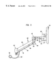
- FIG. 3 illustrates a sideview of the clevis 48 including a tapped hole 50 in the center thereof.
- the tapped hole 50 receives the threaded rod 38 , as shown in FIG. 2 .
- At a first end of the clevis 48 is a pair of fastening members 52 , 54 to which are fastened one end of the gas spring 28 .
- a second end 56 of the clevis 48 is configured to slidably engage a track 58 which is integrally molded in the first endcap 12 (see FIG. 2 ).
- an extension arm suitable to mount a flat-screen electronic peripheral device such as a computer monitor or television, that is inexpensive and easy to manufacture and assemble, that permits a flat-screen device to be mounted substantially flush with the mounting surface, and that enables the cables to and from the flat-screen device to be substantially hidden from view within the extension arm and thus protected from the elements.
- the forearm extension is a U-shaped channel with a first coupling disposed at one end for rotatably coupling to a tilter, a platform or other means for supporting a flat-screen device.
- the forearm extension has a second coupling disposed at the other end for rotatably coupling to the shaft of the second endcap.
- the first endcap also includes a clevis pivotably attached to the second end of the gas spring and a threaded rod threadedly engaging the clevis, such that the clevis slides within the first endcap when the rod rotates around its axial centerline.
- the threaded rod is rotatably secured within the first endcap by a retainer clip and a pair of screws.
- a cable can be substantially hidden from view by being disposed within the extension arm.
- the cable is disposed within the lower channel, the second endcap and the forearm extension.
- the lower channel includes a cable channel formed in a lower surface thereof so that the cable can be inserted within the lower channel.
- the cable is held in place within the lower channel by a cable cover which engages the cable channel.
- the second endcap has a hollow shaft so that the cable can be fed through the shaft to the forearm extension.
- the second coupling of the forearm extension has a hole in an interior wall so that the cable can be disposed through the hole and into the U-shaped channel.
- the cable is held within the U-shaped channel by a cable clip.
- FIG. 2 illustrates a first endcap of an extension arm, in accordance with the prior art
- FIG. 7 illustrates a forearm extension of an extension arm, in accordance with the prior art
- FIG. 8 is an exploded assembly drawing of an extension arm having an interior cable management system for adjustably mounting a flat-screen device to a support mount, according to one embodiment of the invention
- FIGS. 10 a- 10 d illustrate several views of a first endcap, in accordance with one embodiment of the invention.
- FIGS. 17 a- 17 b illustrate several views of a bushing used in a second female coupling of the extension arm illustrated in FIGS. 16 a- 16 b.
- FIGS 10 a and 10 b illustrate the first endcap 102 , in accordance with one embodiment of the invention.
- the first endcap 102 includes a partially-enclosed housing 112 which has flat, oppositely-disposed endwalls 146 and 148 fixedly connected by a sidewall 150 .
- the sidewall 150 extends partially around the partially-enclosed housing 112 so as to permit manipulation of components to be assembled within the first endcap 102 .
- the endwalls 146 and 148 are semi-circular in shape and are connected along a semi-circular edge to the sidewall 150 , which extends perpendicularly therebetween.
- FIG. 10 a illustrates the first endcap 102 having a shaft 114 disposed on the endwall 148 .
- the shaft 114 is preferably integrally molded to the endwall 148 of the first endcap 102 .
- the endwall 146 has a hole 152 disposed therethrough.
- the partially enclosed housing 112 is configured with, for example, holes 116 to receive a connection mechanism, such as pins 118 , therethrough,
- the shaft 114 is configured to be inserted for pivotable rotation in a support mount (not shown), which may be a wall, desk or pole mount, or a configurable mount as shown and described in Applicant's co-pending patent applications: application Ser. No. 60/106,729 filed on Nov. 2, 1998 and application Ser. No. 60/108,469 filed on Nov. 14, 1998.
- FIGS. 11 a-d illustrate several views of the upper channel 104 , according to one embodiment of the invention.
- the upper channel 104 includes a U-shaped body 130 and integrally cast rollers 132 disposed at opposite ends of the U-shaped body 130 .
- the U-shaped body 130 comprises a channel bottom 180 from which extend two channel sidewalls 182 .
- the channel bottom 180 , the sidewalls 182 and the rollers 132 of the upper channel 104 are preferably integrally cast from zinc, which gives the upper channel 104 a lesser weight, and a degree of structural rigidity, more suitable for lighter-weight flat-screen devices than the prior art upper channel 14 which is stamped from heavy gauge steel.
- the rollers 132 have a hole 184 therethrough (either cast or subsequently drilled) for receiving a connection mechanism, such as the pins 118 .
- the upper channel 104 comprises a threaded hole 186 configured and sized to receive a threaded end of a ball stud 138 .
- the threaded hole 186 is also integrally cast.
- the ball stud 138 is configured and sized to receive a second end of the gas spring 122 .
- the upper channel 104 of the invention is cast molded.
- the use of cast molding ensures the angle between the channel bottom 180 and the sidewalls 182 is exactly the same each and every time.
- cast molding enables the sidewalls 182 to be tapered.
- both an outer surface and an inner surface of the sidewalls 182 may taper in, for example, by approximately 1 degree. It should be noted that the taper is not limited to 1 degree, and that the taper of the inner surface and the outer surface need not be the same.
- the taper provides several advantages including more clearance between the upper and the lower channels 104 , 106 when the upper and the lower channels 104 , 106 are brought together during usage. That is, the inner surface of the sidewalls 182 being displaced by 1 degree means that there will be additional clearance for the lower channel 106 to fit therewithin. The additional clearance will help prevent the upper channel 104 and the lower channel 106 from scraping together.
- FIGS. 12 a - 12 e illustrate several views of the lower channel 106 , according to one embodiment of the invention.
- the lower channel 106 includes a U-shaped body 134 having a longitudinal axis 200 and integrally cast rollers 136 disposed at opposite ends of the U-shaped body 134 .
- the U-shaped body 134 of the lower channel 106 comprises a channel bottom 190 from which extend two channel sidewalls 192 .
- the channel bottom 190 , the sidewalls 192 and the rollers 136 of the lower channel 106 are preferably integrally cast from zinc, which gives the lower channel 106 a lesser weight when compared to heavy gauge steel, and a degree of structural rigidity, more suitable for lighter-weight flat-screen devices.
- the rollers 136 have a hole 194 therethrough (either cast or subsequently drilled) for receiving a connection mechanism, such as the pins 118 .
- the channel bottom 190 additionally includes a cable channel 196 running longitudinally therealong.
- a first end 197 of the cable channel 196 starts near an end of the channel bottom 190 that pivotably connects to the first endcap 102 .
- the cable channel 196 then runs along the entire length of the channel bottom 190 to the end of the channel bottom 190 that pivotably connects to the second endcap 108 .
- the second end 199 of the cable channel 196 is an opening between the roller 136 at the end of the channel bottom that pivotably connects to the second endcap 108 .
- the first end 197 may be, for example, rounded to improve the rigidity of the lower channel 106 .
- the cable channel 196 is configured to receive a cable cover 198 (illustrated in FIG.
- cables of the mounted device may be substantially retained within the lower channel 106 so as to hide them from view and protect them from harm.
- the cable channel 196 and the cable cover 198 enable cables to be accessed when desired, while securing them within the lower channel 106 .
- the sidewalls 192 of the lower channel 106 are tapered.
- an outer surface of the sidewalls 192 may be tapered approximately ⁇ fraction (1/2 ) ⁇ degree while an inner surface may be tapered approximately 1 degree.
- the taper is not limited to a particular angle, and that the taper of the inner surface and the outer surface may be the same. The taper is possible because the lower channel 106 is, in the preferred embodiment, cast molded. As noted above with respect to the upper channel 104 , the taper provides more clearance between the upper channel 104 and the lower channel 106 so as to reduce or eliminate the chance of the upper and the lower channels 104 , 106 scraping.
- the cable cover 198 includes a top cover 202 with two sidewalls 204 protruding therefrom. A far end of each sidewall 204 has a catch 206 formed thereon so as to engage with the cable channel 196 .
- the second endcap 108 includes a partially enclosed housing 250 and a shaft assembly 252 as shown in FIG. 8 .
- the partially enclosed housing 250 has a first endwall 254 and a second endwall 256 oppositely-disposed from each other and fixedly connected by a sidewall 258 .
- the sidewall 258 extends partially around the partially-enclosed housing 250 so as to permit manipulation of component, such as cables, which may be contained therewithin.
- the first endwall 254 has a hole 260 disposed therethrough and threaded holes 262 disposed therein that are in communication with the hole 260 . Disposed with the threaded holes 262 are set screws 264 .
- the diameter of the hole 260 is large enough to allow a plug end of a cable to fit therethrough.
- the shaft assembly 252 preferably includes two symmetrical endcap adapters 266 which when assembled provide a hollow shaft 268 .
- the endcap adapter 266 have a mounting end 270 and a shaft end 272 that is thinner than the mounting end 270 .
- the mounting end 270 of both of the endcap adapters 266 are inserted into the hole 260 and are coupled together and to the partially enclosed housing 250 , to form the second endcap 108 , by tightening the set screws 264 .
- the upper and the lower channels 104 , 106 and the first and the second endcaps 102 , 108 are configured so as to form an adjustable parallelogram.
- the shaft 114 of the first endcap 102 and the hollow shaft 268 of the second endcap 108 point in opposite directions.
- the shaft 114 of the first endcap 102 extends vertically downward while the hollow shaft 268 of the second endcap 108 extends vertically upward.
- the shape of the parallelogram is retained by the gas spring 122 .
- the first end of the gas spring 122 is attached to the ball stud 138 mounted within the upper channel 104 and the second end is adjustably mounted to the clevis 120 within the first endcap 102 .
- the gas spring 122 is sized so as to have a fixed length until an upward or downward force is exerted at the second endcap 109 that exceeds the gas spring's designed resistance.
- the gas spring 122 retains the parallelogram shape when the only force exerted at the second endcap 108 is the weight of the flat-screen device.
- the gas spring 122 permits the parallelogram shape to be adjusted when a user pushes the flat-screen device coupled to the forearm extension 110 up or down.
- the forearm extension 110 includes a body 140 having a first female coupling 142 located on a first end and a second female coupling 144 located on a second end.
- the first female coupling 142 has an inner diameter 209 that is sized to rotatably engage the hollow shaft 268 of the second endcap 108 .
- the first female coupling 142 is also configured to receive a cable through the hollow shaft 268 . That is, the first female coupling 142 has a cable slot 274 formed therein, for example by milling the cable slot 274 into the first female coupling 142 , or by casting the first female coupling 142 with the cable slot 274 integrally formed therein.
- the first female coupling 142 preferably has a set screw 212 formed within a wall 214 thereof.
- the set screw 212 can be tightened to prevent the first female coupling 142 from rotating about the hollow shaft 268 .
- the first female coupling 142 has a plurality of voids 217 formed in the wall 214 , which saves on material costs and permits the forearm extension 110 , when cast, to be cooled more quickly. The quicker cooling enables the production quantity to be increased.
- a bushing 210 (FIG. 8) is preferably used to engage the first female coupling 142 and the hollow shaft 268 . That is, the bushing 210 is placed over the hollow shaft 268 and within the first female coupling 142 .
- the bushing 210 is preferably made of a smooth material, such as plastic, in order to reduce friction and prevent metal to metal contact.
- the bushing 210 also has a cable slot 276 formed therein. The cable slots 274 , 276 are aligned so that a cable can pass therethrough.
- the body 140 preferably has an inverted U-shape with a topwall 207 and two sidewalls 208 so that a cable can be hidden therein.
- a cable holder 278 (FIG. 8 ).
- the cable holder 278 secures a cable within the U-shaped body so that it can be hidden from view as it travels the length of the forearm extension 110 .
- the second female coupling 144 is for attachment to a device mounting (not shown), such as a tilter (described in Applicant's co-pending patent application Ser. No. 60/137,088 filed on Jun. 2, 1999), a platform, or other means for supporting a flat-screen device.
- the second female coupling 144 has an inner diameter 218 that is sized to rotatably engage a shaft of the device mount.
- a bushing 220 (FIG. 8 ), preferably made of a smooth material such as plastic, is placed over the shaft and within the second female coupling 144 .
- the second female coupling 144 preferably has a set screw 222 formed within a wall 224 of the second female coupling 144 .
- the second female coupling 144 also has a plurality of voids 226 formed in the wall 224 .
- the embodiment of the forearm extension 110 illustrated in FIGS. 16 a and 16 b has the topwall 207 flush with an upper edge of the female couplings 142 , 144 . Since the first female coupling 142 is larger than the second female coupling, the center of the first female coupling 142 is not aligned with the center of the second female coupling 144 or an axial centerline 228 of the body 140 . It should be noted that an alternative embodiment is to have the center of the female couplings 142 , 144 and the axial centerline 228 of the body 140 all aligned, so that the topwall 207 would not be aligned with an upper edge of the first female coupling 142 .
- the embodiment illustrated in FIG. 16 a has the body 140 horizontally disposed between the female couplings 142 , 144 when the axial centerlines of the female couplings 142 , 144 are vertically disposed. It should be noted however that the body 140 is not limited to be horizontally disposed and may be disposed at an incline in this embodiment.
- the present invention permits a flat-screen device which is mounted to a wall to be flattened against the wall while hiding the extension arm 100 within the shadow of the device. That is, the forearm extension 110 may be folded into a position which is directly above the upper and the lower channels 104 , 106 . As a result, the mounted device is flush to the mounting surface and substantially hides the parallelogram, formed by the first and the second endcaps 102 , 108 and the upper and the lower channels 104 , 106 , as well as the forearm extension 110 from view. Thus, the aesthetic appeal of the extension arm 100 is increased and the space occupied by the extension arm 100 and the device is minimized.
- a flat screen monitor 300 is attached to a tilter 302 which is rotatably coupled to the second female coupling 144 .
- a cable 304 such as a power cable, proceeds from the monitor 300 to the underside off the U-shaped body 140 of the forearm extension 110 .
- the cable 304 is held in place within the U-shaped body 140 by the cable holder 278 .
- the cable 304 proceeds from the body through the cable slots 274 , 276 in the bushing 210 and the first female coupling 142 .
- the cable then proceeds through the hollow shaft 268 of the second endcap 108 .
- the cable exits the second endcap 208 through the open end of the partially enclosed housing 260 .
- the cable proceeds down the length of the lower channel 106 and exits at the first end 197 of the cable channel 196 .
- the cable 304 is inserted into the extension arm 100 as portions of the extension arm 100 are being assembled. That is, the cable 304 is placed under the U-shaped body 140 of the forearm extension 110 and is held in place by the cable holder 278 . The cable is then passed through the cable slots 274 , 276 . The cable 304 including the plug 306 is then fed through the hole 260 in the second endcap 108 . The second endcap 108 is now assembled by inserting the mounting end 270 of each endcap adapter 268 into the hole 260 , thus surrounding the cable 304 . The endcap adapters 268 are held together and within the hole 260 by tightening the set screws 264 . The hollow shaft 268 is then placed within the first female coupling 142 .
- the cable 304 is placed within the lower channel 106 , prior to the lower channel 106 and the second endcap being secured together. This ensures that the cable 304 is above the roller 136 and is contained within the hollow bar formed by the upper channel 104 and the lower channel 106 .
- a bumper 280 may be placed on the second endwall 256 of the second endcap 108 and a plug 282 may be placed over the first female coupling 142 .
- a washer 284 may be placed over the two endcap adapters 268 to help secure them together.
Abstract
Description
Claims (85)
Priority Applications (18)
| Application Number | Priority Date | Filing Date | Title |
|---|---|---|---|
| US09/406,006 US6409134B1 (en) | 1999-06-07 | 1999-09-24 | Arm apparatus for mounting electronic devices with cable management system |
| PCT/US2000/012594 WO2000073027A2 (en) | 1999-05-10 | 2000-05-10 | Arm apparatus for mounting electronic devices |
| AU48298/00A AU764114B2 (en) | 1999-05-10 | 2000-05-10 | Arm apparatus for mounting electronic devices |
| EP00930486A EP1337726A4 (en) | 1999-05-10 | 2000-05-10 | Arm apparatus for mounting electronic devices |
| EP10010722A EP2267352A1 (en) | 1999-05-10 | 2000-05-10 | Forearm extension for use in an extension arm |
| JP2000621123A JP4713744B2 (en) | 1999-05-10 | 2000-05-10 | Electronic device attachment arm device |
| EP20100010721 EP2264351A1 (en) | 1999-05-10 | 2000-05-10 | Forearm extension for use in an extension arm |
| CA002373199A CA2373199C (en) | 1999-05-10 | 2000-05-10 | Arm apparatus for mounting electronic devices |
| EP10010723A EP2264352A1 (en) | 1999-05-10 | 2000-05-10 | Forearm extension for use in an extension arm |
| EP10010720A EP2264350A1 (en) | 1999-05-10 | 2000-05-10 | Forearm extension for use in an extension arm |
| US09/776,355 US6609691B2 (en) | 1999-06-07 | 2001-02-02 | Arm apparatus for mounting electronic devices with cable management system |
| US10/079,804 US6915994B2 (en) | 1999-06-07 | 2002-02-20 | Arm apparatus for mounting electronic devices with cable management system |
| US10/305,566 US6719253B2 (en) | 1999-06-07 | 2002-11-27 | Channel for an arm apparatus for mounting electronic devices with cable management system |
| US10/305,511 US6726167B2 (en) | 1999-06-07 | 2002-11-27 | Arm apparatus for mounting electronic devices with cable management system |
| US10/448,769 US7100880B2 (en) | 1999-06-07 | 2003-05-30 | Arm apparatus for mounting electronic devices with cable management system |
| AU2003259611A AU2003259611B2 (en) | 1999-05-10 | 2003-10-31 | Channel device |
| AU2003259610A AU2003259610B2 (en) | 1999-05-10 | 2003-10-31 | Forearm extension |
| US10/850,640 US7066433B2 (en) | 1999-06-07 | 2004-05-21 | Arm apparatus for mounting electronic devices with cable management system |
Applications Claiming Priority (2)
| Application Number | Priority Date | Filing Date | Title |
|---|---|---|---|
| US13812099P | 1999-06-07 | 1999-06-07 | |
| US09/406,006 US6409134B1 (en) | 1999-06-07 | 1999-09-24 | Arm apparatus for mounting electronic devices with cable management system |
Related Child Applications (2)
| Application Number | Title | Priority Date | Filing Date |
|---|---|---|---|
| US09/776,355 Continuation-In-Part US6609691B2 (en) | 1999-06-07 | 2001-02-02 | Arm apparatus for mounting electronic devices with cable management system |
| US10/079,804 Division US6915994B2 (en) | 1999-06-07 | 2002-02-20 | Arm apparatus for mounting electronic devices with cable management system |
Publications (1)
| Publication Number | Publication Date |
|---|---|
| US6409134B1 true US6409134B1 (en) | 2002-06-25 |
Family
ID=43598275
Family Applications (4)
| Application Number | Title | Priority Date | Filing Date |
|---|---|---|---|
| US09/406,006 Expired - Lifetime US6409134B1 (en) | 1999-05-10 | 1999-09-24 | Arm apparatus for mounting electronic devices with cable management system |
| US10/079,804 Expired - Lifetime US6915994B2 (en) | 1999-06-07 | 2002-02-20 | Arm apparatus for mounting electronic devices with cable management system |
| US10/305,566 Expired - Lifetime US6719253B2 (en) | 1999-06-07 | 2002-11-27 | Channel for an arm apparatus for mounting electronic devices with cable management system |
| US10/305,511 Expired - Lifetime US6726167B2 (en) | 1999-06-07 | 2002-11-27 | Arm apparatus for mounting electronic devices with cable management system |
Family Applications After (3)
| Application Number | Title | Priority Date | Filing Date |
|---|---|---|---|
| US10/079,804 Expired - Lifetime US6915994B2 (en) | 1999-06-07 | 2002-02-20 | Arm apparatus for mounting electronic devices with cable management system |
| US10/305,566 Expired - Lifetime US6719253B2 (en) | 1999-06-07 | 2002-11-27 | Channel for an arm apparatus for mounting electronic devices with cable management system |
| US10/305,511 Expired - Lifetime US6726167B2 (en) | 1999-06-07 | 2002-11-27 | Arm apparatus for mounting electronic devices with cable management system |
Country Status (1)
| Country | Link |
|---|---|
| US (4) | US6409134B1 (en) |
Cited By (93)
| Publication number | Priority date | Publication date | Assignee | Title |
|---|---|---|---|---|
| WO2003009269A2 (en) * | 2001-07-18 | 2003-01-30 | Daniel Dunn | Multiple flat panel display system |
| US6550734B1 (en) * | 2001-10-15 | 2003-04-22 | Lbp Communications, Inc. | Cantilevered support for wired device |
| WO2003066998A1 (en) * | 2002-02-01 | 2003-08-14 | Innovative Office Products, Inc. | Modular mounting arm |
| AU765351B2 (en) * | 2001-02-02 | 2003-09-18 | Innovative Office Products, Inc. | Arm apparatus for mounting electronic devices with cable management system |
| US20030184712A1 (en) * | 2002-03-26 | 2003-10-02 | Takanori Takeda | Ophthalmologic apparatus |
| WO2003092341A2 (en) | 2002-04-24 | 2003-11-06 | Innovative Office Products, Inc. | Multiple electronic device reorienting support |
| US20030223188A1 (en) * | 2002-05-28 | 2003-12-04 | Samsung Electronics Co., Ltd. | Tilting apparatus of monitor |
| US20040004165A1 (en) * | 2002-07-06 | 2004-01-08 | Samsung Electronics Co., Ltd. | Display apparatus |
| US20040014349A1 (en) * | 2002-04-24 | 2004-01-22 | Innovative Office Products, Inc. | Quick interconnection system for electronic devices |
| US20040012917A1 (en) * | 2002-07-16 | 2004-01-22 | Samsung Electronics Co., Ltd. | Monitor improved in a tilting structure |
| US20040031893A1 (en) * | 2002-08-15 | 2004-02-19 | Smed Ole Falk | Flat panel display system |
| US20040035987A1 (en) * | 2002-05-01 | 2004-02-26 | Innovative Office Products, Inc. | Stackable multiple support arm for electronic devices |
| US20040084578A1 (en) * | 2002-11-05 | 2004-05-06 | Samsung Electronics, Co., Ltd. | Display apparatus |
| US20040084579A1 (en) * | 2002-10-30 | 2004-05-06 | Samsung Electronics Co., Ltd. | Stand for display |
| US6739096B2 (en) | 2001-06-22 | 2004-05-25 | Steelcase Development Corporation | Movable office support system |
| US20040118984A1 (en) * | 2002-09-27 | 2004-06-24 | Samsung Electronics Co., Ltd. | Display apparatus |
| US20040147178A1 (en) * | 2002-11-11 | 2004-07-29 | Samsung Electronics Co., Ltd. | Monitor |
| US20040159757A1 (en) * | 2003-01-09 | 2004-08-19 | Decade Industries, Inc. D/B/A Sanus Systems | Articulated mount |
| US20040211866A1 (en) * | 2001-11-19 | 2004-10-28 | Samsung Electronics Co., Ltd. | Monitor improved in a tilting and combining structure |
| US20040231213A1 (en) * | 2003-05-23 | 2004-11-25 | Samsung Electronic Co., Ltd. | Display apparatus |
| US20050002159A1 (en) * | 2002-09-28 | 2005-01-06 | Samsung Electronics Co., Ltd. | Monitor |
| US20050023422A1 (en) * | 1999-05-10 | 2005-02-03 | Oddsen Odd N. | Arm apparatus for mounting electronic devices |
| US6892650B2 (en) * | 2001-06-22 | 2005-05-17 | Steelcase Development Corporation | Movable display support system |
| US20050133678A1 (en) * | 2002-06-11 | 2005-06-23 | Chief Manufacturing Inc. | Adjustable, self-balancing flat panel display mounting system |
| US20050230585A1 (en) * | 2004-04-19 | 2005-10-20 | Chin-Jui Hung | Support apparatus for suspending a display |
| US20060006297A1 (en) * | 2004-07-07 | 2006-01-12 | Innovative Office Products, Inc. | Arm apparatus with reinforcement |
| US20060022102A1 (en) * | 2003-05-30 | 2006-02-02 | Jay Dittmer | Self-balancing adjustable mounting system with friction adjustment |
| US7028961B1 (en) * | 2003-05-30 | 2006-04-18 | Csav, Inc. | Self-balancing adjustable flat panel mounting system |
| US20060181637A1 (en) * | 2005-02-16 | 2006-08-17 | Innovative Office Products, Inc. | Quick release assembly for an electronic device |
| US20060266903A1 (en) * | 2005-05-31 | 2006-11-30 | Innovative Office Products, Inc. | Tapered mini arm having an anti-loosening mechanism |
| US20060266909A1 (en) * | 2005-05-31 | 2006-11-30 | Innovative Office Products, Inc. | Angled mini arm having a clevis assembly |
| WO2006130324A2 (en) | 2005-05-31 | 2006-12-07 | Innovative Office Products, Inc. | Angled mini arm having a clevis assembly |
| US20070025555A1 (en) * | 2005-07-28 | 2007-02-01 | Fujitsu Limited | Method and apparatus for processing information, and computer product |
| US7182301B1 (en) | 2003-07-21 | 2007-02-27 | Innovative Office Products, Inc. | Mounting bracket for electronic device having dimensional inserts |
| US7189924B1 (en) | 2005-07-01 | 2007-03-13 | Sun Microsystems, Inc. | Rack-mount computer cable management arm |
| US20070084978A1 (en) * | 2005-10-17 | 2007-04-19 | Martin Randall W | Multiple-display mount |
| US20070086153A1 (en) * | 2005-10-17 | 2007-04-19 | Martin Randall W | Display base cable management system and method |
| US20070084624A1 (en) * | 2005-10-17 | 2007-04-19 | Martin Randall W | System and method for managing cables in a display base |
| US20070084625A1 (en) * | 2005-10-17 | 2007-04-19 | Martin Randall W | System and method for managing cables in a display stand |
| US20070138360A1 (en) * | 2005-10-17 | 2007-06-21 | Martin Randall W | System for mounting devices to a display |
| US20070153459A1 (en) * | 2006-01-04 | 2007-07-05 | Jim Wohlford | Mounting system for flat panel electronic display |
| US20070170321A1 (en) * | 2006-01-24 | 2007-07-26 | Smed Ole F | Flat panel monitor mount with low profile ball and socket swivel and tilter mount |
| US20070194196A1 (en) * | 2003-01-09 | 2007-08-23 | Csav, Inc. | Adjustable tilt mount |
| US20070295870A1 (en) * | 2006-06-12 | 2007-12-27 | Peterson Erik R | Wall mounted workstation |
| US20080001866A1 (en) * | 2006-06-28 | 2008-01-03 | Martin Michael M | Control Display Positioning System |
| US20080029663A1 (en) * | 2006-08-04 | 2008-02-07 | Innovative Office Products, Inc. | Laptop holder for extension arm |
| US20080048091A1 (en) * | 2006-07-18 | 2008-02-28 | Aloka Co., Ltd. | Ultrasound diagnosis apparatus |
| US20080067317A1 (en) * | 2006-09-15 | 2008-03-20 | Innovative Office Products, Inc. | Extension arm with moving clevis and cable management |
| US7389963B2 (en) | 2002-08-24 | 2008-06-24 | Samsung Electronics Co., Ltd. | Display apparatus |
| US7410226B1 (en) | 2006-05-18 | 2008-08-12 | Nexus 21, Inc. | Extensible monitor support system |
| US20080236858A1 (en) * | 2007-03-27 | 2008-10-02 | David Quijano | Cable management system |
| US7459634B2 (en) | 2005-10-17 | 2008-12-02 | Hewlett-Packard Development Company, L.P. | System and method for managing cables |
| US20090002190A1 (en) * | 2007-06-27 | 2009-01-01 | Audiovox Corporation | Multi-media memo board |
| US20090039224A1 (en) * | 2007-08-10 | 2009-02-12 | Innovative Office Products, Inc. | Extension arm devices and methods of manufacture |
| US20090050763A1 (en) * | 2007-01-05 | 2009-02-26 | Jay Dittmer | In-wall mount |
| WO2009012379A3 (en) * | 2007-07-17 | 2009-03-05 | Csav Inc | Mount and electronic display system |
| US20090146033A1 (en) * | 2007-12-10 | 2009-06-11 | Sin Yi Chiang | Screen supporting rack |
| US7555581B2 (en) | 2005-10-17 | 2009-06-30 | Hewlett-Packard Development Company, L.P. | Communications display base system and method |
| US20090173869A1 (en) * | 2008-01-07 | 2009-07-09 | Yi-Chung Su | Cantilever structure of mounting frame |
| US7677182B2 (en) | 2004-05-27 | 2010-03-16 | Steelcase Development Corporation | Two person work environment |
| US20100127144A1 (en) * | 2008-11-19 | 2010-05-27 | Lange Tim G | Vertical Motion Pendant Arm |
| US20100142137A1 (en) * | 2008-12-10 | 2010-06-10 | Kenneth Kwak | Display screen mounting device and method |
| US20100149736A1 (en) * | 2007-01-05 | 2010-06-17 | Jay Dittmer | Wall-avoiding self-balancing mount for tilt positioning of a flat panel electronic display |
| US20100148647A1 (en) * | 2008-12-11 | 2010-06-17 | Rubbermaid Incorporated | Wall work station |
| USD620943S1 (en) | 2009-01-07 | 2010-08-03 | Milestone Av Technologies Llc | Single arm display mount |
| USD627787S1 (en) | 2009-01-07 | 2010-11-23 | Milestone Av Technologies Llc | Display mount with single articulating arm |
| US20110226918A1 (en) * | 2002-06-24 | 2011-09-22 | Hirschhorn Bruce D | Dual-Pivoting Adjustable Support Arm |
| US20110233350A1 (en) * | 2010-01-29 | 2011-09-29 | Rubbermaid Incorporated | Work station with height adjustment lock |
| US8072739B2 (en) | 2007-01-03 | 2011-12-06 | Milestone Av Technologies Llc | Device mount with selectively positionable tilt axis |
| US20120006767A1 (en) * | 2010-07-08 | 2012-01-12 | Southco, Inc. | Display Support Apparatus |
| US20120235000A1 (en) * | 2011-03-18 | 2012-09-20 | Borloz Paul Rene | Variable height arm structures, systems, and methods |
| US20130119219A1 (en) * | 2011-11-10 | 2013-05-16 | Bytec Group Limited | Articulated Mechanical Arm |
| US8469323B1 (en) * | 2008-04-21 | 2013-06-25 | Yani Deros | Modular monitor support assembly |
| US8662605B2 (en) | 2011-02-18 | 2014-03-04 | Rubbermaid Incorporated | Mobile technology cabinet |
| US8677911B2 (en) | 2011-02-18 | 2014-03-25 | Rubbermaid Incorporated | Technology cart |
| US8794579B2 (en) | 2005-06-03 | 2014-08-05 | Steelcase, Inc. | Support arm assembly |
| US8891249B2 (en) | 2009-01-07 | 2014-11-18 | Milestone Av Technologies Llc | Display mount with adjustable position tilt axis |
| US20140361584A1 (en) * | 2013-06-07 | 2014-12-11 | Neutral Posture, Inc. | Seating Assembly Having A Seat-Mounted Attachment Assembly For Adjustable Extension Arm |
| US20150007810A1 (en) * | 2013-07-03 | 2015-01-08 | Mathew S. Smith | Delivery of Nebulized Medicines |
| US8960632B2 (en) | 2011-07-05 | 2015-02-24 | Mediamounts, Ltd. | Dual bar linkage monitor support with adustment feature |
| US20150060611A1 (en) * | 2013-08-28 | 2015-03-05 | Kawamura Electric, Inc. | Charging cable support arm |
| US9109742B2 (en) | 2008-09-02 | 2015-08-18 | Milestone Av Technologies Llc | Low profile mount for flat panel electronic display |
| US20170051866A1 (en) * | 2015-08-21 | 2017-02-23 | Syncmold Enterprise Corp. | Supporting stand for display device |
| US9599275B1 (en) * | 2013-03-15 | 2017-03-21 | Pelco Products, Inc. | Security light or other traffic control device with articulating bracket |
| US20170339800A1 (en) * | 2016-05-23 | 2017-11-23 | Vantage Point Products Corp. | Stand |
| US9933106B2 (en) | 2013-03-14 | 2018-04-03 | Capsa Solutions, Llc | Height adjustable support |
| US20180143481A1 (en) * | 2016-09-01 | 2018-05-24 | Samsung Electronics Co., Ltd. | Display apparatus |
| US10357200B2 (en) * | 2006-06-29 | 2019-07-23 | Accuvein, Inc. | Scanning laser vein contrast enhancer having releasable handle and scan head |
| US20190278330A1 (en) * | 2018-03-06 | 2019-09-12 | GCX Corporation | Tablet Support Arm Structures, Systems and Associated Methods |
| US10610010B2 (en) * | 2017-09-18 | 2020-04-07 | Fellowes, Inc. | Multi-positional articulating platform system |
| US11131423B2 (en) | 2016-03-07 | 2021-09-28 | Southco, Inc. | Display support arm assembly for mounting a display |
| US20220290802A1 (en) * | 2021-03-10 | 2022-09-15 | Ningbo Tuotuo River Design Company | Monitor arm with decorative lighting |
| US11530774B2 (en) | 2019-03-01 | 2022-12-20 | GCX Corporation | Joint rotation stop structures for articulated support arms |
Families Citing this family (25)
| Publication number | Priority date | Publication date | Assignee | Title |
|---|---|---|---|---|
| US7407144B2 (en) * | 2001-08-02 | 2008-08-05 | Pedestal Designs Inc. | Pedestals |
| US8127696B2 (en) | 2006-04-04 | 2012-03-06 | Pedestal Designs Inc. | Block pedestal having slidably supported horizontal members |
| US8943983B2 (en) | 2001-08-02 | 2015-02-03 | Pedestal Designs, Inc. | Block pedestal having slidably supported horizontal members |
| US7410138B2 (en) * | 2003-03-14 | 2008-08-12 | Tgr Intellectual Properties, Llc | Display adjustably positionable about swivel and pivot axes |
| DE602005023792D1 (en) * | 2004-06-10 | 2010-11-04 | Humanscale Corp | Mechanism for adjusting the position of a fastened device |
| US7487944B2 (en) * | 2004-06-11 | 2009-02-10 | Custom Plastics, Inc. | Flat screen monitor desktop support |
| GB2416062B (en) * | 2004-07-02 | 2008-02-13 | Ray Hung | Pivot arm suspension unit for a display device |
| EP1703195A1 (en) * | 2005-03-18 | 2006-09-20 | Market Link USA, Inc. | Video monitor mount |
| WO2007114933A2 (en) * | 2006-04-04 | 2007-10-11 | Pedestal Designs Inc. | Rotatable pedestal |
| US9770104B1 (en) | 2006-04-04 | 2017-09-26 | Pedestal Designs, Inc. | Block pedestal having slidably supported horizontal members |
| US7673843B2 (en) * | 2006-04-04 | 2010-03-09 | Petra Reed | Rotatable pedestal |
| DE602006013833D1 (en) * | 2006-10-18 | 2010-06-02 | Jaotech Uk Ltd | Mechanical arm |
| US7891613B2 (en) * | 2006-11-30 | 2011-02-22 | Trade Management Group Limited | Lower arm for FPM support having indented cable tray support |
| US20090101780A1 (en) * | 2007-10-18 | 2009-04-23 | Rbw Industries, Inc. | Flat screen tv bracket for a vehicle |
| US7748670B1 (en) | 2008-02-11 | 2010-07-06 | Veldez Steven C | Television rotational support apparatus |
| US20110149510A1 (en) * | 2009-12-23 | 2011-06-23 | Humanscale Corporation | Adjustable Laptop Holder |
| US20110147546A1 (en) * | 2009-12-23 | 2011-06-23 | Humanscale Corporation | Adjustable Display Arm |
| US9700158B1 (en) | 2012-08-24 | 2017-07-11 | Pedestal Designs, Inc. | Rotatable pedestal components and assemblies |
| US9119486B2 (en) | 2012-08-24 | 2015-09-01 | Pedestal Designs, Inc. | Pedestals |
| US9657889B1 (en) | 2013-03-15 | 2017-05-23 | Humanscale Corporation | Adjustable support arm |
| NL2015811B1 (en) | 2015-11-19 | 2017-06-06 | Vlaar Innovations B V | Monitor arm stand including a coupling piece, and coupling piece for such monitor arm stand. |
| TWM523265U (en) * | 2016-01-04 | 2016-06-01 | Chen Source Inc | Monitor support rack |
| TWM521854U (en) * | 2016-02-03 | 2016-05-11 | Modernsolid Ind Co Ltd | Cantilever adjustment device |
| CN107152597A (en) * | 2016-08-11 | 2017-09-12 | 李宇 | A kind of novel telescopic spring bracing |
| CN113551133B (en) * | 2020-04-24 | 2023-04-07 | 杭州海康威视数字技术股份有限公司 | A hide line support for camera device |
Citations (25)
| Publication number | Priority date | Publication date | Assignee | Title |
|---|---|---|---|---|
| US999283A (en) * | 1911-05-06 | 1911-08-01 | Otis C White | Adjustable bracket. |
| US3131900A (en) | 1962-05-15 | 1964-05-05 | Robert J Anderson | Self leveling paint can holder attachment for ladders |
| US3424419A (en) | 1967-08-03 | 1969-01-28 | Sheldon K Siegel | Block holder |
| US3489383A (en) | 1968-03-15 | 1970-01-13 | William E Anson | Swivel support for a mannequin head |
| US4266747A (en) * | 1979-07-26 | 1981-05-12 | Positioning Devices, Incorporated | Equipoised articulated support arm |
| US4494177A (en) * | 1983-04-20 | 1985-01-15 | Plan Hold Corp. | Articulated task lamp |
| US4687167A (en) * | 1985-10-23 | 1987-08-18 | Skalka Gerald P | Multi-position computer support |
| US4695024A (en) * | 1986-05-09 | 1987-09-22 | Attain, Inc. | Test system manipulator arm |
| US4708312A (en) * | 1985-10-23 | 1987-11-24 | Ncr Corporation | Extensible height-adjustable swivel arm for supporting a display or the like |
| US4768744A (en) * | 1986-08-27 | 1988-09-06 | Richard Leeds | Apparatus for supporting a load in a dynamically balanced condition |
| US4770384A (en) * | 1986-07-28 | 1988-09-13 | Matsushita Electric Works, Ltd. | Movable stand |
| US4821159A (en) | 1988-01-29 | 1989-04-11 | Pike Machine Products Co. | Overlapped lamp swivel for after assembly finishing |
| US4852500A (en) * | 1987-03-18 | 1989-08-01 | Herman Miller, Inc. | Integrated computer implement work area |
| US4852842A (en) | 1987-09-24 | 1989-08-01 | Lucasey Manufacturing Company, Inc. | Appliance support apparatus |
| US5123621A (en) * | 1990-03-07 | 1992-06-23 | First National Investments Limited | Swivel arm for a supporting plate, in particular a monitor supporting plate |
| US5174531A (en) | 1991-07-26 | 1992-12-29 | Farideh Perakis | Hair dryer holder apparatus |
| US5390685A (en) | 1993-03-26 | 1995-02-21 | Mccoy; Jens | Collapsible shelter |
| US5437427A (en) | 1994-01-25 | 1995-08-01 | Johnson; Peter D. | Binocular mounting assembly for astronomical observations |
| US5584596A (en) | 1994-06-10 | 1996-12-17 | Knoll, Inc. | Caliper control for universal support arm |
| US5642819A (en) | 1996-03-13 | 1997-07-01 | Ronia; Ernesto | Christmas stocking holder |
| US5664750A (en) | 1995-11-14 | 1997-09-09 | Cohen; Edward | Camera Mount |
| US5743503A (en) | 1996-03-08 | 1998-04-28 | Ergotron, Inc. | Computer suspension system |
| US6012693A (en) * | 1998-02-19 | 2000-01-11 | Ergotron, Inc. | Multi-function display mounting system |
| US6076785A (en) | 1996-02-29 | 2000-06-20 | Innovative Office Products, Inc. | Ergonomic sit/stand keyboard support mechanism |
| US6179263B1 (en) | 1997-10-14 | 2001-01-30 | Rosen Products Llc | Stowable support apparatus |
Family Cites Families (42)
| Publication number | Priority date | Publication date | Assignee | Title |
|---|---|---|---|---|
| US1551332A (en) * | 1925-08-25 | A cprpora | ||
| US376617A (en) * | 1888-01-17 | Samuel b | ||
| US2151877A (en) * | 1935-11-20 | 1939-03-28 | Clinton L Walker | Display apparatus |
| US3072374A (en) * | 1960-09-19 | 1963-01-08 | Sunbeam Lighting Company | Movable arm for examination light |
| US3348799A (en) * | 1965-11-01 | 1967-10-24 | American Hospital Supply Corp | Tray assembly |
| US3322886A (en) * | 1966-02-09 | 1967-05-30 | Warshawsky Jerome | Swivel joint coupling for lamp arms |
| US3409261A (en) * | 1966-11-07 | 1968-11-05 | Visual Systems Inc | Counterpoising or equipoising mechanism |
| US3436046A (en) * | 1967-09-01 | 1969-04-01 | Ritter Pfaudler Corp | Infinite positioning mechanism for a movable arm |
| US4159093A (en) * | 1978-05-26 | 1979-06-26 | American Optical Corporation | Adjustable support for a headrest |
| DE3014478C2 (en) * | 1980-04-15 | 1982-01-14 | Siemens AG, 1000 Berlin und 8000 München | Arrangement for attaching a monitor to a text station |
| EP0048404B1 (en) * | 1980-09-18 | 1986-02-05 | Firma Carl Zeiss | Adjustable stand for optical observing units |
| US4447031A (en) * | 1981-04-13 | 1984-05-08 | Positioning Devices, Inc. | Spring counterbalanced support arm system |
| US4616798A (en) * | 1982-06-07 | 1986-10-14 | Haworth, Inc. | Adjustable support for CRT keyboard |
| US4459650A (en) * | 1983-01-06 | 1984-07-10 | Pipe Machine Products Company | Wall mounted lamp swivel arm assembly |
| US4826123A (en) * | 1983-05-16 | 1989-05-02 | Knoll International, Inc. | Adjustable keyboard support |
| US4564179A (en) * | 1984-04-12 | 1986-01-14 | Hollingsworth Ashley J | Articulated support arm apparatus |
| US4610630A (en) * | 1985-07-17 | 1986-09-09 | Progressive Machine Products, Inc. | Dental instrument stand |
| US4744019A (en) * | 1986-09-12 | 1988-05-10 | Jac Jacobsen A/S | Counterbalanced arm assembly |
| US4706919A (en) * | 1986-12-17 | 1987-11-17 | Haworth, Inc. | Keyboard support with automatic lowering mechanism |
| US4844387A (en) * | 1986-12-31 | 1989-07-04 | Hunt Holdings, Inc. | Monitor arm apparatus |
| US4783036A (en) * | 1987-04-16 | 1988-11-08 | Anthro Corporation | Adjustable support |
| US4887929A (en) * | 1988-04-25 | 1989-12-19 | Electric Eel Manufacturing Co., Inc. | Cable coupler |
| US5258898A (en) * | 1991-12-19 | 1993-11-02 | Hubbell Incorporated | Electric lighting support assembly |
| US5357414A (en) * | 1993-01-22 | 1994-10-18 | Phoenix Products Company, Inc. | Modular cantilevered electrical light fixture |
| US5348260A (en) * | 1993-02-08 | 1994-09-20 | Hughes Aircraft Company | Movable supporting arm |
| US5379205A (en) * | 1993-10-08 | 1995-01-03 | Peng; Chih-Wen | Structure for a swingable arm mounting base |
| US5387255A (en) * | 1994-01-26 | 1995-02-07 | Chiang; Douglas | Steering bearing assembly for a bicycle |
| US5429336A (en) * | 1994-03-30 | 1995-07-04 | Ko; Hsiwng C. | Wall rack having a turnable support frame and a plastic bushing in a pivot seat thereof |
| US5876008A (en) * | 1995-01-17 | 1999-03-02 | Ergotron, Inc. | Suspension system for video monitor or other equipment |
| US5826846A (en) * | 1996-06-28 | 1998-10-27 | Hill-Rom, Inc. | Monitor arm with constant counterbalance |
| US5697588A (en) * | 1996-07-29 | 1997-12-16 | Ncr Corporation | Adjustable display mount |
| NL1004116C2 (en) * | 1996-09-26 | 1998-03-27 | Vogel S Holding Bv | Devices for supporting an electrical appliance. |
| US5848556A (en) * | 1997-02-26 | 1998-12-15 | Samsung Electronics Co., Ltd. | Robot having dust minimizing cable arrangement |
| JP3701427B2 (en) | 1997-03-11 | 2005-09-28 | 株式会社内田洋行 | Flat display mounting device |
| US5924664A (en) * | 1997-03-12 | 1999-07-20 | Ergo View Technologies Corp. | Keyboard support mechanism |
| JPH1185315A (en) | 1997-09-03 | 1999-03-30 | Uchida Yoko Co Ltd | Display support device |
| US6095468A (en) * | 1998-03-27 | 2000-08-01 | Hill-Rom, Inc. | Support arm for a service column |
| US6257538B1 (en) * | 1998-11-13 | 2001-07-10 | Weber Knapp Company | Keyboard mounting mechanism |
| AU2861200A (en) * | 1999-01-27 | 2000-08-18 | Speck Product Design | Swiveling computer peripheral support assembly |
| US6478274B1 (en) * | 1999-05-10 | 2002-11-12 | Innovative Office Products, Inc. | Arm apparatus for mounting electronic devices |
| US6505988B1 (en) * | 1999-06-02 | 2003-01-14 | Innovative Office Products, Inc. | Tilter for positioning electronic devices |
| US6736364B2 (en) * | 2002-02-01 | 2004-05-18 | Innovative Office Products, Inc. | Modular mounting arm |
-
1999
- 1999-09-24 US US09/406,006 patent/US6409134B1/en not_active Expired - Lifetime
-
2002
- 2002-02-20 US US10/079,804 patent/US6915994B2/en not_active Expired - Lifetime
- 2002-11-27 US US10/305,566 patent/US6719253B2/en not_active Expired - Lifetime
- 2002-11-27 US US10/305,511 patent/US6726167B2/en not_active Expired - Lifetime
Patent Citations (25)
| Publication number | Priority date | Publication date | Assignee | Title |
|---|---|---|---|---|
| US999283A (en) * | 1911-05-06 | 1911-08-01 | Otis C White | Adjustable bracket. |
| US3131900A (en) | 1962-05-15 | 1964-05-05 | Robert J Anderson | Self leveling paint can holder attachment for ladders |
| US3424419A (en) | 1967-08-03 | 1969-01-28 | Sheldon K Siegel | Block holder |
| US3489383A (en) | 1968-03-15 | 1970-01-13 | William E Anson | Swivel support for a mannequin head |
| US4266747A (en) * | 1979-07-26 | 1981-05-12 | Positioning Devices, Incorporated | Equipoised articulated support arm |
| US4494177A (en) * | 1983-04-20 | 1985-01-15 | Plan Hold Corp. | Articulated task lamp |
| US4687167A (en) * | 1985-10-23 | 1987-08-18 | Skalka Gerald P | Multi-position computer support |
| US4708312A (en) * | 1985-10-23 | 1987-11-24 | Ncr Corporation | Extensible height-adjustable swivel arm for supporting a display or the like |
| US4695024A (en) * | 1986-05-09 | 1987-09-22 | Attain, Inc. | Test system manipulator arm |
| US4770384A (en) * | 1986-07-28 | 1988-09-13 | Matsushita Electric Works, Ltd. | Movable stand |
| US4768744A (en) * | 1986-08-27 | 1988-09-06 | Richard Leeds | Apparatus for supporting a load in a dynamically balanced condition |
| US4852500A (en) * | 1987-03-18 | 1989-08-01 | Herman Miller, Inc. | Integrated computer implement work area |
| US4852842A (en) | 1987-09-24 | 1989-08-01 | Lucasey Manufacturing Company, Inc. | Appliance support apparatus |
| US4821159A (en) | 1988-01-29 | 1989-04-11 | Pike Machine Products Co. | Overlapped lamp swivel for after assembly finishing |
| US5123621A (en) * | 1990-03-07 | 1992-06-23 | First National Investments Limited | Swivel arm for a supporting plate, in particular a monitor supporting plate |
| US5174531A (en) | 1991-07-26 | 1992-12-29 | Farideh Perakis | Hair dryer holder apparatus |
| US5390685A (en) | 1993-03-26 | 1995-02-21 | Mccoy; Jens | Collapsible shelter |
| US5437427A (en) | 1994-01-25 | 1995-08-01 | Johnson; Peter D. | Binocular mounting assembly for astronomical observations |
| US5584596A (en) | 1994-06-10 | 1996-12-17 | Knoll, Inc. | Caliper control for universal support arm |
| US5664750A (en) | 1995-11-14 | 1997-09-09 | Cohen; Edward | Camera Mount |
| US6076785A (en) | 1996-02-29 | 2000-06-20 | Innovative Office Products, Inc. | Ergonomic sit/stand keyboard support mechanism |
| US5743503A (en) | 1996-03-08 | 1998-04-28 | Ergotron, Inc. | Computer suspension system |
| US5642819A (en) | 1996-03-13 | 1997-07-01 | Ronia; Ernesto | Christmas stocking holder |
| US6179263B1 (en) | 1997-10-14 | 2001-01-30 | Rosen Products Llc | Stowable support apparatus |
| US6012693A (en) * | 1998-02-19 | 2000-01-11 | Ergotron, Inc. | Multi-function display mounting system |
Cited By (202)
| Publication number | Priority date | Publication date | Assignee | Title |
|---|---|---|---|---|
| US20050023422A1 (en) * | 1999-05-10 | 2005-02-03 | Oddsen Odd N. | Arm apparatus for mounting electronic devices |
| AU765351B2 (en) * | 2001-02-02 | 2003-09-18 | Innovative Office Products, Inc. | Arm apparatus for mounting electronic devices with cable management system |
| US6892650B2 (en) * | 2001-06-22 | 2005-05-17 | Steelcase Development Corporation | Movable display support system |
| US6739096B2 (en) | 2001-06-22 | 2004-05-25 | Steelcase Development Corporation | Movable office support system |
| WO2003009269A2 (en) * | 2001-07-18 | 2003-01-30 | Daniel Dunn | Multiple flat panel display system |
| WO2003009269A3 (en) * | 2001-07-18 | 2003-10-30 | Daniel Dunn | Multiple flat panel display system |
| US6550734B1 (en) * | 2001-10-15 | 2003-04-22 | Lbp Communications, Inc. | Cantilevered support for wired device |
| US20050017135A1 (en) * | 2001-11-19 | 2005-01-27 | Samsung Electronics Co., Ltd. | Monitor improved in a tilting and combining structure |
| US7604206B2 (en) * | 2001-11-19 | 2009-10-20 | Samsung Electronics Co., Ltd. | Monitor improved in a tilting and combining structure |
| US7513468B2 (en) | 2001-11-19 | 2009-04-07 | Samsung Electronics Co., Ltd. | Monitor improved in a tilting and combining structure |
| US7819368B2 (en) | 2001-11-19 | 2010-10-26 | Samsung Electronics Co., Ltd. | Monitor improved in a tilting and combining structure |
| US20050006537A1 (en) * | 2001-11-19 | 2005-01-13 | Samsung Electronics Co., Ltd. | Monitor improved in a tilting and combining structure |
| US20040211866A1 (en) * | 2001-11-19 | 2004-10-28 | Samsung Electronics Co., Ltd. | Monitor improved in a tilting and combining structure |
| US6736364B2 (en) * | 2002-02-01 | 2004-05-18 | Innovative Office Products, Inc. | Modular mounting arm |
| US20040262475A1 (en) * | 2002-02-01 | 2004-12-30 | Oddsen Odd N. | Modular forearm extension |
| WO2003066998A1 (en) * | 2002-02-01 | 2003-08-14 | Innovative Office Products, Inc. | Modular mounting arm |
| US7052135B2 (en) * | 2002-03-26 | 2006-05-30 | Kabushiki Kaisha Topcon | Ophthalmologic apparatus |
| US20030184712A1 (en) * | 2002-03-26 | 2003-10-02 | Takanori Takeda | Ophthalmologic apparatus |
| EP1496776A4 (en) * | 2002-04-24 | 2006-08-02 | Innovative Office Products Inc | Multiple electronic device reorienting support |
| US6935883B2 (en) * | 2002-04-24 | 2005-08-30 | Innovative Office Products, Inc. | Quick interconnection system for electronic devices |
| US20040011938A1 (en) * | 2002-04-24 | 2004-01-22 | Innovative Office Products, Inc. | Multiple electronic device reorienting support |
| US20040014349A1 (en) * | 2002-04-24 | 2004-01-22 | Innovative Office Products, Inc. | Quick interconnection system for electronic devices |
| WO2003092341A2 (en) | 2002-04-24 | 2003-11-06 | Innovative Office Products, Inc. | Multiple electronic device reorienting support |
| EP1496776A2 (en) * | 2002-04-24 | 2005-01-19 | Innovative Office Products, Inc. | Multiple electronic device reorienting support |
| US7331551B2 (en) | 2002-04-24 | 2008-02-19 | Innovative Office Products, Inc. | Multiple electronic device reorienting support |
| US7246780B2 (en) * | 2002-05-01 | 2007-07-24 | Innovative Office Products, Inc. | Stackable multiple support arm for electronic devices |
| US20070080266A1 (en) * | 2002-05-01 | 2007-04-12 | Innovative Office Products, Inc. | Stackable multiple support arm for electronic devices |
| US20040035987A1 (en) * | 2002-05-01 | 2004-02-26 | Innovative Office Products, Inc. | Stackable multiple support arm for electronic devices |
| US20030223188A1 (en) * | 2002-05-28 | 2003-12-04 | Samsung Electronics Co., Ltd. | Tilting apparatus of monitor |
| US8490934B2 (en) | 2002-06-11 | 2013-07-23 | Milestone Av Technologies Llc | Adjustable, self-balancing flat panel display mounting system |
| US7954780B2 (en) | 2002-06-11 | 2011-06-07 | Milestone Av Technologies Llc | Adjustable self-balancing flat panel display mounting system |
| US20070181762A1 (en) * | 2002-06-11 | 2007-08-09 | Jay Dittmer | Adjustable self-balancing flat panel display mounting system |
| US20050133678A1 (en) * | 2002-06-11 | 2005-06-23 | Chief Manufacturing Inc. | Adjustable, self-balancing flat panel display mounting system |
| US20090020673A1 (en) * | 2002-06-11 | 2009-01-22 | Jay Dittmer | Adjustable, self-balancing flat panel display mounting system |
| US8196883B2 (en) * | 2002-06-24 | 2012-06-12 | Hirschhorn Bruce D | Dual-pivoting adjustable support arm |
| US20110226918A1 (en) * | 2002-06-24 | 2011-09-22 | Hirschhorn Bruce D | Dual-Pivoting Adjustable Support Arm |
| US7168665B2 (en) | 2002-07-06 | 2007-01-30 | Samsung Electronics Co., Ltd. | Display apparatus |
| US20040004165A1 (en) * | 2002-07-06 | 2004-01-08 | Samsung Electronics Co., Ltd. | Display apparatus |
| US20040012917A1 (en) * | 2002-07-16 | 2004-01-22 | Samsung Electronics Co., Ltd. | Monitor improved in a tilting structure |
| US20040031894A1 (en) * | 2002-08-15 | 2004-02-19 | Smed Ole Falk | Flat panel display system |
| US6695270B1 (en) * | 2002-08-15 | 2004-02-24 | Ole Falk Smed | Flat panel display system |
| US6758454B2 (en) | 2002-08-15 | 2004-07-06 | Ole Falk Smed | Flat panel display system |
| US20040031893A1 (en) * | 2002-08-15 | 2004-02-19 | Smed Ole Falk | Flat panel display system |
| USRE43921E1 (en) | 2002-08-15 | 2013-01-15 | Trade Management Group Limited | Flat panel display system |
| US7389963B2 (en) | 2002-08-24 | 2008-06-24 | Samsung Electronics Co., Ltd. | Display apparatus |
| US7424991B2 (en) | 2002-09-27 | 2008-09-16 | Samsung Electronics Co., Ltd. | Display apparatus |
| US20040118984A1 (en) * | 2002-09-27 | 2004-06-24 | Samsung Electronics Co., Ltd. | Display apparatus |
| US20050002159A1 (en) * | 2002-09-28 | 2005-01-06 | Samsung Electronics Co., Ltd. | Monitor |
| US7567436B2 (en) | 2002-09-28 | 2009-07-28 | Samsung Electronics Co., Ltd. | Monitor |
| US20040084579A1 (en) * | 2002-10-30 | 2004-05-06 | Samsung Electronics Co., Ltd. | Stand for display |
| US7195214B2 (en) | 2002-10-30 | 2007-03-27 | Samsung Electronics Co., Ltd. | Stand for display |
| US20040084578A1 (en) * | 2002-11-05 | 2004-05-06 | Samsung Electronics, Co., Ltd. | Display apparatus |
| US7573711B2 (en) | 2002-11-11 | 2009-08-11 | Samsung Electronics Co., Ltd. | Monitor having a moving member counterbalancing weight of display |
| US20070284488A1 (en) * | 2002-11-11 | 2007-12-13 | Samsung Electronics Co., Ltd. | Monitor |
| US7274555B2 (en) | 2002-11-11 | 2007-09-25 | Samsung Electronics Co., Ltd. | Stand for supporting a monitor main body |
| US20040147178A1 (en) * | 2002-11-11 | 2004-07-29 | Samsung Electronics Co., Ltd. | Monitor |
| US20040159757A1 (en) * | 2003-01-09 | 2004-08-19 | Decade Industries, Inc. D/B/A Sanus Systems | Articulated mount |
| US20070194196A1 (en) * | 2003-01-09 | 2007-08-23 | Csav, Inc. | Adjustable tilt mount |
| US7438269B2 (en) | 2003-01-09 | 2008-10-21 | Csav, Inc. | Adjustable tilt mount |
| US8235342B2 (en) | 2003-01-09 | 2012-08-07 | Milestone AV Techonologies LLC | Adjustable tilt mount |
| US20090084918A1 (en) * | 2003-01-09 | 2009-04-02 | Pfister Joel W | Adjustable tilt mount |
| EP1610653A2 (en) * | 2003-01-09 | 2006-01-04 | Decade Industries Inc. D/B/A/ Sanus Systems | Articulated mount |
| US7243892B2 (en) | 2003-01-09 | 2007-07-17 | Csav, Inc. | Articulated mount |
| EP1610653A4 (en) * | 2003-01-09 | 2007-04-04 | Decade Ind Inc D B A Sanus Sys | Articulated mount |
| US7611103B2 (en) | 2003-05-23 | 2009-11-03 | Samsung Electronics Co., Ltd. | Display apparatus |
| US20040231213A1 (en) * | 2003-05-23 | 2004-11-25 | Samsung Electronic Co., Ltd. | Display apparatus |
| US20080117580A1 (en) * | 2003-05-30 | 2008-05-22 | Jay Dittmer | Self-balancing adjustable flat panel mounting system |
| US7823849B2 (en) | 2003-05-30 | 2010-11-02 | Milestone Av Technologies Llc | Self-balancing adjustable flat panel mounting system |
| US9279536B2 (en) | 2003-05-30 | 2016-03-08 | Milestone Av Technologies Llc | Self-balancing adjustable flat panel mounting system |
| US20100214729A1 (en) * | 2003-05-30 | 2010-08-26 | Jay Dittmer | Self-balancing adjustable flat panel mounting system |
| US20060186295A1 (en) * | 2003-05-30 | 2006-08-24 | Chief Manufacturing Inc. | Self-balancing adjustable flat panel mounting system |
| US7387286B2 (en) | 2003-05-30 | 2008-06-17 | Csav, Inc. | Self-balancing adjustable flat panel mounting system |
| US20060022102A1 (en) * | 2003-05-30 | 2006-02-02 | Jay Dittmer | Self-balancing adjustable mounting system with friction adjustment |
| US7380760B2 (en) | 2003-05-30 | 2008-06-03 | Csav, Inc. | Self-balancing adjustable mounting system with friction adjustment |
| US7028961B1 (en) * | 2003-05-30 | 2006-04-18 | Csav, Inc. | Self-balancing adjustable flat panel mounting system |
| US7182301B1 (en) | 2003-07-21 | 2007-02-27 | Innovative Office Products, Inc. | Mounting bracket for electronic device having dimensional inserts |
| US7207537B2 (en) * | 2004-04-19 | 2007-04-24 | Chin-Jui Hung | Support apparatus for suspending a display |
| US20050230585A1 (en) * | 2004-04-19 | 2005-10-20 | Chin-Jui Hung | Support apparatus for suspending a display |
| US7677182B2 (en) | 2004-05-27 | 2010-03-16 | Steelcase Development Corporation | Two person work environment |
| WO2006017047A2 (en) | 2004-07-07 | 2006-02-16 | Innovative Office Products, Inc. | Arm apparatus with reinforcement |
| US7677515B2 (en) | 2004-07-07 | 2010-03-16 | Innovative Office Products, Inc. | Arm apparatus with reinforcement |
| US20060006297A1 (en) * | 2004-07-07 | 2006-01-12 | Innovative Office Products, Inc. | Arm apparatus with reinforcement |
| WO2006017047A3 (en) * | 2004-07-07 | 2007-06-21 | Innovative Office Products Inc | Arm apparatus with reinforcement |
| EP2236901A1 (en) | 2004-07-07 | 2010-10-06 | Innovative Office Products, Inc. | Arm apparatus with reinforcement |
| EP2236900A1 (en) | 2004-07-07 | 2010-10-06 | Innovative Office Products, Inc. | Arm apparatus with reinforcement |
| US7673838B2 (en) * | 2005-02-16 | 2010-03-09 | Innovative Office Products, Inc. | Quick release assembly for an electronic device |
| US20060181637A1 (en) * | 2005-02-16 | 2006-08-17 | Innovative Office Products, Inc. | Quick release assembly for an electronic device |
| EP2119950A3 (en) * | 2005-05-31 | 2009-11-25 | Innovative Office Products, Inc. | Angled mini arm having a clevis assembly |
| EP2119950A2 (en) | 2005-05-31 | 2009-11-18 | Innovative Office Products, Inc. | Angled mini arm having a clevis assembly |
| US7389965B2 (en) * | 2005-05-31 | 2008-06-24 | Innovative Office Products, Inc. | Tapered mini arm having an anti-loosening mechanism |
| US20060266903A1 (en) * | 2005-05-31 | 2006-11-30 | Innovative Office Products, Inc. | Tapered mini arm having an anti-loosening mechanism |
| US20060266909A1 (en) * | 2005-05-31 | 2006-11-30 | Innovative Office Products, Inc. | Angled mini arm having a clevis assembly |
| WO2006130324A2 (en) | 2005-05-31 | 2006-12-07 | Innovative Office Products, Inc. | Angled mini arm having a clevis assembly |
| WO2006130324A3 (en) * | 2005-05-31 | 2007-02-01 | Innovative Office Products Inc | Angled mini arm having a clevis assembly |
| US7540457B2 (en) | 2005-05-31 | 2009-06-02 | Innovative Office Products, Inc. | Angled mini arm having a clevis assembly |
| CN101184951B (en) * | 2005-05-31 | 2010-12-01 | 创新办公产品股份有限公司 | Angled mini arm having a clevis assembly |
| US8794579B2 (en) | 2005-06-03 | 2014-08-05 | Steelcase, Inc. | Support arm assembly |
| US7189924B1 (en) | 2005-07-01 | 2007-03-13 | Sun Microsystems, Inc. | Rack-mount computer cable management arm |
| US20070025555A1 (en) * | 2005-07-28 | 2007-02-01 | Fujitsu Limited | Method and apparatus for processing information, and computer product |
| US20070138360A1 (en) * | 2005-10-17 | 2007-06-21 | Martin Randall W | System for mounting devices to a display |
| US7555581B2 (en) | 2005-10-17 | 2009-06-30 | Hewlett-Packard Development Company, L.P. | Communications display base system and method |
| US20070084978A1 (en) * | 2005-10-17 | 2007-04-19 | Martin Randall W | Multiple-display mount |
| US7514631B2 (en) | 2005-10-17 | 2009-04-07 | Hewlett-Packard Development Company, L.P. | System and method for managing cables in a display base |
| US20070086153A1 (en) * | 2005-10-17 | 2007-04-19 | Martin Randall W | Display base cable management system and method |
| US20070084624A1 (en) * | 2005-10-17 | 2007-04-19 | Martin Randall W | System and method for managing cables in a display base |
| US20070084625A1 (en) * | 2005-10-17 | 2007-04-19 | Martin Randall W | System and method for managing cables in a display stand |
| US7459634B2 (en) | 2005-10-17 | 2008-12-02 | Hewlett-Packard Development Company, L.P. | System and method for managing cables |
| US8033515B2 (en) | 2005-10-17 | 2011-10-11 | Hewlett-Packard Development Company, L.P. | System for mounting devices to a display |
| US20070153459A1 (en) * | 2006-01-04 | 2007-07-05 | Jim Wohlford | Mounting system for flat panel electronic display |
| US7316377B2 (en) | 2006-01-24 | 2008-01-08 | Ole Falk Smed | Flat panel monitor mount with low profile ball and socket swivel and tilter mount |
| US20070170321A1 (en) * | 2006-01-24 | 2007-07-26 | Smed Ole F | Flat panel monitor mount with low profile ball and socket swivel and tilter mount |
| US7410226B1 (en) | 2006-05-18 | 2008-08-12 | Nexus 21, Inc. | Extensible monitor support system |
| US20070295870A1 (en) * | 2006-06-12 | 2007-12-27 | Peterson Erik R | Wall mounted workstation |
| US7997211B2 (en) | 2006-06-12 | 2011-08-16 | Steelcase Inc. | Wall mounted workstation |
| CN101427299B (en) * | 2006-06-28 | 2012-05-30 | 爱尔康公司 | Control display positioning system |
| US20080001866A1 (en) * | 2006-06-28 | 2008-01-03 | Martin Michael M | Control Display Positioning System |
| EP2033181A4 (en) * | 2006-06-28 | 2009-12-23 | Alcon Inc | Control display positioning system |
| TWI423780B (en) * | 2006-06-28 | 2014-01-21 | Alcon Inc | Control display positioning system |
| EP2033181A2 (en) * | 2006-06-28 | 2009-03-11 | Alcon Inc. | Control display positioning system |
| US8310468B2 (en) * | 2006-06-28 | 2012-11-13 | Novartis Ag | Control display positioning system |
| AU2007265334B2 (en) * | 2006-06-28 | 2011-04-07 | Alcon Inc. | Control display positioning system |
| US10357200B2 (en) * | 2006-06-29 | 2019-07-23 | Accuvein, Inc. | Scanning laser vein contrast enhancer having releasable handle and scan head |
| US20080048091A1 (en) * | 2006-07-18 | 2008-02-28 | Aloka Co., Ltd. | Ultrasound diagnosis apparatus |
| US8424822B2 (en) * | 2006-07-18 | 2013-04-23 | Hitachi Aloka Medical, Ltd. | Ultrasound diagnosis apparatus |
| US7922137B2 (en) | 2006-08-04 | 2011-04-12 | Innovative Office Products, Inc. | Laptop holder for extension arm |
| US20080029663A1 (en) * | 2006-08-04 | 2008-02-07 | Innovative Office Products, Inc. | Laptop holder for extension arm |
| US7546994B2 (en) * | 2006-09-15 | 2009-06-16 | Innovative Office Products, Inc. | Extension arm with moving clevis and cable management |
| US20080067317A1 (en) * | 2006-09-15 | 2008-03-20 | Innovative Office Products, Inc. | Extension arm with moving clevis and cable management |
| EP2275730A1 (en) | 2006-10-06 | 2011-01-19 | Innovative Office Products, Inc. | Adjustable apparatus for supporting a device |
| US8072739B2 (en) | 2007-01-03 | 2011-12-06 | Milestone Av Technologies Llc | Device mount with selectively positionable tilt axis |
| US8094438B2 (en) | 2007-01-05 | 2012-01-10 | Milestone Av Technologies Llc | Wall-avoiding self-balancing mount for tilt positioning of a flat panel electronic display |
| US20090050763A1 (en) * | 2007-01-05 | 2009-02-26 | Jay Dittmer | In-wall mount |
| US20100294904A1 (en) * | 2007-01-05 | 2010-11-25 | Csav, Inc. | Wall-avoiding self-balancing mount for tilt positioning of a flat panel electronic display |
| US7866622B2 (en) | 2007-01-05 | 2011-01-11 | Milestone Av Technologies Llc | In-wall mount |
| US8508918B2 (en) | 2007-01-05 | 2013-08-13 | Milestone Av Technologies Llc | Wall-avoiding self-balancing mount for tilt positioning of a flat panel electronic display |
| US20100149736A1 (en) * | 2007-01-05 | 2010-06-17 | Jay Dittmer | Wall-avoiding self-balancing mount for tilt positioning of a flat panel electronic display |
| US20080236858A1 (en) * | 2007-03-27 | 2008-10-02 | David Quijano | Cable management system |
| US7622673B2 (en) | 2007-03-27 | 2009-11-24 | Hewlett-Packard Development Company, L.P. | Cable management system |
| US8675354B2 (en) * | 2007-06-27 | 2014-03-18 | Voxx International Corporation | Multi-media memo board |
| US20090002190A1 (en) * | 2007-06-27 | 2009-01-01 | Audiovox Corporation | Multi-media memo board |
| US20100208418A1 (en) * | 2007-07-17 | 2010-08-19 | Milestone Av Technologies Llc | Mount and electronic display system |
| EP2179341A4 (en) * | 2007-07-17 | 2011-07-27 | Milestone Av Technologies Llc | Mount and electronic display system |
| WO2009012379A3 (en) * | 2007-07-17 | 2009-03-05 | Csav Inc | Mount and electronic display system |
| EP2179341A2 (en) * | 2007-07-17 | 2010-04-28 | Milestone AV Technologies LLC | Mount and electronic display system |
| US8254092B2 (en) | 2007-07-17 | 2012-08-28 | Milestone Av Technologies Llc | Mount and electronic display system |
| US20090039224A1 (en) * | 2007-08-10 | 2009-02-12 | Innovative Office Products, Inc. | Extension arm devices and methods of manufacture |
| US20090146033A1 (en) * | 2007-12-10 | 2009-06-11 | Sin Yi Chiang | Screen supporting rack |
| US20090173869A1 (en) * | 2008-01-07 | 2009-07-09 | Yi-Chung Su | Cantilever structure of mounting frame |
| US8469323B1 (en) * | 2008-04-21 | 2013-06-25 | Yani Deros | Modular monitor support assembly |
| US9109742B2 (en) | 2008-09-02 | 2015-08-18 | Milestone Av Technologies Llc | Low profile mount for flat panel electronic display |
| US20100127144A1 (en) * | 2008-11-19 | 2010-05-27 | Lange Tim G | Vertical Motion Pendant Arm |
| US8070120B2 (en) | 2008-11-19 | 2011-12-06 | Hoffman Enclosures, Inc. | Vertical motion pendant arm |
| US20100142137A1 (en) * | 2008-12-10 | 2010-06-10 | Kenneth Kwak | Display screen mounting device and method |
| US10051956B2 (en) * | 2008-12-11 | 2018-08-21 | Capsa Solutions, Llc | Wall work station |
| US20150047535A1 (en) * | 2008-12-11 | 2015-02-19 | Rubbermaid Incorporated | Wall work station |
| US8905496B2 (en) * | 2008-12-11 | 2014-12-09 | Rubbermaid Incorporated | Wall work station |
| US20100148647A1 (en) * | 2008-12-11 | 2010-06-17 | Rubbermaid Incorporated | Wall work station |
| USD620943S1 (en) | 2009-01-07 | 2010-08-03 | Milestone Av Technologies Llc | Single arm display mount |
| USD627787S1 (en) | 2009-01-07 | 2010-11-23 | Milestone Av Technologies Llc | Display mount with single articulating arm |
| US8891249B2 (en) | 2009-01-07 | 2014-11-18 | Milestone Av Technologies Llc | Display mount with adjustable position tilt axis |
| US8567735B2 (en) | 2010-01-29 | 2013-10-29 | Rubbermaid Incorporated | Work station with height adjustment lock |
| US20110233350A1 (en) * | 2010-01-29 | 2011-09-29 | Rubbermaid Incorporated | Work station with height adjustment lock |
| US10400946B2 (en) * | 2010-07-08 | 2019-09-03 | Southco, Inc. | Display support apparatus |
| US20120006767A1 (en) * | 2010-07-08 | 2012-01-12 | Southco, Inc. | Display Support Apparatus |
| US20160109058A1 (en) * | 2010-07-08 | 2016-04-21 | Southco, Inc. | Display support apparatus |
| US9277812B2 (en) * | 2010-07-08 | 2016-03-08 | Southco, Inc. | Display support with first and second arms and mechanism for maintaining constant orientation of the plane bisecting the range of rotation of the second arm relative to a support base |
| US8662605B2 (en) | 2011-02-18 | 2014-03-04 | Rubbermaid Incorporated | Mobile technology cabinet |
| US8677911B2 (en) | 2011-02-18 | 2014-03-25 | Rubbermaid Incorporated | Technology cart |
| US9228696B2 (en) * | 2011-03-18 | 2016-01-05 | GCX Corporation | Variable height arm structures, systems, and methods |
| US20120235000A1 (en) * | 2011-03-18 | 2012-09-20 | Borloz Paul Rene | Variable height arm structures, systems, and methods |
| US9759371B2 (en) | 2011-03-18 | 2017-09-12 | GCX Corporation | Variable height arm structures, systems, and methods |
| US9568147B2 (en) | 2011-03-18 | 2017-02-14 | GCX Corporation | Variable height arm structures, systems, and methods |
| US8960632B2 (en) | 2011-07-05 | 2015-02-24 | Mediamounts, Ltd. | Dual bar linkage monitor support with adustment feature |
| US20130119219A1 (en) * | 2011-11-10 | 2013-05-16 | Bytec Group Limited | Articulated Mechanical Arm |
| US9933106B2 (en) | 2013-03-14 | 2018-04-03 | Capsa Solutions, Llc | Height adjustable support |
| US9599275B1 (en) * | 2013-03-15 | 2017-03-21 | Pelco Products, Inc. | Security light or other traffic control device with articulating bracket |
| US8955905B2 (en) * | 2013-06-07 | 2015-02-17 | Neutral Posture, Inc. | Seating assembly having a seat-mounted attachment assembly for adjustable extension arm |
| US20140361584A1 (en) * | 2013-06-07 | 2014-12-11 | Neutral Posture, Inc. | Seating Assembly Having A Seat-Mounted Attachment Assembly For Adjustable Extension Arm |
| US20150007810A1 (en) * | 2013-07-03 | 2015-01-08 | Mathew S. Smith | Delivery of Nebulized Medicines |
| US9433736B2 (en) * | 2013-07-03 | 2016-09-06 | JettStream, Inc. | Positionable elongated members with multi-axis joints |
| US20150060611A1 (en) * | 2013-08-28 | 2015-03-05 | Kawamura Electric, Inc. | Charging cable support arm |
| US9434260B2 (en) * | 2013-08-28 | 2016-09-06 | Kawamura Electric, Inc. | Charging cable support arm |
| US9791095B2 (en) * | 2015-08-21 | 2017-10-17 | Syncmold Enterprise Corp. | Supporting stand for display device |
| US20170051866A1 (en) * | 2015-08-21 | 2017-02-23 | Syncmold Enterprise Corp. | Supporting stand for display device |
| US11543070B2 (en) | 2016-03-07 | 2023-01-03 | Southco, Inc. | Display support arm assembly for mounting a display |
| US11131423B2 (en) | 2016-03-07 | 2021-09-28 | Southco, Inc. | Display support arm assembly for mounting a display |
| US11536416B2 (en) | 2016-03-07 | 2022-12-27 | Southco, Inc. | Display support arm assembly for mounting a display |
| US11506329B2 (en) | 2016-03-07 | 2022-11-22 | Southco, Inc. | Display support arm assembly for mounting a display |
| US10117353B2 (en) * | 2016-05-23 | 2018-10-30 | Vantage Point Products Corp. | Stand |
| US20170339800A1 (en) * | 2016-05-23 | 2017-11-23 | Vantage Point Products Corp. | Stand |
| US10823994B2 (en) * | 2016-09-01 | 2020-11-03 | Samsung Electronics Co., Ltd. | Display apparatus |
| US11112635B2 (en) * | 2016-09-01 | 2021-09-07 | Samsung Electronics Co., Ltd. | Display apparatus |
| US20180143481A1 (en) * | 2016-09-01 | 2018-05-24 | Samsung Electronics Co., Ltd. | Display apparatus |
| US11071378B2 (en) | 2017-09-18 | 2021-07-27 | Fellowes, Inc. | Multi-positional articulating platform system |
| US10610010B2 (en) * | 2017-09-18 | 2020-04-07 | Fellowes, Inc. | Multi-positional articulating platform system |
| US10948946B2 (en) * | 2018-03-06 | 2021-03-16 | GCX Corporation | Tablet support arm structures, systems and associated methods |
| US11397450B2 (en) | 2018-03-06 | 2022-07-26 | GCX Corporation | Tablet support arm structures |
| US20190278330A1 (en) * | 2018-03-06 | 2019-09-12 | GCX Corporation | Tablet Support Arm Structures, Systems and Associated Methods |
| US11947391B2 (en) | 2018-03-06 | 2024-04-02 | GCX Corporation | Tablet support arm structures |
| US11530774B2 (en) | 2019-03-01 | 2022-12-20 | GCX Corporation | Joint rotation stop structures for articulated support arms |
| US20220290802A1 (en) * | 2021-03-10 | 2022-09-15 | Ningbo Tuotuo River Design Company | Monitor arm with decorative lighting |
| US11543073B2 (en) * | 2021-03-10 | 2023-01-03 | Ningbo Tuotuo River Design Company | Monitor arm with decorative lighting |
Also Published As
| Publication number | Publication date |
|---|---|
| US20030075655A1 (en) | 2003-04-24 |
| US20030080268A1 (en) | 2003-05-01 |
| US6726167B2 (en) | 2004-04-27 |
| US20020079415A1 (en) | 2002-06-27 |
| US6719253B2 (en) | 2004-04-13 |
| US6915994B2 (en) | 2005-07-12 |
Similar Documents
| Publication | Publication Date | Title |
|---|---|---|
| US6409134B1 (en) | Arm apparatus for mounting electronic devices with cable management system | |
| US7066433B2 (en) | Arm apparatus for mounting electronic devices with cable management system | |
| US6619606B2 (en) | Arm apparatus for mounting electronic devices with cable management system | |
| US6983917B2 (en) | Arm apparatus for mounting electronic devices | |
| AU764114B2 (en) | Arm apparatus for mounting electronic devices | |
| CA2491175C (en) | Arm apparatus for mounting electronic devices with cable management system | |
| AU2003227299B2 (en) | Arm apparatus for mounting electronic devices with cable management system | |
| AU1472402A (en) | Arm apparatus for mounting electronic devices with cable management system |
Legal Events
| Date | Code | Title | Description |
|---|---|---|---|
| AS | Assignment |
Owner name: INNOVATIVE OFFICE PRODUCTS, INC., PENNSYLVANIA Free format text: ASSIGNMENT OF ASSIGNORS INTEREST;ASSIGNOR:ODDSEN, ODD N. JR.;REEL/FRAME:011509/0533 Effective date: 20010115 |
|
| STCF | Information on status: patent grant |
Free format text: PATENTED CASE |
|
| CC | Certificate of correction | ||
| FPAY | Fee payment |
Year of fee payment: 4 |
|
| FPAY | Fee payment |
Year of fee payment: 8 |
|
| AS | Assignment |
Owner name: TCF NATIONAL BANK, ILLINOIS Free format text: SECURITY AGREEMENT;ASSIGNORS:IOP HOLDINGS, LLC;INNOVATIVE OFFICE PRODUCTS, LLC;REEL/FRAME:031420/0588 Effective date: 20130909 |
|
| FPAY | Fee payment |
Year of fee payment: 12 |
|
| AS | Assignment |
Owner name: INNOVATIVE OFFICE PRODUCTS, LLC, PENNSYLVANIA Free format text: MERGER;ASSIGNOR:INNOVATIVE OFFICE PRODUCTS, INC.;REEL/FRAME:032404/0126 Effective date: 20130909 |
|
| AS | Assignment |
Owner name: TCF NATIONAL BANK, AS ADMINISTRATIVE AGENT, ILLINO Free format text: SECURITY INTEREST;ASSIGNORS:INNOVATIVE ERGONOMIC SOLUTIONS, LLC;INNOVATIVE OFFICE PRODUCTS, LLC;ERGOTECH GROUP, LLC;REEL/FRAME:045183/0315 Effective date: 20180125 |