US6434466B1 - System and method for determining engine torque for controlling a powertrain - Google Patents
System and method for determining engine torque for controlling a powertrain Download PDFInfo
- Publication number
- US6434466B1 US6434466B1 US09/306,307 US30630799A US6434466B1 US 6434466 B1 US6434466 B1 US 6434466B1 US 30630799 A US30630799 A US 30630799A US 6434466 B1 US6434466 B1 US 6434466B1
- Authority
- US
- United States
- Prior art keywords
- torque
- determining
- engine
- speed
- instructions
- Prior art date
- Legal status (The legal status is an assumption and is not a legal conclusion. Google has not performed a legal analysis and makes no representation as to the accuracy of the status listed.)
- Expired - Fee Related
Links
Images


Classifications
-
- F—MECHANICAL ENGINEERING; LIGHTING; HEATING; WEAPONS; BLASTING
- F02—COMBUSTION ENGINES; HOT-GAS OR COMBUSTION-PRODUCT ENGINE PLANTS
- F02D—CONTROLLING COMBUSTION ENGINES
- F02D41/00—Electrical control of supply of combustible mixture or its constituents
- F02D41/02—Circuit arrangements for generating control signals
- F02D41/021—Introducing corrections for particular conditions exterior to the engine
- F02D41/0215—Introducing corrections for particular conditions exterior to the engine in relation with elements of the transmission
- F02D41/0225—Introducing corrections for particular conditions exterior to the engine in relation with elements of the transmission in relation with the gear ratio or shift lever position
-
- B—PERFORMING OPERATIONS; TRANSPORTING
- B60—VEHICLES IN GENERAL
- B60W—CONJOINT CONTROL OF VEHICLE SUB-UNITS OF DIFFERENT TYPE OR DIFFERENT FUNCTION; CONTROL SYSTEMS SPECIALLY ADAPTED FOR HYBRID VEHICLES; ROAD VEHICLE DRIVE CONTROL SYSTEMS FOR PURPOSES NOT RELATED TO THE CONTROL OF A PARTICULAR SUB-UNIT
- B60W10/00—Conjoint control of vehicle sub-units of different type or different function
- B60W10/04—Conjoint control of vehicle sub-units of different type or different function including control of propulsion units
- B60W10/06—Conjoint control of vehicle sub-units of different type or different function including control of propulsion units including control of combustion engines
-
- B—PERFORMING OPERATIONS; TRANSPORTING
- B60—VEHICLES IN GENERAL
- B60W—CONJOINT CONTROL OF VEHICLE SUB-UNITS OF DIFFERENT TYPE OR DIFFERENT FUNCTION; CONTROL SYSTEMS SPECIALLY ADAPTED FOR HYBRID VEHICLES; ROAD VEHICLE DRIVE CONTROL SYSTEMS FOR PURPOSES NOT RELATED TO THE CONTROL OF A PARTICULAR SUB-UNIT
- B60W10/00—Conjoint control of vehicle sub-units of different type or different function
- B60W10/10—Conjoint control of vehicle sub-units of different type or different function including control of change-speed gearings
- B60W10/11—Stepped gearings
-
- B—PERFORMING OPERATIONS; TRANSPORTING
- B60—VEHICLES IN GENERAL
- B60W—CONJOINT CONTROL OF VEHICLE SUB-UNITS OF DIFFERENT TYPE OR DIFFERENT FUNCTION; CONTROL SYSTEMS SPECIALLY ADAPTED FOR HYBRID VEHICLES; ROAD VEHICLE DRIVE CONTROL SYSTEMS FOR PURPOSES NOT RELATED TO THE CONTROL OF A PARTICULAR SUB-UNIT
- B60W30/00—Purposes of road vehicle drive control systems not related to the control of a particular sub-unit, e.g. of systems using conjoint control of vehicle sub-units, or advanced driver assistance systems for ensuring comfort, stability and safety or drive control systems for propelling or retarding the vehicle
- B60W30/18—Propelling the vehicle
- B60W30/1819—Propulsion control with control means using analogue circuits, relays or mechanical links
-
- B—PERFORMING OPERATIONS; TRANSPORTING
- B60—VEHICLES IN GENERAL
- B60W—CONJOINT CONTROL OF VEHICLE SUB-UNITS OF DIFFERENT TYPE OR DIFFERENT FUNCTION; CONTROL SYSTEMS SPECIALLY ADAPTED FOR HYBRID VEHICLES; ROAD VEHICLE DRIVE CONTROL SYSTEMS FOR PURPOSES NOT RELATED TO THE CONTROL OF A PARTICULAR SUB-UNIT
- B60W30/00—Purposes of road vehicle drive control systems not related to the control of a particular sub-unit, e.g. of systems using conjoint control of vehicle sub-units, or advanced driver assistance systems for ensuring comfort, stability and safety or drive control systems for propelling or retarding the vehicle
- B60W30/18—Propelling the vehicle
- B60W30/188—Controlling power parameters of the driveline, e.g. determining the required power
-
- B—PERFORMING OPERATIONS; TRANSPORTING
- B60—VEHICLES IN GENERAL
- B60W—CONJOINT CONTROL OF VEHICLE SUB-UNITS OF DIFFERENT TYPE OR DIFFERENT FUNCTION; CONTROL SYSTEMS SPECIALLY ADAPTED FOR HYBRID VEHICLES; ROAD VEHICLE DRIVE CONTROL SYSTEMS FOR PURPOSES NOT RELATED TO THE CONTROL OF A PARTICULAR SUB-UNIT
- B60W2510/00—Input parameters relating to a particular sub-units
- B60W2510/06—Combustion engines, Gas turbines
- B60W2510/0638—Engine speed
-
- B—PERFORMING OPERATIONS; TRANSPORTING
- B60—VEHICLES IN GENERAL
- B60W—CONJOINT CONTROL OF VEHICLE SUB-UNITS OF DIFFERENT TYPE OR DIFFERENT FUNCTION; CONTROL SYSTEMS SPECIALLY ADAPTED FOR HYBRID VEHICLES; ROAD VEHICLE DRIVE CONTROL SYSTEMS FOR PURPOSES NOT RELATED TO THE CONTROL OF A PARTICULAR SUB-UNIT
- B60W2510/00—Input parameters relating to a particular sub-units
- B60W2510/10—Change speed gearings
- B60W2510/1005—Transmission ratio engaged
-
- B—PERFORMING OPERATIONS; TRANSPORTING
- B60—VEHICLES IN GENERAL
- B60W—CONJOINT CONTROL OF VEHICLE SUB-UNITS OF DIFFERENT TYPE OR DIFFERENT FUNCTION; CONTROL SYSTEMS SPECIALLY ADAPTED FOR HYBRID VEHICLES; ROAD VEHICLE DRIVE CONTROL SYSTEMS FOR PURPOSES NOT RELATED TO THE CONTROL OF A PARTICULAR SUB-UNIT
- B60W2510/00—Input parameters relating to a particular sub-units
- B60W2510/10—Change speed gearings
- B60W2510/107—Temperature
-
- B—PERFORMING OPERATIONS; TRANSPORTING
- B60—VEHICLES IN GENERAL
- B60W—CONJOINT CONTROL OF VEHICLE SUB-UNITS OF DIFFERENT TYPE OR DIFFERENT FUNCTION; CONTROL SYSTEMS SPECIALLY ADAPTED FOR HYBRID VEHICLES; ROAD VEHICLE DRIVE CONTROL SYSTEMS FOR PURPOSES NOT RELATED TO THE CONTROL OF A PARTICULAR SUB-UNIT
- B60W2710/00—Output or target parameters relating to a particular sub-units
- B60W2710/06—Combustion engines, Gas turbines
- B60W2710/0666—Engine torque
-
- B—PERFORMING OPERATIONS; TRANSPORTING
- B60—VEHICLES IN GENERAL
- B60W—CONJOINT CONTROL OF VEHICLE SUB-UNITS OF DIFFERENT TYPE OR DIFFERENT FUNCTION; CONTROL SYSTEMS SPECIALLY ADAPTED FOR HYBRID VEHICLES; ROAD VEHICLE DRIVE CONTROL SYSTEMS FOR PURPOSES NOT RELATED TO THE CONTROL OF A PARTICULAR SUB-UNIT
- B60W2710/00—Output or target parameters relating to a particular sub-units
- B60W2710/10—Change speed gearings
- B60W2710/105—Output torque
-
- F—MECHANICAL ENGINEERING; LIGHTING; HEATING; WEAPONS; BLASTING
- F02—COMBUSTION ENGINES; HOT-GAS OR COMBUSTION-PRODUCT ENGINE PLANTS
- F02D—CONTROLLING COMBUSTION ENGINES
- F02D2200/00—Input parameters for engine control
- F02D2200/02—Input parameters for engine control the parameters being related to the engine
- F02D2200/10—Parameters related to the engine output, e.g. engine torque or engine speed
- F02D2200/1006—Engine torque losses, e.g. friction or pumping losses or losses caused by external loads of accessories
-
- F—MECHANICAL ENGINEERING; LIGHTING; HEATING; WEAPONS; BLASTING
- F02—COMBUSTION ENGINES; HOT-GAS OR COMBUSTION-PRODUCT ENGINE PLANTS
- F02D—CONTROLLING COMBUSTION ENGINES
- F02D2200/00—Input parameters for engine control
- F02D2200/50—Input parameters for engine control said parameters being related to the vehicle or its components
- F02D2200/501—Vehicle speed
-
- F—MECHANICAL ENGINEERING; LIGHTING; HEATING; WEAPONS; BLASTING
- F02—COMBUSTION ENGINES; HOT-GAS OR COMBUSTION-PRODUCT ENGINE PLANTS
- F02D—CONTROLLING COMBUSTION ENGINES
- F02D2250/00—Engine control related to specific problems or objectives
- F02D2250/18—Control of the engine output torque
-
- F—MECHANICAL ENGINEERING; LIGHTING; HEATING; WEAPONS; BLASTING
- F02—COMBUSTION ENGINES; HOT-GAS OR COMBUSTION-PRODUCT ENGINE PLANTS
- F02D—CONTROLLING COMBUSTION ENGINES
- F02D2400/00—Control systems adapted for specific engine types; Special features of engine control systems not otherwise provided for; Power supply, connectors or cabling for engine control systems
- F02D2400/12—Engine control specially adapted for a transmission comprising a torque converter or for continuously variable transmissions
-
- F—MECHANICAL ENGINEERING; LIGHTING; HEATING; WEAPONS; BLASTING
- F16—ENGINEERING ELEMENTS AND UNITS; GENERAL MEASURES FOR PRODUCING AND MAINTAINING EFFECTIVE FUNCTIONING OF MACHINES OR INSTALLATIONS; THERMAL INSULATION IN GENERAL
- F16H—GEARING
- F16H59/00—Control inputs to control units of change-speed-, or reversing-gearings for conveying rotary motion
- F16H59/36—Inputs being a function of speed
- F16H59/38—Inputs being a function of speed of gearing elements
- F16H2059/385—Turbine speed
Definitions
- the present invention is directed to a system and method for determining engine torque for use in controlling a powertrain.
- Mechanical throttle control systems use airflow as the primary control parameter in controlling powertrain output.
- the airflow is controlled by a throttle valve in the intake which is mechanically linked to a throttle pedal.
- many powertrain control parameters were traditionally based on, or indexed by, the throttle valve position.
- Electronic airflow control systems such as variable cam timing systems and electronic throttle control systems, replace the traditional mechanical throttle cable system with an “electronic linkage” provided by sensors and actuators in communication with an electronic controller. This increases the control authority of the electronic controller and allows the airflow to be controlled independently of the accelerator pedal position. As such, the throttle valve position is no longer necessarily indicative of the requested or desired powertrain output.
- An alternative strategy for determining desired engine torque uses a power-based calculation if the vehicle speed is above a predetermined threshold, and a gear, ratio based calculation if the vehicle speed does not exceed the predetermined threshold.
- Turbine speed (actual or estimated) or torque converter slip may be used in determining the desired engine torque according to the present invention.
- the second strategy utilizes a sample and hold technique to determine the desired engine torque during a ratio change.
- the estimated value for the torque converter slip is held or stored for a predetermined time. This value is used to determine the desired engine torque based on one of the two alternative strategies described above.
- the first strategy is preferred in that it is capable of integrating relatively complex expressions for the engine torque calculation, is not susceptible to delays in gear ratio determination, and the same calculation provides acceptable results over the entire vehicle speed range.
- the present invention provides a number of other advantages over prior art control strategies.
- the present invention provides a modular control structure which may be easily adapted to new engine technologies such as lean burn, variable cam timing, and direct injection.
- Electronic airflow control provides improved powertrain efficiencies and better control during various modes of operation including cruise control and traction assist.
- FIG. 1 is a block diagram illustrating a system and method for determining engine torque for use in controlling a powertrain according to the present invention
- FIG. 2 is a block diagram illustrating an output torque based powertrain control strategy including determination of engine torque according to the present invention
- FIG. 3 is a flowchart illustrating control logic for determining a desired engine torque for use in controlling a powertrain according to the present invention
- FIG. 4 is a flowchart illustrating determination of torque converter multiplication using torque converter clutch capacity and friction terms
- FIG. 5 is a flowchart illustrating an alternative strategy for determining desired engine torque according to the present invention.
- FIG. 6 is a flowchart illustrating control logic for determining a desired engine torque during a ratio change according to the present invention
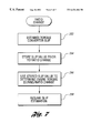
- FIG. 7 is a flowchart illustrating alternative control logic for determining a desired engine torque during a ratio change according to the present invention
- FIG. 8 is a graph illustrating representative values of a transmission oil pump for use in determining desired engine torque according to the present invention.
- FIG. 9 is a graph illustrating representative values for torque converter multiplication based on speed ratio for used in determining a desired engine torque according to the present invention.
- FIG. 10 is a graph illustrating representative values of transmission spin loss for use in determining a requested engine torque according to the present invention.
- FIG. 11 is a graph illustrating representative values of transmission torque proportional losses for use in determining desired engine torque according to the present invention.
- FIGS. 12A-12D illustrate engine torque modulation during a ratio change based on a desired engine torque calculation according to the present invention.
- FIG. 1 provides a block diagram illustrating operation of a system or method for determining desired engine torque based on wheel torque for use in controlling a powertrain according to the present invention.
- System 10 includes a vehicular powertrain 12 having an internal combustion engine 14 coupled to an automatic transmission 16 .
- Powertrain 12 may also include a controller 18 in communication with engine 14 and transmission 16 for providing various information and control functions.
- Engine 14 is connected to transmission 16 via crankshaft 20 which is connected to transmission pump 22 and/or torque converter 24 .
- torque converter 24 is a hydrodynamic torque converter including a pump or impeller 26 which is selectively fluidly coupled to a turbine 28 .
- Torque converter 24 may also include a frictional converter clutch or bypass clutch 30 which provides a selective frictional coupling between turbine shaft 32 and input shaft 34 .
- Automatic transmission 16 includes a plurality of input-to-output ratios or gear ratios effected by various gears, indicated generally by reference numeral 36 , and associated frictional elements such as clutches, bands, and the like, as well known in the art.
- Gears 36 provide selective reduction or multiplication ratios between turbine shaft 32 and output shaft 38 .
- Automatic transmission 16 is preferably electronically controlled via one or more shift solenoids, indicated generally by reference numeral 40 , and a converter clutch control (CC) 41 to select an appropriate gear ratio based on current operating conditions.
- Transmission 16 also preferably includes an actuator for controlling pump pressure (PP) 42 (or line pressure), in addition to a shift lever position sensor (PRN) 44 to provide an indication of the operator's selected gear or driving mode, such as drive, reverse, park, etc.
- a line pressure sensor (LP) 46 can be provided to facilitate closed loop feedback control of the hydraulic line pressure during shifting or ratio changing.
- output shaft 38 may be coupled to one or more axles 48 via a final drive reduction or differential 50 which may include one or more gears, as indicated generally by reference numeral 52 .
- Each axle 48 may include two or more wheels 54 having corresponding wheel speed sensors 56 .
- powertrain 12 preferably includes a plurality of sensors, indicated generally by reference numeral 60 , in communication with corresponding input ports 62 of controller 18 to sense or monitor the current operating and ambient conditions of powertrain 12 .
- a plurality of actuators, indicated generally by reference numeral 64 communicate with controller 18 via output ports 66 to effect control of powertrain 12 in response to commands generated by controller 18 .
- the sensors preferably include a throttle valve position sensor (TPS) 68 which monitors the position of throttle valve 70 which is disposed within intake 72 .
- TPS throttle valve position sensor
- a mass air flow sensor (MAF) 74 provides an indication of the air mass flowing through intake 72 .
- a temperature sensor (TMP) 76 provides an indication of the engine temperature which may include engine coolant temperature or engine oil temperature, for example.
- an engine speed sensor (RPM) 80 monitors rotational speed of crankshaft 20 .
- a turbine speed sensor 82 monitors the rotational speed of the turbine 28 of torque converter 24 .
- Another rotational speed sensor, vehicle speed sensor (VSS) 84 provides an indication of the speed of output shaft 38 which may be used to determine the vehicle speed based on the ratio of differential 50 and the size of wheels 54 .
- wheel speed sensors (WS 1 and WS 2 ) 56 may be used to provide an indication of the vehicle speed as well.
- various sensors may be omitted or alternative sensors provided which generate signals indicative of related sensed parameters. Values corresponding to ambient or operating conditions may be inferred or calculated using one or more of the sensed parameters without departing from the spirit or scope of the present invention.
- An accelerator pedal 58 is manipulated by the driver to control the output of powertrain 12 .
- a pedal position sensor 59 provides an indication of the position of accelerator pedal 58 , preferably in the form of counts. In one embodiment, an increasing number of counts indicates a request for increased power output. Preferably, redundant position sensors are used with at least one position sensor having a negative slope such that a decreasing number of counts corresponds to a request for increased power output.
- a manifold absolute pressure (MAP) sensor, or equivalent, may be used to provide an indication of the current barometric pressure.
- Actuators 64 are used to provide control signals or to effect movement of various devices in powertrain 12 .
- Actuators 64 may include actuators for timing and metering fuel (FUEL) 90 , controlling ignition angle or timing (SPK) 92 , setting the amount of exhaust gas recirculation (EGR) 94 , and adjusting the intake air using throttle valve 70 with an appropriate servomotor or actuator (TVA) 96 .
- automatic transmission 16 may be selectively controlled by controlling transmission pump or line pressure using an appropriate actuator (PP) 42 in combination with shift solenoids (SS 1 and SS 2 ) 40 which are used to select an appropriate gear ratio, and a converter clutch actuator or solenoid (CC) 41 used to lock, unlock or control slip of the torque converter clutch 30 .
- a temperature sensor 106 is provided to determine the transmission oil temperature (TOT).
- Controller 18 is preferably a microprocessor-based controller which provides integrated control of engine 14 and transmission 16 of powertrain 12 .
- Controller 18 includes a microprocessor 110 in communication with input ports 62 , output ports 66 , and computer readable media 112 via a data/control bus 114 .
- Computer readable media 112 may include various types of volatile and nonvolatile memory such as random access memory (RAM) 116 , read-only memory (ROM) 118 , and keep-alive memory (KAM) 119 .
- RAM random access memory
- ROM read-only memory
- KAM keep-alive memory
- Computer readable media 112 include stored data representing instructions executable by microprocessor 110 to implement the method for determining a desired engine torque based on a desired wheel torque according to the present invention.
- FIG. 2 provides a block diagram for a modular control architecture including determination of desired engine torque from desired wheel torque according to the present invention.
- a driver demand is interpreted as represented by block 120 based on the vehicle speed 122 accelerator pedal position 124 and barometric pressure 126 .
- the driver demand wheel torque (TQWH_DD) is provided as an input to block 130 which arbitrates the final wheel torque among various other torque requesters, indicated generally by reference numeral 132 .
- torque requesters may include, for example, a cruise control torque 134 , a traction assist torque 136 , and/or a vehicle speed limiting torque 138 .
- Block 130 selects the appropriate torque depending upon the current operating conditions and provides this final wheel torque (TQ_WHEEL) to block 140 which performs a number of functions including scheduling the gear ratio and ratio changes.
- Block 140 preferably includes determination of a torque converter slip, and calculation of a desired engine torque based on the final desired wheel torque according to the present invention. Inputs used in these determinations include vehicle speed 122 , barometric pressure 126 , current gear ratio 142 , current torque converter slip 144 , and bypass clutch duty cycle 145 . Determination of the desired engine torque is explained in greater detail below.
- the engine torque requested from block 140 is arbitrated with various other engine torque limiting functions 146 as represented by block 150 .
- Transmission controller 152 may also request torque limiting or modulation to provide cancellation of the inertia phase to improve shift feel.
- Transmission controller 152 communicates with transmission solenoid control module 154 which energizes the appropriate shift solenoids to effect the ratio change. Solenoid control module 154 preferably dynamically controls the line pressure via transmission pump pressure actuator 42 during a ratio change to improve shift feel. Alternatively, the apply and release pressures for individual clutches or shifting elements may be controlled during the ratio change to further improve shift feel.
- Transmission controller 152 is also in communication with bypass clutch controller 155 which controls the duty cycle of the torque converter bypass clutch to control the state of the clutch.
- the final engine torque determined by block 150 is communicated as a desired engine torque to engine controller 156 .
- the engine controller determines the appropriate air flow, spark, EGR, and fuel as represented by blocks 158 , 160 , 162 , and 164 , respectively, to achieve the desired engine torque, such that the wheel torque approaches the desired wheel torque.
- the present invention is described with reference to a desired wheel torque, one of ordinary skill in the art will recognize that the present invention could be easily applied to a system which uses a desired tractive effort or wheel power while providing similar benefits in fuel economy, modularity, and drivability.
- the driver request for powertrain output as indicated by accelerator pedal position can be interpreted as a request for wheel power, tractive effort, or engine torque (for manual transmission applications), depending upon the particular application.
- FIG. 3 a flowchart illustrating control logic of one embodiment of a system or method according to the present invention is shown.
- the flowchart illustrated in FIG. 3 may represent any of a number of known processing strategies such as event-driven, interrupt-driven, multi-tasking, multi-threading, and the like. As such, various steps or functions illustrated may be performed in the sequence illustrated, in parallel, or in some cases omitted. Likewise, the order of processing is not necessarily required to achieve the objects, features, and advantages of the invention, but is provided for ease of illustration and description.
- the control logic is implemented in software which is executed by a microprocessor-based controller. Of course, the control logic may be implemented in software, hardware, or a combination of software and hardware.
- the flowcharts of FIGS. 3-5 illustrate one “loop” and are preferably repeated at predetermined time intervals as known by those of skill in the art.
- Block 200 of FIG. 3 represents determination of a desired wheel torque.
- wheel torque is determined based on accelerator pedal position, vehicle speed, and barometric pressure.
- This step may also include determining another output parameter which is then converted or used to determine the desired wheel torque.
- the desired powertrain output may be based at least in part on the position of an accelerator pedal where the desired powertrain output represents a desired wheel power, tractive effort, engine torque, or the like.
- the powertrain output parameter may be used to determine the desired engine torque with appropriate adjustments to the following steps.
- the desired wheel torque is arbitrated with other wheel torque requests as illustrated and described with reference to FIG. 2 .
- the current engine speed and turbine speed are determined as represented by block 202 .
- the engine speed and turbine speed are determined using appropriate sensors.
- an estimation or calculation may be performed to determine the speed.
- turbine speed may be estimated using the engine speed and a torque converter slip calculation.
- the torque losses due to the automatic transmission can be separated into a spin loss term and a torque proportional loss.
- the spin loss is preferably characterized by the particular gear and turbine speed.
- turbine speed refers to the input shaft speed of the gearbox or, alternatively, the output speed of the torque converter.
- the torque proportional loss is essentially a slope which varies as a function of the current gear and turbine speed. As such, the total gearbox loss can be written as:
- T t represents the turbine output torque
- N t represents the turbine speed
- f 1 and f 2 are functions represented by values which are preferably stored in corresponding lookup tables.
- the gearbox losses may be determined according to:
- a transmission spin loss is based on a first function of turbine speed and the currently selected gear while the torque proportional loss is based on a second function of the turbine speed and the currently selected gear.
- the spin loss and torque proportional loss are adjusted for variations in transmission oil temperature (TOT) because the losses due to cold TOT may be significant. This may be accomplished by incorporating TOT into the lookup table values, or by including a separate lookup table with a scaling factor.
- TOT transmission oil temperature
- the currently selected gear and associated gear ratio are determined as represented by block 204 .
- the value for the current gear, or alternatively the current gear ratio is used along with the turbine speed (estimated or actual) to determine a transmission spin loss as represented by block 206 .
- the spin loss values are stored in a lookup table which corresponds to the current gear and is accessed or indexed by the turbine speed as described above. Determination of the torque proportional loss is represented by block 208 of FIG. 3 .
- These values are also preferably stored in a lookup table with a separate set of values for each of the available gears or gear ratios.
- the lookup table corresponding to the current gear or gear ratio is preferably accessed or indexed by turbine speed, or an equivalent value.
- the torque loss due to the transmission oil pump may be described as a function of engine speed and transmission line pressure (LP).
- a value representing the transmission pump loss is determined as represented by block 210 .
- the values for transmission pump loss are preferably stored in a lookup table, which, for transmission oil pump losses, is indexed by engine speed and line pressure.
- a torque converter multiplication factor is determined as represented by block 212 .
- the torque converter multiplies or increases the engine torque delivered to the input of the transmission gearbox.
- the converter multiplication is determined based on the speed ratio (turbine speed/engine speed).
- the multiplication factors or values are preferably stored in a lookup table which, in this case, is indexed by the speed ratio.
- a more complex determination which incorporates terms for the torque converter clutch (bypass clutch) is illustrated and described with reference to FIG. 4 .
- Block 214 of FIG. 3 represents determination of a scaling factor based on the currently selected gear. This factor may be used to fine-tune or calibrate the engine torque determination for any additional losses which may not be included in the torque loss terms described above. The engine torque is then determined based on the transmission spin loss, torque proportional loss, pump loss, gear ratio, final drive ratio, converter multiplication, and scaling factor as represented by block 216 .
- T e represents the desired engine torque
- N e represents engine speed
- P l represents line pressure
- T w represents the desired wheel torque
- GRRAT represents the currently selected gear ratio
- FDR represents the final drive ratio or differential ratio, which may or may not account for efficiency of the differential.
- fn_spinx represents the transmission spin loss
- fn_tq_px represents the torque proportional loss
- N t represents the turbine speed
- tq_mult_x represents the scaling factor where x in each of the functions represents a particular lookup table for the currently selected gear.
- the engine torque determined by block 216 is then used to control the powertrain such that the wheel torque approaches the desired wheel torque.
- a alternative embodiment for determining engine torque using a power calculation and a ratio calculation is illustrated and described with reference to FIG. 5 .
- FIG. 4 a flowchart illustrating an alternative method for determining the torque converter multiplication represented by block 212 of FIG. 3 is shown.
- This approach incorporates a more sophisticated model which includes a capacity term and a friction term to represent losses associated with the torque converter clutch during partial engagement.
- a torque converter clutch capacity term is determined as represented by block 230 .
- the capacity term is a function of the torque converter clutch solenoid duty cycle, engine speed (RPM), turbine speed (N T ), a time delay corresponding to the prestroke delay of the hydraulic and mechanical converter system, and a time constant representing the response time of the hydraulic system.
- a friction term is then determined as represented by block 232 .
- the friction term is a function of the converter clutch solenoid duty cycle, a proportionality constant (K), and the converter slip, i.e. the difference between engine speed and turbine speed.
- K proportionality constant
- the adjusted or compensated torque converter multiplication is then preferably determined according to:
- T e max( 0 ,T t -T clutch )/fn(N t /N e )+min(T clutch ,T t )+friction (4)
- min represents a function which selects the minimum or lowest value of the parenthetical terms and max is a function which selects the maximum of the parenthetical terms.
- FIG. 5 An alternative strategy for determining the desired engine torque according to the present invention is illustrated in FIG. 5 .
- This strategy uses either a power calculation or a gear ratio calculation to determine the desired engine torque, depending upon the current vehicle speed. Because the power calculation includes a term representing the wheel speed (WS), it would provide a zero solution when the vehicle is stationary. As such, the power calculation provides a useful result only when the vehicle speed exceeds a corresponding threshold as represented by block 240 .
- the power calculation, represented by block 242 determines engine torque as a function of wheel speed, wheel torque, engine speed (RPM), and turbine speed (TS).
- a desired engine torque is determined according to:
- T e [T w *N wheel ]/[fn(N t /N e )*N t ], (5)
- T e represents the engine torque
- T w represents the wheel torque
- N wheel represents the wheel speed
- N t represents the turbine speed
- a gear ratio-based calculation is used as represented by block 244 .
- the ratio calculation determines engine torque as a function of wheel torque, gear ratio, engine speed, and turbine speed.
- the engine torque is determined according to:
- T e T w /[GRRAT*FDR*fn(N t /N e )] (6)
- T e represents the desired engine torque
- T w represents the desired wheel torque
- GRRAT represents the gear ratio
- FDR represents the final drive ratio
- N t represents the turbine speed
- N e represents the engine speed.
- the power calculation and ratio calculation may be modified to determine the engine torque using the torque converter slip.
- T e [T w *N wheel ]/[fn((N e ⁇ SLIP)/N e )*(N e ⁇ SLIP)] (7)
- FIGS. 6 and 7 are flowcharts representing alternative methods for determining the desired engine torque during a ratio change according to the present invention. Either strategy may be used with one or both of the alternative strategies for determining engine torque described above.
- the first strategy illustrated in FIG. 6, calculates the desired engine torque for the currently selected gear as represented by block 246 .
- a second engine'torque is calculated based on the target gear as represented by block 248 .
- the resulting desired engine torque is then determined based on an interpolation between the first and second engine torque values calculated by blocks 246 and 248 as represented by block 250 .
- Turbine speed is used to interpolate between the two values for engine torque by comparing the actual or estimated turbine speed to the expected turbine speed for the current and target gears or gear ratios.
- This strategy may be preferred for some applications in that it accommodates integration of relatively complex expressions for engine torque, it is not susceptible to delays in gear ratio, and the same expression may be used to calculate the engine torque over the entire vehicle speed range.
- FIG. 7 An alternative method for calculating the engine torque during a ratio change is illustrated in FIG. 7 .
- This alternative, or second strategy is particularly useful for applications where the turbine speed or slip cannot be accurately determined during a ratio change or gear shift.
- This strategy is based on a sample-and-hold technique.
- the value for the torque converter slip or turbine speed is determined as represented by block 252 .
- This value is stored or held constant for a predetermined period of time as represented by block 254 .
- the slip or turbine speed is again measured or calculated to determine the “actual” value as represented by block 258 .
- the sudden change between the engine torque calculated using the held value and the engine torque calculated using the actual value which occurs upon expiration of the predetermined time can be used to improve shift quality, if appropriately synchronized with the ratio change, i.e., synchronized with the inertia phase to request an engine torque reduction which cancels the inertia of the shift.
- FIG. 8 provides representative values for transmission oil pump losses for use in determination of a desired engine torque according to the present invention.
- the graph of FIG. 8 plots torque loss as a function of transmission pump speed for a representative operating oil temperature of 200° F.
- Line 260 represents a line pressure of 200 psi with a torque loss value ranging between about 3 and 7 ft.-lbs.
- Lines 262 , 264 , and 266 represent the associated losses for line pressures corresponding to 150, 100, and 60 psi, respectively.
- These values are preferably stored in a lookup table which is referenced by pump or engine speed, and may also be referenced by, or adjusted by, transmission oil temperature (TOT).
- TOT transmission oil temperature
- FIG. 9 illustrates representative values for the torque converter multiplication factor used in determining desired engine torque according to the present invention.
- the values are stored in a look-up table which is indexed or referenced by the speed ratio.
- Line 270 represents the torque converter multiplication factors for an input torque of about 35 ft.-lbs.
- Lines 272 and 274 represent the torque converter multiplication factors for input torques of about 100 and 200 ft.-lbs., respectively.
- FIG. 10 illustrates representative values for transmission spin losses used in determining a desired engine torque according to the present invention.
- the transmission spin loss values are stored in lookup tables associated with each of the available gears or gear ratios.
- the graph of FIG. 10 plots torque loss (ft.-lbs.) as a function of turbine shaft speed.
- Line 280 represents the spin loss values for first gear in a representative application.
- Line 282 represents the transmission spin loss values for second gear, while lines 284 and 286 represent the transmission spin losses for third gear and fourth gear, respectively.
- FIG. 11 Representative values for torque proportional losses used in determining a desired engine torque according to the present invention are shown in FIG. 11 .
- the graph of FIG. 11 plots torque loss (ft.-lbs.) as a function of turbine shaft RPM for various torques.
- Lines 290 , 292 , and 294 represent the torque proportional losses for input torques corresponding to 718 , 500 , and 200 , respectively.
- the remaining lines, represented generally by reference numeral 296 correspond to torque proportional losses for torques of 100-0 ft.-lbs.
- FIGS. 12A-12D illustrate the operation of torque modulation during a ratio change to improve shift feel.
- torque modulation is accomplished using a spark retard during the inertia phase of the shift.
- the spark retard may be determined using a torque ratio calculation based on the desired engine torque determined according to one of the strategies described above.
- the torque ratio is determined according to:
- T e represents the desired steady state engine torque (not accounting for engine inertia torque)
- dNdtI represents the time derivative of engine speed
- I e represents engine inertia.
- the corresponding spark retard is preferably calculated according to:
- G is a calibratable gain used to tune performance.
- Line 310 of FIG. 12 a represents the desired wheel torque as a function of time.
- Line 312 of FIG. 12 a represents the actual wheel torque.
- FIG. 12 b illustrates the engine RPM on the same time scale.
- FIG. 12 c illustrates the time derivative of the engine RPM as represented by line 330 .
- FIG. 12 d illustrates the spark retard calculated in accordance with equation (10) based on the desired engine torque determined according to the present invention. As illustrated in FIG. 12 a , the torque modulation using the desired engine torque has been effective to substantially reduce or eliminate the inertia torque during the 1-2 shift.
Abstract
Description

Claims (24)
Priority Applications (4)
| Application Number | Priority Date | Filing Date | Title |
|---|---|---|---|
| US09/306,307 US6434466B1 (en) | 1999-05-06 | 1999-05-06 | System and method for determining engine torque for controlling a powertrain |
| DE10014629A DE10014629A1 (en) | 1999-05-06 | 2000-03-24 | System and method for determining the engine torque for controlling the drive train of a motor vehicle |
| GB0227995A GB2380776B (en) | 1999-05-06 | 2000-05-03 | System and method for determining engine torque for controlling a powertrain |
| GB0010540A GB2350163B (en) | 1999-05-06 | 2000-05-03 | System and method for determining engine torque for controlling a powertrain |
Applications Claiming Priority (1)
| Application Number | Priority Date | Filing Date | Title |
|---|---|---|---|
| US09/306,307 US6434466B1 (en) | 1999-05-06 | 1999-05-06 | System and method for determining engine torque for controlling a powertrain |
Publications (1)
| Publication Number | Publication Date |
|---|---|
| US6434466B1 true US6434466B1 (en) | 2002-08-13 |
Family
ID=23184721
Family Applications (1)
| Application Number | Title | Priority Date | Filing Date |
|---|---|---|---|
| US09/306,307 Expired - Fee Related US6434466B1 (en) | 1999-05-06 | 1999-05-06 | System and method for determining engine torque for controlling a powertrain |
Country Status (3)
| Country | Link |
|---|---|
| US (1) | US6434466B1 (en) |
| DE (1) | DE10014629A1 (en) |
| GB (1) | GB2350163B (en) |
Cited By (41)
| Publication number | Priority date | Publication date | Assignee | Title |
|---|---|---|---|---|
| US20020029136A1 (en) * | 2000-08-11 | 2002-03-07 | Honda Giken Kogyo Kabushiki Kaisha | Simulator for automatic vehicle transmission controllers |
| US20030040403A1 (en) * | 2001-08-21 | 2003-02-27 | Deere & Company, A Delaware Corporation | System and method for reducing vehicle bouncing |
| US20040014563A1 (en) * | 2002-07-19 | 2004-01-22 | Deere & Company, A Delaware Corporation | Transmission shift control with engine torque control |
| US6701228B2 (en) * | 2002-05-31 | 2004-03-02 | Quantum Engineering, Inc. | Method and system for compensating for wheel wear on a train |
| EP1429011A1 (en) * | 2002-12-13 | 2004-06-16 | Renault S.A. | Engine torque control method and system for an automotive vehicle |
| US20040259684A1 (en) * | 2003-06-18 | 2004-12-23 | Kresse John P. | Motor vehicle powertrain control method for low traction conditions |
| US6847879B1 (en) | 2004-01-30 | 2005-01-25 | Daimlerchrysler Corporation | Method of controlling torque converter clutch slip |
| FR2866284A1 (en) * | 2004-02-16 | 2005-08-19 | Peugeot Citroen Automobiles Sa | Traction chain driving device for motor vehicle, has control unit with driver interface to calculate wheel torque based on vehicle speed and acceleration, and calculate gearing reduction ratio based on torque, for calculating engine torque |
| US20050261107A1 (en) * | 2001-09-06 | 2005-11-24 | Martin Lankes | Adjustment of the speed of a motor vehicle with an automatic gearbox |
| US20060020383A1 (en) * | 2004-07-23 | 2006-01-26 | Caterpillar Inc. | Systems for controlling work machine power |
| US20060021811A1 (en) * | 2004-07-30 | 2006-02-02 | Ford Motor Company | Wheel torque estimation in a powertrain for a hybrid electric vehicle |
| WO2006040302A1 (en) * | 2004-10-08 | 2006-04-20 | Robert Bosch Gmbh | Method and device for controlling a drive unit |
| US20060161325A1 (en) * | 2005-01-18 | 2006-07-20 | Hong Jiang | Automated manual transmission launch control |
| US20060173599A1 (en) * | 2005-01-31 | 2006-08-03 | Caterpillar Inc. | Retarding system implementing transmission control |
| EP1688620A1 (en) * | 2003-11-26 | 2006-08-09 | Hitachi Construction Machinery Co., Ltd. | Traveling hydraulic working machine |
| US20060293149A1 (en) * | 2005-06-23 | 2006-12-28 | Caterpillar Inc. | Systems and methods for controlling a powertrain |
| US7269491B2 (en) * | 2002-05-16 | 2007-09-11 | General Motors Corporation | Cross-checking processors for powertrain control systems using a dedicated serial data link |
| US20070299564A1 (en) * | 2006-06-27 | 2007-12-27 | Sauer-Danfoss Inc. | Method of operating a vehicle apparatus comprising the same |
| US7319927B1 (en) * | 2005-05-12 | 2008-01-15 | Kelsey-Hayes Company | Constant speed control system |
| US20080045380A1 (en) * | 2004-09-22 | 2008-02-21 | Zf Friedrichshafen Ag | Placing an Automatic Synchronized Transmission into a Starting Speed |
| US20100286877A1 (en) * | 2009-05-05 | 2010-11-11 | Ford Global Technologies, Llc | Temperature Dependent Minimum Transmission Input Speed |
| US20100324789A1 (en) * | 2007-03-16 | 2010-12-23 | Toyota Jidosha Kabushiki Kaisha | Vehicle driving force control device |
| US20110118955A1 (en) * | 2009-11-19 | 2011-05-19 | Gm Global Technology Operations, Inc. | System and method for controlling engine torque |
| US20110190996A1 (en) * | 2010-02-03 | 2011-08-04 | Honda Motor Co., Ltd. | Clutch controlling apparatus |
| US20110197694A1 (en) * | 2008-10-23 | 2011-08-18 | Zf Friedrichshafen Ag | Method for reversing the direction of travel of a vehicle |
| US20120186675A1 (en) * | 2011-01-25 | 2012-07-26 | GM Global Technology Operations LLC | Method and apparatus to detect the presence of hydraulic pressure in a transmission |
| US20120259522A1 (en) * | 2010-02-23 | 2012-10-11 | Honda Motor Co., Ltd. | Start clutch control device |
| US20120265421A1 (en) * | 2011-04-18 | 2012-10-18 | GM Global Technology Operations LLC | Engine control systems and methods |
| US8540604B1 (en) | 2012-03-15 | 2013-09-24 | Ford Global Technologies, Llc | Transmission control during regenerative braking |
| US20140163788A1 (en) * | 2012-12-10 | 2014-06-12 | Ford Global Technologies, Llc | Method and system for improving hybrid vehicle shifting |
| US20140191695A1 (en) * | 2013-01-08 | 2014-07-10 | Honeywell International, Inc., Patent Services M/S Ab/2B | Thermal protection method and system to maximize availability of electric drive system |
| US20160333802A1 (en) * | 2015-05-13 | 2016-11-17 | Honda Motor Co., Ltd. | Control device for internal combustion engine |
| US9677510B2 (en) | 2014-10-14 | 2017-06-13 | Ford Global Technologies, Llc | Systems and methods for transient control |
| US9869259B1 (en) * | 2016-10-05 | 2018-01-16 | GM Global Technology Operations LLC | System and method for vehicle propulsion system control |
| CN107676186A (en) * | 2017-09-27 | 2018-02-09 | 广州汽车集团股份有限公司 | A kind of engine torque control method |
| US10029672B2 (en) | 2013-03-15 | 2018-07-24 | Allison Transmission, Inc. | System and method for energy rate balancing in hybrid automatic transmissions |
| US20210300330A1 (en) * | 2020-03-26 | 2021-09-30 | Zf Friedrichshafen Ag | Method for Operating a Motor Vehicle Drive Train |
| US11181191B1 (en) | 2020-08-26 | 2021-11-23 | Ford Global Technologies, Llc | Torque ratio bounds for automatic transmissions |
| CN114687869A (en) * | 2020-12-31 | 2022-07-01 | 宝能汽车集团有限公司 | Vehicle control method and vehicle |
| US11866049B1 (en) | 2022-11-17 | 2024-01-09 | Ford Global Technologies, Llc | Powertrain torque control during a transmission shift |
| US11932254B1 (en) | 2022-10-31 | 2024-03-19 | Ford Global Technologies, Llc | Powertrain torque control during a transmission shift |
Families Citing this family (4)
| Publication number | Priority date | Publication date | Assignee | Title |
|---|---|---|---|---|
| JP3672854B2 (en) * | 2001-08-01 | 2005-07-20 | アイシン・エィ・ダブリュ株式会社 | Vehicle engine control device |
| DE10205392B4 (en) * | 2002-02-09 | 2005-12-08 | Bayerische Motoren Werke Ag | Method for testing gear ratios for the drive train of a motor vehicle |
| US7370516B2 (en) * | 2005-11-21 | 2008-05-13 | General Motors Corporation | Method for estimating transmission input torque |
| US8234049B2 (en) * | 2008-03-14 | 2012-07-31 | GM Global Technology Operations LLC | ECM security strategy for rationalizing and controlling increasing transmission torque requests above driver command |
Citations (68)
| Publication number | Priority date | Publication date | Assignee | Title |
|---|---|---|---|---|
| AU6683181A (en) | 1980-01-31 | 1982-09-16 | Mikuni Kogyo Co. Ltd. | Electronic control fuel injection system |
| US4353272A (en) | 1978-03-17 | 1982-10-12 | Robert Bosch Gmbh | Apparatus for controlling the operation of the engine-transmission assembly of a motor vehicle |
| GB2154763A (en) | 1984-02-07 | 1985-09-11 | Nissan Motor | Output torque dependent throttle control system for internal combustion engine |
| EP0206091A2 (en) | 1985-06-24 | 1986-12-30 | Honda Giken Kogyo Kabushiki Kaisha | Method for control of idle rotations of internal combustion engines |
| US4697561A (en) | 1985-04-15 | 1987-10-06 | Purdue Research Foundation | On-line engine torque and torque fluctuation measurement for engine control utilizing crankshaft speed fluctuations |
| US4730708A (en) | 1985-05-30 | 1988-03-15 | Toyota Jidosha Kabushiki Kaisha | Idling control method and system for internal combustion engine providing anti creep action |
| US4739483A (en) | 1983-08-05 | 1988-04-19 | Nippon Soken, Inc. | Automatic transmission control system for an automobile |
| US4844202A (en) * | 1987-09-28 | 1989-07-04 | Sundstrand Corporation | Lubrication system for and method of minimizing heat rejection in gearboxes |
| EP0340764A2 (en) | 1988-05-06 | 1989-11-08 | Nissan Motor Co., Ltd. | Line pressure control arrangement for automatic transmission |
| US4951627A (en) | 1988-09-16 | 1990-08-28 | Mazda Motor Corp. | Engine idling speed control system for internal combustion engine |
| EP0408767A1 (en) | 1989-01-31 | 1991-01-23 | Mitsubishi Jidosha Kogyo Kabushiki Kaisha | Engine output controller |
| EP0413031A1 (en) | 1989-01-31 | 1991-02-20 | Mitsubishi Jidosha Kogyo Kabushiki Kaisha | Output controller of internal combustion engine |
| US5029087A (en) * | 1989-07-24 | 1991-07-02 | Ford Motor Company | Electronic control system for controlling torque converter bypass clutches |
| GB2239500A (en) | 1989-12-19 | 1991-07-03 | Nissan Motor | Adaptive control of servo activating hydraulic fluid pressure for shift in automatic transmission in response to intake airflow rate and vehicle speed |
| GB2239683A (en) | 1989-12-15 | 1991-07-10 | Nissan Motor | Adaptive control of servo activating pressure for motor vehicle automatic transmission in response to intake air flow and vehicle speed |
| US5078109A (en) | 1989-01-31 | 1992-01-07 | Mitsubishi Jidosha Kogyo Kabushiki Kaisha | Engine output controlling method |
| US5086668A (en) | 1988-10-29 | 1992-02-11 | Mazda Motor Corporation | Line pressure control system for automatic transmission |
| US5213011A (en) * | 1991-04-05 | 1993-05-25 | Mazda Motor Corporation | Power transmission device for vehicle |
| EP0557299A1 (en) | 1990-11-23 | 1993-09-01 | Bosch Gmbh Robert | Method of controlling the operation of a propulsion unit consisting of an internal-combustion engine and an automatic gearbox. |
| US5245966A (en) | 1991-12-19 | 1993-09-21 | Robert Bosch Gmbh | Control system for a drive unit in motor vehicle |
| US5304102A (en) | 1991-02-21 | 1994-04-19 | Nissan Motor Co., Ltd. | Control for shift in automatic transmission |
| US5325740A (en) | 1991-08-02 | 1994-07-05 | Robert Bosch Gmbh | Arrangement for controlling the output power of a drive unit of a motor vehicle |
| US5351776A (en) | 1991-04-05 | 1994-10-04 | Robert Bosch Gmbh | Electronic system for a motor vehicle |
| US5374224A (en) | 1993-12-23 | 1994-12-20 | Ford Motor Company | System and method for controlling the transient torque output of a variable displacement internal combustion engine |
| US5377562A (en) * | 1990-09-12 | 1995-01-03 | Honda Giken Kogyo Kabushiki Kaisha | Driven wheel torque control system |
| WO1995001502A1 (en) | 1993-06-30 | 1995-01-12 | Orbital Engine Company (Australia) Pty. Limited | Engine air supply systems |
| US5385516A (en) * | 1991-12-24 | 1995-01-31 | General Motors France | Control method for managing engine torque |
| US5398544A (en) | 1993-12-23 | 1995-03-21 | Ford Motor Company | Method and system for determining cylinder air charge for variable displacement internal combustion engine |
| US5407401A (en) | 1992-02-14 | 1995-04-18 | Robert Bosch Gmbh | Arrangement of controlling the output torque of an automatic transmission |
| US5408974A (en) | 1993-12-23 | 1995-04-25 | Ford Motor Company | Cylinder mode selection system for variable displacement internal combustion engine |
| US5408966A (en) | 1993-12-23 | 1995-04-25 | Ford Motor Company | System and method for synchronously activating cylinders within a variable displacement engine |
| US5431139A (en) | 1993-12-23 | 1995-07-11 | Ford Motor Company | Air induction control system for variable displacement internal combustion engine |
| US5445125A (en) | 1994-03-16 | 1995-08-29 | General Motors Corporation | Electronic throttle control interface |
| US5460580A (en) * | 1993-05-12 | 1995-10-24 | Robert Bosch Gmbh | Method and arrangement for controlling the drive power of a drive unit of a motor vehicle |
| US5462501A (en) | 1993-04-10 | 1995-10-31 | Robert Bosch Gmbh | Method of actuating an automatic transmission |
| US5484351A (en) * | 1992-06-20 | 1996-01-16 | Robert Bosch Gmbh | Arrangement for controlling the torque to be supplied by a drive unit of a motor vehicle |
| US5501644A (en) | 1993-09-04 | 1996-03-26 | Robert Bosch Gmbh | Method and arrangement for actuating an automatic transmission |
| US5503129A (en) | 1995-05-18 | 1996-04-02 | Ford Motor Company | Apparatus and method for mode recommendation in a variable displacement engine |
| US5520159A (en) | 1994-12-09 | 1996-05-28 | Ford Motor Company | Burned gas recycling system with powertrain optimization |
| US5568795A (en) | 1995-05-18 | 1996-10-29 | Ford Motor Company | System and method for mode selection in a variable displacement engine |
| US5575257A (en) | 1993-12-18 | 1996-11-19 | Robert Bosch Gmbh | Method and device for the open-loop control of an internal-combustion engine |
| EP0749524A1 (en) | 1994-03-07 | 1996-12-27 | Robert Bosch Gmbh | Vehicle control process and device |
| US5588178A (en) | 1995-06-07 | 1996-12-31 | Mcculloch Corporation | Impeller for blower/vacuum |
| EP0754888A2 (en) | 1992-09-16 | 1997-01-22 | Hitachi, Ltd. | Axle torque estimating system |
| US5603672A (en) | 1993-10-05 | 1997-02-18 | Robert Bosch Gmbh | Method for controlling the output torque of an automatic transmission |
| US5605131A (en) | 1995-02-21 | 1997-02-25 | Honda Giken Kogyo Kabushiki Kaisha | Engine output control system for vehicle |
| US5628706A (en) * | 1992-10-23 | 1997-05-13 | Robert Bosch Gmbh | Method and arrangement for controlling the output power of a drive unit of a motor vehicle |
| US5680763A (en) | 1995-01-25 | 1997-10-28 | Robert Bosch Gmbh | System for controlling a charging of an internal combustion engine |
| GB2312970A (en) | 1996-05-11 | 1997-11-12 | Ford Motor Co | Diesel engine control |
| US5720693A (en) * | 1995-08-02 | 1998-02-24 | Jatco Corporation | Engine output control apparatus |
| GB2318105A (en) | 1996-09-12 | 1998-04-15 | Siemens Ag | Drive train control for a motor vehicle |
| US5743083A (en) | 1995-05-12 | 1998-04-28 | Robert Bosch Gmbh | Method for interrupting the metering of fuel during overrun operation of an internal combustion engine |
| US5826208A (en) * | 1994-10-26 | 1998-10-20 | Hitachi, Ltd. | Powertrain control device for a vehicle using targeted tongue generation for eliminating shift shock |
| US5875761A (en) * | 1993-12-28 | 1999-03-02 | Hitachi, Ltd. | Apparatus for and method of controlling internal combustion engine |
| US5890509A (en) * | 1997-03-31 | 1999-04-06 | Ford Global Technologies, Inc. | Hydraulic temperature compensated cooler bypass control for an automatic transmission |
| US5921885A (en) * | 1995-06-16 | 1999-07-13 | Toyota Jidosha Kabushiki Kaisha | Control system for automatic transmission |
| US5938712A (en) * | 1993-03-26 | 1999-08-17 | Hitachi, Ltd. And Hitachi Automotive Engineering Co., Ltd. | Drive shaft torque controlling apparatus for use in a vehicle having a power transmission mechanism and method therefor |
| US5951433A (en) * | 1996-12-05 | 1999-09-14 | Aisin Aw Co., Ltd. | Automatic transmission |
| US5967942A (en) * | 1997-08-12 | 1999-10-19 | Unisia Jecs Corporation | Gearshift pressure controller using torque ratio of oncoming/offgoing elements and input torque |
| US5980414A (en) * | 1997-04-25 | 1999-11-09 | General Dynamics Land Systems, Inc. | Multi-range, belt-type, continuously variable transmission |
| US6052640A (en) * | 1997-11-14 | 2000-04-18 | General Motors Corporation | Automotive torque converter slip estimation |
| US6065446A (en) * | 1996-03-28 | 2000-05-23 | Siemens Aktiengesellschaft | Method for controlling an internal combustion engine |
| US6071208A (en) * | 1998-06-22 | 2000-06-06 | Koivunen; Erkki | Compact multi-ratio automatic transmission |
| US6132336A (en) * | 1997-09-05 | 2000-10-17 | Nissan Motor Co., Ltd. | Slip control apparatus for torque converter |
| US6154702A (en) * | 1997-09-08 | 2000-11-28 | Ford Global Technologies, Inc. | Method and apparatus for estimating applied wheel torque in a motor vehicle |
| US6155954A (en) * | 1998-09-22 | 2000-12-05 | Nissan Motor Co., Ltd. | Engine output control device for hybrid vehicle |
| US6188943B1 (en) * | 1997-05-22 | 2001-02-13 | Nissan Motor Co., Ltd. | Integrated control system for electronically-controlled engine and automatic transmission |
| US6188944B1 (en) * | 1999-06-01 | 2001-02-13 | Ford Motor Company | Torque control strategy for engines with continuously variable transmission |
-
1999
- 1999-05-06 US US09/306,307 patent/US6434466B1/en not_active Expired - Fee Related
-
2000
- 2000-03-24 DE DE10014629A patent/DE10014629A1/en not_active Ceased
- 2000-05-03 GB GB0010540A patent/GB2350163B/en not_active Expired - Fee Related
Patent Citations (75)
| Publication number | Priority date | Publication date | Assignee | Title |
|---|---|---|---|---|
| US4353272A (en) | 1978-03-17 | 1982-10-12 | Robert Bosch Gmbh | Apparatus for controlling the operation of the engine-transmission assembly of a motor vehicle |
| AU6683181A (en) | 1980-01-31 | 1982-09-16 | Mikuni Kogyo Co. Ltd. | Electronic control fuel injection system |
| US4739483A (en) | 1983-08-05 | 1988-04-19 | Nippon Soken, Inc. | Automatic transmission control system for an automobile |
| GB2154763A (en) | 1984-02-07 | 1985-09-11 | Nissan Motor | Output torque dependent throttle control system for internal combustion engine |
| US4697561A (en) | 1985-04-15 | 1987-10-06 | Purdue Research Foundation | On-line engine torque and torque fluctuation measurement for engine control utilizing crankshaft speed fluctuations |
| US4730708A (en) | 1985-05-30 | 1988-03-15 | Toyota Jidosha Kabushiki Kaisha | Idling control method and system for internal combustion engine providing anti creep action |
| EP0206091A2 (en) | 1985-06-24 | 1986-12-30 | Honda Giken Kogyo Kabushiki Kaisha | Method for control of idle rotations of internal combustion engines |
| US4819596A (en) | 1985-06-24 | 1989-04-11 | Honda Giken Kogyo Kabushiki Kaisha | Method for control of idle rotations of internal combustion engine |
| US4844202A (en) * | 1987-09-28 | 1989-07-04 | Sundstrand Corporation | Lubrication system for and method of minimizing heat rejection in gearboxes |
| EP0340764A2 (en) | 1988-05-06 | 1989-11-08 | Nissan Motor Co., Ltd. | Line pressure control arrangement for automatic transmission |
| US4951627A (en) | 1988-09-16 | 1990-08-28 | Mazda Motor Corp. | Engine idling speed control system for internal combustion engine |
| US5086668A (en) | 1988-10-29 | 1992-02-11 | Mazda Motor Corporation | Line pressure control system for automatic transmission |
| EP0408767A1 (en) | 1989-01-31 | 1991-01-23 | Mitsubishi Jidosha Kogyo Kabushiki Kaisha | Engine output controller |
| EP0413031A1 (en) | 1989-01-31 | 1991-02-20 | Mitsubishi Jidosha Kogyo Kabushiki Kaisha | Output controller of internal combustion engine |
| US5069181A (en) | 1989-01-31 | 1991-12-03 | Mitsubishi Jidosha Kogyo Kabushiki Kaisha | Output control apparatus for an internal combustion engine |
| US5078109A (en) | 1989-01-31 | 1992-01-07 | Mitsubishi Jidosha Kogyo Kabushiki Kaisha | Engine output controlling method |
| US5029087A (en) * | 1989-07-24 | 1991-07-02 | Ford Motor Company | Electronic control system for controlling torque converter bypass clutches |
| GB2239683A (en) | 1989-12-15 | 1991-07-10 | Nissan Motor | Adaptive control of servo activating pressure for motor vehicle automatic transmission in response to intake air flow and vehicle speed |
| US5109732A (en) | 1989-12-15 | 1992-05-05 | Nissan Motor Co., Ltd. | Adaptive control of servo activating pressure for motor vehicle automatic transmission |
| GB2239500A (en) | 1989-12-19 | 1991-07-03 | Nissan Motor | Adaptive control of servo activating hydraulic fluid pressure for shift in automatic transmission in response to intake airflow rate and vehicle speed |
| US5377562A (en) * | 1990-09-12 | 1995-01-03 | Honda Giken Kogyo Kabushiki Kaisha | Driven wheel torque control system |
| EP0557299A1 (en) | 1990-11-23 | 1993-09-01 | Bosch Gmbh Robert | Method of controlling the operation of a propulsion unit consisting of an internal-combustion engine and an automatic gearbox. |
| US5304102A (en) | 1991-02-21 | 1994-04-19 | Nissan Motor Co., Ltd. | Control for shift in automatic transmission |
| US5213011A (en) * | 1991-04-05 | 1993-05-25 | Mazda Motor Corporation | Power transmission device for vehicle |
| US5351776A (en) | 1991-04-05 | 1994-10-04 | Robert Bosch Gmbh | Electronic system for a motor vehicle |
| US5325740A (en) | 1991-08-02 | 1994-07-05 | Robert Bosch Gmbh | Arrangement for controlling the output power of a drive unit of a motor vehicle |
| US5245966A (en) | 1991-12-19 | 1993-09-21 | Robert Bosch Gmbh | Control system for a drive unit in motor vehicle |
| US5385516A (en) * | 1991-12-24 | 1995-01-31 | General Motors France | Control method for managing engine torque |
| US5407401A (en) | 1992-02-14 | 1995-04-18 | Robert Bosch Gmbh | Arrangement of controlling the output torque of an automatic transmission |
| US5484351A (en) * | 1992-06-20 | 1996-01-16 | Robert Bosch Gmbh | Arrangement for controlling the torque to be supplied by a drive unit of a motor vehicle |
| EP0754888A2 (en) | 1992-09-16 | 1997-01-22 | Hitachi, Ltd. | Axle torque estimating system |
| US5628706A (en) * | 1992-10-23 | 1997-05-13 | Robert Bosch Gmbh | Method and arrangement for controlling the output power of a drive unit of a motor vehicle |
| US5938712A (en) * | 1993-03-26 | 1999-08-17 | Hitachi, Ltd. And Hitachi Automotive Engineering Co., Ltd. | Drive shaft torque controlling apparatus for use in a vehicle having a power transmission mechanism and method therefor |
| US5462501A (en) | 1993-04-10 | 1995-10-31 | Robert Bosch Gmbh | Method of actuating an automatic transmission |
| US5460580A (en) * | 1993-05-12 | 1995-10-24 | Robert Bosch Gmbh | Method and arrangement for controlling the drive power of a drive unit of a motor vehicle |
| US5606951A (en) | 1993-06-30 | 1997-03-04 | Orbital Engine Company (Australia) Pty. Limited | Engine air supply systems |
| WO1995001502A1 (en) | 1993-06-30 | 1995-01-12 | Orbital Engine Company (Australia) Pty. Limited | Engine air supply systems |
| US5501644A (en) | 1993-09-04 | 1996-03-26 | Robert Bosch Gmbh | Method and arrangement for actuating an automatic transmission |
| US5603672A (en) | 1993-10-05 | 1997-02-18 | Robert Bosch Gmbh | Method for controlling the output torque of an automatic transmission |
| US5575257A (en) | 1993-12-18 | 1996-11-19 | Robert Bosch Gmbh | Method and device for the open-loop control of an internal-combustion engine |
| US5437253A (en) | 1993-12-23 | 1995-08-01 | Ford Motor Company | System and method for controlling the transient torque output of a variable displacement internal combustion engine |
| US5408974A (en) | 1993-12-23 | 1995-04-25 | Ford Motor Company | Cylinder mode selection system for variable displacement internal combustion engine |
| US5398544A (en) | 1993-12-23 | 1995-03-21 | Ford Motor Company | Method and system for determining cylinder air charge for variable displacement internal combustion engine |
| US5374224A (en) | 1993-12-23 | 1994-12-20 | Ford Motor Company | System and method for controlling the transient torque output of a variable displacement internal combustion engine |
| US5408966A (en) | 1993-12-23 | 1995-04-25 | Ford Motor Company | System and method for synchronously activating cylinders within a variable displacement engine |
| US5431139A (en) | 1993-12-23 | 1995-07-11 | Ford Motor Company | Air induction control system for variable displacement internal combustion engine |
| US5875761A (en) * | 1993-12-28 | 1999-03-02 | Hitachi, Ltd. | Apparatus for and method of controlling internal combustion engine |
| EP0749524A1 (en) | 1994-03-07 | 1996-12-27 | Robert Bosch Gmbh | Vehicle control process and device |
| US5692471A (en) | 1994-03-07 | 1997-12-02 | Robert Bosch Gmbh | Method and arrangement for controlling a vehicle |
| US5445125A (en) | 1994-03-16 | 1995-08-29 | General Motors Corporation | Electronic throttle control interface |
| US5826208A (en) * | 1994-10-26 | 1998-10-20 | Hitachi, Ltd. | Powertrain control device for a vehicle using targeted tongue generation for eliminating shift shock |
| US5520159A (en) | 1994-12-09 | 1996-05-28 | Ford Motor Company | Burned gas recycling system with powertrain optimization |
| US5680763A (en) | 1995-01-25 | 1997-10-28 | Robert Bosch Gmbh | System for controlling a charging of an internal combustion engine |
| US5605131A (en) | 1995-02-21 | 1997-02-25 | Honda Giken Kogyo Kabushiki Kaisha | Engine output control system for vehicle |
| US5743083A (en) | 1995-05-12 | 1998-04-28 | Robert Bosch Gmbh | Method for interrupting the metering of fuel during overrun operation of an internal combustion engine |
| US5503129A (en) | 1995-05-18 | 1996-04-02 | Ford Motor Company | Apparatus and method for mode recommendation in a variable displacement engine |
| US5568795A (en) | 1995-05-18 | 1996-10-29 | Ford Motor Company | System and method for mode selection in a variable displacement engine |
| US5588178A (en) | 1995-06-07 | 1996-12-31 | Mcculloch Corporation | Impeller for blower/vacuum |
| US5921885A (en) * | 1995-06-16 | 1999-07-13 | Toyota Jidosha Kabushiki Kaisha | Control system for automatic transmission |
| US5720693A (en) * | 1995-08-02 | 1998-02-24 | Jatco Corporation | Engine output control apparatus |
| US6065446A (en) * | 1996-03-28 | 2000-05-23 | Siemens Aktiengesellschaft | Method for controlling an internal combustion engine |
| GB2312970A (en) | 1996-05-11 | 1997-11-12 | Ford Motor Co | Diesel engine control |
| GB2318105A (en) | 1996-09-12 | 1998-04-15 | Siemens Ag | Drive train control for a motor vehicle |
| US6188945B1 (en) * | 1996-09-12 | 2001-02-13 | Siemens Aktiengesellschaft | Drive train control for a motor vehicle |
| US5951433A (en) * | 1996-12-05 | 1999-09-14 | Aisin Aw Co., Ltd. | Automatic transmission |
| US5890509A (en) * | 1997-03-31 | 1999-04-06 | Ford Global Technologies, Inc. | Hydraulic temperature compensated cooler bypass control for an automatic transmission |
| US5980414A (en) * | 1997-04-25 | 1999-11-09 | General Dynamics Land Systems, Inc. | Multi-range, belt-type, continuously variable transmission |
| US6188943B1 (en) * | 1997-05-22 | 2001-02-13 | Nissan Motor Co., Ltd. | Integrated control system for electronically-controlled engine and automatic transmission |
| US5967942A (en) * | 1997-08-12 | 1999-10-19 | Unisia Jecs Corporation | Gearshift pressure controller using torque ratio of oncoming/offgoing elements and input torque |
| US6132336A (en) * | 1997-09-05 | 2000-10-17 | Nissan Motor Co., Ltd. | Slip control apparatus for torque converter |
| US6154702A (en) * | 1997-09-08 | 2000-11-28 | Ford Global Technologies, Inc. | Method and apparatus for estimating applied wheel torque in a motor vehicle |
| US6052640A (en) * | 1997-11-14 | 2000-04-18 | General Motors Corporation | Automotive torque converter slip estimation |
| US6071208A (en) * | 1998-06-22 | 2000-06-06 | Koivunen; Erkki | Compact multi-ratio automatic transmission |
| US6155954A (en) * | 1998-09-22 | 2000-12-05 | Nissan Motor Co., Ltd. | Engine output control device for hybrid vehicle |
| US6188944B1 (en) * | 1999-06-01 | 2001-02-13 | Ford Motor Company | Torque control strategy for engines with continuously variable transmission |
Non-Patent Citations (3)
| Title |
|---|
| "Hierarchial Control Strategy of Powertrain Functions", by H.M. Streib et al, 24. FISITA Congress, London Jun. 7-11, 1992, pp. 1-11. |
| "Torque-Based System Structure of the Electronic Engine Management System (ME7) as a New Base for Drive Train Systems", by J. Gerhardt et al, 6. Aachener Kolloquim Fahrzeug- und Motorentechik ′97, Oct. 22, 1997, pp. 817-849. |
| "Torque-Based System Structure of the Electronic Engine Management System (ME7) as a New Base for Drive Train Systems", by J. Gerhardt et al, 6. Aachener Kolloquim Fahrzeug- und Motorentechik '97, Oct. 22, 1997, pp. 817-849. |
Cited By (80)
| Publication number | Priority date | Publication date | Assignee | Title |
|---|---|---|---|---|
| US20020029136A1 (en) * | 2000-08-11 | 2002-03-07 | Honda Giken Kogyo Kabushiki Kaisha | Simulator for automatic vehicle transmission controllers |
| US7257522B2 (en) * | 2000-08-11 | 2007-08-14 | Honda Giken Kogyo Kabushiki Kaisha | Simulator for automatic vehicle transmission controllers |
| US20030040403A1 (en) * | 2001-08-21 | 2003-02-27 | Deere & Company, A Delaware Corporation | System and method for reducing vehicle bouncing |
| US6589135B2 (en) * | 2001-08-21 | 2003-07-08 | Deere & Company | System and method for reducing vehicle bouncing |
| US7246675B2 (en) * | 2001-09-06 | 2007-07-24 | Siemens Aktiengesellschaft | Adjustment of the speed of a motor vehicle with an automatic gearbox |
| US20050261107A1 (en) * | 2001-09-06 | 2005-11-24 | Martin Lankes | Adjustment of the speed of a motor vehicle with an automatic gearbox |
| US7269491B2 (en) * | 2002-05-16 | 2007-09-11 | General Motors Corporation | Cross-checking processors for powertrain control systems using a dedicated serial data link |
| US6701228B2 (en) * | 2002-05-31 | 2004-03-02 | Quantum Engineering, Inc. | Method and system for compensating for wheel wear on a train |
| US20040014563A1 (en) * | 2002-07-19 | 2004-01-22 | Deere & Company, A Delaware Corporation | Transmission shift control with engine torque control |
| FR2848507A1 (en) | 2002-12-13 | 2004-06-18 | Renault Sa | METHOD AND SYSTEM FOR CONTROLLING THE TORQUE OF AN ENGINE FOR A MOTOR VEHICLE |
| EP1429011A1 (en) * | 2002-12-13 | 2004-06-16 | Renault S.A. | Engine torque control method and system for an automotive vehicle |
| US20040259684A1 (en) * | 2003-06-18 | 2004-12-23 | Kresse John P. | Motor vehicle powertrain control method for low traction conditions |
| US7101313B2 (en) * | 2003-06-18 | 2006-09-05 | General Motors Corporation | Motor vehicle powertrain control method for low traction conditions |
| EP1688620A4 (en) * | 2003-11-26 | 2011-03-16 | Hitachi Construction Machinery | Traveling hydraulic working machine |
| EP1688620A1 (en) * | 2003-11-26 | 2006-08-09 | Hitachi Construction Machinery Co., Ltd. | Traveling hydraulic working machine |
| US6847879B1 (en) | 2004-01-30 | 2005-01-25 | Daimlerchrysler Corporation | Method of controlling torque converter clutch slip |
| FR2866284A1 (en) * | 2004-02-16 | 2005-08-19 | Peugeot Citroen Automobiles Sa | Traction chain driving device for motor vehicle, has control unit with driver interface to calculate wheel torque based on vehicle speed and acceleration, and calculate gearing reduction ratio based on torque, for calculating engine torque |
| WO2005080123A1 (en) * | 2004-02-16 | 2005-09-01 | Peugeot Citroen Automobiles Sa | Device and method for driving a motor vehicle traction chain whose transmission member has an automatically changeable gearing reduction mode and a motor vehicle provided with said device |
| WO2006022943A1 (en) * | 2004-07-23 | 2006-03-02 | Caterpillar Inc. | Systems for controlling work machine power |
| US20060020383A1 (en) * | 2004-07-23 | 2006-01-26 | Caterpillar Inc. | Systems for controlling work machine power |
| US7472008B2 (en) | 2004-07-23 | 2008-12-30 | Caterpillar Inc. | Systems and methods for controlling mobile machine power |
| US7203578B2 (en) | 2004-07-30 | 2007-04-10 | Ford Global Technologies, Llc | Wheel torque estimation in a powertrain for a hybrid electric vehicle |
| US20060021811A1 (en) * | 2004-07-30 | 2006-02-02 | Ford Motor Company | Wheel torque estimation in a powertrain for a hybrid electric vehicle |
| US20080045380A1 (en) * | 2004-09-22 | 2008-02-21 | Zf Friedrichshafen Ag | Placing an Automatic Synchronized Transmission into a Starting Speed |
| US7967723B2 (en) * | 2004-09-22 | 2011-06-28 | Zf Friedrichshafen Ag | Placing an automatic synchronized transmission into a starting speed |
| WO2006040302A1 (en) * | 2004-10-08 | 2006-04-20 | Robert Bosch Gmbh | Method and device for controlling a drive unit |
| US7698050B2 (en) | 2004-10-08 | 2010-04-13 | Robert Bosch Gmbh | Method and device for controlling a drive unit |
| US20090070018A1 (en) * | 2004-10-08 | 2009-03-12 | Martin Ludwig | Method and device for controlling a drive unit |
| US7630811B2 (en) * | 2005-01-18 | 2009-12-08 | Ford Global Technologies, Llc | Automated manual transmission launch control |
| US20060161325A1 (en) * | 2005-01-18 | 2006-07-20 | Hong Jiang | Automated manual transmission launch control |
| US7509197B2 (en) * | 2005-01-31 | 2009-03-24 | Caterpillar Inc. | Retarding system implementing transmission control |
| US20060173599A1 (en) * | 2005-01-31 | 2006-08-03 | Caterpillar Inc. | Retarding system implementing transmission control |
| US7319927B1 (en) * | 2005-05-12 | 2008-01-15 | Kelsey-Hayes Company | Constant speed control system |
| US7258650B2 (en) | 2005-06-23 | 2007-08-21 | Caterpillar Inc. | Systems and methods for controlling a powertrain |
| US20060293149A1 (en) * | 2005-06-23 | 2006-12-28 | Caterpillar Inc. | Systems and methods for controlling a powertrain |
| US20070299564A1 (en) * | 2006-06-27 | 2007-12-27 | Sauer-Danfoss Inc. | Method of operating a vehicle apparatus comprising the same |
| US7987035B2 (en) | 2006-06-27 | 2011-07-26 | Sauer-Danfoss Inc. | Method of operating a vehicle and apparatus comprising the same |
| US8112209B2 (en) * | 2007-03-16 | 2012-02-07 | Toyota Jidosha Kabushiki Kaisha | Vehicle driving force control device |
| US20100324789A1 (en) * | 2007-03-16 | 2010-12-23 | Toyota Jidosha Kabushiki Kaisha | Vehicle driving force control device |
| US20110197694A1 (en) * | 2008-10-23 | 2011-08-18 | Zf Friedrichshafen Ag | Method for reversing the direction of travel of a vehicle |
| US8726754B2 (en) * | 2008-10-23 | 2014-05-20 | Zf Friedrichshafen Ag | Method for reversing the direction of travel of a vehicle |
| US8647235B2 (en) | 2009-05-05 | 2014-02-11 | Ford Global Technologies, Llc | Temperature dependent minimum transmission input speed |
| US20100286877A1 (en) * | 2009-05-05 | 2010-11-11 | Ford Global Technologies, Llc | Temperature Dependent Minimum Transmission Input Speed |
| US8321101B2 (en) | 2009-05-05 | 2012-11-27 | Ford Global Technologies, Llc | Temperature dependent minimum transmission input speed |
| US20110118955A1 (en) * | 2009-11-19 | 2011-05-19 | Gm Global Technology Operations, Inc. | System and method for controlling engine torque |
| US8540606B2 (en) * | 2009-11-19 | 2013-09-24 | GM Global Technology Operations LLC | System and method for controlling engine torque |
| US20110190996A1 (en) * | 2010-02-03 | 2011-08-04 | Honda Motor Co., Ltd. | Clutch controlling apparatus |
| US8892321B2 (en) * | 2010-02-03 | 2014-11-18 | Honda Motor Co., Ltd. | Clutch controlling apparatus |
| US9091220B2 (en) * | 2010-02-23 | 2015-07-28 | Honda Motor Co., Ltd. | Start clutch control device |
| US20120259522A1 (en) * | 2010-02-23 | 2012-10-11 | Honda Motor Co., Ltd. | Start clutch control device |
| CN102619974A (en) * | 2011-01-25 | 2012-08-01 | 通用汽车环球科技运作有限责任公司 | Method and apparatus to detect the presence of hydraulic pressure in a transmission |
| CN102619974B (en) * | 2011-01-25 | 2015-03-04 | 通用汽车环球科技运作有限责任公司 | Method and apparatus to detect the presence of hydraulic pressure in a transmission |
| US8820341B2 (en) * | 2011-01-25 | 2014-09-02 | GM Global Technology Operations LLC | Method and apparatus to detect the presence of hydraulic pressure in a transmission |
| US20120186675A1 (en) * | 2011-01-25 | 2012-07-26 | GM Global Technology Operations LLC | Method and apparatus to detect the presence of hydraulic pressure in a transmission |
| US8566002B2 (en) * | 2011-04-18 | 2013-10-22 | GM Global Technology Operations LLC | Engine control systems and methods |
| US20120265421A1 (en) * | 2011-04-18 | 2012-10-18 | GM Global Technology Operations LLC | Engine control systems and methods |
| US8540604B1 (en) | 2012-03-15 | 2013-09-24 | Ford Global Technologies, Llc | Transmission control during regenerative braking |
| US8721496B2 (en) | 2012-03-15 | 2014-05-13 | Ford Global Technologies, Llc | Transmission control during regenerative braking |
| US9031722B2 (en) * | 2012-12-10 | 2015-05-12 | Ford Global Technologies, Llc | Method and system for improving hybrid vehicle shifting |
| US10011263B2 (en) | 2012-12-10 | 2018-07-03 | Ford Global Technologies, Llc | Method and system for improving hybrid vehicle shifting |
| US20140163788A1 (en) * | 2012-12-10 | 2014-06-12 | Ford Global Technologies, Llc | Method and system for improving hybrid vehicle shifting |
| US20140191695A1 (en) * | 2013-01-08 | 2014-07-10 | Honeywell International, Inc., Patent Services M/S Ab/2B | Thermal protection method and system to maximize availability of electric drive system |
| US8933658B2 (en) * | 2013-01-08 | 2015-01-13 | Honeywell International Inc. | Thermal protection method and system to maximize availability of electric drive system |
| KR20210119574A (en) * | 2013-03-15 | 2021-10-05 | 알리손 트랜스미션, 인크. | System and method for energy rate balancing in hybrid automatic transmissions |
| US10773709B2 (en) | 2013-03-15 | 2020-09-15 | Allison Transmission, Inc. | System and method for energy rate balancing in hybrid automatic transmissions |
| US10214202B2 (en) * | 2013-03-15 | 2019-02-26 | Allison Transmission, Inc. | System and method for energy rate balancing in hybrid automatic transmissions |
| US10166971B2 (en) * | 2013-03-15 | 2019-01-01 | Allison Transmission, Inc. | System and method for energy rate balancing in hybrid automatic transmissions |
| US10029672B2 (en) | 2013-03-15 | 2018-07-24 | Allison Transmission, Inc. | System and method for energy rate balancing in hybrid automatic transmissions |
| US9677510B2 (en) | 2014-10-14 | 2017-06-13 | Ford Global Technologies, Llc | Systems and methods for transient control |
| US9856798B2 (en) * | 2015-05-13 | 2018-01-02 | Honda Motor Co., Ltd. | Control device for internal combustion engine |
| US20160333802A1 (en) * | 2015-05-13 | 2016-11-17 | Honda Motor Co., Ltd. | Control device for internal combustion engine |
| US9869259B1 (en) * | 2016-10-05 | 2018-01-16 | GM Global Technology Operations LLC | System and method for vehicle propulsion system control |
| CN107676186A (en) * | 2017-09-27 | 2018-02-09 | 广州汽车集团股份有限公司 | A kind of engine torque control method |
| CN107676186B (en) * | 2017-09-27 | 2020-07-07 | 广州汽车集团股份有限公司 | Engine torque control method |
| US20210300330A1 (en) * | 2020-03-26 | 2021-09-30 | Zf Friedrichshafen Ag | Method for Operating a Motor Vehicle Drive Train |
| US11529947B2 (en) * | 2020-03-26 | 2022-12-20 | Zf Friedrichshafen Ag | Method for operating a motor vehicle drive train |
| US11181191B1 (en) | 2020-08-26 | 2021-11-23 | Ford Global Technologies, Llc | Torque ratio bounds for automatic transmissions |
| CN114687869A (en) * | 2020-12-31 | 2022-07-01 | 宝能汽车集团有限公司 | Vehicle control method and vehicle |
| US11932254B1 (en) | 2022-10-31 | 2024-03-19 | Ford Global Technologies, Llc | Powertrain torque control during a transmission shift |
| US11866049B1 (en) | 2022-11-17 | 2024-01-09 | Ford Global Technologies, Llc | Powertrain torque control during a transmission shift |
Also Published As
| Publication number | Publication date |
|---|---|
| GB0010540D0 (en) | 2000-06-21 |
| GB2350163A (en) | 2000-11-22 |
| GB2350163B (en) | 2003-03-12 |
| DE10014629A1 (en) | 2001-01-18 |
Similar Documents
| Publication | Publication Date | Title |
|---|---|---|
| US6434466B1 (en) | System and method for determining engine torque for controlling a powertrain | |
| US6401026B2 (en) | Computer readable storage medium for controlling engine torque | |
| US6220987B1 (en) | Automatic transmission ratio change schedules based on desired powertrain output | |
| US6701246B2 (en) | Engine torque determination for powertrain with torque converter | |
| US6553958B1 (en) | Adaptive torque model for internal combustion engine | |
| US8589051B2 (en) | Controller for engine | |
| EP1186462A2 (en) | Engine output and gear transmission ratio controller | |
| US6425373B1 (en) | System and method for determining engine control parameters based on engine torque | |
| US8185283B2 (en) | Output torque calculating apparatus and calculating method | |
| US8935063B2 (en) | Control apparatus and control method for vehicle | |
| US8498789B2 (en) | Control apparatus and control method for drive source | |
| US20100274460A1 (en) | Control apparatus and control method for power source | |
| US6364812B1 (en) | Automatic transmission dynamic electronic pressure control based on desired powertrain output | |
| US7983826B2 (en) | Control apparatus and control method for drive source | |
| GB2380776A (en) | Method of determining engine torque which is used to control a powertrain | |
| US8019524B2 (en) | Control apparatus for driving source | |
| JP4872985B2 (en) | Drive source control device | |
| JP2004352244A (en) | Transmission control unit for automobile | |
| JP2832265B2 (en) | Engine throttle valve controller | |
| WO2009093374A2 (en) | Control apparatus and control method for powertrain | |
| JP2010121491A (en) | Control device for drive source |
Legal Events
| Date | Code | Title | Description |
|---|---|---|---|
| AS | Assignment |
Owner name: FORD GLOBAL TECHNOLOGIES, INC., MICHIGAN Free format text: ASSIGNMENT OF ASSIGNORS INTEREST;ASSIGNOR:FORD MOTOR COMPANY;REEL/FRAME:009954/0815 Effective date: 19990505 Owner name: FORD MOTOR COMPANY, A DELAWARE CORPORATION, MICHIG Free format text: ASSIGNMENT OF ASSIGNORS INTEREST;ASSIGNORS:ROBICHAUX, JERRY DEAN;PALLETT, TOBIAS JOHN;CLARK, TIMOTHY JOSEPH;REEL/FRAME:009954/0869;SIGNING DATES FROM 19990430 TO 19990505 |
|
| REMI | Maintenance fee reminder mailed | ||
| LAPS | Lapse for failure to pay maintenance fees | ||
| STCH | Information on status: patent discontinuation |
Free format text: PATENT EXPIRED DUE TO NONPAYMENT OF MAINTENANCE FEES UNDER 37 CFR 1.362 |
|
| FP | Lapsed due to failure to pay maintenance fee |
Effective date: 20060813 |