US6439734B1 - Pen light - Google Patents
Pen light Download PDFInfo
- Publication number
- US6439734B1 US6439734B1 US09/709,496 US70949600A US6439734B1 US 6439734 B1 US6439734 B1 US 6439734B1 US 70949600 A US70949600 A US 70949600A US 6439734 B1 US6439734 B1 US 6439734B1
- Authority
- US
- United States
- Prior art keywords
- cap
- barrel
- lighting device
- pen light
- switch
- Prior art date
- Legal status (The legal status is an assumption and is not a legal conclusion. Google has not performed a legal analysis and makes no representation as to the accuracy of the status listed.)
- Expired - Fee Related, expires
Links
- 239000012780 transparent material Substances 0.000 claims abstract description 5
- 238000012360 testing method Methods 0.000 claims description 14
- 230000001960 triggered effect Effects 0.000 claims description 3
- 230000004913 activation Effects 0.000 claims 1
- 230000000694 effects Effects 0.000 description 3
- 230000001771 impaired effect Effects 0.000 description 2
- 239000000463 material Substances 0.000 description 2
- 229920003023 plastic Polymers 0.000 description 2
- 101150014715 CAP2 gene Proteins 0.000 description 1
- 101100326803 Neurospora crassa (strain ATCC 24698 / 74-OR23-1A / CBS 708.71 / DSM 1257 / FGSC 987) fac-2 gene Proteins 0.000 description 1
- 238000007792 addition Methods 0.000 description 1
- 230000007547 defect Effects 0.000 description 1
- 230000000994 depressogenic effect Effects 0.000 description 1
- 238000004519 manufacturing process Methods 0.000 description 1
- 238000012986 modification Methods 0.000 description 1
- 230000004048 modification Effects 0.000 description 1
Images


Classifications
-
- B—PERFORMING OPERATIONS; TRANSPORTING
- B43—WRITING OR DRAWING IMPLEMENTS; BUREAU ACCESSORIES
- B43K—IMPLEMENTS FOR WRITING OR DRAWING
- B43K29/00—Combinations of writing implements with other articles
- B43K29/10—Combinations of writing implements with other articles with illuminating devices
Definitions
- the present invention relates to a flashlight, and more particularly to a pen light in which a light device is incorporated in a cap thereof.
- the cap can be used individually as a flashlight.
- the barrel reflects the light such that the light beam can be directed to the intended direction no matter the cap is disposed on tip or tail.
- a conventional pen light generally includes a cartridge (b) disposed in. a barrel (a).
- a lighting device (c) is arranged in adjacent to the cartridge (b).
- the On/Off of the lighting device (c) as well as the extension/withdrawal of a tip of the cartridge (b) are both controlled by a push-button device (d) located in a rear end of the barrel (a).
- the barrel (a) is provided with a helical retracting device to withdraw the tip of the cartridge (b) into the barrel (a).
- the conventional pen light can be concluded with the following defects.
- the push-button has a complicated configuration which no doubt increases the manufacturing cost. Moreover, it takes time to assemble them.
- the retracting mechanism has a comparable complicated configuration. It generally has an outer diameter of 7 mm. When the thickness of the barrel is taken into account, the overall outer diameter will reach 13 mm. This is too large for a comfortable grip.
- a cap can be purchased to protect the tip of the cartridge.
- the intended purpose of the pen light is impaired.
- the conventional pen light has only one intended usage.
- the energy loss is too high as the light path from the lighting device to an end is too long. As a result, a performance thereof is impaired.
- the conventional pen light does not include a test switch which the customer can test the pen light. As a result, it would be unlikely that the customer can be attracted by the inherited functions of the pen light.
- the cap can be used individually or together with a barrel of a pen to serve as a lighting instrument.
- a pen light in accordance with the present invention includes a barrel and a cap attached to the barrel, and cartridge being arranged within the barrel.
- the barrel is made from transparent material and is provided with connecting portions at both ends thereof for engagement with the cap.
- a lighting assembly is arranged in the cap and includes a lighting device being arranged within the cap and which is powered by a battery disposed within the cap.
- a switch is arranged on the cap for controlling On/Off of the lighting device, wherein the lighting device is arranged to an end of the cap.
- the cap can be used individually as a flashlight or together with the barrel thereby providing gorgeous appearance of the barrel.
- a lens is arranged adjacent to the lighting device to increase the aesthetic appearance.
- the lighting means includes a printed circuit board on which an LED is mounted.
- the switch is electrically mounted on the printed circuit board for controlling the LED.
- the printed circuit board is provided with first and second switching junctions at one side, while another side of the printed circuit board is provided with a standard circuitry and a test circuitry.
- a pushing button is arranged to the switching junctions for selectively triggering the first or second switching junctions.
- FIG. 1 is an assembled view of a pen light in accordance with the present invention
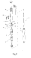
- FIG. 2 is an exploded view of FIG. 1;
- FIG. 3 is a cross sectional view taken along a longitudinal line of the pen light thereof;
- FIG. 4 is a perspective view showing a cap is attached to a tail of a barrel of the pen light
- FIG. 5 is a perspective view of the cap
- FIG. 6 is a cross sectional view of a conventional pen light.
- a pen light in accordance with the present invention generally includes a barrel 1 and a cap 2 capable of attaching to the barrel 1 .
- the barrel 1 is provided with a cartridge 3 for writing.
- the barrel 1 is made from transparent material, such as the transparent plastic material.
- the barrel 1 is provided with connecting portions 11 , 12 at both ends thereof for engagement with the cap 2 .
- a lighting assembly 4 is arranged within the cap 2 and includes a lighting device 41 and which is powered by a battery 43 disposed within the cap 2 .
- a switch 42 is arranged on the cap 2 for controlling On/Off of the lighting device 41 .
- the lighting device 41 is arranged to an end 21 of the cap 2 and which is adjacent to the barrel 1 .
- the cap 2 is further provided with a convex lens 22 adjacent to the lighting device 41 .
- the lighting assembly 4 includes a printed circuit board 44 on which an LED 41 is mounted.
- the switch 42 is electrically connected on the printed circuit board 44 for controlling the On/Off of the LED 41 .
- the printed circuit board 44 is provided with first and second switching junctions 441 , 442 at one side, while another side of the printed circuit board 44 is provided with a standard circuitry and a test circuitry.
- the standard and test circuitry are integrated in an IC chip 443 .
- a pushing button 444 is arranged to the switching junctions 441 , 442 for selectively triggering the first or second switching junctions 441 , 442 .
- the cap 2 can be completely separated from the barrel 1 and the lighting assembly 4 is arranged within the cap 2 , the cap 2 can be used individually as a flashlight, such as shown in FIG. 4 .
- the light beam from the lighting device 41 is projected to the end 21 which is in engagement with the barrel 1 .
- the barrel 1 is made from transparent plastic material, no matter the cap 2 is attached to a front end 11 or rear end 12 of the barrel 1 , as long as the lighting device 41 of the lighting assembly 4 is switched on, the barrel 1 can be spectacularly shined through thereby providing aesthetic appearance.
- the lighting assembly 4 is provided with a test circuitry
- the lighting device 41 can be used as a temporary light, i.e. the lighting device 41 will be kept on as long as the pushing button 444 is depressed, while the lighting device 41 will go off once the pushing button 444 is released.
- This is specially suitable for testing the function and aesthetic appearance of the pen light.
- the standard circuit can be triggered on firstly. Then the customer can easily test the effect by pressing down the pushing button to check the effect. Accordingly, the customer can be readily attracted and thereby increasing the sales volume.
- the convex lens 22 adjacent to the lighting device 41 is replaced by a concave lens.
Abstract
A pen light includes a barrel and a cap attached to the barrel, and cartridge being arranged within the barrel. The barrel is made from transparent material and is provided with connecting portions at both ends thereof for engagement with the cap. A lighting assembly is arranged in the cap and includes a lighting device being arranged within the cap and which is powered by a battery disposed within the cap. A switch is arranged on the cap for controlling On/Off of the lighting device, wherein the lighting device is arranged to an end of the cap. The cap can be used individually as a flashlight or together with the barrel thereby providing aesthetic appearance of the barrel.
Description
The present invention relates to a flashlight, and more particularly to a pen light in which a light device is incorporated in a cap thereof. The cap can be used individually as a flashlight. In addition, when the light device is lit, the barrel reflects the light such that the light beam can be directed to the intended direction no matter the cap is disposed on tip or tail.
As shown in FIG. 6, a conventional pen light generally includes a cartridge (b) disposed in. a barrel (a). A lighting device (c) is arranged in adjacent to the cartridge (b). The On/Off of the lighting device (c) as well as the extension/withdrawal of a tip of the cartridge (b) are both controlled by a push-button device (d) located in a rear end of the barrel (a). In an alternative, the barrel (a) is provided with a helical retracting device to withdraw the tip of the cartridge (b) into the barrel (a).
The conventional pen light can be concluded with the following defects.
1. The push-button has a complicated configuration which no doubt increases the manufacturing cost. Moreover, it takes time to assemble them.
2. It does not include a cap. As a result, it needs an additional retracting mechanism to withdraw the tip of the cartridge into the barrel. Again, the retracting mechanism increases the cost.
3. The retracting mechanism has a comparable complicated configuration. It generally has an outer diameter of 7 mm. When the thickness of the barrel is taken into account, the overall outer diameter will reach 13 mm. This is too large for a comfortable grip.
4. For those pens without retracting mechanism, a cap can be purchased to protect the tip of the cartridge. However, once the tip of the cartridge is closed by the cap, the intended purpose of the pen light is impaired. In addition, it would be difficult to perceive that On/Off of the pen light when the tip of the cartridge is enclosed. This leads unwanted exhaustion of a battery used to power the light device.
5. The conventional pen light has only one intended usage.
6. The energy loss is too high as the light path from the lighting device to an end is too long. As a result, a performance thereof is impaired.
7. The conventional pen light does not include a test switch which the customer can test the pen light. As a result, it would be unlikely that the customer can be attracted by the inherited functions of the pen light.
It is an objective of this invention to provide a pen light in which a lighting device is disposed in a cap thereof. The cap can be used individually or together with a barrel of a pen to serve as a lighting instrument.
It is still an objective of this invention to provide a pen light in which the barrel has a comparable small outer diameter thereby providing a user-friendly usage.
In order to achieve the objectives set forth, a pen light in accordance with the present invention includes a barrel and a cap attached to the barrel, and cartridge being arranged within the barrel. The barrel is made from transparent material and is provided with connecting portions at both ends thereof for engagement with the cap. A lighting assembly is arranged in the cap and includes a lighting device being arranged within the cap and which is powered by a battery disposed within the cap. A switch is arranged on the cap for controlling On/Off of the lighting device, wherein the lighting device is arranged to an end of the cap. The cap can be used individually as a flashlight or together with the barrel thereby providing gorgeous appearance of the barrel. A lens is arranged adjacent to the lighting device to increase the aesthetic appearance.
According to one aspect of the present invention, wherein the lighting means includes a printed circuit board on which an LED is mounted. The switch is electrically mounted on the printed circuit board for controlling the LED. The printed circuit board is provided with first and second switching junctions at one side, while another side of the printed circuit board is provided with a standard circuitry and a test circuitry. A pushing button is arranged to the switching junctions for selectively triggering the first or second switching junctions.
Other objects and advantages of the present invention will become apparent from the following detailed description of the preferred embodiments thereof taken in conjunction with the accompanying drawings wherein:
FIG. 1 is an assembled view of a pen light in accordance with the present invention;
FIG. 2 is an exploded view of FIG. 1;
FIG. 3 is a cross sectional view taken along a longitudinal line of the pen light thereof;
FIG. 4 is a perspective view showing a cap is attached to a tail of a barrel of the pen light;
FIG. 5 is a perspective view of the cap; and
FIG. 6 is a cross sectional view of a conventional pen light.
Referring to FIGS. 1 and 2, a pen light in accordance with the present invention generally includes a barrel 1 and a cap 2 capable of attaching to the barrel 1. The barrel 1 is provided with a cartridge 3 for writing.
The barrel 1 is made from transparent material, such as the transparent plastic material. The barrel 1 is provided with connecting portions 11, 12 at both ends thereof for engagement with the cap 2.
A lighting assembly 4 is arranged within the cap 2 and includes a lighting device 41 and which is powered by a battery 43 disposed within the cap 2. A switch 42 is arranged on the cap 2 for controlling On/Off of the lighting device 41. The lighting device 41 is arranged to an end 21 of the cap2 and which is adjacent to the barrel 1. The cap 2 is further provided with a convex lens 22 adjacent to the lighting device 41. By this arrangement, a light beam from the lighting device 41 will effectively shine through an inner wall of the barrel 1, thereby increasing an aesthetic effect of the barrel 1.
Referring to FIG. 3, the lighting assembly 4 includes a printed circuit board 44 on which an LED 41 is mounted. The switch 42 is electrically connected on the printed circuit board 44 for controlling the On/Off of the LED 41. The printed circuit board 44 is provided with first and second switching junctions 441, 442 at one side, while another side of the printed circuit board 44 is provided with a standard circuitry and a test circuitry. In the preferred embodiment, the standard and test circuitry are integrated in an IC chip 443. A pushing button 444 is arranged to the switching junctions 441, 442 for selectively triggering the first or second switching junctions 441, 442.
According to the present invention, since the cap 2 can be completely separated from the barrel 1 and the lighting assembly 4 is arranged within the cap 2, the cap 2 can be used individually as a flashlight, such as shown in FIG. 4. In addition, the light beam from the lighting device 41 is projected to the end 21 which is in engagement with the barrel 1. As the barrel 1 is made from transparent plastic material, no matter the cap 2 is attached to a front end 11 or rear end 12 of the barrel 1, as long as the lighting device 41 of the lighting assembly 4 is switched on, the barrel 1 can be splendidly shined through thereby providing aesthetic appearance.
In addition, the lighting assembly 4 is provided with a test circuitry, the lighting device 41 can be used as a temporary light, i.e. the lighting device 41 will be kept on as long as the pushing button 444 is depressed, while the lighting device 41 will go off once the pushing button 444 is released. This is specially suitable for testing the function and aesthetic appearance of the pen light. Specially, when the pen light is put on the shelf and completely covered by a transparent film, the standard circuit can be triggered on firstly. Then the customer can easily test the effect by pressing down the pushing button to check the effect. Accordingly, the customer can be readily attracted and thereby increasing the sales volume.
In another embodiment of the invention, the convex lens 22 adjacent to the lighting device 41, as shown in FIGS. 2 and 4, is replaced by a concave lens.
While specific illustrated embodiment has been shown and described, it will be appreciated by those skilled in the-art that various modifications, changes, and additions can be made to the invention without departing from the spirit and scope thereof as set forth in the following claims.
Claims (6)
1. A pen light including a barrel and a cap attached to said barrel, a cartridge being arranged within said barrel, characterized in that said barrel is made from transparent material, said barrel being provided with connecting portions at both ends thereof for engagement with said cap, lighting means arranged in said cap including a lighting device being arranged within said cap and which is powered by a battery disposed within said cap, a switch arranged on said cap for controlling on/off operation of said lighting device in one of a standard mode and a test mode, wherein said lighting device is arranged to an end of said cap.
2. A pen light as recited in claim 1 , wherein said lighting means includes a printed circuit board on which an LED is mounted, said switch being electrically mounted on said printed circuit board for controlling said LED, said printed circuit board being provided with first and second switching junctions on one side, the other side of said printed circuit board being provided with standard circuitry configured to cause said LED to operate in said standard mode and test circuitry configured to cause said LED to operate in said test mode, a push button being arranged to said switching junctions for selectively triggering one of said first and second switching junctions, said first switching junction being configured to activate said standard circuitry when triggered and said second switching junction being configured to activate said test circuitry when triggered.
3. A pen light as recited in claim 2 , wherein a concave lens is arranged adjacent to said lighting device.
4. A pen light as recited in claim 1 , wherein said standard mode is one in which said lighting device is alternatively turned on and off by activation of said switch, and said test mode is one in which said lighting device remains turned on only as long as said switch is activated.
5. A pen light including a barrel and a cap attached to said barrel, a cartridge being arranged within said barrel, characterized in that said barrel is made from transparent material, said barrel being provided with connecting portions at both ends thereof for engagement with said cap, lighting means arranged in said cap including a lighting device being arranged within said cap and which is powered by a battery disposed within said cap, a switch arranged on said cap for controlling on/off operation of said lighting device, wherein said lighting device is arranged to an end of said cap, and wherein a convex lens is adjacent to said lighting device.
6. A pen light as recited in claim 2 , wherein said standard circuitry and said test circuitry are included in an integrated circuit.
Priority Applications (2)
| Application Number | Priority Date | Filing Date | Title |
|---|---|---|---|
| DE20018801U DE20018801U1 (en) | 2000-11-03 | 2000-11-03 | Illuminated pen |
| US09/709,496 US6439734B1 (en) | 2000-11-03 | 2000-11-13 | Pen light |
Applications Claiming Priority (2)
| Application Number | Priority Date | Filing Date | Title |
|---|---|---|---|
| DE20018801U DE20018801U1 (en) | 2000-11-03 | 2000-11-03 | Illuminated pen |
| US09/709,496 US6439734B1 (en) | 2000-11-03 | 2000-11-13 | Pen light |
Publications (1)
| Publication Number | Publication Date |
|---|---|
| US6439734B1 true US6439734B1 (en) | 2002-08-27 |
Family
ID=26056608
Family Applications (1)
| Application Number | Title | Priority Date | Filing Date |
|---|---|---|---|
| US09/709,496 Expired - Fee Related US6439734B1 (en) | 2000-11-03 | 2000-11-13 | Pen light |
Country Status (2)
| Country | Link |
|---|---|
| US (1) | US6439734B1 (en) |
| DE (1) | DE20018801U1 (en) |
Cited By (13)
| Publication number | Priority date | Publication date | Assignee | Title |
|---|---|---|---|---|
| US20030112623A1 (en) * | 2001-12-14 | 2003-06-19 | Zen Design Group, Ltd. | Ultraviolet light writing system |
| US6672972B1 (en) * | 2002-01-14 | 2004-01-06 | Robert Allen Stone | Instructional device for improving golf skills |
| US6682212B2 (en) * | 2001-03-30 | 2004-01-27 | Sheng-Siong Gao | Light-emitting pen with a light-emitting body at a middle section of a pen tube |
| US6773192B1 (en) * | 2003-11-19 | 2004-08-10 | Prosonic Technology Corp. | Light-emitting USB mobile disk-pen |
| US20050251152A1 (en) * | 2004-05-05 | 2005-11-10 | Atrium Medical Corp. | Illuminated medicated ink marker |
| US20050271452A1 (en) * | 2001-12-14 | 2005-12-08 | Sun Yu | Ultraviolet invisible ink dry erase board |
| US7204590B1 (en) | 2003-10-10 | 2007-04-17 | Andrew Lenoir | System and method for inducing and measuring a consensual pupillary response |
| US20100098478A1 (en) * | 2008-10-22 | 2010-04-22 | Beifa Group Co., Ltd. | Retractable lamp pen |
| US20100104350A1 (en) * | 2007-04-13 | 2010-04-29 | Jixian Hu | Led luminous pen |
| US20110090702A1 (en) * | 2009-10-20 | 2011-04-21 | Hon Hai Precision Industry Co., Ltd. | Light pen |
| US9072541B2 (en) | 2013-10-24 | 2015-07-07 | Steven M. Hacker | Surgical scalpel handle with illuminator |
| US9108454B1 (en) * | 2008-06-10 | 2015-08-18 | Samuel Rosenberg | Defensive writing instrument |
| EP3098087A1 (en) | 2015-05-27 | 2016-11-30 | Vivapen d.o.o. | Lighting pen |
Families Citing this family (1)
| Publication number | Priority date | Publication date | Assignee | Title |
|---|---|---|---|---|
| DE102011017407A1 (en) * | 2011-04-18 | 2012-10-18 | Eberhard Koch | Fluorescent pen, has LED provided at interior portion of pen housing over concave prism, light conductor placed at underside of LED, and power supply provided inside pen housing, where upper part of prism comprises bulged portion |
Citations (2)
| Publication number | Priority date | Publication date | Assignee | Title |
|---|---|---|---|---|
| US2979602A (en) * | 1957-12-26 | 1961-04-11 | Harry E Barnett | Combination illuminated writing instrument and flashlight |
| US6099185A (en) * | 1999-08-09 | 2000-08-08 | Excellence Optoelectronics Inc. | Light pen with multicolor light sources |
-
2000
- 2000-11-03 DE DE20018801U patent/DE20018801U1/en not_active Expired - Lifetime
- 2000-11-13 US US09/709,496 patent/US6439734B1/en not_active Expired - Fee Related
Patent Citations (2)
| Publication number | Priority date | Publication date | Assignee | Title |
|---|---|---|---|---|
| US2979602A (en) * | 1957-12-26 | 1961-04-11 | Harry E Barnett | Combination illuminated writing instrument and flashlight |
| US6099185A (en) * | 1999-08-09 | 2000-08-08 | Excellence Optoelectronics Inc. | Light pen with multicolor light sources |
Cited By (19)
| Publication number | Priority date | Publication date | Assignee | Title |
|---|---|---|---|---|
| US6682212B2 (en) * | 2001-03-30 | 2004-01-27 | Sheng-Siong Gao | Light-emitting pen with a light-emitting body at a middle section of a pen tube |
| US20050271452A1 (en) * | 2001-12-14 | 2005-12-08 | Sun Yu | Ultraviolet invisible ink dry erase board |
| US20030112623A1 (en) * | 2001-12-14 | 2003-06-19 | Zen Design Group, Ltd. | Ultraviolet light writing system |
| US20050036303A1 (en) * | 2001-12-14 | 2005-02-17 | Sun Yu | Ultraviolet light writing system |
| US6860616B2 (en) * | 2001-12-14 | 2005-03-01 | Iq Hong Kong, Ltd. | Ultraviolet light writing system |
| US6672972B1 (en) * | 2002-01-14 | 2004-01-06 | Robert Allen Stone | Instructional device for improving golf skills |
| US7204590B1 (en) | 2003-10-10 | 2007-04-17 | Andrew Lenoir | System and method for inducing and measuring a consensual pupillary response |
| US7452079B1 (en) | 2003-10-10 | 2008-11-18 | Andrew Lenoir | System and method for inducing and measuring a consensual pupillary response |
| US6773192B1 (en) * | 2003-11-19 | 2004-08-10 | Prosonic Technology Corp. | Light-emitting USB mobile disk-pen |
| US20050251152A1 (en) * | 2004-05-05 | 2005-11-10 | Atrium Medical Corp. | Illuminated medicated ink marker |
| US20100104350A1 (en) * | 2007-04-13 | 2010-04-29 | Jixian Hu | Led luminous pen |
| US9108454B1 (en) * | 2008-06-10 | 2015-08-18 | Samuel Rosenberg | Defensive writing instrument |
| US9428002B2 (en) | 2008-06-10 | 2016-08-30 | Samuel Rosenberg | Defensive writing instrument |
| US20100098478A1 (en) * | 2008-10-22 | 2010-04-22 | Beifa Group Co., Ltd. | Retractable lamp pen |
| US8182167B2 (en) * | 2008-10-22 | 2012-05-22 | Beifa Group Co., Ltd. | Retractable lamp pen |
| US8632270B2 (en) | 2008-10-22 | 2014-01-21 | Beifa Group Co., Ltd. | Retractable lamp pen |
| US20110090702A1 (en) * | 2009-10-20 | 2011-04-21 | Hon Hai Precision Industry Co., Ltd. | Light pen |
| US9072541B2 (en) | 2013-10-24 | 2015-07-07 | Steven M. Hacker | Surgical scalpel handle with illuminator |
| EP3098087A1 (en) | 2015-05-27 | 2016-11-30 | Vivapen d.o.o. | Lighting pen |
Also Published As
| Publication number | Publication date |
|---|---|
| DE20018801U1 (en) | 2001-01-04 |
Similar Documents
| Publication | Publication Date | Title |
|---|---|---|
| US6439734B1 (en) | Pen light | |
| US5463539A (en) | Miniature pocket flashlight with lens module and outer flexible sheath | |
| US7140748B2 (en) | LED flashlight | |
| US6830403B2 (en) | Light-emitting pen with a light reflecting chamber | |
| US6299372B1 (en) | Advertise effect photo pen | |
| US5803583A (en) | Pen with light-emitting means | |
| US6513947B1 (en) | Flashlight having a water-resistant switch | |
| KR0118606Y1 (en) | Radiation | |
| EP1973750B1 (en) | Pen-and-electronic device assembly | |
| US10775001B1 (en) | Compact flashlight | |
| US7442890B1 (en) | Button device | |
| US7758267B1 (en) | Cosmetic container with light | |
| JP2004361955A (en) | Battery actuation type bar-shaped lamp | |
| WO2006081729A1 (en) | A light emitting pen with led | |
| US6777890B1 (en) | Cylindrical miniature-LED light-emitting device | |
| US7121752B2 (en) | Multi-purpose pen | |
| US5971750A (en) | Lighter having the function of indicating | |
| KR200306928Y1 (en) | Luminous Sharp-Pencil | |
| CA2455767C (en) | Light-emitting pen with a light reflecting chamber | |
| US6994446B2 (en) | Light emitting rotary double refill pen | |
| US20040062036A1 (en) | Light pen with the functions of illumination and logo indication | |
| KR200245851Y1 (en) | Lighter combined use flash light | |
| US20050083680A1 (en) | Illuminable writing instrument | |
| JP3143982U (en) | Lighting equipment for writing instruments | |
| KR200342301Y1 (en) | Ballpoint pen having a button with a lighting device |
Legal Events
| Date | Code | Title | Description |
|---|---|---|---|
| REMI | Maintenance fee reminder mailed | ||
| LAPS | Lapse for failure to pay maintenance fees | ||
| STCH | Information on status: patent discontinuation |
Free format text: PATENT EXPIRED DUE TO NONPAYMENT OF MAINTENANCE FEES UNDER 37 CFR 1.362 |
|
| FP | Lapsed due to failure to pay maintenance fee |
Effective date: 20060827 |