US6445560B1 - Gas-filled surge protector with external short-circuiting device - Google Patents
Gas-filled surge protector with external short-circuiting device Download PDFInfo
- Publication number
- US6445560B1 US6445560B1 US09/367,948 US36794800A US6445560B1 US 6445560 B1 US6445560 B1 US 6445560B1 US 36794800 A US36794800 A US 36794800A US 6445560 B1 US6445560 B1 US 6445560B1
- Authority
- US
- United States
- Prior art keywords
- short
- spacer
- electrodes
- insulator
- circuiting link
- Prior art date
- Legal status (The legal status is an assumption and is not a legal conclusion. Google has not performed a legal analysis and makes no representation as to the accuracy of the status listed.)
- Expired - Lifetime
Links
Images
Classifications
-
- H—ELECTRICITY
- H01—ELECTRIC ELEMENTS
- H01T—SPARK GAPS; OVERVOLTAGE ARRESTERS USING SPARK GAPS; SPARKING PLUGS; CORONA DEVICES; GENERATING IONS TO BE INTRODUCED INTO NON-ENCLOSED GASES
- H01T1/00—Details of spark gaps
- H01T1/14—Means structurally associated with spark gap for protecting it against overload or for disconnecting it in case of failure
Definitions
- the present invention relates to electrical components, and is to be applied in the structural design of a gas-filled surge arrester that is provided with an external short-circuit device.
- Short-circuit device provided with external short-circuit devices are common both in two-electrode and in three-electrode surge arresters. They function to protect the surge arrester in long-term load situations.
- a short-circuit device contains a structural element that can melt at higher temperatures, with the aid of which the two electrodes, or the center electrode and one or both end electrodes, are short-circuited.
- a spring contact and an arrester contact are arranged electrically parallel to the two electrodes, the spring contact being held at a distance from the arrester contact by a spacer that is adjacent to the insulator of the arrester and that softens at increased temperatures.
- This spacer is made of a glass-fiber-reinforced plastic that is dimensionally stable at normal operating temperature and that softens at increased temperatures, e.g. polycarbonate.
- a conventional external short-circuit device for two- and three-electrode surge arresters is described in WO 87/06399.
- This short-circuit device is composed of a two-layer clamp made of a thermostatic bimetal, the two layers of the clamp passing, over at their free ends, into a monostable snap element. In the event of an overload, one part of the snap element functions to bridge the two external electrodes of the arrester. In two-electrode arresters, the bimetal clamp sits on the insulator of the arrester.
- a conventional three-electrode arrester an external short-circuit device is described that is composed of a bracket, made of an open ring, that is placed on the center electrode, the one end of the ring forming, together with arms shaped at the sides, a short-circuiting link.
- the free ends of the two arms are held at a radial distance from the end electrodes of the arrester by means of a spacer that is made of a meltable insulating material and that is arranged between the center electrode and the short-circuiting link.
- the free ends of the two arms can thereby be provided with special contacts.
- French Patent No. 2 670 624 describes a similarly configured external short-circuit device that can be used both for three-electrode and for two-electrode arresters. In this device, the free ends of the two arms of the short-circuiting link are bent in such a way that they abut the circumferential edge of the respective electrode, the free ends having in the area of the point of contact an insulating coating that can melt when heat is applied.
- the object of the present invention is to configure the short-circuit device in such a way that it extends radially past the surge arrester as little as possible, ensures a safe contacting, and is easy to install.
- the spacer is arranged between the center part of the short-circuiting link and the insulator.
- Such a configuration of the short-circuit device makes use of the conventional design of a short-circuit device such as that described in U.S. Pat. No. 4,984,125, but the bracket, in this context, is placed not on an electrode, but rather—in a manner such as described in French Patent No. 2 670 624)—on the insulator located between two electrodes.
- the short-circuiting link is arranged without potential.
- this can prove to be advantageous insofar as no disturbing short circuit can occur in case of contact of one side of the short-circuiting link with a contact terminal that conducts potential.
- the spacer Since the spacer is arranged between the short-circuiting link and the insulator, the spacer can be of relatively thin construction; in addition, a relatively inexpensive thermoplastic plastic material can be used for the spacer, since the insulator heats up with a delay relative to the electrodes that are to be short-circuited.
- a surge arrester having short-circuit device configured according to the present invention is thus distinguished by a design that is very compact and that saves a great deal of space with regard to the insertion of a larger number of such arresters into cartridges, the short-circuit device being able to be made of one or two parts and to be easily adapted to various arrester geometries due to its simple configuration.
- the short-circuit device can also be retrofitted; it can also be exchanged after being blown, as long as the actual arrester is still intact.
- the short-circuit device configured according to the present invention can be used both for two-electrode and for three-electrode arresters.
- each of the two insulators present in such arresters is to be equipped with a short-circuit device of the present configuration.
- the open snap-on ring of the new short-circuit device can be made of a heat-resistant plastic or of a resilient (spring-like) metal that conducts less well electrically (e.g. spring steel or a copper alloy), a metallic short-circuiting link that conducts very well electrically (e.g. made of copper) being placed onto the one end of the open ring or being fastened there in some other way.
- the open ring is made of the same material as the actual short-circuiting link, and is configured in one piece with the latter, the open ring being provided at the one end with two side bars, shaped at the sides, for the formation of the short-circuiting link. In order to improve the contacting, these side bars can be bent slightly at their free ends.
- a plastic part that can be melted may be used as a spacer for the short-circuit device.
- a spacer made of a soldering material can also be used.
- These spacers can, for example, have the form of a rivet fastened to the center part of the link.
- a plastic clip placed on the center part of the link can also be used.
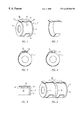
- FIG. 1 shows a gas-filled surge arrester having two electrodes, equipped with a short-circuit device according to the present invention.
- FIG. 2 shows the short-circuit device without arrester.
- FIG. 3 shows a surge arrester in which the spacer of the short-circuit device is a rivet.
- FIG. 4 shows a surge arrester having a short-circuit device in which the spacer is a plastic clip.
- FIG. 5 shows a short-circuit device having a special configuration of the electrodes of the arrester.
- FIG. 6 shows a three-electrode arrester having two short-circuit devices placed on the two insulators.
- FIG. 1 shows a surge arrester 1 including an insulator 2 and two end electrodes 3 and 4 .
- a short-circuit device 10 is placed on insulator 2 , the device including an open ring 11 (shown separately in FIG. 2) made of cold-hammered metal and an insulating spacer 20 .
- Open ring 11 is fashioned, in this context, as a short-circuiting link 12 at its one end, and has a center part that runs in planar fashion and two side bars 14 and 15 that are shaped at the sides and that are bent slightly at the ends.
- the axial length of short-circuiting link 12 is thus chosen such that the short-circuiting link does not extend past the surge arrester axially (see also FIG. 5 ).
- Spacer 20 can also be made of a soldering material.
- the short-circuit device for arrester 1 is likewise composed of an open ring that can be snapped onto the insulator of the arrester, a plastic rivet 21 being provided as a spacer for actual short-circuiting link 13 , the rivet being fixed in a bored hole of center part 13 of the short-circuiting link.
- a plastic clip 22 that is pushed onto center part 13 of the short-circuiting link can be used as a spacer.
- electrodes 31 and 32 of the surge arrester are provided with a larger outer diameter than insulator 2 . The bending of the ends of actual short-circuit device 16 at the ends thus becomes unnecessary.
- FIG. 6 shows an arrester in which another center electrode 5 is arranged between end electrodes 3 and 4 , the arrester being composed of two insulators 6 and 7 .
- a short-circuit device 10 is placed onto each insulator.
Abstract
Description
Claims (4)
Applications Claiming Priority (3)
| Application Number | Priority Date | Filing Date | Title |
|---|---|---|---|
| DE19708651A DE19708651A1 (en) | 1997-02-21 | 1997-02-21 | Gas-filled surge arrester with external short-circuit device |
| DE19708651 | 1997-02-21 | ||
| PCT/DE1998/000565 WO1998037605A1 (en) | 1997-02-21 | 1998-02-20 | Gas-filled surge protector with external short-circuiting device |
Publications (1)
| Publication Number | Publication Date |
|---|---|
| US6445560B1 true US6445560B1 (en) | 2002-09-03 |
Family
ID=7822117
Family Applications (1)
| Application Number | Title | Priority Date | Filing Date |
|---|---|---|---|
| US09/367,948 Expired - Lifetime US6445560B1 (en) | 1997-02-21 | 1998-02-20 | Gas-filled surge protector with external short-circuiting device |
Country Status (7)
| Country | Link |
|---|---|
| US (1) | US6445560B1 (en) |
| EP (2) | EP1821379B1 (en) |
| JP (1) | JP4290224B2 (en) |
| KR (1) | KR20000075515A (en) |
| CN (3) | CN1282288C (en) |
| DE (2) | DE19708651A1 (en) |
| WO (1) | WO1998037605A1 (en) |
Cited By (12)
| Publication number | Priority date | Publication date | Assignee | Title |
|---|---|---|---|---|
| US20040094330A1 (en) * | 2000-11-30 | 2004-05-20 | Jurgen Boy | Electrical component, arrangement for said component and method for producing said arrangement |
| US20080204963A1 (en) * | 2007-02-28 | 2008-08-28 | Baker Scott K | Overvoltage protection plug |
| US20080225458A1 (en) * | 2005-04-12 | 2008-09-18 | Jurgen Boy | Surge Protector |
| US20090128978A1 (en) * | 2007-11-16 | 2009-05-21 | Chanh Cuong Vo | Hybrid surge protector for a network interface device |
| US20090269954A1 (en) * | 2008-04-25 | 2009-10-29 | Vern Loch | Circuit protection block |
| US20090296303A1 (en) * | 2008-05-27 | 2009-12-03 | Petersen Cyle D | Overvoltage Protection Plug |
| US20100231346A1 (en) * | 2009-03-13 | 2010-09-16 | Shinko Electric Industries Co., Ltd. | 3-electrode surge protective device |
| US20110013334A1 (en) * | 2008-01-31 | 2011-01-20 | Peter Bobert | Electrical Protection Component with a Short-Circuiting Device |
| US20110013335A1 (en) * | 2008-01-31 | 2011-01-20 | Peter Bobert | Electrical Protection Component with a Short-Circuiting Device |
| US8547678B2 (en) | 2008-12-16 | 2013-10-01 | Epcos Ag | Surge arrester having a short-circuit device |
| US10148085B2 (en) * | 2014-03-13 | 2018-12-04 | Epcos Ag | Surge arrester having protection against heating |
| US11128107B2 (en) * | 2015-12-09 | 2021-09-21 | Epcos Ag | Electrical protection component having a thermal short-circuit device |
Families Citing this family (5)
| Publication number | Priority date | Publication date | Assignee | Title |
|---|---|---|---|---|
| SE9804538D0 (en) | 1998-12-23 | 1998-12-23 | Jensen Elektronik Ab | Gas discharge tube |
| DE19907319B4 (en) * | 1999-02-20 | 2005-04-28 | Krone Gmbh | Snubber |
| TW522420B (en) * | 2000-06-20 | 2003-03-01 | Takashi Katoda | Fabrication method of surge protector device and the device fabricated by the method |
| DE102008035903A1 (en) | 2008-07-31 | 2010-02-18 | Epcos Ag | Electrical gas filled overvoltage arrester, has short circuit device arranged at distance from electrodes using coatings applied on short circuit device such that electrodes are electrically insulated from each other |
| DE102010036909B3 (en) * | 2010-08-06 | 2012-02-16 | Phoenix Contact Gmbh & Co. Kg | Thermal overload protection device |
Citations (16)
| Publication number | Priority date | Publication date | Assignee | Title |
|---|---|---|---|---|
| US4062054A (en) * | 1976-08-31 | 1977-12-06 | Tii Corporation | Multi-function fail-safe arrangements for overvoltage gas tubes |
| US4150414A (en) * | 1977-11-14 | 1979-04-17 | Tii Corporation | Air gap short circuiting device for gas tube arrester |
| US4303959A (en) * | 1977-10-18 | 1981-12-01 | Tii Industries, Inc. | Fail safe surge arrester systems |
| US4320435A (en) * | 1979-03-06 | 1982-03-16 | Tii Industries, Inc. | Surge arrester assembly |
| WO1987006399A1 (en) | 1986-04-09 | 1987-10-22 | Schaltbau Gesellschaft Mbh | Device for protecting a surge arrester against overheating |
| EP0312729A1 (en) | 1987-10-20 | 1989-04-26 | KRONE Aktiengesellschaft | Heat-sensitive protection device for a surge arrester incorporated in surge protector assemblies for telephone lines |
| US4910489A (en) * | 1989-05-01 | 1990-03-20 | Porta Systems Corp. | Gas tube fail-safe device for telephone protector modules |
| US4912592A (en) * | 1987-05-01 | 1990-03-27 | Cooper (Uk) Limited | Gas-filled surge arrestor |
| US4984125A (en) * | 1988-08-10 | 1991-01-08 | Sankosha Corporation | Arrester apparatus |
| US5029302A (en) * | 1990-08-29 | 1991-07-02 | Illinois Tool Works | Fail safe gas tube |
| FR2670624A1 (en) | 1990-12-14 | 1992-06-19 | Pensar Ind | Short-circuit and casing for lightning arrester |
| EP0516922A2 (en) | 1991-06-05 | 1992-12-09 | KRONE Aktiengesellschaft | Thermic overload protection device for electronic components |
| EP0548587A1 (en) | 1991-12-24 | 1993-06-30 | Cerberus Ag | Overvoltage protection device |
| US5475356A (en) * | 1993-06-03 | 1995-12-12 | Shinko Electric Industries Co., Ltd. | Gas-tube arrester |
| US5633777A (en) * | 1994-10-13 | 1997-05-27 | Siemens Aktiengesellschaft | Gas-filled, three-electrode overvoltage surge arrester for large switching capacities |
| US5644465A (en) * | 1993-03-17 | 1997-07-01 | Siemens Aktiengesellschaft | Surge arrester with external short-circuit device |
Family Cites Families (2)
| Publication number | Priority date | Publication date | Assignee | Title |
|---|---|---|---|---|
| JPH06251852A (en) * | 1993-02-26 | 1994-09-09 | Shinko Electric Ind Co Ltd | Lightning arresting tube |
| JPH06290852A (en) * | 1993-03-31 | 1994-10-18 | Shinko Electric Ind Co Ltd | Aerrester with fail-safe mechanism |
-
1997
- 1997-02-21 DE DE19708651A patent/DE19708651A1/en not_active Ceased
-
1998
- 1998-02-20 DE DE59814060T patent/DE59814060D1/en not_active Expired - Lifetime
- 1998-02-20 CN CNB991183142A patent/CN1282288C/en not_active Expired - Lifetime
- 1998-02-20 JP JP53616698A patent/JP4290224B2/en not_active Expired - Lifetime
- 1998-02-20 WO PCT/DE1998/000565 patent/WO1998037605A1/en active IP Right Grant
- 1998-02-20 CN CNB988021196A patent/CN1282286C/en not_active Expired - Lifetime
- 1998-02-20 US US09/367,948 patent/US6445560B1/en not_active Expired - Lifetime
- 1998-02-20 EP EP07009636.7A patent/EP1821379B1/en not_active Expired - Lifetime
- 1998-02-20 EP EP98916804A patent/EP0962037B1/en not_active Expired - Lifetime
- 1998-02-20 KR KR1019997007574A patent/KR20000075515A/en not_active Application Discontinuation
-
1999
- 1999-08-27 CN CN99118313A patent/CN1082734C/en not_active Expired - Lifetime
Patent Citations (17)
| Publication number | Priority date | Publication date | Assignee | Title |
|---|---|---|---|---|
| US4062054A (en) * | 1976-08-31 | 1977-12-06 | Tii Corporation | Multi-function fail-safe arrangements for overvoltage gas tubes |
| US4303959A (en) * | 1977-10-18 | 1981-12-01 | Tii Industries, Inc. | Fail safe surge arrester systems |
| US4150414A (en) * | 1977-11-14 | 1979-04-17 | Tii Corporation | Air gap short circuiting device for gas tube arrester |
| US4320435A (en) * | 1979-03-06 | 1982-03-16 | Tii Industries, Inc. | Surge arrester assembly |
| WO1987006399A1 (en) | 1986-04-09 | 1987-10-22 | Schaltbau Gesellschaft Mbh | Device for protecting a surge arrester against overheating |
| US4912592A (en) * | 1987-05-01 | 1990-03-27 | Cooper (Uk) Limited | Gas-filled surge arrestor |
| EP0312729A1 (en) | 1987-10-20 | 1989-04-26 | KRONE Aktiengesellschaft | Heat-sensitive protection device for a surge arrester incorporated in surge protector assemblies for telephone lines |
| US4984125A (en) * | 1988-08-10 | 1991-01-08 | Sankosha Corporation | Arrester apparatus |
| US4910489A (en) * | 1989-05-01 | 1990-03-20 | Porta Systems Corp. | Gas tube fail-safe device for telephone protector modules |
| US5029302A (en) * | 1990-08-29 | 1991-07-02 | Illinois Tool Works | Fail safe gas tube |
| FR2670624A1 (en) | 1990-12-14 | 1992-06-19 | Pensar Ind | Short-circuit and casing for lightning arrester |
| EP0516922A2 (en) | 1991-06-05 | 1992-12-09 | KRONE Aktiengesellschaft | Thermic overload protection device for electronic components |
| US5248953A (en) * | 1991-06-05 | 1993-09-28 | Krone Aktiengesellschaft | Thermal overload protection device for electronic components |
| EP0548587A1 (en) | 1991-12-24 | 1993-06-30 | Cerberus Ag | Overvoltage protection device |
| US5644465A (en) * | 1993-03-17 | 1997-07-01 | Siemens Aktiengesellschaft | Surge arrester with external short-circuit device |
| US5475356A (en) * | 1993-06-03 | 1995-12-12 | Shinko Electric Industries Co., Ltd. | Gas-tube arrester |
| US5633777A (en) * | 1994-10-13 | 1997-05-27 | Siemens Aktiengesellschaft | Gas-filled, three-electrode overvoltage surge arrester for large switching capacities |
Cited By (22)
| Publication number | Priority date | Publication date | Assignee | Title |
|---|---|---|---|---|
| US20040094330A1 (en) * | 2000-11-30 | 2004-05-20 | Jurgen Boy | Electrical component, arrangement for said component and method for producing said arrangement |
| US7612294B2 (en) * | 2000-11-30 | 2009-11-03 | Epcos Ag | Electrical component having a flat mounting surface |
| US20080225458A1 (en) * | 2005-04-12 | 2008-09-18 | Jurgen Boy | Surge Protector |
| US8040653B2 (en) | 2005-04-12 | 2011-10-18 | Epcos Ag | Surge protector |
| US20080204963A1 (en) * | 2007-02-28 | 2008-08-28 | Baker Scott K | Overvoltage protection plug |
| US9865995B2 (en) | 2007-02-28 | 2018-01-09 | Commscope Technologies Llc | Overvoltage protection plug |
| US8064182B2 (en) | 2007-02-28 | 2011-11-22 | Adc Telecommunications, Inc. | Overvoltage protection plug |
| US20090128978A1 (en) * | 2007-11-16 | 2009-05-21 | Chanh Cuong Vo | Hybrid surge protector for a network interface device |
| US7974063B2 (en) | 2007-11-16 | 2011-07-05 | Corning Cable Systems, Llc | Hybrid surge protector for a network interface device |
| US8274775B2 (en) | 2008-01-31 | 2012-09-25 | Epcos Ag | Electrical protection component with a short-circuiting device |
| US20110013335A1 (en) * | 2008-01-31 | 2011-01-20 | Peter Bobert | Electrical Protection Component with a Short-Circuiting Device |
| US20110013334A1 (en) * | 2008-01-31 | 2011-01-20 | Peter Bobert | Electrical Protection Component with a Short-Circuiting Device |
| US8203819B2 (en) | 2008-01-31 | 2012-06-19 | Epcos Ag | Electrical protection component with a short-circuiting device |
| US7946863B2 (en) | 2008-04-25 | 2011-05-24 | Adc Telecommunications, Inc. | Circuit protection block |
| US20090269954A1 (en) * | 2008-04-25 | 2009-10-29 | Vern Loch | Circuit protection block |
| US20090296303A1 (en) * | 2008-05-27 | 2009-12-03 | Petersen Cyle D | Overvoltage Protection Plug |
| US8411404B2 (en) | 2008-05-27 | 2013-04-02 | Adc Telecommunications, Inc. | Overvoltage protection plug |
| US8547678B2 (en) | 2008-12-16 | 2013-10-01 | Epcos Ag | Surge arrester having a short-circuit device |
| US20100231346A1 (en) * | 2009-03-13 | 2010-09-16 | Shinko Electric Industries Co., Ltd. | 3-electrode surge protective device |
| US8217750B2 (en) * | 2009-03-13 | 2012-07-10 | Shinko Electric Industries Co., Ltd. | 3-electrode surge protective device |
| US10148085B2 (en) * | 2014-03-13 | 2018-12-04 | Epcos Ag | Surge arrester having protection against heating |
| US11128107B2 (en) * | 2015-12-09 | 2021-09-21 | Epcos Ag | Electrical protection component having a thermal short-circuit device |
Also Published As
| Publication number | Publication date |
|---|---|
| CN1242634A (en) | 2000-01-26 |
| KR20000075515A (en) | 2000-12-15 |
| CN1282286C (en) | 2006-10-25 |
| CN1082734C (en) | 2002-04-10 |
| EP1821379B1 (en) | 2014-04-02 |
| CN1246207A (en) | 2000-03-01 |
| CN1282288C (en) | 2006-10-25 |
| EP1821379A3 (en) | 2007-11-07 |
| JP2001511943A (en) | 2001-08-14 |
| CN1242635A (en) | 2000-01-26 |
| EP0962037A1 (en) | 1999-12-08 |
| DE19708651A1 (en) | 1998-09-03 |
| EP0962037B1 (en) | 2007-07-18 |
| WO1998037605A1 (en) | 1998-08-27 |
| EP1821379A2 (en) | 2007-08-22 |
| DE59814060D1 (en) | 2007-08-30 |
| JP4290224B2 (en) | 2009-07-01 |
Similar Documents
| Publication | Publication Date | Title |
|---|---|---|
| US6445560B1 (en) | Gas-filled surge protector with external short-circuiting device | |
| US5388023A (en) | Gas-disccharge overvoltage arrester | |
| US4047143A (en) | Fused resistive electrical protection device | |
| US6424514B1 (en) | Surge voltage protector with an external short-circuiting device | |
| US8203819B2 (en) | Electrical protection component with a short-circuiting device | |
| EP0017324A1 (en) | Surge voltage arrester with fail-safe feature | |
| US4056840A (en) | Line protector for communications circuit | |
| US4808965A (en) | Thermal protector | |
| US6687109B2 (en) | Central office surge protector with interacting varistors | |
| GB2146498A (en) | Fuse element termination | |
| EP0423368B1 (en) | Electronic part with safe-guard function | |
| US5187463A (en) | Compact time delay fuse | |
| EP0198868B1 (en) | Electrical components incorporating a temperature responsive device | |
| JPH053090B2 (en) | ||
| CN1042878C (en) | Surge arrester with short-circuit device | |
| EP0471006B1 (en) | Gas tube fail safe device for telephone protector modules | |
| CN108292825B (en) | Electrical protective component with short-circuit mechanism | |
| US5581428A (en) | Mounting clip with back-up overvoltage protection | |
| US5751533A (en) | Cup and diode assembly for overvoltage protectors and communications lines | |
| JPH0136317Y2 (en) | ||
| KR20000070647A (en) | Gas-filled surge arrester with two cup-like electrodes | |
| JPH01102883A (en) | Gas-filled discharge bulb | |
| EP0762455A1 (en) | Thermal cutoff and fuse | |
| JPH0453103A (en) | Surge absorber with safety function | |
| JPS6338210A (en) | Surge absorber |
Legal Events
| Date | Code | Title | Description |
|---|---|---|---|
| AS | Assignment |
Owner name: SIEMENS AKTIENGESELLSCHAFT, GERMANY Free format text: ASSIGNMENT OF ASSIGNORS INTEREST;ASSIGNORS:BOBERT, PETER;BOY, JURGEN;REEL/FRAME:010543/0724 Effective date: 19990824 |
|
| AS | Assignment |
Owner name: EPCOS AG, GERMANY Free format text: ASSIGNMENT OF ASSIGNORS INTEREST;ASSIGNOR:SIEMENS AG;REEL/FRAME:011796/0486 Effective date: 20010329 |
|
| STCF | Information on status: patent grant |
Free format text: PATENTED CASE |
|
| FPAY | Fee payment |
Year of fee payment: 4 |
|
| FPAY | Fee payment |
Year of fee payment: 8 |
|
| FPAY | Fee payment |
Year of fee payment: 12 |