US6445815B1 - Measurement of depth image considering time delay - Google Patents

Measurement of depth image considering time delay Download PDF

Info

Publication number
US6445815B1
US6445815B1 US09/266,859 US26685999A US6445815B1 US 6445815 B1 US6445815 B1 US 6445815B1 US 26685999 A US26685999 A US 26685999A US 6445815 B1 US6445815 B1 US 6445815B1
Authority
US
United States
Prior art keywords
image
depth
sequence
viewpoint
posture
Prior art date
Legal status (The legal status is an assumption and is not a legal conclusion. Google has not performed a legal analysis and makes no representation as to the accuracy of the status listed.)
Expired - Lifetime
Application number
US09/266,859
Inventor
Kiyohide Sato
Current Assignee (The listed assignees may be inaccurate. Google has not performed a legal analysis and makes no representation or warranty as to the accuracy of the list.)
Canon Inc
Original Assignee
Canon Inc
Priority date (The priority date is an assumption and is not a legal conclusion. Google has not performed a legal analysis and makes no representation as to the accuracy of the date listed.)
Filing date
Publication date
Application filed by Canon Inc filed Critical Canon Inc
Assigned to MIXED REALITY SYSTEMS LABORATORY INC. reassignment MIXED REALITY SYSTEMS LABORATORY INC. ASSIGNMENT OF ASSIGNORS INTEREST (SEE DOCUMENT FOR DETAILS). Assignors: SATO, KIYOHIDE
Assigned to CANON KABUSHIKI KAISHA reassignment CANON KABUSHIKI KAISHA ASSIGNMENT OF ASSIGNORS INTEREST (SEE DOCUMENT FOR DETAILS). Assignors: MIXED REALITY SYSTEMS LABORATORY INC.
Application granted granted Critical
Publication of US6445815B1 publication Critical patent/US6445815B1/en
Anticipated expiration legal-status Critical
Expired - Lifetime legal-status Critical Current

Links

Images

Classifications

    • GPHYSICS
    • G06COMPUTING; CALCULATING OR COUNTING
    • G06TIMAGE DATA PROCESSING OR GENERATION, IN GENERAL
    • G06T7/00Image analysis
    • G06T7/50Depth or shape recovery
    • G06T7/55Depth or shape recovery from multiple images
    • G06T7/593Depth or shape recovery from multiple images from stereo images
    • GPHYSICS
    • G06COMPUTING; CALCULATING OR COUNTING
    • G06TIMAGE DATA PROCESSING OR GENERATION, IN GENERAL
    • G06T7/00Image analysis
    • G06T7/70Determining position or orientation of objects or cameras
    • G06T7/73Determining position or orientation of objects or cameras using feature-based methods
    • HELECTRICITY
    • H04ELECTRIC COMMUNICATION TECHNIQUE
    • H04NPICTORIAL COMMUNICATION, e.g. TELEVISION
    • H04N13/00Stereoscopic video systems; Multi-view video systems; Details thereof
    • H04N13/20Image signal generators
    • H04N13/204Image signal generators using stereoscopic image cameras
    • H04N13/207Image signal generators using stereoscopic image cameras using a single 2D image sensor
    • H04N13/221Image signal generators using stereoscopic image cameras using a single 2D image sensor using the relative movement between cameras and objects
    • HELECTRICITY
    • H04ELECTRIC COMMUNICATION TECHNIQUE
    • H04NPICTORIAL COMMUNICATION, e.g. TELEVISION
    • H04N13/00Stereoscopic video systems; Multi-view video systems; Details thereof
    • H04N13/20Image signal generators
    • H04N13/204Image signal generators using stereoscopic image cameras
    • H04N13/239Image signal generators using stereoscopic image cameras using two 2D image sensors having a relative position equal to or related to the interocular distance
    • HELECTRICITY
    • H04ELECTRIC COMMUNICATION TECHNIQUE
    • H04NPICTORIAL COMMUNICATION, e.g. TELEVISION
    • H04N13/00Stereoscopic video systems; Multi-view video systems; Details thereof
    • H04N13/20Image signal generators
    • H04N13/296Synchronisation thereof; Control thereof
    • HELECTRICITY
    • H04ELECTRIC COMMUNICATION TECHNIQUE
    • H04NPICTORIAL COMMUNICATION, e.g. TELEVISION
    • H04N19/00Methods or arrangements for coding, decoding, compressing or decompressing digital video signals
    • H04N19/50Methods or arrangements for coding, decoding, compressing or decompressing digital video signals using predictive coding
    • H04N19/503Methods or arrangements for coding, decoding, compressing or decompressing digital video signals using predictive coding involving temporal prediction
    • H04N19/51Motion estimation or motion compensation
    • H04N19/537Motion estimation other than block-based
    • H04N19/54Motion estimation other than block-based using feature points or meshes
    • GPHYSICS
    • G05CONTROLLING; REGULATING
    • G05BCONTROL OR REGULATING SYSTEMS IN GENERAL; FUNCTIONAL ELEMENTS OF SUCH SYSTEMS; MONITORING OR TESTING ARRANGEMENTS FOR SUCH SYSTEMS OR ELEMENTS
    • G05B2219/00Program-control systems
    • G05B2219/30Nc systems
    • G05B2219/32Operator till task planning
    • G05B2219/32014Augmented reality assists operator in maintenance, repair, programming, assembly, use of head mounted display with 2-D 3-D display and voice feedback, voice and gesture command
    • GPHYSICS
    • G06COMPUTING; CALCULATING OR COUNTING
    • G06TIMAGE DATA PROCESSING OR GENERATION, IN GENERAL
    • G06T2207/00Indexing scheme for image analysis or image enhancement
    • G06T2207/10Image acquisition modality
    • G06T2207/10004Still image; Photographic image
    • G06T2207/10012Stereo images
    • HELECTRICITY
    • H04ELECTRIC COMMUNICATION TECHNIQUE
    • H04NPICTORIAL COMMUNICATION, e.g. TELEVISION
    • H04N13/00Stereoscopic video systems; Multi-view video systems; Details thereof
    • H04N13/20Image signal generators
    • H04N13/204Image signal generators using stereoscopic image cameras
    • H04N13/246Calibration of cameras
    • HELECTRICITY
    • H04ELECTRIC COMMUNICATION TECHNIQUE
    • H04NPICTORIAL COMMUNICATION, e.g. TELEVISION
    • H04N13/00Stereoscopic video systems; Multi-view video systems; Details thereof
    • H04N2013/0074Stereoscopic image analysis
    • H04N2013/0081Depth or disparity estimation from stereoscopic image signals

Definitions

  • the present invention relates to an image processing technique required for acquiring depth information of a real space in real time without any delay.
  • the present invention also relates to an image merging technique required for providing a consistent augmented reality or mixed reality to the observer.
  • the present invention further relates to a storage medium of a program for image processing.
  • time lag or latency is produced between a real world and a video world presented to the observer on the basis of that depth image obtained a predetermined time ago. The observer finds this latency or time lag disturbing.
  • an augmented reality presentation system presents an augmented reality image in which a virtual object 410 (e.g., a columnar block) is merged to a position behind the real object 400 to the observer.
  • the augmented reality presentation system generates a depth image of the real object 400 from images taken by a camera that moves together with the observer, and discriminates the depth ordering of the real object 400 and virtual object 410 on the basis of this depth image upon presenting an image of the virtual object 410 .
  • the augmented reality presentation system can generate a virtual image 410 5 with an occluded portion 600 , and can render these images in a correct occlusion relationship, i.e., can render a scene 520 5 (FIG. 3) in which the virtual image 410 is partially occluded by the object 400 .
  • a depth image to be used at the viewpoint P 5 for augmented reality presentation is the one at an old viewpoint ⁇ t before the viewpoint P 5 (the viewpoint P 2 in FIG. 1 will be used to express this old position for the sake of simplicity). That is, at the current time (i.e., the time of the viewpoint P 5 in FIG. 1 ), a depth image 510 2 corresponding to a scene 500 2 at the viewpoint P 2 ⁇ t before the current time can only be obtained.
  • the object 400 could be observed at a rightward position as compared to the scene 500 5 , and its depth image 510 2 could correspond to the scene 500 2 .
  • the depth ordering of the real and virtual worlds at the viewpoint P 5 is discriminated in accordance with this old depth image 510 2 , since a virtual image 410 2 with an occluded portion 610 , is generated, as shown in FIG.
  • an image of the front real object 400 is presented to the observer as the one which is occluded by the virtual image 410 2 of the virtual object 410 , and by contrast, an image of the virtual object 410 presented to the observer has a portion 610 which ought not to be occluded but is in fact occluded, and the virtual object 410 also has a portion 620 which ought to be occluded but is in fact not occluded, as shown in FIG. 5 .
  • This article proposes predicting a future depth image. That is, this article proposes an algorithm that can reduce system latency from input to output as much as possible by executing high-speed disparity estimation that uses the stereo processing result of previous images and utilizes time correlation, parallel to disparity estimation by stereo.
  • this article is premised on used of a stationary camera, and cannot cope with a situation where the camera itself (i.e., a position/posture of viewpoint of the observer) moves.
  • the present invention has been made to solve the conventional problems, and has as its object to provide a depth image measurement apparatus and method, that can acquire a depth image of a real world in real time without any delay.
  • the second viewpoint position at which the second depth image is to be generated is that of the image input means at the second time, to which the image input means has moved over a time elapsed from the first time at which the image input means input the stereo image.
  • the second time is a time elapsed from the first time by
  • the image input means (or step) inputs a stereo image from stereo cameras.
  • the depth image generation means (or step) generates the stereo image or first depth image by triangulation measurement.
  • the viewpoint position can be detected based on an image input by the image input means without any dedicated three-dimensional position/posture sensor.
  • the position information estimation means (or step) estimates changes in viewpoint position on the basis of the stereo image input from the stereo cameras attached to the observer.
  • the viewpoints can be accurately detected using a dedicated position/posture sensor.
  • the position information estimation means receives a signal from a three-dimensional position/posture sensor attached to the camera, and estimates changes in viewpoints on the signal.
  • the depth image warping means calculates a coordinate value and depth value of one point on the second depth image, which corresponds to each point on the first depth image, by three-dimensional coordinate transformation on the basis of the viewpoint position/posture information.
  • FIG. 1 is a view for explaining conflict or mismatching produced upon generating an augmented reality image based on a depth image obtained by a conventional method
  • FIG. 2 is a view for explaining the reason why conflict or mismatching is not produced, assuming that the augmented reality image shown in FIG. 1 is free from any latency time;
  • FIG. 3 is a view for explaining the reason why conflict or mismatching is not produced, assuming that the augmented reality image shown in FIG. 1 is free from any latency time;
  • FIG. 4 is a view for explaining the reason why conflict or mismatching has been produced when the augmented reality image shown in FIG. 1 has latency time;
  • FIG. 5 is a view for explaining the reason why conflict or mismatching has been produced when the augmented reality image shown in FIG. 1 has latency time;
  • FIG. 6 is a block diagram of an image processing apparatus 200 according to an embodiment to which the present invention is applied and the first embodiment;
  • FIG. 7 is a timing chart for explaining the operation of the image processing apparatus 200 according to the embodiment and the first embodiment when the internal processing of the apparatus 200 is done in a pipeline fashion;
  • FIG. 8 is a view for explaining the relationship between positions (X, Y, Z) as well as postures ( ⁇ , ⁇ , ⁇ ) of viewpoints in the embodiment, and the first to third embodiments;
  • FIG. 9 is a flow chart showing the control sequence of a viewpoint position/posture estimation module 201 according to the first embodiment of the present invention.
  • FIG. 10 is a view for explaining the principle of computation for synchronization when the sensor output and camera output are not synchronized in the first embodiment of the present invention
  • FIG. 11 is a flow chart for explaining the operation sequence of a depth estimation module 202 according to the first embodiment of the present invention.
  • FIG. 12 is a view for explaining the operation principle of a depth warping module 203 of the first embodiment
  • FIG. 13 is a view for explaining the operation principle of the depth warping module 203 of the first embodiment
  • FIG. 14 is a flow chart for explaining the operation sequence of the depth warping module 203 of the first embodiment
  • FIG. 15 is a timing chart for explaining an example of the operation of the first embodiment
  • FIG. 16 is a block diagram for explaining the arrangement of an augmented reality presentation system to which an image processing apparatus according to the second embodiment of the present invention is applied;
  • FIG. 17 is a block diagram showing the arrangement of an image generation module 300 in the image processing apparatus of the second embodiment
  • FIG. 18 is a block diagram for explaining the arrangement of an augmented reality presentation system to which an image processing apparatus according to the third embodiment of the present invention is applied;
  • FIG. 19 is a view for explaining another viewpoint position/posture estimation method in the third embodiment.
  • FIG. 20 is a block diagram showing the arrangement of an image generation module 300 in the image processing apparatus of the third embodiment
  • FIG. 21 is a timing chart for explaining the operation of the third embodiment.
  • FIG. 22 is a flow chart showing the control sequence of viewpoint position/posture estimation according to the other method.
  • FIG. 23 is an illustration showing the control sequence of viewpoint position/posture estimation according to still another method.
  • a depth image generating apparatus for generating a depth image according to a preferred embodiment of the present invention will be explained hereinafter with reference to the accompanying drawings.
  • FIG. 6 shows a basic arrangement of a depth image generation apparatus, and mainly shows a depth image generation apparatus 200 having two cameras 102 R and 102 L mounted on a base 100 .
  • the base 100 has the two cameras 102 R and 102 L for stereoscopically sensing a scene in front of them.
  • Image signals I R and I L that represent an environmental scene of a real space sensed by the respective cameras at time t 0 are sent to the depth image generation apparatus 200 .
  • the viewpoint position/posture estimation module 201 outputs the relative position/posture of the viewpoint at time t F viewed from the viewpoint position/posture at time t 0 to the depth warping module 203 .
  • the viewpoint position/posture estimation module 201 has two input routes.
  • One input route receives position information (x, y, z) and posture information ( ⁇ , ⁇ , ⁇ ) from a three-dimensional position/posture sensor 101 mounted on the base 100 .
  • the position information (x, y, z) and posture information ( ⁇ , ⁇ , ⁇ ) will be generally referred to as “position/posture information V” hereinafter.
  • the other input route to the viewpoint position/posture estimation module 201 receives the image signal I R from the camera 102 R.
  • the three-dimensional position/posture sensor 101 is mounted on the base 100 , and is calibrated to output the viewpoint position/posture of the camera 102 R. That is, the relative position relationship (offset) between the sensor itself and camera 102 R is measured in advance, and this offset is added to the position/posture information of the sensor itself as its actual output, thus outputting the position/posture information V of the camera 102 R.
  • the viewpoint position/posture estimation module 201 When the viewpoint position/posture estimation module 201 receives the position/posture information V (x, y, z, ⁇ , ⁇ , ⁇ ) from the sensor 101 , that information V represents the viewpoint position/posture of the camera 102 R. On the other hand, when the viewpoint position/posture estimation module 201 receives the image signal I R , it extracts the position/posture information V of the camera 102 R from that image signal I R . In this way, the viewpoint position/posture estimation module 201 time-sequentially extracts the position/posture information V of the camera 102 R on the basis of the signal time-sequentially input from one of the sensor 101 and camera 102 R.
  • the viewpoint position/posture estimation module 201 estimates a change ⁇ V in relative viewpoint position of the camera 102 R at time t F , viewed from the viewpoint position of the camera 102 R at time t 0 , on the basis of the time-sequentially extracted position/posture information V of the camera 102 R, and outputs it.
  • the feature of the depth image generation apparatus 200 shown in FIG. 6 lies in that the change ⁇ V in viewpoint at arbitrary future time t F is estimated and a depth image ID W at that viewpoint position/posture is generated.
  • the depth warping module 203 warps the depth image ID estimated by the depth estimation module 202 to generate a depth image ID W . This warping will be explained in detail later.
  • Time ⁇ t can be arbitrarily set. Assume that image captured by the cameras 102 requires a processing time ⁇ 1 , the depth estimation module 202 requires a processing time ⁇ 2 , and the depth warping module 203 requires a processing time ⁇ 3 . For example, by setting time t F :
  • the output time of the depth image ID W can be matched with time t F (that is, a depth image free from any delay can be obtained).
  • the image generating apparatus shown in FIG. 6 can improve processing efficiency by pipeline processing exploiting its hardware arrangement.
  • FIG. 7 shows the pipeline order when the pipeline processing is applied to the image generating apparatus shown in FIG. 6 .
  • the two cameras 102 inputs two, right and left image signals I R and I L . Assume that this input processing requires a time ⁇ 1 . Then, at time t 0 + ⁇ 1 + ⁇ 2 , the depth estimation module 202 outputs a depth image ID at time t 0 to the depth warping module 203 .
  • the viewpoint position/posture estimation module 201 obtains the current viewpoint position/posture V t0 from that image signal (or the signal from the position/posture sensor), estimates a viewpoint position/posture V tF ⁇ t after the current time from the locus of the viewpoint so far, and outputs a change ⁇ V in viewpoint position/posture between these two viewpoints.
  • the position/posture estimation module 201 requires a time ⁇ 0 for this estimation (see FIG. 7) (at this time, assume that the time ⁇ 0 is sufficiently shorter than the time ⁇ 2 ).
  • the change ⁇ V in viewpoints is output to the depth warping module 203 at time t 0 + ⁇ 1 + ⁇ 2 .
  • the position/posture estimation module 201 or depth warping module 203 may include a buffer memory for temporarily storing the estimation result.
  • the depth warping module starts warping at time t 0 + ⁇ 1 + ⁇ 2 . More specifically, the depth warping module 203 starts processing for warping the estimated depth image ID at time t 0 by the depth estimation module 202 to a depth image at the estimated viewpoint at time t 0 + ⁇ t by the position/posture estimation module 201 . If the depth warping module 203 requires a time ⁇ 3 for the processing, it outputs the warped depth image ID W at time t 0 + ⁇ 1 + ⁇ 2 + ⁇ 3 .
  • the position/posture estimation module 201 and depth estimation module 202 execute parallel processes.
  • the processes of the depth estimation module 202 and depth warping module 203 can be coupled in a pipeline fashion.
  • the depth estimation module 202 continuously and sequentially receives images. For example, when images are input at a rate of 30 frames/sec, the depth estimation module 202 must process, within the time ⁇ 2 required for the processing:
  • the depth estimation module 202 is further divided into a plurality of module units. If the module 202 is divided so that its processing is done by distributed processing using a maximum of 30 ⁇ 2 module units, the depth estimation module 202 can continuously estimate depth images at the rate of 30 frames/sec. Similarly, the depth warping module is divided in accordance with the time ⁇ 3 required for its processing. With such divided module units, the depth image generation apparatus 200 of this embodiment can continuously execute two processes, i.e., depth estimation and depth warping, in a pipeline fashion.
  • a buffer memory or memories can be appropriately added, as described above.
  • the depth estimation module 202 and depth warping module 203 generate a depth image on the basis of an image from one camera, but they may generate depth images on the basis of images from two cameras, depending on the purposes.
  • the number of cameras 102 is not limited to two. In order to improve depth estimation precision, two or more cameras are preferably used.
  • the depth image generation apparatus 200 shown in FIG. 6 is designed to require the time duration ⁇ t the length of which is set ⁇ 1 + ⁇ 2 + ⁇ 3 .
  • the time duration ⁇ t should be determined depending on the time when a depth image is required by an application.
  • estimation in the position/posture estimation module 201 suffers more errors as the time duration ⁇ t becomes larger, and this tendency becomes especially conspicuous when the moving speed of the observer is high or when the moving direction is random.
  • the time duration ⁇ t must be appropriately adjusted in correspondence with the use environment of that system or the purpose of an application which uses the output depth image.
  • a depth image suffering least errors can be output by allowing the user to freely set optimal ⁇ t.
  • a depth image at the viewpoint position/posture (a view-point P 5 in the example in FIG. 1) of the observer at the presentation time of the generated augmented reality image must be used. More specifically, if ⁇ 4 represents the processing time required from when the image processing apparatus shown in FIG. 6 outputs a warped depth image until an augmented reality image that takes that depth into consideration is presented to the observer, ⁇ t can be ideally set to be:
  • the current time is t 5 at the viewpoint P 5
  • the time t 2 is ⁇ t prior to the current time.
  • the position/posture estimation module 201 in the image processing apparatus shown in FIG. 6 predicts a position/posture of viewpoint at the time ⁇ t after the current time, the prediction being made at time t 2 + ⁇ 1 + ⁇ 2 ⁇ 0 in FIG. 1 .
  • the depth warping module 203 warps a depth image 510 2 at the viewpoint P 2 obtained by the depth estimation module 202 to a depth image which will be obtained at the predicted viewpoint (i.e., the viewpoint P 5 ) the time ⁇ t after the current time.
  • the depth warping module 203 is expected to output the warped depth image (this depth image is similar to the depth image 510 5 ) at time t 5 ⁇ 4 .
  • this depth image is similar to the depth image 510 5
  • an augmented reality image can be projected to the observer's eyes so that a virtual object 410 has correct depth ordering with a real object 400 .
  • estimation of the depth image 510 5 must be started at time t 2 the time duration At required for the internal processing before time t 5 .
  • the depth image 510 5 starts to estimate the depth image 510 5 of the real space at time t 5 .
  • the depth image generation apparatus 200 shown in FIG. 6 warps the depth image 510 2 of an image input from the camera at time t 2 , and uses the warped depth image as the depth image 510 5 of the real space at time t 5 .
  • An apparatus of the first embodiment is a depth image generation apparatus that explains the principle of the embodiment shown in FIGS. 6 and 7 in more detail.
  • the principle of the embodiment that generates a depth image in real time without any latency or time lag from the real space is applied to an augmented reality presentation system. More specifically, the second embodiment is directed to an optical see-through augmented reality presentation system using an optical see-through HMD, and the third embodiment is directed to a video see-through augmented reality presentation system using a video see-through HMD.
  • FIG. 6 is a block diagram of a depth image generation apparatus of the first embodiment.
  • the aforementioned basic embodiment suggests applications with and without the three-dimensional position/posture sensor 101 .
  • the three-dimensional position/posture sensor 101 is used.
  • the position/posture sensor 101 continuously outputs viewpoint position/posture information V ts of the camera 102 along a time axis t s of the sensor 101 .
  • the position/posture information V ts along the time axis t s of the sensor is given by:
  • V ts ⁇ x ts , y ts , z ts , ⁇ ts , ⁇ ts , ⁇ ts ⁇ (3)
  • ⁇ , ⁇ , and ⁇ are respectively the rotational angles about the X-, Y-, and Z-axes, as shown in FIG. 8.
  • a viewing transformation matrix i.e., a transformation matrix from a world coordinate system to a camera coordinate system
  • FIG. 9 shows the control sequence of the viewpoint estimation module 201 .
  • step S 2 position/posture information V tsm at current time t sm along the time axis of the sensor is input from the sensor 101 .
  • a series of position/posture information is obtained:
  • the output from the position/posture sensor 101 is according to the time axis t s .
  • position/posture information at time t 0 at which the camera 102 captured the image can be directly used.
  • the position/posture information at time t 0 is calculated by interpolating position/posture information obtained from the sensor before and after that time. This interpolation can be implemented by, e.g., simple a 1st-order (linear) interpolation. More specifically, when time t 0 has a relationship with time t s of the sensor 101 , as shown in FIG. 10, in step S 4 using t sn and t sn+1 , and k (0 ⁇ k ⁇ 1), t 0 is given by:
  • step S 6 a position V t0 of the camera 102 R at time t 0 is calculated according to equation (6) below using the obtained k:
  • V t0 ⁇ x t0 , y t0 , z t0 , ⁇ t0 , ⁇ t0 , ⁇ t0 ⁇
  • x t0 (1 ⁇ k ) ⁇ x tsn +k ⁇ x tsn+1
  • y t0 (1 ⁇ k ) ⁇ y tsn +k ⁇ y tsn+1
  • ⁇ t0 (1 ⁇ k ) ⁇ tsn +k ⁇ tsn+1
  • ⁇ t0 (1 ⁇ k ) ⁇ tsn +k ⁇ tsn+1
  • ⁇ t0 (1 ⁇ k ) ⁇ tsn +k ⁇ tsn+1 (6)
  • time t F is given by:
  • step S 8 the viewpoint position/posture information V tF of the camera 102 R at time t F is given, using, e.g., 1st-order linear prediction, by:
  • V tF ⁇ x tF , y tF , z tF , ⁇ tF , ⁇ tF , ⁇ tF ⁇ (8)
  • x tF x sm + ⁇ ( x sm ⁇ x sm ⁇ 1 )
  • y tF y sm + ⁇ ( y sm ⁇ y sm ⁇ 1 )
  • ⁇ tF ⁇ sm + ⁇ ( ⁇ sm ⁇ sm ⁇ 1 )
  • ⁇ tF ⁇ sm + ⁇ ( ⁇ sm ⁇ sm ⁇ 1 )
  • ⁇ tF ⁇ sm + ⁇ ( ⁇ sm ⁇ sm ⁇ 1 )
  • viewpoint having position/posture value V tF may be estimated by 2nd-order linear prediction or other prediction methods.
  • step S 10 a three-dimensional motion of the viewpoint position of the camera from time t 0 to time t F is estimated.
  • This three-dimensional motion is represented by a matrix ⁇ M given by:
  • M t0 is the transformation matrix from the world coordinate system into the camera coordinate system of the camera 102 R at time t 0
  • M tF is the transformation matrix from the world coordinate system of the camera 102 R at time t F
  • (M t0 ) ⁇ 1 is the inverse matrix of M t0
  • ⁇ M is the transformation matrix from the camera coordinate system of the camera 102 R at time t 0 to the camera coordinate system of the camera 102 R at time t F .
  • step S 12 this transformation matrix ⁇ M is output.
  • the depth estimation module 202 receives image signals I R and I L from the cameras 102 R and 102 L, and calculates depth information by known triangulation measurement.
  • FIG. 11 shows the control sequence of the depth estimation module 202 . More specifically, in step S 20 , corresponding points existing between the two images I R and I L are extracted from the individual images. Pairs of corresponding points are pixels of points on the right and left images, which respectively correspond to a given point on an object. Such corresponding point pairs must be obtained by search in correspondence with all the pixels or feature pixels in the images I R and I L .
  • a depth value Z i of a given point viewed from the camera 102 R is calculated using triangulation measurement method for a pair of pixels (X Ri , Y Ri ) and (X Li , Y Li ) as corresponding points in the images I R and I L .
  • the obtained depth value Z i is stored in a coordinate position (X Ri , Y Ri ) of the depth image ID.
  • the depth values for all the points are calculated by repeating a loop of steps S 20 to S 26 . That is, the depth image ID is generated.
  • the generated depth image ID is output to the depth warping module 203 .
  • the depth estimation module 202 can be implemented using, e.g., a method disclosed in “CMU Video-Rate Stereo Machine” mentioned above, an active range finder, or a scheme proposed by Yasuyuki Sugawa, et al., “Proposal of Real-time Delay-free Stereo for Augmented Reality” in addition to triangulation measurement.
  • the depth warping module 203 warps the depth image ID at the viewpoint having position/posture value V t0 received from the depth estimation module 202 to the depth image ID W at the viewpoint having position/posture value V tF .
  • the principle of processing in the depth warping module 203 is as follows. That is, the basic operation of the depth warping module 203 is to inversely project the depth image ID acquired at the viewpoint having position/posture value V t0 into a space, and to re-project it onto an imaging plane assumed at the viewpoint having position/posture value V tF (i.e., to give a depth value Z Di to a point (x i ′, y i ′) on an output image corresponding to the depth image ID W) ).
  • FIG. 14 explains the processing sequence of the depth warping module 203 .
  • One point (x i , y i ) of the depth image ID is extracted in step S 30 , and is projected onto the camera coordinate system of the camera 102 at the viewpoint having position/posture value V T0 according to equation (10) above in step S 32 . More specifically, the coordinate position (X i ′′, Y i ′′, Z i ′′) of the point (x i , y i ) on the camera coordinate system is calculated.
  • step S 34 the coordinate position (X Di , Y Di , Z Di ) of the point (X i ′′, Y i ′′, Z i ′′), viewed from the camera coordinate system of the camera 102 at the viewpoint having position/posture value V tF is calculated using equation (11) above.
  • step S 36 the position (x i ′, y i ′) of the warped depth image is calculated using equation (12) above.
  • step S 38 pixels (x i ′, y i ′) on this output image are filled with Z Di . Such processes repeat themselves for all the pixels, thus warping the depth image.
  • the warped depth image ID W may have “holes”.
  • Such image having “holes” can be corrected by compensating the values of missing pixels by linear interpolation using surrounding pixels. Also, such image having “holes” can be corrected using a scheme described in Shenchang Eric Chen & Lance Williams, “View Interpolation for Image Synthesis”, Computer Graphics Annual Conference Series (Proceedings of SIGGRAPH 93), pages 279-288, Anaheim, Calif., August 1993.
  • FIG. 15 shows the operation timing of the image processing apparatus of the first embodiment.
  • the frame rates of the depth estimation module and depth warping module can be independently set. As shown in FIG. 15, when the frame rate of the depth warping module is set to be higher than that of the depth estimation module (in the example of FIG. 15, 6 times), a plurality of warped depth images ID W (six images in the example of FIG. 15) can be obtained from a single input image at high speed (6 times in the example of FIG. 15 ).
  • an image obtained by the right camera 102 R is to be processed.
  • a depth image corresponding to an image sensed by the left camera 102 L may be output by similar processing.
  • depth images for both the right and left cameras may be output.
  • the principle of the embodiment shown in FIG. 6 is applied to an optical see-through augmented reality presentation system.
  • FIG. 16 is a block diagram showing the system of the second embodiment, and the same reference numerals in FIG. 16 denote the same components as those in the embodiment shown in FIG. 6 .
  • a component 100 represents an optical see-through HMD.
  • the system of the second embodiment is constructed by the HMD 100 , a depth image generation apparatus 200 , an image generation module 300 , and a three-dimensional CG database 301 .
  • the HMD 100 comprises an LCD 103 R for displaying a right-eye image, and an LCD 103 L for displaying a left-eye image, since it is of optical see-through type.
  • a three-dimensional position/posture sensor 101 is provided to the HMD 100 .
  • the depth image generation apparatus 200 (FIG. 16) of the second embodiment has the following differences from the depth image generation apparatus 200 (FIG. 6) of the aforementioned embodiment. That is, first, the second embodiment requires a depth image at each viewpoint of the observer (not shown) in place of that at each viewpoint of the camera 102 R. Second, depth images must be generated in correspondence with the right and left viewpoints of the observer. Furthermore, the output from a viewpoint position/posture estimation module 201 of the second embodiment is output to the image generation module 300 in addition to a depth warping module 203 unlike in the first embodiment. The position/posture estimation module 201 outputs viewpoint position/posture information of the observer upon presentation of an image to the image generation module 300 .
  • the image generation module 300 uses the position/posture information input from the position/posture estimation module 201 as that for CG rendering.
  • the module 300 generates an augmented reality image using the three-dimensional CG database in accordance with the distance to an object in the real world expressed by the depth image, and presents it on the LCDs 103 .
  • the three-dimensional CG database 301 stores, for example, CG data of the virtual object 410 shown in FIG. 1 .
  • the position/posture estimation module 201 of the second embodiment outputs matrices ⁇ M R and ⁇ M L that represent three-dimensional motions from a viewpoint position/posture information V t0 CR of the camera 102 R at time t 0 to right and left viewpoint positions V tF UR and V tF UL of the observer at time t F to the depth warping module 203 .
  • matrices ⁇ M R and ⁇ M L that represent three-dimensional motions from a viewpoint position/posture information V t0 CR of the camera 102 R at time t 0 to right and left viewpoint positions V tF UR and V tF UL of the observer at time t F to the depth warping module 203 .
  • suffices C, U, R, and L respectively indicate the camera, user (observer), right, and left.
  • the position/posture estimation module 201 outputs the right and left viewpoint positions V tF UR and V tF UL at time t F to the image generation module 300 .
  • the position/posture sensor 101 in the second embodiment outputs not only the viewpoint position/posture information V ts CR of the camera 102 R but also information of the right and left viewpoint positions/postures V ts UR and V ts UL unlike in the first embodiment.
  • the method of calculating position/posture V t0 CR of the camera 102 R at time t 0 (and a corresponding viewing transformation matrix M t0 CR ) in the second embodiment is the same as that in the first embodiment.
  • the viewpoint position/posture is not that of a camera but of the observer.
  • the position/posture sensor 101 may output V ts CR alone.
  • the position/posture estimation module 201 internally calculates V ts UR and V ts UL using the relative position relationship between the camera 102 R, and the right and left viewpoint positions/postures of the observer as known information.
  • depth images required as warped depth images in the second embodiment are those in the real world observed from the viewpoint position/postures of the observer via the LCDs 103 . That is, when a virtual camera equivalent to the viewpoint of the observer is assumed, and f U (U is the user (observer)) represents the focal length of that virtual camera, the operation of the depth warping module 203 of the second embodiment is to inversely project a depth image ID acquired at a viewpoint having position/posture information V t0 into a space, and to re-project it onto the imaging plane of the virtual camera with the focal length f U assumed at the viewpoint having position/posture value V tF . This operation is implemented by replacing the value of the focal length f c of the camera 102 by the focal length f U of the virtual camera in equation (12) that expresses projection to the depth image ID W .
  • the depth warping module of the second embodiment has the following difference. More specifically, the depth warping module of the second embodiment receives the matrices ⁇ M R and ⁇ M L representing two three-dimensional motions corresponding to the right and left viewpoint positions/postures as the matrix ⁇ M that expresses the three-dimensional motion of the viewpoint position, and outputs two depth images ID W R and ID W L corresponding to the right and left viewpoint positions/postures as the depth image ID W . These outputs can be obtained by independently warping images corresponding to the right and left viewpoints.
  • FIG. 16 shows the arrangement of the image generation module 300 of the second embodiment.
  • the CG renderer 302 renders a grayscale image (or color image) and depth image of CG data received from the three-dimensional database 301 on the basis of the viewpoint position/posture information V tF UR of the right eye of the observer input from the position/posture estimation module 201 .
  • the generated grayscale image (or color image) is supplied to a mask processor 303 , and the depth image is supplied to a depth ordering discrimination processor 304 .
  • the depth ordering discrimination processor 304 also receives the warped depth image ID W R from the depth warping module 203 . This depth image ID W R represents depth information of the real space.
  • the depth ordering discrimination processor 304 compares the depth of a CG image to be displayed and that of the real space in units of pixels, generates a mask image in which “0” is set in all pixels corresponding to real depths smaller than the CG depths, and “1” is set in other pixels, and outputs that image to the mask processor 303 .
  • Zero pixel value of a given coordinate position on the mask image means that a CG figure rendered at the identical coordinate position on a CG image is located behind an object in the real space, and cannot be seen since it must be occluded by that object.
  • the mask processor 303 mask-processes the CG image on the basis of the mask image. That is, if each coordinate position on the mask image has zero pixel value, the processor 303 sets the pixel value of an identical coordinate position on the CG image at “0”.
  • the output from the mask processor 303 is output to the display 103 R.
  • An image to be displayed on the LCD 103 L which is presented onto the left eye of the observer is generated in similar processes.
  • the CG renderer 302 receives the warped depth image ID W R from the depth warping module 203 . At first, the CG renderer 302 renders a black object over the image which has the depth of the depth image ID W R . Then, the CG renderer 302 renders and overlays a virtual image by using ordinal depth-keying technique.
  • ⁇ 4 be a processing time required from when the image generation module 300 inputs the depth image ID W until the augmented reality image is presented onto the LCDs 103 .
  • a time duration ⁇ t required for the warp process in the depth image generation apparatus 200 is:
  • the augmented reality image per frame to be presented to the LCDs 103 is synchronized with the real space the observer is currently observing.
  • a position/posture and focal length of the camera 102 and the right and left viewpoint positions/postures and focal length of the observer are independently processed. However, if the viewpoint of the observer matches the camera, they can be processed as identical ones.
  • FIG. 6 the principle of the embodiment shown in FIG. 6 is applied to a video see-through augmented reality presentation system, and FIG. 18 shows the arrangement of that system.
  • the former system Upon comparing the constructing elements of the system of the third embodiment in FIG. 18 with those of the system of the second embodiment shown in FIG. 16, the former system is different from the latter one in that the former system has no head mounted position/posture sensor 101 , and a viewpoint position/posture estimation module 201 can estimate movement of the viewpoint from an image acquired by one camera 102 .
  • the third embodiment uses a video see-through HMD, the arrangement of an image generation module is also different from the second embodiment, as will be described later.
  • the position/posture estimation module 201 of the third embodiment outputs matrices ⁇ M R and ⁇ M L that represent three-dimensional motions from a viewpoint of a camera 102 R having position/posture V t0 CR at time t 0 to right and left viewpoints of right and left cameras 102 R and 102 L having positions/postures V tF CR and V tF CL at time t F , to a depth warping module 203 . Furthermore, the module 201 outputs the viewpoint positions/postures V tF CR and V tF CL of the right and left cameras 102 R and 102 L at time t F to an image generation module 300 .
  • the position/posture estimation module 201 in the first and second embodiments detects viewpoint positions/postures on the basis of the output from the position/posture sensor 101 .
  • the position/posture estimation module 201 of the third embodiment estimates movement of the viewpoint on the basis of images input from the cameras 102 R and 102 L.
  • Various schemes for estimating viewpoint position/posture on the basis of image information are available. For example, by tracking changes in coordinate value of feature points, the position on the real space of which is known, in an image, movement of the viewpoint position can be estimated.
  • FIG. 19 assume that an object 600 present in the real space has vertices Q 1 , Q 2 , and Q 3 as feature points. The coordinate values of these vertices Q 1 , Q 2 , and Q 3 on the real space are known.
  • a viewpoint represented by V t1 can be calculated from the coordinate values of the vertices Q 1 , Q 2 , and Q 3 at time t 1 and the known coordinate values of these vertices on the real space. Even when an image shown in FIG. 19 is obtained at time t 2 as a result of movement of the camera, a viewpoint position/posture information V t2 can be similarly calculated.
  • the position/posture estimation module 201 of the third embodiment After the position/posture estimation module 201 of the third embodiment has acquired position/posture information V tC0 , . . . , V tCm of viewpoints of the camera 102 R at times t C0 , . . . , t Cm , it outputs matrices ⁇ M ( ⁇ M R and ⁇ M L ) that describe three-dimensional movements of the cameras and the viewpoint positions/postures M tF (M tF CR and M tF CL ) of the cameras 102 to the depth warping module 203 and image generation module 300 , respectively.
  • the processing of the depth estimation module 202 of the third embodiment is the same as that in the first embodiment, and a detailed description thereof will be omitted.
  • the depth warping module in the third embodiment receives the matrices ⁇ M R and ⁇ M L representing two three-dimensional motions corresponding to the positions/postures of right and left viewpoints as the matrix ⁇ M expressing a three-dimensional motion of viewpoint, and then outputs two depth images ID W R and ID W L corresponding to the positions/postures of right and left viewpoints as the depth image ID W , as in the second embodiment.
  • the viewpoint positions/postures are those of the cameras 102
  • the value of the focal length f C of each camera 102 can be used as the focal length in equation (12) that expresses projection onto the depth image ID W .
  • FIG. 20 shows the arrangement of the image generation module 300 of the third embodiment.
  • a CG renderer 302 and depth ordering discrimination processor 304 of the third embodiment are substantially the same as those in the second embodiment.
  • a merge processor 305 merges and outputs real images and images from the CG renderer 302 unlike in the second embodiment.
  • the CG renderer 302 of the third embodiment renders a grayscale image (or color image) and depth image of CG data received from a three-dimensional database 301 on the basis of the viewpoint position/posture information V tF CR of the camera 102 R input from the position/posture estimation module 201 .
  • the generated grayscale image (or color image) is sent to the merge processor 305 and the depth image is sent to the depth ordering discrimination processor 304 .
  • the CG renderer 302 receives the warped depth image ID W R from the depth warping module 203 and real grayscale image (or color image) from the camera. At first, the CG renderer 302 renders a real grayscale image (or color image) which has the depth of the depth image ID W R . Then, the CG renderer 302 renders and overlays a virtual image by using ordinal depth-keying technique.
  • the processing of the depth ordering discrimination processor 304 is the same as that in the second embodiment, a detailed description thereof will be omitted.
  • the image output from the depth ordering discrimination processor 304 is referred to not as a mask image but as a depth ordering discriminated image.
  • the merge processor 305 merges the CG image (grayscale or color image) input from the renderer 302 and a real grayscale images (or color image) from the camera on the basis of the depth ordering discriminated image. That is, if each coordinate position on the depth ordering discriminated image has a pixel value “1”, the processor 305 sets the pixel value at the identical coordinate position on the CG image to be that at the identical coordinate position on an output image; if the pixel value is zero, the processor 305 sets the pixel value at the identical coordinate position on the real image to be that at the identical coordinate position on the output image.
  • the output from the merge processor 305 is supplied to the displays 103 .
  • the viewpoint position of the camera at the input timing of a real image to be merged be set as the viewpoint position/posture information V tF .
  • the third embodiment estimates the viewpoint position on the basis of an image from the camera, it is suitable for a video see-through augmented reality presentation system.
  • FIG. 21 explains the operation timing of the third embodiment.
  • the second and third embodiments have explained application to depth ordering discrimination between the real world and virtual image in the augmented reality presentation system.
  • a depth image measurement apparatus of the present invention can also be applied to collision discrimination between the real world and virtual image in the augmented reality presentation system.
  • the depth image measurement apparatus of the present invention can also be used in applications such as an environment input apparatus for a moving robot and the like, which must acquire depth information of the real environment in real time without any delay.
  • the position/posture estimation module 201 in the third embodiment can also estimate the viewpoint position/posture at time t F by two-dimensional displacements of feature points on an image.
  • FIG. 22 shows the control sequence of the position/posture estimation module 201 upon two-dimensionally extracting feature points.
  • step S 40 images are input from the camera 102 in turn. Assume that the camera 102 has sensed images I tC0 , I tC1 , I tC2 , . . . at times t C0 , t C1 , t C2 , . . . From these input images, a sequence of coordinate values P A tC0 , P A tC1 , P A tC2 , . . . of feature point A are obtained in step S 42 . In step S 44 , a coordinate value p A tF of feature point A at time t F is estimated. For example, this estimation may be implemented by 1st-order (linear) prediction. More specifically, assuming that the coordinate values P A tCm of feature points A on the image until time t Cm has been input at the current time, if:
  • step S 46 the position/posture information V tF at time t F is estimated using the coordinate values P A tF , P B tF , P C tF , . . . obtained in step S 44 .
  • the viewpoint position/posture estimation module in the first or second embodiment uses information from the three-dimensional position/posture sensor, and that in the third embodiment uses image information from the cameras.
  • these embodiments can be practiced using either scheme.
  • both three-dimensional position/posture sensor and camera may be used together in a modification.
  • a method disclosed in Japanese patent application Hei 10-65824 may be applied to the modification. The application is incorporated herewith by reference.
  • a viewpoint position/posture is estimated based on image features in the estimation module of the embodiments or first embodiment, even if the position of a feature point on the real space is unknown, a three-dimensional motion ⁇ M of the viewpoint position/posture required for warping a depth image can be obtained.
  • P C tCm of a plurality of feature points (three points in FIG. 23) are tracked from the individual images, and the image coordinate values (P A tF , P B tF , and P C tF ) of the respective feature points at time t F are estimated by the same scheme as in equation (13).
  • a relative change ⁇ M in viewpoint from time t 0 to time t F can be directly estimated. More specifically, for example, factorization (Takeo Kaneide et al., “Recovery of Object Shape and Camera Motion Based on Factorization Method”, Journal of Institute of Electronics, Information and Communication Engineers D-II, No. 8, pages 1497-1505, 1993), Sequential Factorization (Toshihiko Morita et al., “A Sequential Factorization Method for Recovering Shape and Motion From Image Streams”, IEEE Trans. PAMI, Vol. 19, No. 8, pages 858-867, 1998), and the like may be used.
  • factorization Takeo Kaneide et al., “Recovery of Object Shape and Camera Motion Based on Factorization Method”, Journal of Institute of Electronics, Information and Communication Engineers D-II, No. 8, pages 1497-1505, 1993
  • Sequential Factorization Toshihiko Morita et al., “A Sequential Factorization Method for Recovering Shape and Motion From Image
  • feature points may be unknown ones as long as they can be identified among images by image processing.
  • the depth estimation module may output depth images ID C1 , ID C2 , . . . corresponding to images sensed by a plurality of cameras.
  • the viewpoint position/posture estimation module outputs matrices ⁇ M C1 , ⁇ M C2 , . . . that represent three-dimensional motions from the viewpoints having values V t0 C1 , V t0 C2 , . . . where the respective depth images were sensed to the viewpoint having position/posture value V tF , and the depth warping module can obtain the warped depth image ID W using such information.
  • the depth warping module warps the input depth images to generate warped depth images ID W C1 , ID W C2 , . . . and combines these images, thus generating a warped depth image ID W as an output.
  • the depth image ID W may be generated based on a depth image ID Cn acquired at a viewpoint (e.g., V t0 Cn ) with smallest three-dimensional motion, and only pixels of “holes” generated at that time may be filled using information of other depth images.
  • the viewpoint position/posture estimation module may output only a matrix ⁇ M that represents a three-dimensional motion of a typical viewpoint position (of, e.g., the right camera 102 R).
  • the depth warping module internally calculates the matrix ⁇ M that represents each three-dimensional motion on the basis of the relative positional relationship among the viewpoint positions.
  • an image to be output by the depth image generation apparatus need not always indicate the depth value itself of the real space. More specifically, for example, a disparity image that holds disparity information having a one-to-one correspondence with depth information may be output. Computations in such case can be easily implemented on the basis of the correspondence between depth information and disparity information, which is normally used in a stereo image measurement.
  • warping of depth images by the depth warping modules are performed in a three-dimensional fashion on the basis of the matrices _M representing three-dimensional motions and depth values of pixels.
  • the warping according to the above method can be made in more simplified manner.
  • warped depth images ID W can be obtained by subjecting depth images ID to translation of two dimensional axis of image plane. This process is realized by selecting representative points of objects of interest in the depth image (objects which can be used for discriminating depth ordering with respect to imaginary objects), calculating image coordinate of the points which are subjected to viewpoint translation, and subjecting the entire depth image ID to similar translation of axis.
  • Warped depth image ID W can be obtained by assuming that the real space is a plane having depths of representative points, and subjecting the image ID to three-dimensional rotation and translation of axis. Also, the image ID may be divided into a plurality of layers having a representative depth, and warped depth image ID W can be obtained by subjecting each layer to three-dimensional transform.
  • depth images of the real world can be acquired in real time without any delay.
  • the image processing apparatus and method and the augmented reality presentation system and method of the present invention, even when the viewpoint of the observer changes, a three-dimensionally matched augmented reality image can be presented.
  • three-dimensionally matched augmented reality images can be especially continuously presented.

Abstract

An augmented reality presentation system that generates and presents a virtual image free from any latency from a real space. This system has a position/posture sensor for time-sequentially inputting viewpoint position/posture information, stereo cameras for inputting a continuous time sequence of a plurality of images, and an image processing apparatus. The image processing apparatus detects a continuous time sequence of depth images ID from the continuous time sequence of input stereo images, estimates the viewpoint position/posture of the observer at a future time at which a three-dimensional image will be presented to the observer, on the basis of changes in previous viewpoint position/posture input from the position/posture sensor, continuously warps the continuously obtained depth images to those at the estimated future viewpoint position/posture, and presents three-dimensional grayscale (or color) images generated according to the warped depth images to the observer.

Description

BACKGROUND OF THE INVENTION
The present invention relates to an image processing technique required for acquiring depth information of a real space in real time without any delay. The present invention also relates to an image merging technique required for providing a consistent augmented reality or mixed reality to the observer. The present invention further relates to a storage medium of a program for image processing.
For example, in an augmented or mixed reality presentation system using an optical see-through HMD (head mounted display) or the like, when a real world and virtual world are merged in a three-dimensionally matched form, the depth (front and behind) ordering of real objects and virtual objects must be correctly recognized to render the virtual objects in a form that does not conflict with that depth ordering. For this purpose, depth information (three-dimensional information) of the real world must be acquired, and that acquisition must be done at a rate close to real time.
Since the time required for forming or acquiring a depth image is not negligible, time lag or latency is produced between a real world and a video world presented to the observer on the basis of that depth image obtained a predetermined time ago. The observer finds this latency or time lag disturbing.
In order to remove such latency, conventionally, an attempt is made to minimize the delay time by high-speed processing. For example, in “CMU Video-Rate Stereo Machine”, Mobile Mapping Symposium, May 24-26, 1995, Columbus, Ohio, images from five cameras are pipeline-processed to attain high-speed processing.
However, even by such high-speed processing, a delay time around several frames is produced. As a depth image obtained with a delay time of several frames does not reflect a change in real world that has taken place during that delay time (movement of an object or the observer), it does not accurately represent the actual (i.e., current) real world. Therefore, when the depth ordering of the real and virtual worlds is discriminated using this depth image, it produces inconsistency or conflict, and the observer experiences intolerable incoherence. In addition, high-speed pipeline processing is limited, and the delay time cannot be reduced to zero in principle.
This problem will be explained in detail below using FIG. 1. Assume that the observer observes the real world at the same viewpoint as that of a camera for the sake of simplicity.
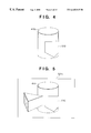
Referring to FIG. 1, if reference numeral 400 denotes an object (e.g., triangular prism-shaped block) in a real space, an augmented reality presentation system (not shown) in this example, presents an augmented reality image in which a virtual object 410 (e.g., a columnar block) is merged to a position behind the real object 400 to the observer. The augmented reality presentation system generates a depth image of the real object 400 from images taken by a camera that moves together with the observer, and discriminates the depth ordering of the real object 400 and virtual object 410 on the basis of this depth image upon presenting an image of the virtual object 410.
Assume that the observer has moved his or her viewpoint to P1, P2, P3, and P4 in turn, and is currently at a viewpoint P5. At the viewpoint P5, the observer must be observing a scene 500 5.
If a depth image of the scene 500 5 (a depth image 510 5 of the scene 500 5 obtained by observation from the viewpoint P5) is obtained, the augmented reality presentation system can generate a virtual image 410 5 with an occluded portion 600, and can render these images in a correct occlusion relationship, i.e., can render a scene 520 5 (FIG. 3) in which the virtual image 410 is partially occluded by the object 400.
However, since this augmented reality presentation system requires a time Δt for its internal processing, a depth image to be used at the viewpoint P5 for augmented reality presentation is the one at an old viewpoint Δt before the viewpoint P5 (the viewpoint P2 in FIG. 1 will be used to express this old position for the sake of simplicity). That is, at the current time (i.e., the time of the viewpoint P5 in FIG. 1), a depth image 510 2 corresponding to a scene 500 2 at the viewpoint P2 Δt before the current time can only be obtained.
At the viewpoint P2, the object 400 could be observed at a rightward position as compared to the scene 500 5, and its depth image 510 2 could correspond to the scene 500 2. Hence, when the depth ordering of the real and virtual worlds at the viewpoint P5 is discriminated in accordance with this old depth image 510 2, since a virtual image 410 2 with an occluded portion 610, is generated, as shown in FIG. 4, an image of the front real object 400 is presented to the observer as the one which is occluded by the virtual image 410 2 of the virtual object 410, and by contrast, an image of the virtual object 410 presented to the observer has a portion 610 which ought not to be occluded but is in fact occluded, and the virtual object 410 also has a portion 620 which ought to be occluded but is in fact not occluded, as shown in FIG. 5.
In this way, if augmented reality is presented while ignoring the time Δt required for generating a depth image, an unnatural, contradictory world is presented.
As a prior art that points out problems with real-time stereo processing based on high-speed processing implemented by hardware, Yasuyuki Sugawa & Yuichi Ota, “Proposal of Real-time Delay-free Stereo for Augmented Reality” is known.
This article proposes predicting a future depth image. That is, this article proposes an algorithm that can reduce system latency from input to output as much as possible by executing high-speed disparity estimation that uses the stereo processing result of previous images and utilizes time correlation, parallel to disparity estimation by stereo.
However, this article is premised on used of a stationary camera, and cannot cope with a situation where the camera itself (i.e., a position/posture of viewpoint of the observer) moves.
SUMMARY OF THE INVENTION
The present invention has been made to solve the conventional problems, and has as its object to provide a depth image measurement apparatus and method, that can acquire a depth image of a real world in real time without any delay.
It is another object of the present invention to provide an image processing apparatus and method, which can present a three-dimensionally matched augmented reality image even when the viewpoint of the observer moves, and to provide an augmented reality presentation system and method.
It is still another object of the present invention to provide an image processing apparatus and method, which can present a three-dimensionally matched augmented reality image, continuously in particular, and to provide an augmented reality presentation system and method.
According to a preferred aspect of the present invention, the second viewpoint position at which the second depth image is to be generated is that of the image input means at the second time, to which the image input means has moved over a time elapsed from the first time at which the image input means input the stereo image.
According to a preferred aspect of the present invention, the second time is a time elapsed from the first time by
a known first processing time required for depth image processing in the calculation means, and
a second processing time required for depth image warping processing by the warping means.
According to a preferred aspect of the present invention, the image input means (or step) inputs a stereo image from stereo cameras.
According to a preferred aspect of the present invention, the depth image generation means (or step) generates the stereo image or first depth image by triangulation measurement.
The viewpoint position can be detected based on an image input by the image input means without any dedicated three-dimensional position/posture sensor. According to a preferred aspect of the present invention, the position information estimation means (or step) estimates changes in viewpoint position on the basis of the stereo image input from the stereo cameras attached to the observer.
The viewpoints can be accurately detected using a dedicated position/posture sensor. According to a preferred aspect of the present invention, the position information estimation means (or step) receives a signal from a three-dimensional position/posture sensor attached to the camera, and estimates changes in viewpoints on the signal.
According to a preferred aspect of the present invention, the depth image warping means (or step) calculates a coordinate value and depth value of one point on the second depth image, which corresponds to each point on the first depth image, by three-dimensional coordinate transformation on the basis of the viewpoint position/posture information.
Other features and advantages of the present invention will be apparent from the following description taken in conjunction with the accompanying drawings, in which like reference characters designate the same or similar parts throughout the figures thereof.
BRIEF DESCRIPTION OF THE DRAWINGS
FIG. 1 is a view for explaining conflict or mismatching produced upon generating an augmented reality image based on a depth image obtained by a conventional method;
FIG. 2 is a view for explaining the reason why conflict or mismatching is not produced, assuming that the augmented reality image shown in FIG. 1 is free from any latency time;
FIG. 3 is a view for explaining the reason why conflict or mismatching is not produced, assuming that the augmented reality image shown in FIG. 1 is free from any latency time;
FIG. 4 is a view for explaining the reason why conflict or mismatching has been produced when the augmented reality image shown in FIG. 1 has latency time;
FIG. 5 is a view for explaining the reason why conflict or mismatching has been produced when the augmented reality image shown in FIG. 1 has latency time;
FIG. 6 is a block diagram of an image processing apparatus 200 according to an embodiment to which the present invention is applied and the first embodiment;
FIG. 7 is a timing chart for explaining the operation of the image processing apparatus 200 according to the embodiment and the first embodiment when the internal processing of the apparatus 200 is done in a pipeline fashion;
FIG. 8 is a view for explaining the relationship between positions (X, Y, Z) as well as postures (ω, ψ, κ) of viewpoints in the embodiment, and the first to third embodiments;
FIG. 9 is a flow chart showing the control sequence of a viewpoint position/posture estimation module 201 according to the first embodiment of the present invention;
FIG. 10 is a view for explaining the principle of computation for synchronization when the sensor output and camera output are not synchronized in the first embodiment of the present invention;
FIG. 11 is a flow chart for explaining the operation sequence of a depth estimation module 202 according to the first embodiment of the present invention;
FIG. 12 is a view for explaining the operation principle of a depth warping module 203 of the first embodiment;
FIG. 13 is a view for explaining the operation principle of the depth warping module 203 of the first embodiment;
FIG. 14 is a flow chart for explaining the operation sequence of the depth warping module 203 of the first embodiment;
FIG. 15 is a timing chart for explaining an example of the operation of the first embodiment;
FIG. 16 is a block diagram for explaining the arrangement of an augmented reality presentation system to which an image processing apparatus according to the second embodiment of the present invention is applied;
FIG. 17 is a block diagram showing the arrangement of an image generation module 300 in the image processing apparatus of the second embodiment;
FIG. 18 is a block diagram for explaining the arrangement of an augmented reality presentation system to which an image processing apparatus according to the third embodiment of the present invention is applied;
FIG. 19 is a view for explaining another viewpoint position/posture estimation method in the third embodiment;
FIG. 20 is a block diagram showing the arrangement of an image generation module 300 in the image processing apparatus of the third embodiment;
FIG. 21 is a timing chart for explaining the operation of the third embodiment;
FIG. 22 is a flow chart showing the control sequence of viewpoint position/posture estimation according to the other method; and
FIG. 23 is an illustration showing the control sequence of viewpoint position/posture estimation according to still another method.
DETAILED DESCRIPTION OF THE INVENTION
A depth image generating apparatus for generating a depth image according to a preferred embodiment of the present invention will be explained hereinafter with reference to the accompanying drawings.
<Principle>
FIG. 6 shows a basic arrangement of a depth image generation apparatus, and mainly shows a depth image generation apparatus 200 having two cameras 102R and 102L mounted on a base 100.
The base 100 has the two cameras 102R and 102L for stereoscopically sensing a scene in front of them. Image signals IR and IL that represent an environmental scene of a real space sensed by the respective cameras at time t0 are sent to the depth image generation apparatus 200. The depth image generation apparatus 200 has a depth estimation module 202 for receiving these image signals IR and IL and extracting a depth image ID (three-dimensional shape information Z) of the environmental scene, a module 201 for estimating the relative position/posture of the viewpoint of the camera 102R at future time tF (=t0+Δt), and a depth warping module 203 for warping the depth image estimated by the module 202 to a depth image IDW at that viewpoint.
The viewpoint position/posture estimation module 201 outputs the relative position/posture of the viewpoint at time tF viewed from the viewpoint position/posture at time t0 to the depth warping module 203.
The viewpoint position/posture estimation module 201 has two input routes. One input route receives position information (x, y, z) and posture information (ω, ψ, κ) from a three-dimensional position/posture sensor 101 mounted on the base 100. Note that the position information (x, y, z) and posture information (ω, ψ, κ) will be generally referred to as “position/posture information V” hereinafter. The other input route to the viewpoint position/posture estimation module 201 receives the image signal IR from the camera 102R.
The three-dimensional position/posture sensor 101 is mounted on the base 100, and is calibrated to output the viewpoint position/posture of the camera 102R. That is, the relative position relationship (offset) between the sensor itself and camera 102R is measured in advance, and this offset is added to the position/posture information of the sensor itself as its actual output, thus outputting the position/posture information V of the camera 102R.
When the viewpoint position/posture estimation module 201 receives the position/posture information V (x, y, z, ω, ψ, κ) from the sensor 101, that information V represents the viewpoint position/posture of the camera 102R. On the other hand, when the viewpoint position/posture estimation module 201 receives the image signal IR, it extracts the position/posture information V of the camera 102R from that image signal IR. In this way, the viewpoint position/posture estimation module 201 time-sequentially extracts the position/posture information V of the camera 102R on the basis of the signal time-sequentially input from one of the sensor 101 and camera 102R.
Furthermore, the viewpoint position/posture estimation module 201 estimates a change ΔV in relative viewpoint position of the camera 102R at time tF, viewed from the viewpoint position of the camera 102R at time t0, on the basis of the time-sequentially extracted position/posture information V of the camera 102R, and outputs it.
The feature of the depth image generation apparatus 200 shown in FIG. 6 lies in that the change ΔV in viewpoint at arbitrary future time tF is estimated and a depth image IDW at that viewpoint position/posture is generated. The depth warping module 203 warps the depth image ID estimated by the depth estimation module 202 to generate a depth image IDW. This warping will be explained in detail later.
Time Δt can be arbitrarily set. Assume that image captured by the cameras 102 requires a processing time δ1, the depth estimation module 202 requires a processing time δ2, and the depth warping module 203 requires a processing time δ3. For example, by setting time tF:
t F =t 0123 =t 0 +Δt  (1)
for Δt≡δ123, the output time of the depth image IDW can be matched with time tF (that is, a depth image free from any delay can be obtained).
The basic principle of the depth image generating apparatus to which the present invention is applied has been described.
The image generating apparatus shown in FIG. 6 can improve processing efficiency by pipeline processing exploiting its hardware arrangement.
FIG. 7 shows the pipeline order when the pipeline processing is applied to the image generating apparatus shown in FIG. 6.
More specifically, at arbitrary time t0 (assumed to be the current time), the two cameras 102 inputs two, right and left image signals IR and IL. Assume that this input processing requires a time δ1. Then, at time t012, the depth estimation module 202 outputs a depth image ID at time t0 to the depth warping module 203.
On the other hand, the viewpoint position/posture estimation module 201 obtains the current viewpoint position/posture Vt0 from that image signal (or the signal from the position/posture sensor), estimates a viewpoint position/posture VtF Δt after the current time from the locus of the viewpoint so far, and outputs a change ΔV in viewpoint position/posture between these two viewpoints. Assume that the position/posture estimation module 201 requires a time δ0 for this estimation (see FIG. 7) (at this time, assume that the time δ0 is sufficiently shorter than the time δ2). Hence, by starting a viewpoint position/posture estimation at time t012−δ0, the change ΔV in viewpoints is output to the depth warping module 203 at time t012.
When the timing at which the position/posture estimation module 201 outputs the estimation result cannot be synchronized with the timing at which the depth warping module 203 receives the estimation result, the position/posture estimation module 201 or depth warping module 203 may include a buffer memory for temporarily storing the estimation result.
The depth warping module starts warping at time t012. More specifically, the depth warping module 203 starts processing for warping the estimated depth image ID at time t0 by the depth estimation module 202 to a depth image at the estimated viewpoint at time t0+Δt by the position/posture estimation module 201. If the depth warping module 203 requires a time δ3 for the processing, it outputs the warped depth image IDW at time t0123.
As shown in FIG. 7, the position/posture estimation module 201 and depth estimation module 202 execute parallel processes.
On the other hand, the processes of the depth estimation module 202 and depth warping module 203 can be coupled in a pipeline fashion.
More specifically, when the depth image generation apparatus 200 is applied to a plurality of continuously input frame images, the depth estimation module 202 continuously and sequentially receives images. For example, when images are input at a rate of 30 frames/sec, the depth estimation module 202 must process, within the time δ2 required for the processing:
30×δ2 frames
For this purpose, the depth estimation module 202 is further divided into a plurality of module units. If the module 202 is divided so that its processing is done by distributed processing using a maximum of 30×δ2 module units, the depth estimation module 202 can continuously estimate depth images at the rate of 30 frames/sec. Similarly, the depth warping module is divided in accordance with the time δ3 required for its processing. With such divided module units, the depth image generation apparatus 200 of this embodiment can continuously execute two processes, i.e., depth estimation and depth warping, in a pipeline fashion.
When the divided module units must be synchronized, a buffer memory or memories can be appropriately added, as described above.
In FIG. 6, the depth estimation module 202 and depth warping module 203 generate a depth image on the basis of an image from one camera, but they may generate depth images on the basis of images from two cameras, depending on the purposes.
Also, in FIG. 6, the number of cameras 102 is not limited to two. In order to improve depth estimation precision, two or more cameras are preferably used.
The depth image generation apparatus 200 shown in FIG. 6 is designed to require the time duration Δt the length of which is set δ123. However, ideally, the time duration Δt should be determined depending on the time when a depth image is required by an application. However, estimation in the position/posture estimation module 201 suffers more errors as the time duration Δt becomes larger, and this tendency becomes especially conspicuous when the moving speed of the observer is high or when the moving direction is random.
That is, both too small and large Δt lead to an increase in error. More specifically, the time duration Δt must be appropriately adjusted in correspondence with the use environment of that system or the purpose of an application which uses the output depth image. In other words, a depth image suffering least errors can be output by allowing the user to freely set optimal Δt.
How the apparatus of the embodiment shown in FIG. 6 removes conflict produced upon discriminating the depth ordering in the prior art that has been described above with the aid of FIG. 1 will be explained below.
In order to present augmented reality free from any conflict in terms of the depth ordering, a depth image at the viewpoint position/posture (a view-point P5 in the example in FIG. 1) of the observer at the presentation time of the generated augmented reality image must be used. More specifically, if δ4 represents the processing time required from when the image processing apparatus shown in FIG. 6 outputs a warped depth image until an augmented reality image that takes that depth into consideration is presented to the observer, Δt can be ideally set to be:
Δt=δ 1234  (2)
Thus, referring to FIG. 1, the current time is t5 at the viewpoint P5, and the time t2 is Δt prior to the current time. Then, the position/posture estimation module 201 in the image processing apparatus shown in FIG. 6 predicts a position/posture of viewpoint at the time Δt after the current time, the prediction being made at time t212−δ0 in FIG. 1. On the other hand, the depth warping module 203 warps a depth image 510 2 at the viewpoint P2 obtained by the depth estimation module 202 to a depth image which will be obtained at the predicted viewpoint (i.e., the viewpoint P5) the time Δt after the current time. Hence, the depth warping module 203 is expected to output the warped depth image (this depth image is similar to the depth image 510 5) at time t5−δ4. Hence, when a virtual object is rendered while discriminating the depth ordering based on this warped depth image, and is presented to the observer, an augmented reality image can be projected to the observer's eyes so that a virtual object 410 has correct depth ordering with a real object 400.
More specifically, in order to obtain an augmented reality free from any latency or time delay by measuring a depth image based on an image obtained by the moving camera, estimation of the depth image 510 5 must be started at time t2 the time duration At required for the internal processing before time t5. In other words, when an image is input from the camera at time t2, the depth image 510 5 starts to estimate the depth image 510 5 of the real space at time t5. The depth image generation apparatus 200 shown in FIG. 6 warps the depth image 510 2 of an image input from the camera at time t2, and uses the warped depth image as the depth image 510 5 of the real space at time t5.
<Embodiments>
Three embodiments of apparatuses to which the principle of the embodiment that has been described with reference to FIGS. 6 and 7 will be described below.
An apparatus of the first embodiment is a depth image generation apparatus that explains the principle of the embodiment shown in FIGS. 6 and 7 in more detail.
In apparatuses of the second and third embodiments, the principle of the embodiment that generates a depth image in real time without any latency or time lag from the real space is applied to an augmented reality presentation system. More specifically, the second embodiment is directed to an optical see-through augmented reality presentation system using an optical see-through HMD, and the third embodiment is directed to a video see-through augmented reality presentation system using a video see-through HMD.
<First Embodiment>
The arrangement and operation of the first embodiment will be explained below with the aid of FIG. 6.
FIG. 6 is a block diagram of a depth image generation apparatus of the first embodiment. In the aforementioned basic embodiment suggests applications with and without the three-dimensional position/posture sensor 101. In the description of the first embodiment, the three-dimensional position/posture sensor 101 is used.
<Operation of Viewpoint Position/Posture Estimation Module 201> . . . First Embodiment
The operation of the position/posture estimation module 201 of the first embodiment will be described below.
The position/posture sensor 101 continuously outputs viewpoint position/posture information Vts of the camera 102 along a time axis ts of the sensor 101. The position/posture information Vts along the time axis ts of the sensor is given by:
V ts ={x ts , y ts , z ts, ωts, ψts, κts}  (3)
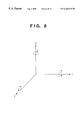
Note that ω, ψ, and κ are respectively the rotational angles about the X-, Y-, and Z-axes, as shown in FIG. 8. A viewing transformation matrix (i.e., a transformation matrix from a world coordinate system to a camera coordinate system) Mts corresponding to such viewpoint position/posture Information Vts is given by: M ts = [ cos κ ts - sin κ ts 0 0 sin κ ts cos κ ts 0 0 0 0 1 0 0 0 0 1 ] · [ 1 0 0 0 0 cos ω ts - sin ω ts 0 0 sin ω ts cos ω ts 0 0 0 0 1 ] · [ cos ψ ts 0 sin ψ ts 0 0 1 0 0 - sin ψ ts 0 cos ψ ts 0 0 0 0 1 ] · [ 1 0 0 - x ts 0 1 0 - y ts 0 0 1 - z ts 0 0 0 1 ] ( 4 )
Figure US06445815-20020903-M00001
FIG. 9 shows the control sequence of the viewpoint estimation module 201.
In step S2, position/posture information Vtsm at current time tsm along the time axis of the sensor is input from the sensor 101. In this way, together with previously input position/posture information, a series of position/posture information is obtained:
V ts0 , V ts1 , V ts2 , . . . , V tsm
The output from the position/posture sensor 101 is according to the time axis ts. When the camera 102 is synchronized with the sensor 101, position/posture information at time t0 at which the camera 102 captured the image can be directly used. On the other hand, when these two devices are not in phase, the position/posture information at time t0 is calculated by interpolating position/posture information obtained from the sensor before and after that time. This interpolation can be implemented by, e.g., simple a 1st-order (linear) interpolation. More specifically, when time t0 has a relationship with time ts of the sensor 101, as shown in FIG. 10, in step S4 using tsn and tsn+1, and k (0≦k≦1), t0 is given by:
t 0=(1−kt sn +k·t sn+1  (5)
Solving equation (5) yields k. That is, k represents the relationship between the time systems of the camera and sensor. In step S6, a position Vt0 of the camera 102R at time t0 is calculated according to equation (6) below using the obtained k:
V t0 ={x t0 , y t0 , z t0, ωt0, ψt0, κt0}
where
x t0=(1−kx tsn +k·x tsn+1
y t0=(1−ky tsn +k·y tsn+1
z t0=(1−kz tsn +k·z tsn+1
ωt0=(1−k)·ωtsn +k·ω tsn+1
ψt0=(1−k)·ψtsn +k·ψ tsn+1
κt0=(1−k)·κtsn +k·κ tsn+1  (6)
Subsequently, in step S8, position/posture information VtF of the camera 102R at time tF (=t0+Δt) is estimated.
Assume that the position/posture information of the camera 102R is obtained up to tsm as a position series, as shown in FIG. 10. If time tF is given by:
t F =t sm +α·Δt s  (7)
(for Δts=tsm−tsm−1), α can be determined from this relationship. In step S8, the viewpoint position/posture information VtF of the camera 102R at time tF is given, using, e.g., 1st-order linear prediction, by:
V tF ={x tF , y tF , z tF, ωtF, φtF, κtF}  (8)
where
x tF =x sm+α·(x sm −x sm−1)
y tF =y sm+α·(y sm −y sm−1)
z tF =z sm+α·(z sm −z sm−1)
ωtFsm+α·(ωsm−ωsm−1)
φtFsm+α·(φsm−φsm−1)
κtFsm+α·(κsm−κsm−1)
Note that the viewpoint having position/posture value VtF may be estimated by 2nd-order linear prediction or other prediction methods.
Finally, in step S10, a three-dimensional motion of the viewpoint position of the camera from time t0 to time tF is estimated. This three-dimensional motion is represented by a matrix ΔM given by:
ΔM=M tF·(M t0)−1  (9)
where Mt0 is the transformation matrix from the world coordinate system into the camera coordinate system of the camera 102R at time t0, and MtF is the transformation matrix from the world coordinate system of the camera 102R at time tF. Also, (Mt0)−1 is the inverse matrix of Mt0. More specifically, ΔM is the transformation matrix from the camera coordinate system of the camera 102R at time t0 to the camera coordinate system of the camera 102R at time tF.
In step S12, this transformation matrix ΔM is output.
<Depth Estimation Module 202> . . . First Embodiment
The depth estimation module 202 receives image signals IR and IL from the cameras 102R and 102L, and calculates depth information by known triangulation measurement.
FIG. 11 shows the control sequence of the depth estimation module 202. More specifically, in step S20, corresponding points existing between the two images IR and IL are extracted from the individual images. Pairs of corresponding points are pixels of points on the right and left images, which respectively correspond to a given point on an object. Such corresponding point pairs must be obtained by search in correspondence with all the pixels or feature pixels in the images IR and IL. In step S22, a depth value Zi of a given point viewed from the camera 102R is calculated using triangulation measurement method for a pair of pixels (XRi, YRi) and (XLi, YLi) as corresponding points in the images IR and IL. In step S24, the obtained depth value Zi is stored in a coordinate position (XRi, YRi) of the depth image ID.
The depth values for all the points are calculated by repeating a loop of steps S20 to S26. That is, the depth image ID is generated. The generated depth image ID is output to the depth warping module 203.
Note that the depth estimation module 202 can be implemented using, e.g., a method disclosed in “CMU Video-Rate Stereo Machine” mentioned above, an active range finder, or a scheme proposed by Yasuyuki Sugawa, et al., “Proposal of Real-time Delay-free Stereo for Augmented Reality” in addition to triangulation measurement.
<Depth Warping Module 203> . . . First Embodiment
As shown in FIG. 6, the depth warping module 203 warps the depth image ID at the viewpoint having position/posture value Vt0 received from the depth estimation module 202 to the depth image IDW at the viewpoint having position/posture value VtF.
The principle of processing in the depth warping module 203 is as follows. That is, the basic operation of the depth warping module 203 is to inversely project the depth image ID acquired at the viewpoint having position/posture value Vt0 into a space, and to re-project it onto an imaging plane assumed at the viewpoint having position/posture value VtF (i.e., to give a depth value ZDi to a point (xi′, yi′) on an output image corresponding to the depth image IDW)).
Let fc be the focal length of the camera 102. If an arbitrary point of the depth image ID has a value Zi=ID(xi, yi), this point (xi, yi) is transformed from a point (xi, yi, fc) on the imaging plane of the camera 102 into a point (Xi″, Yi″, Zi″) in a three-dimensional space on the camera coordinate system of the camera 102R at the viewpoint having position/posture value Vto according to the equation below, i.e., as can be seen from FIG. 12: ( X i , Y i , Z i ) = ( x i · Z i f C , y i · Z i f C , Z i ) ( 10 )
Figure US06445815-20020903-M00002
As a result of a three-dimensional motion ΔM which moves the camera 102R from the viewpoint having position/posture value Vt0 to the viewpoint having position/posture value VtF, this point (Xi″, Yi″, Zi″) is expected to move to a position (XDi, YDi, ZDi) on the camera coordinate system at the viewpoint having position/posture value VtF, which position is given by: ( X Di Y Di Z Di ) = Δ M · ( X i Y i Z i ) ( 11 )
Figure US06445815-20020903-M00003
Since this camera has the focal length fc, the point (XDi, YDi, ZDi) on the camera coordinate system at the viewpoint having position/posture value VtF is expected to be projected onto a point (xi′, yi′) on the imaging plane given by: ( x i y i ) = ( X Di Z Di · f c Y Di Z Di · f c ) ( 12 )
Figure US06445815-20020903-M00004
The depth warping module 203 outputs IDW (xi′, yi′)=ZDi as the warped depth image IDW.
FIG. 14 explains the processing sequence of the depth warping module 203.
One point (xi, yi) of the depth image ID is extracted in step S30, and is projected onto the camera coordinate system of the camera 102 at the viewpoint having position/posture value VT0 according to equation (10) above in step S32. More specifically, the coordinate position (Xi″, Yi″, Zi″) of the point (xi, yi) on the camera coordinate system is calculated. In step S34, the coordinate position (XDi, YDi, ZDi) of the point (Xi″, Yi″, Zi″), viewed from the camera coordinate system of the camera 102 at the viewpoint having position/posture value VtF is calculated using equation (11) above. Subsequently, in step S36, the position (xi′, yi′) of the warped depth image is calculated using equation (12) above. In step S38, pixels (xi′, yi′) on this output image are filled with ZDi. Such processes repeat themselves for all the pixels, thus warping the depth image.
Since one point on the non-warped depth image ID has a one-to-one correspondence with that on the warped depth image IDW, the warped depth image IDW may have “holes”. Such image having “holes” can be corrected by compensating the values of missing pixels by linear interpolation using surrounding pixels. Also, such image having “holes” can be corrected using a scheme described in Shenchang Eric Chen & Lance Williams, “View Interpolation for Image Synthesis”, Computer Graphics Annual Conference Series (Proceedings of SIGGRAPH 93), pages 279-288, Anaheim, Calif., August 1993.
<Operation Timing of First Embodiment>
FIG. 15 shows the operation timing of the image processing apparatus of the first embodiment.
The frame rates of the depth estimation module and depth warping module can be independently set. As shown in FIG. 15, when the frame rate of the depth warping module is set to be higher than that of the depth estimation module (in the example of FIG. 15, 6 times), a plurality of warped depth images IDW (six images in the example of FIG. 15) can be obtained from a single input image at high speed (6 times in the example of FIG. 15).
<Modification of First Embodiment>
In the first embodiment, an image obtained by the right camera 102R is to be processed. Alternatively, a depth image corresponding to an image sensed by the left camera 102L may be output by similar processing. Also, depth images for both the right and left cameras may be output.
<Second Embodiment>
In the second embodiment, the principle of the embodiment shown in FIG. 6 is applied to an optical see-through augmented reality presentation system.
FIG. 16 is a block diagram showing the system of the second embodiment, and the same reference numerals in FIG. 16 denote the same components as those in the embodiment shown in FIG. 6. Note that a component 100 represents an optical see-through HMD. The system of the second embodiment is constructed by the HMD 100, a depth image generation apparatus 200, an image generation module 300, and a three-dimensional CG database 301.
The HMD 100 comprises an LCD 103R for displaying a right-eye image, and an LCD 103L for displaying a left-eye image, since it is of optical see-through type. In order to accurately detect the viewpoint position, a three-dimensional position/posture sensor 101 is provided to the HMD 100.
The depth image generation apparatus 200 (FIG. 16) of the second embodiment has the following differences from the depth image generation apparatus 200 (FIG. 6) of the aforementioned embodiment. That is, first, the second embodiment requires a depth image at each viewpoint of the observer (not shown) in place of that at each viewpoint of the camera 102R. Second, depth images must be generated in correspondence with the right and left viewpoints of the observer. Furthermore, the output from a viewpoint position/posture estimation module 201 of the second embodiment is output to the image generation module 300 in addition to a depth warping module 203 unlike in the first embodiment. The position/posture estimation module 201 outputs viewpoint position/posture information of the observer upon presentation of an image to the image generation module 300.
The image generation module 300 uses the position/posture information input from the position/posture estimation module 201 as that for CG rendering. The module 300 generates an augmented reality image using the three-dimensional CG database in accordance with the distance to an object in the real world expressed by the depth image, and presents it on the LCDs 103.
Note that the three-dimensional CG database 301 stores, for example, CG data of the virtual object 410 shown in FIG. 1.
<Operation of Viewpoint Position/Posture Estimation Module 201> . . . Second Embodiment
The operation of the position/posture estimation module 201 of the second embodiment will be explained below.
The position/posture estimation module 201 of the second embodiment outputs matrices ΔMR and ΔML that represent three-dimensional motions from a viewpoint position/posture information Vt0 CR of the camera 102R at time t0 to right and left viewpoint positions VtF UR and VtF UL of the observer at time tF to the depth warping module 203. Assume that suffices C, U, R, and L respectively indicate the camera, user (observer), right, and left.
The position/posture estimation module 201 outputs the right and left viewpoint positions VtF UR and VtF UL at time tF to the image generation module 300. As shown in FIG. 16, the position/posture sensor 101 in the second embodiment outputs not only the viewpoint position/posture information Vts CR of the camera 102R but also information of the right and left viewpoint positions/postures Vts UR and Vts UL unlike in the first embodiment.
The method of calculating position/posture Vt0 CR of the camera 102R at time t0 (and a corresponding viewing transformation matrix Mt0 CR) in the second embodiment is the same as that in the first embodiment.
On the other hand, the right and left viewpoint positions/positions VtF UR and VtF UL of the observer at time tF (=t0+Δt) (and corresponding viewing transformation matrices MtF UR and MtF UL) can be estimated by equation (8) as in the first embodiment. In this case, the viewpoint position/posture is not that of a camera but of the observer.
Matrices ΔMR andΔML that represent three-dimensional motions can be calculated as in equation (9) by:
ΔM R =M tF UR·(M t0 CR)−1
ΔM L =M tF UL·(M t0 CL)−1  (13)
Since the processing of the depth estimation module 202 of the second embodiment is the same as that in the first embodiment, a detailed description thereof will be omitted.
Note that the position/posture sensor 101 may output Vts CR alone. In this case, the position/posture estimation module 201 internally calculates Vts UR and Vts UL using the relative position relationship between the camera 102R, and the right and left viewpoint positions/postures of the observer as known information.
<Depth Warping Module 203> . . . Second Embodiment
Unlike the first embodiment, depth images required as warped depth images in the second embodiment are those in the real world observed from the viewpoint position/postures of the observer via the LCDs 103. That is, when a virtual camera equivalent to the viewpoint of the observer is assumed, and fU (U is the user (observer)) represents the focal length of that virtual camera, the operation of the depth warping module 203 of the second embodiment is to inversely project a depth image ID acquired at a viewpoint having position/posture information Vt0 into a space, and to re-project it onto the imaging plane of the virtual camera with the focal length fU assumed at the viewpoint having position/posture value VtF. This operation is implemented by replacing the value of the focal length fc of the camera 102 by the focal length fU of the virtual camera in equation (12) that expresses projection to the depth image IDW.
Furthermore, compared to the first embodiment, the depth warping module of the second embodiment has the following difference. More specifically, the depth warping module of the second embodiment receives the matrices ΔMR andΔML representing two three-dimensional motions corresponding to the right and left viewpoint positions/postures as the matrix ΔM that expresses the three-dimensional motion of the viewpoint position, and outputs two depth images IDW R and IDW L corresponding to the right and left viewpoint positions/postures as the depth image IDW. These outputs can be obtained by independently warping images corresponding to the right and left viewpoints.
<Image Generation Module 300> . . . Second Embodiment
FIG. 16 shows the arrangement of the image generation module 300 of the second embodiment.
Generation of an image to be displayed on the LCD 103R, which is presented to the right eye of the observer, will be described first.
The CG renderer 302 renders a grayscale image (or color image) and depth image of CG data received from the three-dimensional database 301 on the basis of the viewpoint position/posture information VtF UR of the right eye of the observer input from the position/posture estimation module 201. The generated grayscale image (or color image) is supplied to a mask processor 303, and the depth image is supplied to a depth ordering discrimination processor 304. The depth ordering discrimination processor 304 also receives the warped depth image IDW R from the depth warping module 203. This depth image IDW R represents depth information of the real space. Hence, the depth ordering discrimination processor 304 compares the depth of a CG image to be displayed and that of the real space in units of pixels, generates a mask image in which “0” is set in all pixels corresponding to real depths smaller than the CG depths, and “1” is set in other pixels, and outputs that image to the mask processor 303.
Zero pixel value of a given coordinate position on the mask image means that a CG figure rendered at the identical coordinate position on a CG image is located behind an object in the real space, and cannot be seen since it must be occluded by that object. The mask processor 303 mask-processes the CG image on the basis of the mask image. That is, if each coordinate position on the mask image has zero pixel value, the processor 303 sets the pixel value of an identical coordinate position on the CG image at “0”. The output from the mask processor 303 is output to the display 103R. An image to be displayed on the LCD 103L which is presented onto the left eye of the observer is generated in similar processes.
To restate, according to the apparatus of the second embodiment, since mask processing is done on the basis of a depth image which is expected to be observed at time tF without being influenced by a delay produced by stereo processing upon generation of a CG image to be presented to the observer, augmented reality free from any conflict between the real space and CG image can be given.
It is also possible to generate the image to be displayed without the depth ordering discrimination processor 304 and the mask processor 303. In this case, the CG renderer 302 receives the warped depth image IDW R from the depth warping module 203. At first, the CG renderer 302 renders a black object over the image which has the depth of the depth image IDW R. Then, the CG renderer 302 renders and overlays a virtual image by using ordinal depth-keying technique.
<Modification of Second Embodiment>
In the second embodiment, theoretically it is preferable that the depth image be corrected using the viewpoint position of the observer at the presentation timing of the augmented reality image to the observer as a target viewpoint position. Let δ4 be a processing time required from when the image generation module 300 inputs the depth image IDW until the augmented reality image is presented onto the LCDs 103. Theoretically, by setting a time duration Δt required for the warp process in the depth image generation apparatus 200 to be:
Δt=δ 1234  (14)
the augmented reality image per frame to be presented to the LCDs 103 is synchronized with the real space the observer is currently observing.
In the second embodiment, a position/posture and focal length of the camera 102, and the right and left viewpoint positions/postures and focal length of the observer are independently processed. However, if the viewpoint of the observer matches the camera, they can be processed as identical ones.
In the second embodiment, different videos are presented on the right and left eyes of the observer. However, in case of an optical see-through augmented reality presentation system having a single-eye optical system, processing corresponding to only one eye of the observer need be done.
<Third Embodiment>
In the third embodiment, the principle of the embodiment shown in FIG. 6 is applied to a video see-through augmented reality presentation system, and FIG. 18 shows the arrangement of that system.
Upon comparing the constructing elements of the system of the third embodiment in FIG. 18 with those of the system of the second embodiment shown in FIG. 16, the former system is different from the latter one in that the former system has no head mounted position/posture sensor 101, and a viewpoint position/posture estimation module 201 can estimate movement of the viewpoint from an image acquired by one camera 102.
Since the third embodiment uses a video see-through HMD, the arrangement of an image generation module is also different from the second embodiment, as will be described later.
Also, since the video see-through scheme is used, some of images to be displayed on LCDs 103 are obtained from cameras 102 in the third embodiment.
<Viewpoint Position/Posture Estimation Module 201> . . . Third Embodiment
The position/posture estimation module 201 of the third embodiment outputs matrices ΔMR and ΔML that represent three-dimensional motions from a viewpoint of a camera 102R having position/posture Vt0 CR at time t0 to right and left viewpoints of right and left cameras 102R and 102L having positions/postures VtF CR and VtF CL at time tF, to a depth warping module 203. Furthermore, the module 201 outputs the viewpoint positions/postures VtF CR and VtF CL of the right and left cameras 102R and 102L at time tF to an image generation module 300.
The position/posture estimation module 201 in the first and second embodiments detects viewpoint positions/postures on the basis of the output from the position/posture sensor 101. However, the position/posture estimation module 201 of the third embodiment estimates movement of the viewpoint on the basis of images input from the cameras 102R and 102L.
Various schemes for estimating viewpoint position/posture on the basis of image information are available. For example, by tracking changes in coordinate value of feature points, the position on the real space of which is known, in an image, movement of the viewpoint position can be estimated. For example, in FIG. 19, assume that an object 600 present in the real space has vertices Q1, Q2, and Q3 as feature points. The coordinate values of these vertices Q1, Q2, and Q3 on the real space are known. A viewpoint represented by Vt1 can be calculated from the coordinate values of the vertices Q1, Q2, and Q3 at time t1 and the known coordinate values of these vertices on the real space. Even when an image shown in FIG. 19 is obtained at time t2 as a result of movement of the camera, a viewpoint position/posture information Vt2 can be similarly calculated.
The number of known feature points used in the above scheme must be changed depending on the algorithms used. For example, an algorithm described in U. Neumann & Y. Cho, “A self-tracking augmented reality system”, Proceedings VRST '96, pages 109-115, 1996 requires three feature points, or an algorithm described in Nakazawa, Nakano, Komatsu, & Saito, “Moving Image Synthesis System of Actually Taken Image and CG image Based on Feature Points in Image”, the Journal of Society of Video Information Media, Vol. 51, No. 7, pages 1086-1095, 1997 requires four feature points. Also, a scheme for estimating a viewpoint position from two videos sensed by the right and left cameras 102 (e.g., A. State et al., “Superior augmented reality registration by integrating landmark tracking and magnetic tracking”, Proceedings SIGGRAPH '96, pages 429-438, 1996) may be used.
In this way, after the position/posture estimation module 201 of the third embodiment has acquired position/posture information VtC0, . . . , VtCm of viewpoints of the camera 102R at times tC0, . . . , tCm, it outputs matrices ΔM (ΔMR and ΔML) that describe three-dimensional movements of the cameras and the viewpoint positions/postures MtF (MtF CR and MtF CL) of the cameras 102 to the depth warping module 203 and image generation module 300, respectively.
Note that the processing of the depth estimation module 202 of the third embodiment is the same as that in the first embodiment, and a detailed description thereof will be omitted.
<Depth Warping Module 203> . . . Third Embodiment
The depth warping module in the third embodiment receives the matrices ΔMR and ΔML representing two three-dimensional motions corresponding to the positions/postures of right and left viewpoints as the matrix ΔM expressing a three-dimensional motion of viewpoint, and then outputs two depth images IDW R and IDW L corresponding to the positions/postures of right and left viewpoints as the depth image IDW, as in the second embodiment. However, since the viewpoint positions/postures are those of the cameras 102, the value of the focal length fC of each camera 102 can be used as the focal length in equation (12) that expresses projection onto the depth image IDW.
<Image Generation Module 300> . . . Third Embodiment
FIG. 20 shows the arrangement of the image generation module 300 of the third embodiment. Upon comparison with the image generation module 300 (FIG. 17) of the second embodiment, a CG renderer 302 and depth ordering discrimination processor 304 of the third embodiment are substantially the same as those in the second embodiment. On the other hand, a merge processor 305 merges and outputs real images and images from the CG renderer 302 unlike in the second embodiment.
The CG renderer 302 of the third embodiment renders a grayscale image (or color image) and depth image of CG data received from a three-dimensional database 301 on the basis of the viewpoint position/posture information VtF CR of the camera 102R input from the position/posture estimation module 201. The generated grayscale image (or color image) is sent to the merge processor 305 and the depth image is sent to the depth ordering discrimination processor 304.
It is also possible to generate the image to be displayed without the depth ordering discrimination processor 304 and the merge processor 305. In this case, the CG renderer 302 receives the warped depth image IDW R from the depth warping module 203 and real grayscale image (or color image) from the camera. At first, the CG renderer 302 renders a real grayscale image (or color image) which has the depth of the depth image IDW R. Then, the CG renderer 302 renders and overlays a virtual image by using ordinal depth-keying technique.
Since the processing of the depth ordering discrimination processor 304 is the same as that in the second embodiment, a detailed description thereof will be omitted. However, in the third embodiment, the image output from the depth ordering discrimination processor 304 is referred to not as a mask image but as a depth ordering discriminated image.
The merge processor 305 merges the CG image (grayscale or color image) input from the renderer 302 and a real grayscale images (or color image) from the camera on the basis of the depth ordering discriminated image. That is, if each coordinate position on the depth ordering discriminated image has a pixel value “1”, the processor 305 sets the pixel value at the identical coordinate position on the CG image to be that at the identical coordinate position on an output image; if the pixel value is zero, the processor 305 sets the pixel value at the identical coordinate position on the real image to be that at the identical coordinate position on the output image. The output from the merge processor 305 is supplied to the displays 103.
In the third embodiment, theoretically it is preferable that the viewpoint position of the camera at the input timing of a real image to be merged be set as the viewpoint position/posture information VtF.
As described above, according to the apparatus of the third embodiment, since merging is done based on a depth image that is synchronized with the input time of the real space image to be merged without being influenced by a delay produced by stereo processing, augmented reality free from any conflict between the real image space and CG image can be given, as in the second embodiment.
Since the third embodiment estimates the viewpoint position on the basis of an image from the camera, it is suitable for a video see-through augmented reality presentation system.
FIG. 21 explains the operation timing of the third embodiment.
<Modification 1>
The second and third embodiments have explained application to depth ordering discrimination between the real world and virtual image in the augmented reality presentation system. However, a depth image measurement apparatus of the present invention can also be applied to collision discrimination between the real world and virtual image in the augmented reality presentation system.
Furthermore, the depth image measurement apparatus of the present invention can also be used in applications such as an environment input apparatus for a moving robot and the like, which must acquire depth information of the real environment in real time without any delay.
<Modification 2>
The position/posture estimation module 201 in the third embodiment can also estimate the viewpoint position/posture at time tF by two-dimensional displacements of feature points on an image.
FIG. 22 shows the control sequence of the position/posture estimation module 201 upon two-dimensionally extracting feature points.
In step S40, images are input from the camera 102 in turn. Assume that the camera 102 has sensed images ItC0, ItC1, ItC2, . . . at times tC0, tC1, tC2, . . . From these input images, a sequence of coordinate values PA tC0, PA tC1, PA tC2, . . . of feature point A are obtained in step S42. In step S44, a coordinate value pA tF of feature point A at time tF is estimated. For example, this estimation may be implemented by 1st-order (linear) prediction. More specifically, assuming that the coordinate values PA tCm of feature points A on the image until time tCm has been input at the current time, if:
t F =t Cm+α·(t Cm −t Cm−1)  (15)
then PA tF=(XA tF, YA tF) satisfies:
x A t F=(1+α)·x A tCm −α·x A tCm−1
y A t F=(1+α)·y A tCm −α·y A tCm−1  (16)
The aforementioned processing is done for feature points B, C, . . . , and in step S46 the position/posture information VtF at time tF is estimated using the coordinate values PA tF, PB tF, PC tF, . . . obtained in step S44.
<Modification 3>
The viewpoint position/posture estimation module in the first or second embodiment uses information from the three-dimensional position/posture sensor, and that in the third embodiment uses image information from the cameras. However, these embodiments can be practiced using either scheme. Further, both three-dimensional position/posture sensor and camera may be used together in a modification. In this connection, a method disclosed in Japanese patent application Hei 10-65824 may be applied to the modification. The application is incorporated herewith by reference.
<Modification 4>
When a viewpoint position/posture is estimated based on image features in the estimation module of the embodiments or first embodiment, even if the position of a feature point on the real space is unknown, a three-dimensional motion ΔM of the viewpoint position/posture required for warping a depth image can be obtained.
For example, assume that a plurality of images IiC0, IiC1, . . . , IiCm have been sensed at times tC0 (=t0) tC1, . . . , tCm, as shown in FIG. 23. At this time, the image coordinate values (PA tC0, PA tC1, . . . , PA tCm; PB tC0, PB tC1, . . . , PB tCm; PC tC0, PC tC1, . . . , PC tCm) of a plurality of feature points (three points in FIG. 23) are tracked from the individual images, and the image coordinate values (PA tF, PB tF, and PC tF) of the respective feature points at time tF are estimated by the same scheme as in equation (13).
Based on a set of image coordinate values of these feature points, a relative change ΔM in viewpoint from time t0 to time tF can be directly estimated. More specifically, for example, factorization (Takeo Kaneide et al., “Recovery of Object Shape and Camera Motion Based on Factorization Method”, Journal of Institute of Electronics, Information and Communication Engineers D-II, No. 8, pages 1497-1505, 1993), Sequential Factorization (Toshihiko Morita et al., “A Sequential Factorization Method for Recovering Shape and Motion From Image Streams”, IEEE Trans. PAMI, Vol. 19, No. 8, pages 858-867, 1998), and the like may be used.
In this case, there is no need for any knowledge about an environment, and feature points may be unknown ones as long as they can be identified among images by image processing.
<Modification 5>
In the basic embodiment or the embodiments, the depth estimation module may output depth images IDC1, IDC2, . . . corresponding to images sensed by a plurality of cameras.
In this case, the viewpoint position/posture estimation module outputs matrices ΔMC1, ΔMC2, . . . that represent three-dimensional motions from the viewpoints having values Vt0 C1, Vt0 C2, . . . where the respective depth images were sensed to the viewpoint having position/posture value VtF, and the depth warping module can obtain the warped depth image IDW using such information.
More specifically, the depth warping module warps the input depth images to generate warped depth images IDW C1, IDW C2, . . . and combines these images, thus generating a warped depth image IDW as an output. Alternatively, the depth image IDW may be generated based on a depth image IDCn acquired at a viewpoint (e.g., Vt0 Cn) with smallest three-dimensional motion, and only pixels of “holes” generated at that time may be filled using information of other depth images.
<Modification 6>
When a plurality of warped depth images must be generated like in the second and third embodiments, the viewpoint position/posture estimation module may output only a matrix ΔM that represents a three-dimensional motion of a typical viewpoint position (of, e.g., the right camera 102R). In this case, the depth warping module internally calculates the matrix ΔM that represents each three-dimensional motion on the basis of the relative positional relationship among the viewpoint positions.
<Modification 7>
In the above basic embodiment or embodiments, an image to be output by the depth image generation apparatus need not always indicate the depth value itself of the real space. More specifically, for example, a disparity image that holds disparity information having a one-to-one correspondence with depth information may be output. Computations in such case can be easily implemented on the basis of the correspondence between depth information and disparity information, which is normally used in a stereo image measurement.
<Modification 8>
In the above embodiments, warping of depth images by the depth warping modules are performed in a three-dimensional fashion on the basis of the matrices _M representing three-dimensional motions and depth values of pixels. The warping according to the above method can be made in more simplified manner.
For example, warped depth images IDW can be obtained by subjecting depth images ID to translation of two dimensional axis of image plane. This process is realized by selecting representative points of objects of interest in the depth image (objects which can be used for discriminating depth ordering with respect to imaginary objects), calculating image coordinate of the points which are subjected to viewpoint translation, and subjecting the entire depth image ID to similar translation of axis.
Warped depth image IDW can be obtained by assuming that the real space is a plane having depths of representative points, and subjecting the image ID to three-dimensional rotation and translation of axis. Also, the image ID may be divided into a plurality of layers having a representative depth, and warped depth image IDW can be obtained by subjecting each layer to three-dimensional transform.
Simplifying three-dimensional shape of the objects makes calculations easier, thus providing a quicker performance of processing. However, this results in approximated depth image. Where movements of viewpoint is very small, a shape of real world is not complex, or an application does not require high precision of depth image, these approximation above described are useful.
To recapitulate, according to the depth image measurement apparatus and method of the present invention, depth images of the real world can be acquired in real time without any delay.
Also, according to the image processing apparatus and method, and the augmented reality presentation system and method of the present invention, even when the viewpoint of the observer changes, a three-dimensionally matched augmented reality image can be presented.
Furthermore, according to the image processing apparatus and method, and the augmented reality presentation system and method of the present invention, three-dimensionally matched augmented reality images can be especially continuously presented.
As many apparently widely different embodiments of the present invention can be made without departing from the spirit and scope thereof, it is to be understood that the invention is not limited to the specific embodiments thereof except as defined in the appended claims.

Claims (49)

What is claimed is:
1. A depth image measurement apparatus for acquiring depth information of a scene, comprising:
image input means for inputting an image of the scene at a first viewpoint;
depth image generation means for generating a first depth image from the scene image inputted at the first viewpoint by said image input means;
position/posture estimation means for estimating, based on information relating to displacement of the first viewpoint, a position and posture information at a second viewpoint viewed from a position and posture of the first viewpoint; and
warping means for warping the first depth image generated by said depth image generation means to a second depth image at the second viewpoint on the basis of the position and posture information at the second viewpoint estimated by said position/posture estimation means.
2. A depth image measurement apparatus for continuously acquiring depth information of a scene, comprising:
image input means for inputting a sequence of images of the scene at a first sequence of viewpoints;
depth image generation means for generating a first sequence of depth images from the scene images sequentially input at said first sequence of viewpoints by said image input means;
position/posture estimation means for estimating, based on information relating to displacement of the first viewpoint, a sequence of viewpoint position/posture information of a second sequence of viewpoints viewed from the first sequence of viewpoints; and
warping means for sequentially warping the first sequence of depth images generated by said depth image generation means to a second sequence of depth images at the second sequence of viewpoints on the basis of the viewpoint position/posture information of the second sequence of viewpoints estimated by said position/posture estimation means.
3. The apparatus according to claim 2, wherein each one of the second sequence of viewpoints is a viewpoint where said image input means has reached at a second time after an elapse of a time from a first time at which said input means input a scene image at a respective viewpoint of the first sequence of viewpoints.
4. The apparatus according to claim 3, wherein the second time is a time at which said depth image measurement apparatus outputs the second depth image.
5. The apparatus according to claim 3, wherein the second time is a time at which an apparatus connected to said depth image measurement apparatus finally uses a result of processing that uses the second depth image.
6. The apparatus according to claim 3, wherein the second time is a time at which said warping means receives the first depth image.
7. The apparatus according to claim 4, wherein a time duration between the first and second times is known in advance.
8. The apparatus according to claim 3, wherein the second time can be freely set at a time after the first time.
9. The apparatus according to claim 2, wherein each one of the second sequence of viewpoints is a viewpoint obtained by adding an offset to a respective viewpoint of said image input means, said offset relating to a position and posture of a three-dimensional sensor for sensing observer's viewpoint.
10. The apparatus according to claim 3, wherein each one of the second sequence of viewpoints is a viewpoint obtained by adding an offset to a viewpoint position and posture of said image input means at the second time, said offset relating to a position and posture of a three-dimensional sensor for sensing observer's viewpoint.
11. The apparatus according to claim 9, further comprising a plurality of sensors for sensing observer's viewpoint, wherein an offset is set to each one of the sensors.
12. The apparatus according to claim 9, wherein an amount of the offset is known in advance.
13. The apparatus according to claim 1, wherein the first viewpoint occurs at a plurality of viewpoints,
said depth image generation means generates a first depth image in correspondence with each respective first viewpoint,
said position/posture estimation means estimates viewpoint position/posture information of the second viewpoint viewed from each first viewpoint, and
said warping means warps each of the first depth image on the basis of each viewpoint position/posture information, and outputs the second depth image.
14. The apparatus according to claim 2, wherein said image input means inputs images from a plurality of video cameras.
15. The apparatus according to claim 14, wherein said depth image generation means generates the first depth image by performing stereo image processing for the images input by said image input means.
16. The apparatus according to claim 2, wherein said depth image generation means generates the first depth image using an active range finder.
17. The apparatus according to claim 2, wherein said position/posture estimation means estimates the sequence of viewpoint position/posture information on the basis of the image input by said image input means.
18. The apparatus according to claim 2, wherein said position/posture estimation means extracts image coordinate positions of feature points from the images sequentially input by said image input means, and estimates the sequence of viewpoint position/posture information using the image coordinate of the feature points.
19. The apparatus according to claim 18, wherein said position/posture estimation means includes:
recovery means for recovering a time-sequential locus of a viewpoint on the basis of the images sequentially input by said image input means, and
said position/posture estimation means estimates the sequence of viewpoint position/posture information on the basis of the locus.
20. The apparatus according to claim 19, wherein said recovery means recovers the locus of the viewpoint on the basis of time-sequential information of images input by said image input means.
21. The apparatus according to claim 19, wherein said recovery means recovers the locus of the viewpoint on the basis of information of each image input by said image input means.
22. The apparatus according to claim 18, wherein said position/posture estimation means estimates the image coordinate positions of the feature points at the second viewpoint position on the basis of images sequentially input by said image input means, and
estimates the sequence of viewpoint position/posture information on the basis of the estimated image coordinate positions.
23. The apparatus according to claim 17, wherein said position/posture estimation means estimates a viewpoint position of said image input means on the basis of the image, and
outputs a viewpoint position/posture information obtained by adding an offset to the viewpoint position and posture of said image input means.
24. The apparatus according to claim 2, wherein said position/posture estimation means receives a position/posture information from a three-dimensional position/posture sensor attached to said image input means, and
estimates the viewpoint position/posture information on the basis of a signal from said three-dimensional position/posture sensor.
25. The apparatus according to claim 24, wherein said position/posture estimation means recovers a time-sequential locus of a viewpoint on the basis of the signals sequentially inputted from said three-dimensional position/posture sensor, and
estimates viewpoint on the basis of the locus.
26. The apparatus according to claim 24, wherein said position/posture estimation means estimates a position and posture of a viewpoint of said three-dimensional position/posture sensor itself on the basis of an output from said three-dimensional position/posture sensor, and
outputs a viewpoint information obtained by adding an offset to the position and posture of the viewpoint of said three-dimensional position/posture sensor.
27. The apparatus according to claim 19, wherein said position/posture estimation means specifies a function having a shape similar to a locus of the viewpoint, and
outputs as the viewpoint position/posture information a value of the function at the second time.
28. The apparatus according to claim 17, wherein said position/posture estimation means outputs as the viewpoint position/posture information a coordinate transformation matrix from each first viewpoint to a respective second viewpoint.
29. The apparatus according to claim 2, wherein said warping means includes calculation means for calculating a coordinate value and depth value of a point on the second depth image, which corresponds to a point on the first depth image, by three-dimensional coordinate transformation on the basis of the viewpoint position/posture information.
30. The apparatus according to claim 29, wherein said warping means further includes compensation means for compensating a depth value of each point on the second depth image, which cannot be calculated by said calculation means.
31. An augmented reality presentation system comprising:
a depth image measurement apparatus for continuously acquiring depth information of a scene, comprising:
image input means for inputting a sequence of images of the scene at a first sequence of viewpoints;
depth image generation means for generating a first sequence of depth images from the scene images sequentially input at said first sequence of viewpoints by said image input means;
position/posture estimation means for estimating, based on information relating to displacement of the first sequence of viewpoints, a sequence of viewpoint position/posture information of a second sequence of viewpoints viewed from the first sequence of viewpoints; and
warping means for sequentially warping the first sequence of depth images generated by said depth image generation means to a second sequence of depth images at the second sequence of viewpoints on the basis of the viewpoint position/posture information of the second sequence of viewpoints estimated by said position/posture estimation means; and
a head mount display comprising a plurality of video cameras for inputting images in front of an observer, and a display for displaying a three-dimensional grayscale image or color image,
wherein a three-dimensional grayscale or color image generated according to the second depth image is presented to the observer.
32. The system according to claim 31, further comprising:
an optical see-through HMD;
rendering means for rendering a computer graphics figure; and
masking means for masking the computer graphics figure on the basis of the second depth image, and
wherein the computer graphics figure masked by said masking means is output to said display.
33. The system according to claim 31, further comprising:
a video see-through HMD;
rendering means for rendering a computer graphics figure; and
merging means for merging the computer graphics figure to an image input by said image input means on the basis of the second depth image, and
wherein the computer graphics figure merged by said merging means is output to said display.
34. The system according to claim 32, wherein said rendering means generates a grayscale image or color image and a depth image of the computer graphics figure, and
said masking means masks the computer graphics figure on the basis of depth ordering of the depth image of the computer graphics figure and the second depth image in units of pixels.
35. The system according to claim 33, wherein said rendering means generates a grayscale image or color image and a depth image of the computer graphics figure, and
said merging means executes occlusion processing between the computer graphics figure and an image input by said image input means on the basis of depth ordering of the depth image of the computer graphics figure and the second depth image in units of pixels.
36. The system according to claim 32, wherein the second sequence of viewpoints are a viewpoint of an observer, and
an offset is an offset from a viewpoint of one of said video cameras to a viewpoint of the observer.
37. The system according to claim 36, wherein the viewpoint of the observer includes right and left viewpoints of the observer.
38. The system according to claim 36, wherein the second time is a time at which the graphics figure is displayed on said display.
39. The system according to claim 33, wherein the second sequence of viewpoints include a viewpoint position of the video cameras corresponding to right and left viewpoints of the observer at the second time.
40. The system according to claim 39, wherein the second time is a time at which the image to be merged with the graphics figure was sensed.
41. A depth image measurement method for continuously acquiring depth information of a scene, comprising:
the image input step of inputting a sequence of images of the scene from a first sequence of viewpoints;
the depth image generation step of generating a first sequence of depth images from the scene images inputted in the image input step;
the position/posture estimation step of estimating, based on information relating to displacement of the first sequence of viewpoints, a sequence of viewpoint position/posture information for a second sequence of viewpoints viewed from the first sequence of viewpoints; and
the warping step of continuously warping the first sequence of depth images generated in the depth image generation step to a second sequence of depth images at the second sequence of viewpoints on the basis of the viewpoint position/posture information of the second sequence of viewpoints estimated in the position/posture estimation step.
42. An augmented reality presentation method comprising:
the image input step of inputting a sequence of images of a scene from a first sequence of viewpoints, using a stereo camera for outputting a stereo image in front of an observer;
the depth image generation step of generating a first sequence of depth images from the scene images continuously input in the image input step;
the position/posture estimation step of estimating, based on information relating to displacement of the first sequence of viewpoints, a sequence of viewpoint position/posture information at a second sequence of viewpoints, when viewed from the first sequence of viewpoints;
the warping step of warping the first sequence of depth images continuously generated in the depth image generation step to a second sequence of depth images at the second sequence of viewpoints on the basis of the sequence of viewpoint position/posture information of the second sequence of viewpoints estimated in the position/posture estimation step;
the step of discriminating depth ordering of a virtual three-dimensional grayscale image and a real world on the-basis of the second depth image; and
the step of displaying the virtual three-dimensional grayscale image onto a head mount display to merge the grayscale image with the real world.
43. A storage medium that stores an image processing program, which is implemented on a computer and continuously presents three-dimensional images to an observer, storing:
an image input program code of inputting a sequence of images from a first sequence of viewpoints;
a depth image generation program code of generating a first sequence of depth images from the continuously input images;
a position/posture information estimation program code of estimating, based on information relating to displacement of the first sequence of viewpoints, a sequence of viewpoint position/posture information of a second sequence of viewpoints, when viewed from the first sequence of viewpoints;
a warping program code of continuously warping the continuously generated first sequence of depth images into second sequence of depth images at the second sequence of viewpoints on the basis of the viewpoint position/posture information; and
a program code of presenting to the observer three-dimensional grayscale images or color images generated according to the second depth images.
44. The medium according to claim 43, wherein the individual program codes are stored as standalone program code modules independently of other program code modules.
45. An image processing apparatus using an image measurement apparatus of claim 2.
46. An image processing method using an image measurement apparatus of claim 2.
47. An apparatus according to claim 1, wherein said warping means generates at least one of the second sequence of depth images from a respective one of the first sequence of depth images by approximation method.
48. An apparatus according to claim 2, wherein said warping means generates at least one of the second sequence of depth images from a respective one of the first sequence of depth images by approximation method.
49. A system according to claim 31, wherein said warping means generates at least one of the second sequence of depth images from a respective one of the first sequence of depth images by approximation method.
US09/266,859 1998-05-08 1999-03-12 Measurement of depth image considering time delay Expired - Lifetime US6445815B1 (en)

Applications Claiming Priority (2)

Application Number Priority Date Filing Date Title
JP12626498A JP3745117B2 (en) 1998-05-08 1998-05-08 Image processing apparatus and image processing method
JP10-126264 1998-05-08

Publications (1)

Publication Number Publication Date
US6445815B1 true US6445815B1 (en) 2002-09-03

Family

ID=14930888

Family Applications (1)

Application Number Title Priority Date Filing Date
US09/266,859 Expired - Lifetime US6445815B1 (en) 1998-05-08 1999-03-12 Measurement of depth image considering time delay

Country Status (3)

Country Link
US (1) US6445815B1 (en)
EP (1) EP0955606A3 (en)
JP (1) JP3745117B2 (en)

Cited By (127)

* Cited by examiner, † Cited by third party
Publication number Priority date Publication date Assignee Title
US20010048763A1 (en) * 2000-05-30 2001-12-06 Takeshi Takatsuka Integrated vision system
US20020028014A1 (en) * 2000-08-25 2002-03-07 Shuji Ono Parallax image capturing apparatus and parallax image processing apparatus
US20020190991A1 (en) * 2001-05-16 2002-12-19 Daniel Efran 3-D instant replay system and method
US20030030727A1 (en) * 2001-08-10 2003-02-13 Simon Gibbs System and method for enhancing real-time data feeds
US20030030734A1 (en) * 2001-08-10 2003-02-13 Simon Gibbs System and method for transitioning between real images and virtual images
US20030030658A1 (en) * 2001-08-10 2003-02-13 Simon Gibbs System and method for mixed reality broadcast
US20030043270A1 (en) * 2001-08-29 2003-03-06 Rafey Richter A. Extracting a depth map from known camera and model tracking data
US20030055335A1 (en) * 2001-08-16 2003-03-20 Frank Sauer Marking 3D locations from ultrasound images
US20030058252A1 (en) * 2001-09-27 2003-03-27 Seiko Epson Corporation Image display system, projector, program, information storage medium, and image processing method
US20030232366A1 (en) * 2000-10-12 2003-12-18 Marical, L.L.C. Polyvalent cation-sensing receptor in Atlantic Salmon
US20040130549A1 (en) * 2003-01-08 2004-07-08 Tinker Peter Allmond Method and apparatus for parallel speculative rendering of synthetic images
US20040196379A1 (en) * 2003-04-04 2004-10-07 Stmicroelectronics, Inc. Compound camera and methods for implementing auto-focus, depth-of-field and high-resolution functions
US20040196303A1 (en) * 2003-01-23 2004-10-07 Seiko Epson Corporation Image processing system, projector, program, information storage medium, and image processing method
US20050094869A1 (en) * 2003-09-25 2005-05-05 Fuji Photo Film Co., Ltd. Moving image generating apparatus, moving image generating method and moving image generating program
US20050122308A1 (en) * 2002-05-28 2005-06-09 Matthew Bell Self-contained interactive video display system
US20060044327A1 (en) * 2004-06-03 2006-03-02 Canon Kabushiki Kaisha Image processing method and image processing apparatus
US7085409B2 (en) * 2000-10-18 2006-08-01 Sarnoff Corporation Method and apparatus for synthesizing new video and/or still imagery from a collection of real video and/or still imagery
US20060209088A1 (en) * 2001-08-10 2006-09-21 Simon Gibbs System and method for data assisted chroma-keying
US20060244820A1 (en) * 2005-04-01 2006-11-02 Canon Kabushiki Kaisha Image processing method and image processing apparatus
WO2007090660A1 (en) * 2006-02-08 2007-08-16 Fraunhofer-Gesellschaft zur Förderung der angewandten Forschung e.V. Method and arrangement for blending location-related information into a visual representation or view of a scene
US7289130B1 (en) * 2000-01-13 2007-10-30 Canon Kabushiki Kaisha Augmented reality presentation apparatus and method, and storage medium
US20080089576A1 (en) * 2006-10-11 2008-04-17 Tandent Vision Science, Inc. Method for using image depth information in identifying illumination fields
US20080150890A1 (en) * 2002-05-28 2008-06-26 Matthew Bell Interactive Video Window
US20090046895A1 (en) * 2007-08-10 2009-02-19 Leica Geosystems Ag Method and measurement system for contactless coordinate measurement on an object surface
US20090092282A1 (en) * 2007-10-03 2009-04-09 Shmuel Avidan System and Method for Tracking Objects with a Synthetic Aperture
US20090129667A1 (en) * 2007-11-16 2009-05-21 Gwangju Institute Of Science And Technology Device and method for estimatiming depth map, and method for generating intermediate image and method for encoding multi-view video using the same
CN100557553C (en) * 2006-05-02 2009-11-04 佳能株式会社 Messaging device and control method thereof and image processing equipment
US20100026624A1 (en) * 2002-12-13 2010-02-04 Matthew Bell Interactive directed light/sound system
US20100060722A1 (en) * 2008-03-07 2010-03-11 Matthew Bell Display with built in 3d sensing
US20100166338A1 (en) * 2008-12-26 2010-07-01 Samsung Electronics Co., Ltd. Image processing method and apparatus therefor
US20100231690A1 (en) * 2009-03-12 2010-09-16 Omron Corporation Model display method for three-dimensional optical sensor and three-dimensional optical sensor
US20100232681A1 (en) * 2009-03-12 2010-09-16 Omron Corporation Three-dimensional vision sensor
US20100232647A1 (en) * 2009-03-12 2010-09-16 Omron Corporation Three-dimensional recognition result displaying method and three-dimensional visual sensor
US20100232682A1 (en) * 2009-03-12 2010-09-16 Omron Corporation Method for deriving parameter for three-dimensional measurement processing and three-dimensional visual sensor
US20100231711A1 (en) * 2009-03-13 2010-09-16 Omron Corporation Method for registering model data for optical recognition processing and optical sensor
US20100232683A1 (en) * 2009-03-11 2010-09-16 Omron Corporation Method For Displaying Recognition Result Obtained By Three-Dimensional Visual Sensor And Three-Dimensional Visual Sensor
US20100316199A1 (en) * 2009-06-15 2010-12-16 Calabrio, Inc. Distributed record server architecture for recording call sessions over a voip network
US20110051119A1 (en) * 2009-09-01 2011-03-03 Dong Ki Min Delay compensation in modulated optical time-of-flight phase estimation
US20110064299A1 (en) * 2009-09-14 2011-03-17 Fujifilm Corporation Image processing apparatus and image processing method
US20110069064A1 (en) * 2008-05-28 2011-03-24 Thomson Licensing System and method for depth extraction of images with forward and backward depth prediction
US20110115886A1 (en) * 2009-11-18 2011-05-19 The Board Of Trustees Of The University Of Illinois System for executing 3d propagation for depth image-based rendering
US20110205226A1 (en) * 2008-10-28 2011-08-25 Koninklijke Philips Electronics N.V. Generation of occlusion data for image properties
US20110243377A1 (en) * 2010-03-31 2011-10-06 Disney Enterprises, Inc., A Delaware Corporation System and method for predicting object location
US8035612B2 (en) 2002-05-28 2011-10-11 Intellectual Ventures Holding 67 Llc Self-contained interactive video display system
WO2011144793A1 (en) * 2010-05-18 2011-11-24 Teknologian Tutkimuskeskus Vtt Mobile device, server arrangement and method for augmented reality applications
US8081822B1 (en) 2005-05-31 2011-12-20 Intellectual Ventures Holding 67 Llc System and method for sensing a feature of an object in an interactive video display
US8098277B1 (en) 2005-12-02 2012-01-17 Intellectual Ventures Holding 67 Llc Systems and methods for communication between a reactive video system and a mobile communication device
US20120076437A1 (en) * 2001-11-08 2012-03-29 Digiclaim, Inc. System and method for automated claims processing
US8159682B2 (en) 2007-11-12 2012-04-17 Intellectual Ventures Holding 67 Llc Lens system
US20120115598A1 (en) * 2008-12-19 2012-05-10 Saab Ab System and method for mixing a scene with a virtual scenario
US8230367B2 (en) 2007-09-14 2012-07-24 Intellectual Ventures Holding 67 Llc Gesture-based user interactions with status indicators for acceptable inputs in volumetric zones
US8300042B2 (en) * 2001-06-05 2012-10-30 Microsoft Corporation Interactive video display system using strobed light
US20130113876A1 (en) * 2010-09-29 2013-05-09 Huawei Device Co., Ltd. Method and Device for Multi-Camera Image Correction
US8447097B2 (en) 2009-03-12 2013-05-21 Omron Corporation Calibration apparatus and method for assisting accuracy confirmation of parameter for three-dimensional measurement
US8487866B2 (en) 2003-10-24 2013-07-16 Intellectual Ventures Holding 67 Llc Method and system for managing an interactive video display system
CN101363717B (en) * 2007-08-10 2013-08-28 莱卡地球系统公开股份有限公司 Method and measuring system for contactless coordinate measurement of the surface of an object
US8595218B2 (en) 2008-06-12 2013-11-26 Intellectual Ventures Holding 67 Llc Interactive display management systems and methods
US20130315473A1 (en) * 2011-02-24 2013-11-28 Sony Corporation Image processing device and image processing method
US20140146137A1 (en) * 2011-06-24 2014-05-29 Sehoon Yea Encoding/decoding method and apparatus using a skip mode
US20140198962A1 (en) * 2013-01-17 2014-07-17 Canon Kabushiki Kaisha Information processing apparatus, information processing method, and storage medium
US9020240B2 (en) 2007-08-10 2015-04-28 Leica Geosystems Ag Method and surveying system for noncontact coordinate measurement on an object surface
US9128519B1 (en) 2005-04-15 2015-09-08 Intellectual Ventures Holding 67 Llc Method and system for state-based control of objects
CN104952221A (en) * 2015-07-09 2015-09-30 李乔亮 Intelligent table lamp with myopia prevention function
US9240069B1 (en) * 2015-06-30 2016-01-19 Ariadne's Thread (Usa), Inc. Low-latency virtual reality display system
US9262950B2 (en) 2011-04-20 2016-02-16 Microsoft Technology Licensing, Llc Augmented reality extrapolation techniques
US9300946B2 (en) 2011-07-08 2016-03-29 Personify, Inc. System and method for generating a depth map and fusing images from a camera array
US9348829B2 (en) 2002-03-29 2016-05-24 Sony Corporation Media management system and process
US9396588B1 (en) 2015-06-30 2016-07-19 Ariadne's Thread (Usa), Inc. (Dba Immerex) Virtual reality virtual theater system
US9454010B1 (en) 2015-08-07 2016-09-27 Ariadne's Thread (Usa), Inc. Wide field-of-view head mounted display system
US9459692B1 (en) 2016-03-29 2016-10-04 Ariadne's Thread (Usa), Inc. Virtual reality headset with relative motion head tracker
US9588598B2 (en) 2015-06-30 2017-03-07 Ariadne's Thread (Usa), Inc. Efficient orientation estimation system using magnetic, angular rate, and gravity sensors
US9588593B2 (en) 2015-06-30 2017-03-07 Ariadne's Thread (Usa), Inc. Virtual reality system with control command gestures
US9607428B2 (en) 2015-06-30 2017-03-28 Ariadne's Thread (Usa), Inc. Variable resolution virtual reality display system
US9606362B2 (en) 2015-08-07 2017-03-28 Ariadne's Thread (Usa), Inc. Peripheral field-of-view illumination system for a head mounted display
WO2017185622A1 (en) * 2016-04-29 2017-11-02 上海乐相科技有限公司 Display method and target device
US9990008B2 (en) 2015-08-07 2018-06-05 Ariadne's Thread (Usa), Inc. Modular multi-mode virtual reality headset
CN108289175A (en) * 2018-02-05 2018-07-17 黄淮学院 A kind of low latency virtual reality display methods and display system
US10043318B2 (en) * 2016-12-09 2018-08-07 Qualcomm Incorporated Display synchronized image warping
US10089790B2 (en) 2015-06-30 2018-10-02 Ariadne's Thread (Usa), Inc. Predictive virtual reality display system with post rendering correction
CN108921951A (en) * 2018-07-02 2018-11-30 京东方科技集团股份有限公司 Virtual reality image display methods and its device, virtual reality device
US10165183B2 (en) 2012-10-19 2018-12-25 Qualcomm Incorporated Multi-camera system using folded optics
US10178373B2 (en) 2013-08-16 2019-01-08 Qualcomm Incorporated Stereo yaw correction using autofocus feedback
US10215989B2 (en) 2012-12-19 2019-02-26 Lockheed Martin Corporation System, method and computer program product for real-time alignment of an augmented reality device
US10242499B2 (en) 2016-02-16 2019-03-26 International Business Machines Corporation Method and system for geographic map overlay onto a live feed
US10311649B2 (en) 2012-02-21 2019-06-04 Fotonation Limited Systems and method for performing depth based image editing
US10366504B2 (en) * 2012-06-20 2019-07-30 Olympus Corporation Image processing apparatus and image processing method for performing three-dimensional reconstruction of plurality of images
US10375302B2 (en) 2011-09-19 2019-08-06 Fotonation Limited Systems and methods for controlling aliasing in images captured by an array camera for use in super resolution processing using pixel apertures
US10380752B2 (en) 2012-08-21 2019-08-13 Fotonation Limited Systems and methods for estimating depth and visibility from a reference viewpoint for pixels in a set of images captured from different viewpoints
US10379522B2 (en) 2016-02-16 2019-08-13 International Business Machines Corporation Method and system for proactive heating-based crack prevention in 3D printing
US10390005B2 (en) * 2012-09-28 2019-08-20 Fotonation Limited Generating images from light fields utilizing virtual viewpoints
US10430682B2 (en) 2011-09-28 2019-10-01 Fotonation Limited Systems and methods for decoding image files containing depth maps stored as metadata
US10462362B2 (en) 2012-08-23 2019-10-29 Fotonation Limited Feature based high resolution motion estimation from low resolution images captured using an array source
EP3522150A3 (en) * 2018-02-03 2020-01-01 Facebook Technologies, LLC Apparatus, system, and method for mitigating motion-to-photon latency in head-mounted displays
US10547772B2 (en) 2013-03-14 2020-01-28 Fotonation Limited Systems and methods for reducing motion blur in images or video in ultra low light with array cameras
CN110751039A (en) * 2019-09-18 2020-02-04 平安科技(深圳)有限公司 Multi-view 3D human body posture estimation method and related device
CN110751685A (en) * 2019-10-21 2020-02-04 广州小鹏汽车科技有限公司 Depth information determination method, determination device, electronic device and vehicle
US10602200B2 (en) 2014-05-28 2020-03-24 Lucasfilm Entertainment Company Ltd. Switching modes of a media content item
US10638099B2 (en) 2013-03-15 2020-04-28 Fotonation Limited Extended color processing on pelican array cameras
US20200162713A1 (en) * 2017-02-03 2020-05-21 Warner Bros. Entertainment Inc. Rendering extended video in virtual reality
US10678325B2 (en) 2018-05-22 2020-06-09 Facebook Technologies, Llc Apparatus, system, and method for accelerating positional tracking of head-mounted displays
US10694114B2 (en) 2008-05-20 2020-06-23 Fotonation Limited Capturing and processing of images including occlusions focused on an image sensor by a lens stack array
US10708492B2 (en) 2013-11-26 2020-07-07 Fotonation Limited Array camera configurations incorporating constituent array cameras and constituent cameras
US10706813B1 (en) 2018-02-03 2020-07-07 Facebook Technologies, Llc Apparatus, system, and method for mitigating motion-to-photon latency in head-mounted displays
US10735635B2 (en) 2009-11-20 2020-08-04 Fotonation Limited Capturing and processing of images captured by camera arrays incorporating cameras with telephoto and conventional lenses to generate depth maps
US10767981B2 (en) 2013-11-18 2020-09-08 Fotonation Limited Systems and methods for estimating depth from projected texture using camera arrays
US10803826B2 (en) 2018-02-03 2020-10-13 Facebook Technologies, Llc Apparatus, system, and method for mitigating motion-to-photon latency in headmounted displays
US10839485B2 (en) 2010-12-14 2020-11-17 Fotonation Limited Systems and methods for synthesizing high resolution images using images captured by an array of independently controllable imagers
US10929987B2 (en) 2017-08-16 2021-02-23 Nvidia Corporation Learning rigidity of dynamic scenes for three-dimensional scene flow estimation
US10944961B2 (en) 2014-09-29 2021-03-09 Fotonation Limited Systems and methods for dynamic calibration of array cameras
US10958892B2 (en) 2013-03-10 2021-03-23 Fotonation Limited System and methods for calibration of an array camera
US11006089B2 (en) * 2018-03-14 2021-05-11 Canon Kabushiki Kaisha Information processing apparatus and information processing method
US11022725B2 (en) 2012-06-30 2021-06-01 Fotonation Limited Systems and methods for manufacturing camera modules using active alignment of lens stack arrays and sensors
US20210192681A1 (en) * 2019-12-18 2021-06-24 Ati Technologies Ulc Frame reprojection for virtual reality and augmented reality
US11080876B2 (en) * 2019-06-11 2021-08-03 Mujin, Inc. Method and processing system for updating a first image generated by a first camera based on a second image generated by a second camera
CN113221953A (en) * 2021-04-14 2021-08-06 上海交通大学宁波人工智能研究院 Target attitude identification system and method based on example segmentation and binocular depth estimation
US11132846B2 (en) * 2017-10-25 2021-09-28 Sony Interactive Entertainment Inc. Image generation device, image generation system, image generation method, and program for producing an augmented reality image
US20220060642A1 (en) * 2018-09-13 2022-02-24 Thorsten Mika Virtual three-dimensional objects in a live video
US11270110B2 (en) 2019-09-17 2022-03-08 Boston Polarimetrics, Inc. Systems and methods for surface modeling using polarization cues
US11290658B1 (en) 2021-04-15 2022-03-29 Boston Polarimetrics, Inc. Systems and methods for camera exposure control
US11302012B2 (en) 2019-11-30 2022-04-12 Boston Polarimetrics, Inc. Systems and methods for transparent object segmentation using polarization cues
US11525906B2 (en) 2019-10-07 2022-12-13 Intrinsic Innovation Llc Systems and methods for augmentation of sensor systems and imaging systems with polarization
US11580667B2 (en) 2020-01-29 2023-02-14 Intrinsic Innovation Llc Systems and methods for characterizing object pose detection and measurement systems
US11611734B2 (en) * 2013-08-07 2023-03-21 Google Llc Devices and methods for an imaging system with a dual camera architecture
US11689813B2 (en) 2021-07-01 2023-06-27 Intrinsic Innovation Llc Systems and methods for high dynamic range imaging using crossed polarizers
US11792538B2 (en) 2008-05-20 2023-10-17 Adeia Imaging Llc Capturing and processing of images including occlusions focused on an image sensor by a lens stack array
US11797863B2 (en) 2020-01-30 2023-10-24 Intrinsic Innovation Llc Systems and methods for synthesizing data for training statistical models on different imaging modalities including polarized images
US11953700B2 (en) 2021-05-27 2024-04-09 Intrinsic Innovation Llc Multi-aperture polarization optical systems using beam splitters

Families Citing this family (18)

* Cited by examiner, † Cited by third party
Publication number Priority date Publication date Assignee Title
JP2002157606A (en) * 2000-11-17 2002-05-31 Canon Inc Image display controller, composite reality presentation system, image display control method, and medium providing processing program
JP2003337963A (en) * 2002-05-17 2003-11-28 Seiko Epson Corp Device and method for image processing, and image processing program and recording medium therefor
KR100682994B1 (en) 2004-11-04 2007-02-15 한국전자통신연구원 Apparatus and method for prediction of image reality
JP4573599B2 (en) * 2004-08-17 2010-11-04 エイディシーテクノロジー株式会社 Display device
JP5111739B2 (en) * 2005-05-12 2013-01-09 三菱電機株式会社 Texture display device
JP4857196B2 (en) * 2007-05-31 2012-01-18 キヤノン株式会社 Head-mounted display device and control method thereof
KR101367284B1 (en) * 2008-01-28 2014-02-26 삼성전자주식회사 Method and apparatus of inpainting image according to change of viewpoint
JP5215211B2 (en) * 2009-03-04 2013-06-19 Kddi株式会社 Related information display position specifying system and related information display position specifying program
JP5247590B2 (en) * 2009-05-21 2013-07-24 キヤノン株式会社 Information processing apparatus and calibration processing method
JPWO2012147363A1 (en) * 2011-04-28 2014-07-28 パナソニック株式会社 Image generation device
US20140176591A1 (en) * 2012-12-26 2014-06-26 Georg Klein Low-latency fusing of color image data
JP6102648B2 (en) * 2013-09-13 2017-03-29 ソニー株式会社 Information processing apparatus and information processing method
JP6384856B2 (en) * 2014-07-10 2018-09-05 Kddi株式会社 Information device, program, and method for drawing AR object based on predicted camera posture in real time
SE538405C2 (en) * 2015-01-07 2016-06-14 Viscando Ab Method and system for categorization of a scene
WO2017047178A1 (en) * 2015-09-16 2017-03-23 ソニー株式会社 Information processing device, information processing method, and program
WO2018203324A1 (en) * 2017-05-01 2018-11-08 Infinity Augmented Reality Israel Ltd. Optical engine time warp for augmented or mixed reality environment
WO2021172950A1 (en) * 2020-02-27 2021-09-02 Samsung Electronics Co., Ltd. Electronic device and method for depth map re-projection on electronic device
US11107290B1 (en) 2020-02-27 2021-08-31 Samsung Electronics Company, Ltd. Depth map re-projection on user electronic devices

Citations (5)

* Cited by examiner, † Cited by third party
Publication number Priority date Publication date Assignee Title
US5703961A (en) * 1994-12-29 1997-12-30 Worldscape L.L.C. Image transformation and synthesis methods
US5724447A (en) * 1994-05-17 1998-03-03 Olympus Optical Co., Ltd. Optical transform system for three-dimensional object recognition
US5933185A (en) * 1995-05-31 1999-08-03 Sony Corporation Special effect apparatus
US5995649A (en) * 1996-09-20 1999-11-30 Nec Corporation Dual-input image processor for recognizing, isolating, and displaying specific objects from the input images
US6084979A (en) * 1996-06-20 2000-07-04 Carnegie Mellon University Method for creating virtual reality

Patent Citations (5)

* Cited by examiner, † Cited by third party
Publication number Priority date Publication date Assignee Title
US5724447A (en) * 1994-05-17 1998-03-03 Olympus Optical Co., Ltd. Optical transform system for three-dimensional object recognition
US5703961A (en) * 1994-12-29 1997-12-30 Worldscape L.L.C. Image transformation and synthesis methods
US5933185A (en) * 1995-05-31 1999-08-03 Sony Corporation Special effect apparatus
US6084979A (en) * 1996-06-20 2000-07-04 Carnegie Mellon University Method for creating virtual reality
US5995649A (en) * 1996-09-20 1999-11-30 Nec Corporation Dual-input image processor for recognizing, isolating, and displaying specific objects from the input images

Non-Patent Citations (3)

* Cited by examiner, † Cited by third party
Title
"CMU Video-Rate Stereo Machine", Mobile Mapping Symposium, May 24-26, 1995 Columbus, OH.
Mark, et al., "Post-Rendering 3D Warping," Proceedings of 1997 Symposium on Interactive 3D Graphics, Providence, RI, Apr. 27-30, 1997, pp. 7-16.
Sugaya, et al., "Realtime Delay-free Stereo for Mixed Reality System," Institute of Information Sciences and Electronics, University of Tsukuba and English Abstract.

Cited By (214)

* Cited by examiner, † Cited by third party
Publication number Priority date Publication date Assignee Title
US7289130B1 (en) * 2000-01-13 2007-10-30 Canon Kabushiki Kaisha Augmented reality presentation apparatus and method, and storage medium
US20010048763A1 (en) * 2000-05-30 2001-12-06 Takeshi Takatsuka Integrated vision system
US20020028014A1 (en) * 2000-08-25 2002-03-07 Shuji Ono Parallax image capturing apparatus and parallax image processing apparatus
US7200261B2 (en) * 2000-08-25 2007-04-03 Fujifilm Corporation Parallax image capturing apparatus and parallax image processing apparatus
US20030232366A1 (en) * 2000-10-12 2003-12-18 Marical, L.L.C. Polyvalent cation-sensing receptor in Atlantic Salmon
US7085409B2 (en) * 2000-10-18 2006-08-01 Sarnoff Corporation Method and apparatus for synthesizing new video and/or still imagery from a collection of real video and/or still imagery
US20020190991A1 (en) * 2001-05-16 2002-12-19 Daniel Efran 3-D instant replay system and method
US8300042B2 (en) * 2001-06-05 2012-10-30 Microsoft Corporation Interactive video display system using strobed light
US7339609B2 (en) 2001-08-10 2008-03-04 Sony Corporation System and method for enhancing real-time data feeds
US20030030658A1 (en) * 2001-08-10 2003-02-13 Simon Gibbs System and method for mixed reality broadcast
US8022965B2 (en) 2001-08-10 2011-09-20 Sony Corporation System and method for data assisted chroma-keying
US8457350B2 (en) 2001-08-10 2013-06-04 Sony Corporation System and method for data assisted chrom-keying
US20030030727A1 (en) * 2001-08-10 2003-02-13 Simon Gibbs System and method for enhancing real-time data feeds
US7173672B2 (en) 2001-08-10 2007-02-06 Sony Corporation System and method for transitioning between real images and virtual images
US20030030734A1 (en) * 2001-08-10 2003-02-13 Simon Gibbs System and method for transitioning between real images and virtual images
US20060209088A1 (en) * 2001-08-10 2006-09-21 Simon Gibbs System and method for data assisted chroma-keying
US7251352B2 (en) * 2001-08-16 2007-07-31 Siemens Corporate Research, Inc. Marking 3D locations from ultrasound images
US20030055335A1 (en) * 2001-08-16 2003-03-20 Frank Sauer Marking 3D locations from ultrasound images
US6940538B2 (en) * 2001-08-29 2005-09-06 Sony Corporation Extracting a depth map from known camera and model tracking data
US20030043270A1 (en) * 2001-08-29 2003-03-06 Rafey Richter A. Extracting a depth map from known camera and model tracking data
US6927784B2 (en) * 2001-09-27 2005-08-09 Seiko Epson Corporation Image display system, projector, program, information storage medium, and image processing method
US20030058252A1 (en) * 2001-09-27 2003-03-27 Seiko Epson Corporation Image display system, projector, program, information storage medium, and image processing method
US20120076437A1 (en) * 2001-11-08 2012-03-29 Digiclaim, Inc. System and method for automated claims processing
US9348829B2 (en) 2002-03-29 2016-05-24 Sony Corporation Media management system and process
US20050122308A1 (en) * 2002-05-28 2005-06-09 Matthew Bell Self-contained interactive video display system
US8035614B2 (en) 2002-05-28 2011-10-11 Intellectual Ventures Holding 67 Llc Interactive video window
US8035624B2 (en) 2002-05-28 2011-10-11 Intellectual Ventures Holding 67 Llc Computer vision based touch screen
US8035612B2 (en) 2002-05-28 2011-10-11 Intellectual Ventures Holding 67 Llc Self-contained interactive video display system
US20080150890A1 (en) * 2002-05-28 2008-06-26 Matthew Bell Interactive Video Window
US20100026624A1 (en) * 2002-12-13 2010-02-04 Matthew Bell Interactive directed light/sound system
US8199108B2 (en) 2002-12-13 2012-06-12 Intellectual Ventures Holding 67 Llc Interactive directed light/sound system
US20040130549A1 (en) * 2003-01-08 2004-07-08 Tinker Peter Allmond Method and apparatus for parallel speculative rendering of synthetic images
US7515156B2 (en) * 2003-01-08 2009-04-07 Hrl Laboratories, Llc Method and apparatus for parallel speculative rendering of synthetic images
US7170535B2 (en) * 2003-01-23 2007-01-30 Seiko Epson Corporation Image processing system, projector, program, information storage medium, and image processing method
US20040196303A1 (en) * 2003-01-23 2004-10-07 Seiko Epson Corporation Image processing system, projector, program, information storage medium, and image processing method
US7425984B2 (en) * 2003-04-04 2008-09-16 Stmicroelectronics, Inc. Compound camera and methods for implementing auto-focus, depth-of-field and high-resolution functions
US8264541B2 (en) * 2003-04-04 2012-09-11 Stmicroelectronics, Inc. Compound camera and methods for implementing auto-focus, depth-of-field and high-resolution functions
US20080198220A1 (en) * 2003-04-04 2008-08-21 Stmicroelectronics, Inc. Compound camera and methods for implementing auto-focus, depth-of-field and high-resolution functions
US20040196379A1 (en) * 2003-04-04 2004-10-07 Stmicroelectronics, Inc. Compound camera and methods for implementing auto-focus, depth-of-field and high-resolution functions
US7634130B2 (en) * 2003-09-25 2009-12-15 Fujifilm Corporation Moving image generating apparatus, moving image generating method and moving image generating program
US20050094869A1 (en) * 2003-09-25 2005-05-05 Fuji Photo Film Co., Ltd. Moving image generating apparatus, moving image generating method and moving image generating program
US8487866B2 (en) 2003-10-24 2013-07-16 Intellectual Ventures Holding 67 Llc Method and system for managing an interactive video display system
US8022967B2 (en) * 2004-06-03 2011-09-20 Canon Kabushiki Kaisha Image processing method and image processing apparatus
US20060044327A1 (en) * 2004-06-03 2006-03-02 Canon Kabushiki Kaisha Image processing method and image processing apparatus
US7868904B2 (en) 2005-04-01 2011-01-11 Canon Kabushiki Kaisha Image processing method and image processing apparatus
US20060244820A1 (en) * 2005-04-01 2006-11-02 Canon Kabushiki Kaisha Image processing method and image processing apparatus
US9128519B1 (en) 2005-04-15 2015-09-08 Intellectual Ventures Holding 67 Llc Method and system for state-based control of objects
US8081822B1 (en) 2005-05-31 2011-12-20 Intellectual Ventures Holding 67 Llc System and method for sensing a feature of an object in an interactive video display
US8098277B1 (en) 2005-12-02 2012-01-17 Intellectual Ventures Holding 67 Llc Systems and methods for communication between a reactive video system and a mobile communication device
WO2007090660A1 (en) * 2006-02-08 2007-08-16 Fraunhofer-Gesellschaft zur Förderung der angewandten Forschung e.V. Method and arrangement for blending location-related information into a visual representation or view of a scene
CN100557553C (en) * 2006-05-02 2009-11-04 佳能株式会社 Messaging device and control method thereof and image processing equipment
US20110142328A1 (en) * 2006-10-11 2011-06-16 Tandent Vision Science, Inc. Method for using image depth information
US7894662B2 (en) * 2006-10-11 2011-02-22 Tandent Vision Science, Inc. Method for using image depth information in identifying illumination fields
US8144975B2 (en) 2006-10-11 2012-03-27 Tandent Vision Science, Inc. Method for using image depth information
US20080089576A1 (en) * 2006-10-11 2008-04-17 Tandent Vision Science, Inc. Method for using image depth information in identifying illumination fields
US8036452B2 (en) * 2007-08-10 2011-10-11 Leica Geosystems Ag Method and measurement system for contactless coordinate measurement on an object surface
US20090046895A1 (en) * 2007-08-10 2009-02-19 Leica Geosystems Ag Method and measurement system for contactless coordinate measurement on an object surface
US8244030B2 (en) 2007-08-10 2012-08-14 Leica Geosystems Ag Method and measurement system for contactless coordinate measurement of an object surface
CN101363717B (en) * 2007-08-10 2013-08-28 莱卡地球系统公开股份有限公司 Method and measuring system for contactless coordinate measurement of the surface of an object
US9020240B2 (en) 2007-08-10 2015-04-28 Leica Geosystems Ag Method and surveying system for noncontact coordinate measurement on an object surface
US8230367B2 (en) 2007-09-14 2012-07-24 Intellectual Ventures Holding 67 Llc Gesture-based user interactions with status indicators for acceptable inputs in volumetric zones
US9058058B2 (en) 2007-09-14 2015-06-16 Intellectual Ventures Holding 67 Llc Processing of gesture-based user interactions activation levels
US10990189B2 (en) 2007-09-14 2021-04-27 Facebook, Inc. Processing of gesture-based user interaction using volumetric zones
US10564731B2 (en) 2007-09-14 2020-02-18 Facebook, Inc. Processing of gesture-based user interactions using volumetric zones
US9811166B2 (en) 2007-09-14 2017-11-07 Intellectual Ventures Holding 81 Llc Processing of gesture-based user interactions using volumetric zones
US20090092282A1 (en) * 2007-10-03 2009-04-09 Shmuel Avidan System and Method for Tracking Objects with a Synthetic Aperture
US7929804B2 (en) * 2007-10-03 2011-04-19 Mitsubishi Electric Research Laboratories, Inc. System and method for tracking objects with a synthetic aperture
US9229107B2 (en) 2007-11-12 2016-01-05 Intellectual Ventures Holding 81 Llc Lens system
US8810803B2 (en) 2007-11-12 2014-08-19 Intellectual Ventures Holding 67 Llc Lens system
US8159682B2 (en) 2007-11-12 2012-04-17 Intellectual Ventures Holding 67 Llc Lens system
US8351685B2 (en) * 2007-11-16 2013-01-08 Gwangju Institute Of Science And Technology Device and method for estimating depth map, and method for generating intermediate image and method for encoding multi-view video using the same
US20090129667A1 (en) * 2007-11-16 2009-05-21 Gwangju Institute Of Science And Technology Device and method for estimatiming depth map, and method for generating intermediate image and method for encoding multi-view video using the same
US8259163B2 (en) 2008-03-07 2012-09-04 Intellectual Ventures Holding 67 Llc Display with built in 3D sensing
US20100060722A1 (en) * 2008-03-07 2010-03-11 Matthew Bell Display with built in 3d sensing
US9247236B2 (en) 2008-03-07 2016-01-26 Intellectual Ventures Holdings 81 Llc Display with built in 3D sensing capability and gesture control of TV
US10831278B2 (en) 2008-03-07 2020-11-10 Facebook, Inc. Display with built in 3D sensing capability and gesture control of tv
US11412158B2 (en) 2008-05-20 2022-08-09 Fotonation Limited Capturing and processing of images including occlusions focused on an image sensor by a lens stack array
US11792538B2 (en) 2008-05-20 2023-10-17 Adeia Imaging Llc Capturing and processing of images including occlusions focused on an image sensor by a lens stack array
US10694114B2 (en) 2008-05-20 2020-06-23 Fotonation Limited Capturing and processing of images including occlusions focused on an image sensor by a lens stack array
US20110069064A1 (en) * 2008-05-28 2011-03-24 Thomson Licensing System and method for depth extraction of images with forward and backward depth prediction
US9659382B2 (en) * 2008-05-28 2017-05-23 Thomson Licensing System and method for depth extraction of images with forward and backward depth prediction
US8595218B2 (en) 2008-06-12 2013-11-26 Intellectual Ventures Holding 67 Llc Interactive display management systems and methods
US20110205226A1 (en) * 2008-10-28 2011-08-25 Koninklijke Philips Electronics N.V. Generation of occlusion data for image properties
US20120115598A1 (en) * 2008-12-19 2012-05-10 Saab Ab System and method for mixing a scene with a virtual scenario
US10187589B2 (en) * 2008-12-19 2019-01-22 Saab Ab System and method for mixing a scene with a virtual scenario
US20100166338A1 (en) * 2008-12-26 2010-07-01 Samsung Electronics Co., Ltd. Image processing method and apparatus therefor
US8705844B2 (en) * 2008-12-26 2014-04-22 Samsung Electronics Co., Ltd. Image processing method and apparatus therefor
US8280151B2 (en) 2009-03-11 2012-10-02 Omron Corporation Method for displaying recognition result obtained by three-dimensional visual sensor and three-dimensional visual sensor
US20100232683A1 (en) * 2009-03-11 2010-09-16 Omron Corporation Method For Displaying Recognition Result Obtained By Three-Dimensional Visual Sensor And Three-Dimensional Visual Sensor
US8559704B2 (en) 2009-03-12 2013-10-15 Omron Corporation Three-dimensional vision sensor
US8565515B2 (en) 2009-03-12 2013-10-22 Omron Corporation Three-dimensional recognition result displaying method and three-dimensional visual sensor
US20100231690A1 (en) * 2009-03-12 2010-09-16 Omron Corporation Model display method for three-dimensional optical sensor and three-dimensional optical sensor
US8447097B2 (en) 2009-03-12 2013-05-21 Omron Corporation Calibration apparatus and method for assisting accuracy confirmation of parameter for three-dimensional measurement
US20100232647A1 (en) * 2009-03-12 2010-09-16 Omron Corporation Three-dimensional recognition result displaying method and three-dimensional visual sensor
US8295588B2 (en) * 2009-03-12 2012-10-23 Omron Corporation Three-dimensional vision sensor
US20100232682A1 (en) * 2009-03-12 2010-09-16 Omron Corporation Method for deriving parameter for three-dimensional measurement processing and three-dimensional visual sensor
US8208718B2 (en) 2009-03-12 2012-06-26 Omron Corporation Method for deriving parameter for three-dimensional measurement processing and three-dimensional visual sensor
US20100232681A1 (en) * 2009-03-12 2010-09-16 Omron Corporation Three-dimensional vision sensor
US20100231711A1 (en) * 2009-03-13 2010-09-16 Omron Corporation Method for registering model data for optical recognition processing and optical sensor
US8654193B2 (en) 2009-03-13 2014-02-18 Omron Corporation Method for registering model data for optical recognition processing and optical sensor
US20100316199A1 (en) * 2009-06-15 2010-12-16 Calabrio, Inc. Distributed record server architecture for recording call sessions over a voip network
US20110051119A1 (en) * 2009-09-01 2011-03-03 Dong Ki Min Delay compensation in modulated optical time-of-flight phase estimation
US8482722B2 (en) 2009-09-01 2013-07-09 Samsung Electronics Co., Ltd. Delay compensation in modulated optical time-of-flight phase estimation
US20110064299A1 (en) * 2009-09-14 2011-03-17 Fujifilm Corporation Image processing apparatus and image processing method
US9654765B2 (en) 2009-11-18 2017-05-16 The Board Of Trustees Of The University Of Illinois System for executing 3D propagation for depth image-based rendering
US20110115886A1 (en) * 2009-11-18 2011-05-19 The Board Of Trustees Of The University Of Illinois System for executing 3d propagation for depth image-based rendering
US8643701B2 (en) * 2009-11-18 2014-02-04 University Of Illinois At Urbana-Champaign System for executing 3D propagation for depth image-based rendering
US10735635B2 (en) 2009-11-20 2020-08-04 Fotonation Limited Capturing and processing of images captured by camera arrays incorporating cameras with telephoto and conventional lenses to generate depth maps
US8634592B2 (en) * 2010-03-31 2014-01-21 Disney Enterprises, Inc. System and method for predicting object location
US20110243377A1 (en) * 2010-03-31 2011-10-06 Disney Enterprises, Inc., A Delaware Corporation System and method for predicting object location
US20120314907A1 (en) * 2010-03-31 2012-12-13 Disney Enterprises, Inc., A Delaware Corporation System and method for predicting object location
US8280112B2 (en) * 2010-03-31 2012-10-02 Disney Enterprises, Inc. System and method for predicting object location
US9728007B2 (en) 2010-05-18 2017-08-08 Teknologian Tutkimuskeskus Vtt Oy Mobile device, server arrangement and method for augmented reality applications
WO2011144793A1 (en) * 2010-05-18 2011-11-24 Teknologian Tutkimuskeskus Vtt Mobile device, server arrangement and method for augmented reality applications
US9172871B2 (en) * 2010-09-29 2015-10-27 Huawei Device Co., Ltd. Method and device for multi-camera image correction
US20130113876A1 (en) * 2010-09-29 2013-05-09 Huawei Device Co., Ltd. Method and Device for Multi-Camera Image Correction
US10839485B2 (en) 2010-12-14 2020-11-17 Fotonation Limited Systems and methods for synthesizing high resolution images using images captured by an array of independently controllable imagers
US11875475B2 (en) 2010-12-14 2024-01-16 Adeia Imaging Llc Systems and methods for synthesizing high resolution images using images captured by an array of independently controllable imagers
US11423513B2 (en) 2010-12-14 2022-08-23 Fotonation Limited Systems and methods for synthesizing high resolution images using images captured by an array of independently controllable imagers
US9235749B2 (en) * 2011-02-24 2016-01-12 Sony Corporation Image processing device and image processing method
US20130315473A1 (en) * 2011-02-24 2013-11-28 Sony Corporation Image processing device and image processing method
US9613463B2 (en) 2011-04-20 2017-04-04 Microsoft Technology Licensing, Llc Augmented reality extrapolation techniques
US9262950B2 (en) 2011-04-20 2016-02-16 Microsoft Technology Licensing, Llc Augmented reality extrapolation techniques
US20140146137A1 (en) * 2011-06-24 2014-05-29 Sehoon Yea Encoding/decoding method and apparatus using a skip mode
US9509972B2 (en) * 2011-06-24 2016-11-29 Lg Electronics Inc. Encoding/decoding method and apparatus using a skip mode
US9300946B2 (en) 2011-07-08 2016-03-29 Personify, Inc. System and method for generating a depth map and fusing images from a camera array
US10375302B2 (en) 2011-09-19 2019-08-06 Fotonation Limited Systems and methods for controlling aliasing in images captured by an array camera for use in super resolution processing using pixel apertures
US11729365B2 (en) 2011-09-28 2023-08-15 Adela Imaging LLC Systems and methods for encoding image files containing depth maps stored as metadata
US10430682B2 (en) 2011-09-28 2019-10-01 Fotonation Limited Systems and methods for decoding image files containing depth maps stored as metadata
US10984276B2 (en) 2011-09-28 2021-04-20 Fotonation Limited Systems and methods for encoding image files containing depth maps stored as metadata
US10311649B2 (en) 2012-02-21 2019-06-04 Fotonation Limited Systems and method for performing depth based image editing
US10366504B2 (en) * 2012-06-20 2019-07-30 Olympus Corporation Image processing apparatus and image processing method for performing three-dimensional reconstruction of plurality of images
US11022725B2 (en) 2012-06-30 2021-06-01 Fotonation Limited Systems and methods for manufacturing camera modules using active alignment of lens stack arrays and sensors
US10380752B2 (en) 2012-08-21 2019-08-13 Fotonation Limited Systems and methods for estimating depth and visibility from a reference viewpoint for pixels in a set of images captured from different viewpoints
US10462362B2 (en) 2012-08-23 2019-10-29 Fotonation Limited Feature based high resolution motion estimation from low resolution images captured using an array source
US10390005B2 (en) * 2012-09-28 2019-08-20 Fotonation Limited Generating images from light fields utilizing virtual viewpoints
US10165183B2 (en) 2012-10-19 2018-12-25 Qualcomm Incorporated Multi-camera system using folded optics
US10215989B2 (en) 2012-12-19 2019-02-26 Lockheed Martin Corporation System, method and computer program product for real-time alignment of an augmented reality device
US20140198962A1 (en) * 2013-01-17 2014-07-17 Canon Kabushiki Kaisha Information processing apparatus, information processing method, and storage medium
US10262199B2 (en) * 2013-01-17 2019-04-16 Canon Kabushiki Kaisha Information processing apparatus, information processing method, and storage medium
US11570423B2 (en) 2013-03-10 2023-01-31 Adeia Imaging Llc System and methods for calibration of an array camera
US10958892B2 (en) 2013-03-10 2021-03-23 Fotonation Limited System and methods for calibration of an array camera
US11272161B2 (en) 2013-03-10 2022-03-08 Fotonation Limited System and methods for calibration of an array camera
US10547772B2 (en) 2013-03-14 2020-01-28 Fotonation Limited Systems and methods for reducing motion blur in images or video in ultra low light with array cameras
US10638099B2 (en) 2013-03-15 2020-04-28 Fotonation Limited Extended color processing on pelican array cameras
US11611734B2 (en) * 2013-08-07 2023-03-21 Google Llc Devices and methods for an imaging system with a dual camera architecture
US10178373B2 (en) 2013-08-16 2019-01-08 Qualcomm Incorporated Stereo yaw correction using autofocus feedback
US10767981B2 (en) 2013-11-18 2020-09-08 Fotonation Limited Systems and methods for estimating depth from projected texture using camera arrays
US11486698B2 (en) 2013-11-18 2022-11-01 Fotonation Limited Systems and methods for estimating depth from projected texture using camera arrays
US10708492B2 (en) 2013-11-26 2020-07-07 Fotonation Limited Array camera configurations incorporating constituent array cameras and constituent cameras
US10602200B2 (en) 2014-05-28 2020-03-24 Lucasfilm Entertainment Company Ltd. Switching modes of a media content item
US11508125B1 (en) 2014-05-28 2022-11-22 Lucasfilm Entertainment Company Ltd. Navigating a virtual environment of a media content item
US10600245B1 (en) * 2014-05-28 2020-03-24 Lucasfilm Entertainment Company Ltd. Navigating a virtual environment of a media content item
US10944961B2 (en) 2014-09-29 2021-03-09 Fotonation Limited Systems and methods for dynamic calibration of array cameras
US11546576B2 (en) 2014-09-29 2023-01-03 Adeia Imaging Llc Systems and methods for dynamic calibration of array cameras
CN105404393A (en) * 2015-06-30 2016-03-16 指点无限(美国)有限公司 Low-latency virtual reality display system
US9607428B2 (en) 2015-06-30 2017-03-28 Ariadne's Thread (Usa), Inc. Variable resolution virtual reality display system
US9927870B2 (en) 2015-06-30 2018-03-27 Ariadne's Thread (Usa), Inc. Virtual reality system with control command gestures
US9588598B2 (en) 2015-06-30 2017-03-07 Ariadne's Thread (Usa), Inc. Efficient orientation estimation system using magnetic, angular rate, and gravity sensors
US10083538B2 (en) 2015-06-30 2018-09-25 Ariadne's Thread (Usa), Inc. Variable resolution virtual reality display system
WO2017003769A1 (en) * 2015-06-30 2017-01-05 Ariadne's Thread (Usa), Inc. Low-latency virtual reality display system
US10089790B2 (en) 2015-06-30 2018-10-02 Ariadne's Thread (Usa), Inc. Predictive virtual reality display system with post rendering correction
US9396588B1 (en) 2015-06-30 2016-07-19 Ariadne's Thread (Usa), Inc. (Dba Immerex) Virtual reality virtual theater system
US9588593B2 (en) 2015-06-30 2017-03-07 Ariadne's Thread (Usa), Inc. Virtual reality system with control command gestures
US10026233B2 (en) 2015-06-30 2018-07-17 Ariadne's Thread (Usa), Inc. Efficient orientation estimation system using magnetic, angular rate, and gravity sensors
US9240069B1 (en) * 2015-06-30 2016-01-19 Ariadne's Thread (Usa), Inc. Low-latency virtual reality display system
CN104952221B (en) * 2015-07-09 2017-06-13 深圳大学 Myopia-proof intelligent desk lamp
CN104952221A (en) * 2015-07-09 2015-09-30 李乔亮 Intelligent table lamp with myopia prevention function
US9454010B1 (en) 2015-08-07 2016-09-27 Ariadne's Thread (Usa), Inc. Wide field-of-view head mounted display system
US9961332B2 (en) 2015-08-07 2018-05-01 Ariadne's Thread (Usa), Inc. Peripheral field-of-view illumination system for a head mounted display
US9606362B2 (en) 2015-08-07 2017-03-28 Ariadne's Thread (Usa), Inc. Peripheral field-of-view illumination system for a head mounted display
US9990008B2 (en) 2015-08-07 2018-06-05 Ariadne's Thread (Usa), Inc. Modular multi-mode virtual reality headset
US10379522B2 (en) 2016-02-16 2019-08-13 International Business Machines Corporation Method and system for proactive heating-based crack prevention in 3D printing
US10242499B2 (en) 2016-02-16 2019-03-26 International Business Machines Corporation Method and system for geographic map overlay onto a live feed
US9459692B1 (en) 2016-03-29 2016-10-04 Ariadne's Thread (Usa), Inc. Virtual reality headset with relative motion head tracker
WO2017185622A1 (en) * 2016-04-29 2017-11-02 上海乐相科技有限公司 Display method and target device
US10043318B2 (en) * 2016-12-09 2018-08-07 Qualcomm Incorporated Display synchronized image warping
US11070781B2 (en) * 2017-02-03 2021-07-20 Warner Bros. Entertainment Inc. Rendering extended video in virtual reality
US11503265B2 (en) 2017-02-03 2022-11-15 Warner Bros. Entertainment Inc. Rendering extended video in virtual reality
US20200162713A1 (en) * 2017-02-03 2020-05-21 Warner Bros. Entertainment Inc. Rendering extended video in virtual reality
US10929987B2 (en) 2017-08-16 2021-02-23 Nvidia Corporation Learning rigidity of dynamic scenes for three-dimensional scene flow estimation
US11508076B2 (en) 2017-08-16 2022-11-22 Nvidia Corporation Learning rigidity of dynamic scenes for three-dimensional scene flow estimation
US11132846B2 (en) * 2017-10-25 2021-09-28 Sony Interactive Entertainment Inc. Image generation device, image generation system, image generation method, and program for producing an augmented reality image
EP3522150A3 (en) * 2018-02-03 2020-01-01 Facebook Technologies, LLC Apparatus, system, and method for mitigating motion-to-photon latency in head-mounted displays
US10803826B2 (en) 2018-02-03 2020-10-13 Facebook Technologies, Llc Apparatus, system, and method for mitigating motion-to-photon latency in headmounted displays
US10706813B1 (en) 2018-02-03 2020-07-07 Facebook Technologies, Llc Apparatus, system, and method for mitigating motion-to-photon latency in head-mounted displays
CN108289175B (en) * 2018-02-05 2020-12-08 黄淮学院 Low-delay virtual reality display method and display system
CN108289175A (en) * 2018-02-05 2018-07-17 黄淮学院 A kind of low latency virtual reality display methods and display system
US11006089B2 (en) * 2018-03-14 2021-05-11 Canon Kabushiki Kaisha Information processing apparatus and information processing method
US10678325B2 (en) 2018-05-22 2020-06-09 Facebook Technologies, Llc Apparatus, system, and method for accelerating positional tracking of head-mounted displays
CN108921951A (en) * 2018-07-02 2018-11-30 京东方科技集团股份有限公司 Virtual reality image display methods and its device, virtual reality device
US20220060642A1 (en) * 2018-09-13 2022-02-24 Thorsten Mika Virtual three-dimensional objects in a live video
US11553142B2 (en) * 2018-09-13 2023-01-10 Trackmen Gmbh Virtual three-dimensional objects in a live video
US20210327082A1 (en) * 2019-06-11 2021-10-21 Mujin, Inc. Method and processing system for updating a first image generated by a first camera based on a second image generated by a second camera
US11688089B2 (en) * 2019-06-11 2023-06-27 Mujin, Inc. Method and processing system for updating a first image generated by a first camera based on a second image generated by a second camera
US11080876B2 (en) * 2019-06-11 2021-08-03 Mujin, Inc. Method and processing system for updating a first image generated by a first camera based on a second image generated by a second camera
US11270110B2 (en) 2019-09-17 2022-03-08 Boston Polarimetrics, Inc. Systems and methods for surface modeling using polarization cues
US11699273B2 (en) 2019-09-17 2023-07-11 Intrinsic Innovation Llc Systems and methods for surface modeling using polarization cues
CN110751039A (en) * 2019-09-18 2020-02-04 平安科技(深圳)有限公司 Multi-view 3D human body posture estimation method and related device
CN110751039B (en) * 2019-09-18 2023-07-25 平安科技(深圳)有限公司 Multi-view 3D human body posture estimation method and related device
US11525906B2 (en) 2019-10-07 2022-12-13 Intrinsic Innovation Llc Systems and methods for augmentation of sensor systems and imaging systems with polarization
CN110751685A (en) * 2019-10-21 2020-02-04 广州小鹏汽车科技有限公司 Depth information determination method, determination device, electronic device and vehicle
CN110751685B (en) * 2019-10-21 2022-10-14 广州小鹏汽车科技有限公司 Depth information determination method, determination device, electronic device and vehicle
US11302012B2 (en) 2019-11-30 2022-04-12 Boston Polarimetrics, Inc. Systems and methods for transparent object segmentation using polarization cues
US11842495B2 (en) 2019-11-30 2023-12-12 Intrinsic Innovation Llc Systems and methods for transparent object segmentation using polarization cues
US20210192681A1 (en) * 2019-12-18 2021-06-24 Ati Technologies Ulc Frame reprojection for virtual reality and augmented reality
US11580667B2 (en) 2020-01-29 2023-02-14 Intrinsic Innovation Llc Systems and methods for characterizing object pose detection and measurement systems
US11797863B2 (en) 2020-01-30 2023-10-24 Intrinsic Innovation Llc Systems and methods for synthesizing data for training statistical models on different imaging modalities including polarized images
CN113221953A (en) * 2021-04-14 2021-08-06 上海交通大学宁波人工智能研究院 Target attitude identification system and method based on example segmentation and binocular depth estimation
US11683594B2 (en) 2021-04-15 2023-06-20 Intrinsic Innovation Llc Systems and methods for camera exposure control
US11290658B1 (en) 2021-04-15 2022-03-29 Boston Polarimetrics, Inc. Systems and methods for camera exposure control
US11954886B2 (en) 2021-04-15 2024-04-09 Intrinsic Innovation Llc Systems and methods for six-degree of freedom pose estimation of deformable objects
US11953700B2 (en) 2021-05-27 2024-04-09 Intrinsic Innovation Llc Multi-aperture polarization optical systems using beam splitters
US11689813B2 (en) 2021-07-01 2023-06-27 Intrinsic Innovation Llc Systems and methods for high dynamic range imaging using crossed polarizers

Also Published As

Publication number Publication date
EP0955606A3 (en) 2003-11-12
EP0955606A2 (en) 1999-11-10
JP3745117B2 (en) 2006-02-15
JPH11331874A (en) 1999-11-30

Similar Documents

Publication Publication Date Title
US6445815B1 (en) Measurement of depth image considering time delay
EP1354292B1 (en) Method and apparatus FOR DEVELOPING HIGH-RESOLUTION IMAGERY
Saurer et al. Rolling shutter stereo
US7596281B2 (en) Apparatus and method for alignment of spatial or temporal non-overlapping images sequences
US11100706B2 (en) Three-dimensional reconstruction method, three-dimensional reconstruction apparatus, and generation method for generating three-dimensional model
US20100204964A1 (en) Lidar-assisted multi-image matching for 3-d model and sensor pose refinement
JP2000215311A (en) Method and device for generating virtual viewpoint image
US20020106120A1 (en) Method of analyzing in real time the correspondence of image characteristics in corresponding video images
JPH0927969A (en) Method for generating intermediate image of plural images, parallax estimate method and device
KR20160135660A (en) Method and apparatus for providing 3-dimension image to head mount display
EP1494476A1 (en) Image processing method and apparatus
Zhang et al. Stereoscopic video synthesis from a monocular video
EP3786891A1 (en) Method and system for visual localization based on dual dome cameras
KR20110043967A (en) System and method of camera tracking and live video compositing system using the same
JP3450792B2 (en) Depth image measurement device and method, and mixed reality presentation system
CN113345032B (en) Initialization map building method and system based on wide-angle camera large distortion map
Zhu et al. Stereo mosaics from a moving video camera for environmental monitoring
CN110969706B (en) Augmented reality device, image processing method, system and storage medium thereof
Ohta et al. Share-Z: Client/server depth sensing for see-through head-mounted displays
KR100945307B1 (en) Method and apparatus for image synthesis in stereoscopic moving picture
WO2019211970A1 (en) Three-dimensional reconstruction method and three-dimensional reconstruction device
Fulari A Survey on Motion Models Used for Object Detection in Videos
KR102375135B1 (en) Apparatus and Method for Cailbrating Carmeras Loaction of Muti View Using Spherical Object
KR100868076B1 (en) Apparatus and Method for Image Synthesis in Interaced Moving Picture
CN109379577B (en) Video generation method, device and equipment of virtual viewpoint

Legal Events

Date Code Title Description
AS Assignment

Owner name: MIXED REALITY SYSTEMS LABORATORY INC., JAPAN

Free format text: ASSIGNMENT OF ASSIGNORS INTEREST;ASSIGNOR:SATO, KIYOHIDE;REEL/FRAME:009815/0948

Effective date: 19990310

AS Assignment

Owner name: CANON KABUSHIKI KAISHA, JAPAN

Free format text: ASSIGNMENT OF ASSIGNORS INTEREST;ASSIGNOR:MIXED REALITY SYSTEMS LABORATORY INC.;REEL/FRAME:013101/0614

Effective date: 20020628

STCF Information on status: patent grant

Free format text: PATENTED CASE

FPAY Fee payment

Year of fee payment: 4

CC Certificate of correction
FPAY Fee payment

Year of fee payment: 8

FPAY Fee payment

Year of fee payment: 12