US6445816B1 - Compositing video image data - Google Patents
Compositing video image data Download PDFInfo
- Publication number
- US6445816B1 US6445816B1 US09/068,421 US6842198A US6445816B1 US 6445816 B1 US6445816 B1 US 6445816B1 US 6842198 A US6842198 A US 6842198A US 6445816 B1 US6445816 B1 US 6445816B1
- Authority
- US
- United States
- Prior art keywords
- color
- image data
- pixel
- space
- control value
- Prior art date
- Legal status (The legal status is an assumption and is not a legal conclusion. Google has not performed a legal analysis and makes no representation as to the accuracy of the status listed.)
- Expired - Lifetime
Links
Images


Classifications
-
- H—ELECTRICITY
- H04—ELECTRIC COMMUNICATION TECHNIQUE
- H04N—PICTORIAL COMMUNICATION, e.g. TELEVISION
- H04N9/00—Details of colour television systems
- H04N9/64—Circuits for processing colour signals
- H04N9/74—Circuits for processing colour signals for obtaining special effects
- H04N9/75—Chroma key
-
- G—PHYSICS
- G06—COMPUTING; CALCULATING OR COUNTING
- G06T—IMAGE DATA PROCESSING OR GENERATION, IN GENERAL
- G06T11/00—2D [Two Dimensional] image generation
- G06T11/001—Texturing; Colouring; Generation of texture or colour
-
- G—PHYSICS
- G06—COMPUTING; CALCULATING OR COUNTING
- G06T—IMAGE DATA PROCESSING OR GENERATION, IN GENERAL
- G06T7/00—Image analysis
- G06T7/90—Determination of colour characteristics
Definitions
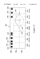
- FIG. 6B illustrates color-space distance of a scanned pixel of the foreground image from the origin of the KAB color-space co-ordinate system shown in FIG. 6 A.
- the color of the scanned pixel is represented by the point 610 .
- This point lies at a distance 611 from the origin 605 and has color components, x, y and z respectively.
- the distance 611 is given by Pythagoras's theorem in three-dimensions, equation 612 .
- the distance 611 is given by the square root of the sum of the squares of the color distance components.
- this equation that is used for calculating distances in color-space relative to a transformed origin.
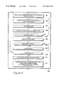
- Procedure 704 for the identification of a base color representing the background of the foreground image is detailed in FIG. 8 .
- the video artist selects background color points using a color picker or stylus 102 on a touch tablet 103 .
- the selected points, specified as RGB components are stored in a buffer.
- processor 101 obtains the next point stored in the buffer.
- the point selected at step 803 is processed so as to form part of a 3-D convex hull.
- a 3-D convex hull is the smallest convex surface that contains a given set of points.
- a set of points is convex if for any two points in the set, the points on a straight line segment joining the two points are also contained within the set.
Abstract
Description
Claims (18)
Applications Claiming Priority (4)
| Application Number | Priority Date | Filing Date | Title |
|---|---|---|---|
| GBGB9619119.2A GB9619119D0 (en) | 1996-09-12 | 1996-09-12 | Processing image |
| GB9619119.2 | 1996-09-12 | ||
| GB9619119 | 1996-09-12 | ||
| PCT/IB1997/001104 WO1998011510A1 (en) | 1996-09-12 | 1997-09-12 | Processing image data |
Publications (2)
| Publication Number | Publication Date |
|---|---|
| US20020025066A1 US20020025066A1 (en) | 2002-02-28 |
| US6445816B1 true US6445816B1 (en) | 2002-09-03 |
Family
ID=10799868
Family Applications (1)
| Application Number | Title | Priority Date | Filing Date |
|---|---|---|---|
| US09/068,421 Expired - Lifetime US6445816B1 (en) | 1996-09-12 | 1997-09-12 | Compositing video image data |
Country Status (5)
| Country | Link |
|---|---|
| US (1) | US6445816B1 (en) |
| EP (1) | EP0873552A1 (en) |
| CA (1) | CA2237265A1 (en) |
| GB (1) | GB9619119D0 (en) |
| WO (1) | WO1998011510A1 (en) |
Cited By (45)
| Publication number | Priority date | Publication date | Assignee | Title |
|---|---|---|---|---|
| US20020080379A1 (en) * | 2000-07-18 | 2002-06-27 | Yasuharu Iwaki | Image processing device and method |
| US20020150307A1 (en) * | 1999-04-26 | 2002-10-17 | Adobe Systems Incorporated, A Delaware Corporation | Smart erasure brush |
| US20020164071A1 (en) * | 2001-03-14 | 2002-11-07 | Imagica Corp. | Color conversion method and apparatus for chromakey processing |
| US20020191204A1 (en) * | 2001-06-07 | 2002-12-19 | Noriyuki Nishi | Picture image processing apparatus and method, and picture processing system |
| US20030206665A1 (en) * | 2002-05-04 | 2003-11-06 | Autodesk Canada Inc. | Processing image data |
| US20030206587A1 (en) * | 2002-05-01 | 2003-11-06 | Cristina Gomila | Chroma deblocking filter |
| US20030219151A1 (en) * | 2002-05-21 | 2003-11-27 | Curry Bo U. | Method and system for measuring a molecular array background signal from a continuous background region of specified size |
| US6721453B1 (en) * | 2000-07-10 | 2004-04-13 | The Board Of Trustees Of The University Of Illinois | Method and apparatus for processing an image of an agricultural field |
| US20040109014A1 (en) * | 2002-12-05 | 2004-06-10 | Rovion Llc | Method and system for displaying superimposed non-rectangular motion-video images in a windows user interface environment |
| US20040131249A1 (en) * | 2001-05-04 | 2004-07-08 | Barry Sandrew | Image sequence enhancement system and method |
| US20050212820A1 (en) * | 2004-03-26 | 2005-09-29 | Ross Video Limited | Method, system, and device for automatic determination of nominal backing color and a range thereof |
| US20050231511A1 (en) * | 2004-04-16 | 2005-10-20 | Frank Doepke | User definable transition tool |
| US20060109903A1 (en) * | 2004-03-15 | 2006-05-25 | James Bergen | Method and apparatus for providing noise reduction |
| US20070247679A1 (en) * | 2006-04-21 | 2007-10-25 | Daniel Pettigrew | Workflows for color correcting images |
| US20070247475A1 (en) * | 2006-04-21 | 2007-10-25 | Daniel Pettigrew | 3D histogram and other user interface elements for color correcting images |
| US20070247647A1 (en) * | 2006-04-21 | 2007-10-25 | Daniel Pettigrew | 3D lut techniques for color correcting images |
| US20080056614A1 (en) * | 2002-01-04 | 2008-03-06 | Warner Bros. Entertainment Inc. | Registration of separations |
| US20080089609A1 (en) * | 2002-01-04 | 2008-04-17 | Warner Bros. Entertainment Inc. | Image Registration System |
| US20080165397A1 (en) * | 2007-01-04 | 2008-07-10 | Novatek Microelectronics Corp. | Method and apparatus of color conversion |
| US20090167843A1 (en) * | 2006-06-08 | 2009-07-02 | Izzat Hekmat Izzat | Two pass approach to three dimensional Reconstruction |
| US20090284554A1 (en) * | 2005-12-21 | 2009-11-19 | Ingo Tobias Doser | Constrained Color Palette in a Color Space |
| US20100177959A1 (en) * | 2006-01-27 | 2010-07-15 | Lockheed Martin Corporation | Color form dropout using dynamic geometric solid thresholding |
| US7835570B1 (en) | 2002-01-04 | 2010-11-16 | Warner Bros. Entertainment Inc. | Reducing differential resolution of separations |
| US20110038536A1 (en) * | 2009-08-14 | 2011-02-17 | Genesis Group Inc. | Real-time image and video matting |
| US7907793B1 (en) | 2001-05-04 | 2011-03-15 | Legend Films Inc. | Image sequence depth enhancement system and method |
| US8160390B1 (en) | 1970-01-21 | 2012-04-17 | Legend3D, Inc. | Minimal artifact image sequence depth enhancement system and method |
| US20120287300A1 (en) * | 2000-02-11 | 2012-11-15 | Sony Electronics Inc. | Masking tool |
| US8385684B2 (en) | 2001-05-04 | 2013-02-26 | Legend3D, Inc. | System and method for minimal iteration workflow for image sequence depth enhancement |
| US8730232B2 (en) | 2011-02-01 | 2014-05-20 | Legend3D, Inc. | Director-style based 2D to 3D movie conversion system and method |
| US8897596B1 (en) | 2001-05-04 | 2014-11-25 | Legend3D, Inc. | System and method for rapid image sequence depth enhancement with translucent elements |
| US8994744B2 (en) | 2004-11-01 | 2015-03-31 | Thomson Licensing | Method and system for mastering and distributing enhanced color space content |
| US9007365B2 (en) | 2012-11-27 | 2015-04-14 | Legend3D, Inc. | Line depth augmentation system and method for conversion of 2D images to 3D images |
| US9007404B2 (en) | 2013-03-15 | 2015-04-14 | Legend3D, Inc. | Tilt-based look around effect image enhancement method |
| US9031383B2 (en) | 2001-05-04 | 2015-05-12 | Legend3D, Inc. | Motion picture project management system |
| US9113130B2 (en) | 2012-02-06 | 2015-08-18 | Legend3D, Inc. | Multi-stage production pipeline system |
| US9241147B2 (en) | 2013-05-01 | 2016-01-19 | Legend3D, Inc. | External depth map transformation method for conversion of two-dimensional images to stereoscopic images |
| US9241128B2 (en) | 2013-02-14 | 2016-01-19 | Warner Bros. Entertainment Inc. | Video conversion technology |
| US9282321B2 (en) | 2011-02-17 | 2016-03-08 | Legend3D, Inc. | 3D model multi-reviewer system |
| US9288476B2 (en) | 2011-02-17 | 2016-03-15 | Legend3D, Inc. | System and method for real-time depth modification of stereo images of a virtual reality environment |
| US9286941B2 (en) | 2001-05-04 | 2016-03-15 | Legend3D, Inc. | Image sequence enhancement and motion picture project management system |
| US9407904B2 (en) | 2013-05-01 | 2016-08-02 | Legend3D, Inc. | Method for creating 3D virtual reality from 2D images |
| US9438878B2 (en) | 2013-05-01 | 2016-09-06 | Legend3D, Inc. | Method of converting 2D video to 3D video using 3D object models |
| US9547937B2 (en) | 2012-11-30 | 2017-01-17 | Legend3D, Inc. | Three-dimensional annotation system and method |
| US9609307B1 (en) | 2015-09-17 | 2017-03-28 | Legend3D, Inc. | Method of converting 2D video to 3D video using machine learning |
| US20200184733A1 (en) * | 2016-06-17 | 2020-06-11 | Imagination Technologies Limited | Generating an Augmented Reality Image Using a Blending Factor |
Families Citing this family (37)
| Publication number | Priority date | Publication date | Assignee | Title |
|---|---|---|---|---|
| GB9619119D0 (en) | 1996-09-12 | 1996-10-23 | Discreet Logic Inc | Processing image |
| US6128001A (en) * | 1997-04-04 | 2000-10-03 | Avid Technology, Inc. | Methods and apparatus for changing a color of an image |
| GB9806322D0 (en) * | 1998-03-26 | 1998-05-20 | Rolls Royce Plc | Interpretation of thermal paint |
| GB2336055B (en) | 1998-04-01 | 2002-10-16 | Discreet Logic Inc | Image processing |
| GB2336054B (en) * | 1998-04-01 | 2002-10-16 | Discreet Logic Inc | Processing image data |
| GB2336056B (en) * | 1998-04-01 | 2002-10-16 | Discreet Logic Inc | Image processing |
| GB9807097D0 (en) | 1998-04-02 | 1998-06-03 | Discreet Logic Inc | Processing image data |
| US7417640B1 (en) | 1999-01-29 | 2008-08-26 | Lg Electronics Inc. | Method for dominant color setting of video region and data structure and method of confidence measure extraction |
| US6456300B1 (en) | 1999-03-31 | 2002-09-24 | Autodesk Canada Inc. | Method and apparatus for processing image data to produce control data |
| US6553140B1 (en) * | 1999-04-16 | 2003-04-22 | Avid Technology, Inc. | Method and system for spill correction |
| WO2000064189A2 (en) * | 1999-04-16 | 2000-10-26 | Avid Technology, Inc. | Safe color limiting of a color on a digital nonlinear editing system |
| US6657646B2 (en) * | 1999-06-08 | 2003-12-02 | Amx Corporation | System and method for multimedia display |
| GB0007974D0 (en) | 2000-04-01 | 2000-05-17 | Discreet Logic Inc | Processing image data |
| JP3642258B2 (en) * | 2000-05-08 | 2005-04-27 | 松下電器産業株式会社 | Video composition device |
| AU2001292946A1 (en) * | 2000-09-26 | 2002-04-08 | Advantage 3D Llc | Method and system for generation, storage and distribution of omni-directional object views |
| KR20050005531A (en) * | 2002-06-03 | 2005-01-13 | 코닌클리케 필립스 일렉트로닉스 엔.브이. | Encoding and decoding of watermarks in independent channels |
| GB2400257A (en) * | 2003-04-05 | 2004-10-06 | Autodesk Canada Inc | Removal of grain |
| DE102004008223A1 (en) * | 2004-02-19 | 2005-09-15 | Henkel Kgaa | A method and apparatus for determining a target hair color for a source hair color of a hair area in a digital image after hair color change |
| US7262780B2 (en) * | 2004-08-23 | 2007-08-28 | Micron Technology, Inc. | Simple and robust color saturation adjustment for digital images |
| US9063739B2 (en) | 2005-09-07 | 2015-06-23 | Open Invention Network, Llc | Method and computer program for device configuration |
| JP2008205871A (en) * | 2007-02-21 | 2008-09-04 | Megachips Lsi Solutions Inc | Imaging unit, portable terminal device, and portable terminal system |
| US8264468B1 (en) | 2007-06-19 | 2012-09-11 | Imaging Systems Technology, Inc. | Touch system for blue screen |
| US8330730B1 (en) | 2007-09-04 | 2012-12-11 | Imaging Systems Technology, Inc. | Calibrating of interactive touch system for image compositing |
| US8817125B2 (en) * | 2009-06-25 | 2014-08-26 | Koninklijke Philips N.V. | Gesture recognition using chroma-keying |
| JP2011109245A (en) * | 2009-11-13 | 2011-06-02 | Renesas Electronics Corp | Image processor and image processing method |
| US8649592B2 (en) | 2010-08-30 | 2014-02-11 | University Of Illinois At Urbana-Champaign | System for background subtraction with 3D camera |
| US8553978B2 (en) | 2010-11-03 | 2013-10-08 | Csr Technology Inc. | System and method for providing multi resolution purple fringing detection and correction |
| US8823726B2 (en) * | 2011-02-16 | 2014-09-02 | Apple Inc. | Color balance |
| US9485433B2 (en) | 2013-12-31 | 2016-11-01 | Personify, Inc. | Systems and methods for iterative adjustment of video-capture settings based on identified persona |
| EP3032497A3 (en) * | 2014-12-09 | 2016-06-29 | Thomson Licensing | Method and apparatus for color correction |
| US9916668B2 (en) | 2015-05-19 | 2018-03-13 | Personify, Inc. | Methods and systems for identifying background in video data using geometric primitives |
| US9563962B2 (en) | 2015-05-19 | 2017-02-07 | Personify, Inc. | Methods and systems for assigning pixels distance-cost values using a flood fill technique |
| CA3013926A1 (en) * | 2016-02-08 | 2017-08-17 | Imago Systems, Inc. | System and method for the visualization and characterization of objects in images |
| US9883155B2 (en) * | 2016-06-14 | 2018-01-30 | Personify, Inc. | Methods and systems for combining foreground video and background video using chromatic matching |
| CN106408632B (en) * | 2016-09-08 | 2019-10-25 | 广州阿里巴巴文学信息技术有限公司 | A kind of tone variations cartoon implementing method and device based on attribute animation |
| US9881207B1 (en) | 2016-10-25 | 2018-01-30 | Personify, Inc. | Methods and systems for real-time user extraction using deep learning networks |
| US20220405987A1 (en) * | 2021-06-18 | 2022-12-22 | Nvidia Corporation | Pixel blending for neural network-based image generation |
Citations (21)
| Publication number | Priority date | Publication date | Assignee | Title |
|---|---|---|---|---|
| US4864388A (en) | 1983-03-28 | 1989-09-05 | Ole Skrydstrup | Chroma keyer color discriminator |
| US4908874A (en) * | 1980-04-11 | 1990-03-13 | Ampex Corporation | System for spatially transforming images |
| US5105469A (en) * | 1990-02-05 | 1992-04-14 | Crosfield Electronics Limited | Control data array generation apparatus and method |
| FR2681967A1 (en) | 1991-10-01 | 1993-04-02 | Electronics For Imaging Inc | Process and apparatus for modifying the colours of an image with the aid of a computer |
| US5218432A (en) * | 1992-01-02 | 1993-06-08 | Tandy Corporation | Method and apparatus for merging video data signals from multiple sources and multimedia system incorporating same |
| US5268754A (en) * | 1991-03-01 | 1993-12-07 | Barco Graphics N.V. | Method and a device for converting a color coordinate set |
| US5301016A (en) | 1991-12-21 | 1994-04-05 | U.S. Philips Corporation | Method of and arrangement for deriving a control signal for inserting a background signal into parts of a foreground signal |
| US5347622A (en) | 1991-04-12 | 1994-09-13 | Accom Inc. | Digital image compositing system and method |
| US5455633A (en) | 1992-09-03 | 1995-10-03 | U.S. Philips Corporation | Chromakey method for processing picture signals in which fading operations are performed in proportional zones based on a control signal |
| US5497431A (en) * | 1992-11-18 | 1996-03-05 | Fuji Photo Film Co., Ltd. | Method of extracting characteristic image data and color data conversion device for image processing apparatus |
| EP0735511A2 (en) | 1995-03-29 | 1996-10-02 | Dainippon Screen Mfg. Co., Ltd. | Method and apparatus for changing specified color in a color image |
| US5585944A (en) * | 1994-05-10 | 1996-12-17 | Kaleida Labs, Inc. | Method for compressing and decompressing images by subdividing pixel color distributions |
| US5630037A (en) * | 1994-05-18 | 1997-05-13 | Schindler Imaging, Inc. | Method and apparatus for extracting and treating digital images for seamless compositing |
| US5696839A (en) * | 1993-04-08 | 1997-12-09 | Linotype-Hell Ag | Method and apparatus for reproducing an image employing a transformation of color solids |
| WO1998011510A1 (en) | 1996-09-12 | 1998-03-19 | Discreet Logic Inc. | Processing image data |
| US5812214A (en) * | 1996-03-14 | 1998-09-22 | Sierra Video Systems, Inc. | Apparatus and method for compositing video images |
| US5812694A (en) * | 1995-09-15 | 1998-09-22 | Agfa-Gevaert N.V. | Color separation method and apparatus for same |
| US5850472A (en) * | 1995-09-22 | 1998-12-15 | Color And Appearance Technology, Inc. | Colorimetric imaging system for measuring color and appearance |
| US5852673A (en) * | 1996-03-27 | 1998-12-22 | Chroma Graphics, Inc. | Method for general image manipulation and composition |
| US5982924A (en) * | 1996-08-02 | 1999-11-09 | University Of Washington | Method and system for reproducing color images as duotones |
| US6128046A (en) * | 1995-05-12 | 2000-10-03 | Sony Corporation | Key signal generating apparatus and picture synthesis apparatus, and key signal generating method and picture synthesis method |
-
1996
- 1996-09-12 GB GBGB9619119.2A patent/GB9619119D0/en active Pending
-
1997
- 1997-09-12 US US09/068,421 patent/US6445816B1/en not_active Expired - Lifetime
- 1997-09-12 CA CA002237265A patent/CA2237265A1/en not_active Abandoned
- 1997-09-12 WO PCT/IB1997/001104 patent/WO1998011510A1/en not_active Application Discontinuation
- 1997-09-12 EP EP97939109A patent/EP0873552A1/en not_active Ceased
Patent Citations (21)
| Publication number | Priority date | Publication date | Assignee | Title |
|---|---|---|---|---|
| US4908874A (en) * | 1980-04-11 | 1990-03-13 | Ampex Corporation | System for spatially transforming images |
| US4864388A (en) | 1983-03-28 | 1989-09-05 | Ole Skrydstrup | Chroma keyer color discriminator |
| US5105469A (en) * | 1990-02-05 | 1992-04-14 | Crosfield Electronics Limited | Control data array generation apparatus and method |
| US5268754A (en) * | 1991-03-01 | 1993-12-07 | Barco Graphics N.V. | Method and a device for converting a color coordinate set |
| US5347622A (en) | 1991-04-12 | 1994-09-13 | Accom Inc. | Digital image compositing system and method |
| FR2681967A1 (en) | 1991-10-01 | 1993-04-02 | Electronics For Imaging Inc | Process and apparatus for modifying the colours of an image with the aid of a computer |
| US5301016A (en) | 1991-12-21 | 1994-04-05 | U.S. Philips Corporation | Method of and arrangement for deriving a control signal for inserting a background signal into parts of a foreground signal |
| US5218432A (en) * | 1992-01-02 | 1993-06-08 | Tandy Corporation | Method and apparatus for merging video data signals from multiple sources and multimedia system incorporating same |
| US5455633A (en) | 1992-09-03 | 1995-10-03 | U.S. Philips Corporation | Chromakey method for processing picture signals in which fading operations are performed in proportional zones based on a control signal |
| US5497431A (en) * | 1992-11-18 | 1996-03-05 | Fuji Photo Film Co., Ltd. | Method of extracting characteristic image data and color data conversion device for image processing apparatus |
| US5696839A (en) * | 1993-04-08 | 1997-12-09 | Linotype-Hell Ag | Method and apparatus for reproducing an image employing a transformation of color solids |
| US5585944A (en) * | 1994-05-10 | 1996-12-17 | Kaleida Labs, Inc. | Method for compressing and decompressing images by subdividing pixel color distributions |
| US5630037A (en) * | 1994-05-18 | 1997-05-13 | Schindler Imaging, Inc. | Method and apparatus for extracting and treating digital images for seamless compositing |
| EP0735511A2 (en) | 1995-03-29 | 1996-10-02 | Dainippon Screen Mfg. Co., Ltd. | Method and apparatus for changing specified color in a color image |
| US6128046A (en) * | 1995-05-12 | 2000-10-03 | Sony Corporation | Key signal generating apparatus and picture synthesis apparatus, and key signal generating method and picture synthesis method |
| US5812694A (en) * | 1995-09-15 | 1998-09-22 | Agfa-Gevaert N.V. | Color separation method and apparatus for same |
| US5850472A (en) * | 1995-09-22 | 1998-12-15 | Color And Appearance Technology, Inc. | Colorimetric imaging system for measuring color and appearance |
| US5812214A (en) * | 1996-03-14 | 1998-09-22 | Sierra Video Systems, Inc. | Apparatus and method for compositing video images |
| US5852673A (en) * | 1996-03-27 | 1998-12-22 | Chroma Graphics, Inc. | Method for general image manipulation and composition |
| US5982924A (en) * | 1996-08-02 | 1999-11-09 | University Of Washington | Method and system for reproducing color images as duotones |
| WO1998011510A1 (en) | 1996-09-12 | 1998-03-19 | Discreet Logic Inc. | Processing image data |
Non-Patent Citations (2)
| Title |
|---|
| Glassner, Andrew S., Book: "Principles of Digital Image Synthesis", Chapter 2: "2.1 Perceptually Uniform Color Spaces: L*u*v* and L*a*b*", vol. 1, 1-69, 1995. |
| Poirson, Allen B. & Wandell, Brian A.: "Pattern-color separable pathways predict sensitivity to simple colored patterns," Dept. of Psychology, Stanford University, Stanford, CA 94305, Vision Research, Feb. 1996, pp. 1-27. |
Cited By (104)
| Publication number | Priority date | Publication date | Assignee | Title |
|---|---|---|---|---|
| US8160390B1 (en) | 1970-01-21 | 2012-04-17 | Legend3D, Inc. | Minimal artifact image sequence depth enhancement system and method |
| US6791573B2 (en) * | 1999-04-26 | 2004-09-14 | Adobe Systems Incorporated | Smart erasure brush |
| US20080317388A1 (en) * | 1999-04-26 | 2008-12-25 | Adobe Systems Incorporated | Smart Erasure Brush |
| US20050074165A1 (en) * | 1999-04-26 | 2005-04-07 | Adobe Systems Incorporated, A Delaware Corporation | Smart erasure brush |
| US7400763B2 (en) | 1999-04-26 | 2008-07-15 | Adobe Systems Incorporated | Smart erasure brush |
| US7627168B2 (en) | 1999-04-26 | 2009-12-01 | Adobe Systems Incorporated | Smart erasure brush |
| US20020150307A1 (en) * | 1999-04-26 | 2002-10-17 | Adobe Systems Incorporated, A Delaware Corporation | Smart erasure brush |
| US20120287300A1 (en) * | 2000-02-11 | 2012-11-15 | Sony Electronics Inc. | Masking tool |
| US9224191B2 (en) | 2000-02-11 | 2015-12-29 | Sony Corporation | Masking tool |
| US9418401B2 (en) | 2000-02-11 | 2016-08-16 | Sony Corporation | Masking tool |
| US8755631B2 (en) | 2000-02-11 | 2014-06-17 | Sony Corporation | Masking tool |
| US8750644B2 (en) * | 2000-02-11 | 2014-06-10 | Sony Corporation | Masking tool |
| US6721453B1 (en) * | 2000-07-10 | 2004-04-13 | The Board Of Trustees Of The University Of Illinois | Method and apparatus for processing an image of an agricultural field |
| US7292370B2 (en) * | 2000-07-18 | 2007-11-06 | Fujifilm Corporation | Image processing device and method |
| US20020080379A1 (en) * | 2000-07-18 | 2002-06-27 | Yasuharu Iwaki | Image processing device and method |
| US7092122B2 (en) * | 2000-07-18 | 2006-08-15 | Fuji Photo Film Co., Ltd. | Image processing device and method |
| US20050259286A1 (en) * | 2000-07-18 | 2005-11-24 | Yasuharu Iwaki | Image processing device and method |
| US20020164071A1 (en) * | 2001-03-14 | 2002-11-07 | Imagica Corp. | Color conversion method and apparatus for chromakey processing |
| US6807296B2 (en) * | 2001-03-14 | 2004-10-19 | Imagica Corp. | Color conversion method and apparatus for chromakey processing |
| US8897596B1 (en) | 2001-05-04 | 2014-11-25 | Legend3D, Inc. | System and method for rapid image sequence depth enhancement with translucent elements |
| US20040131249A1 (en) * | 2001-05-04 | 2004-07-08 | Barry Sandrew | Image sequence enhancement system and method |
| US8953905B2 (en) | 2001-05-04 | 2015-02-10 | Legend3D, Inc. | Rapid workflow system and method for image sequence depth enhancement |
| US7181081B2 (en) * | 2001-05-04 | 2007-02-20 | Legend Films Inc. | Image sequence enhancement system and method |
| US9615082B2 (en) * | 2001-05-04 | 2017-04-04 | Legend3D, Inc. | Image sequence enhancement and motion picture project management system and method |
| US9031383B2 (en) | 2001-05-04 | 2015-05-12 | Legend3D, Inc. | Motion picture project management system |
| US8401336B2 (en) | 2001-05-04 | 2013-03-19 | Legend3D, Inc. | System and method for rapid image sequence depth enhancement with augmented computer-generated elements |
| US8396328B2 (en) | 2001-05-04 | 2013-03-12 | Legend3D, Inc. | Minimal artifact image sequence depth enhancement system and method |
| US8385684B2 (en) | 2001-05-04 | 2013-02-26 | Legend3D, Inc. | System and method for minimal iteration workflow for image sequence depth enhancement |
| US20060171584A1 (en) * | 2001-05-04 | 2006-08-03 | Sandrew Barry B | Image sequence enhancement system and method |
| US9286941B2 (en) | 2001-05-04 | 2016-03-15 | Legend3D, Inc. | Image sequence enhancement and motion picture project management system |
| US7333670B2 (en) * | 2001-05-04 | 2008-02-19 | Legend Films, Inc. | Image sequence enhancement system and method |
| US20160198142A1 (en) * | 2001-05-04 | 2016-07-07 | Legend3D, Inc. | Image sequence enhancement and motion picture project management system |
| US8078006B1 (en) | 2001-05-04 | 2011-12-13 | Legend3D, Inc. | Minimal artifact image sequence depth enhancement system and method |
| US8073247B1 (en) | 2001-05-04 | 2011-12-06 | Legend3D, Inc. | Minimal artifact image sequence depth enhancement system and method |
| US7907793B1 (en) | 2001-05-04 | 2011-03-15 | Legend Films Inc. | Image sequence depth enhancement system and method |
| US7221476B2 (en) * | 2001-06-07 | 2007-05-22 | Noritsu Koki Co., Ltd. | Picture image processing apparatus and method, and picture processing system |
| US20020191204A1 (en) * | 2001-06-07 | 2002-12-19 | Noriyuki Nishi | Picture image processing apparatus and method, and picture processing system |
| US9104938B2 (en) | 2002-01-04 | 2015-08-11 | Warner Bros. Entertainment Inc. | Registration of separations |
| US7835570B1 (en) | 2002-01-04 | 2010-11-16 | Warner Bros. Entertainment Inc. | Reducing differential resolution of separations |
| US9773314B2 (en) | 2002-01-04 | 2017-09-26 | Warner Bros. Entertainment Inc. | Registration of separations |
| US8094972B2 (en) | 2002-01-04 | 2012-01-10 | Warner Bros. Entertainment Inc. | Registration of separations |
| US7486842B2 (en) * | 2002-01-04 | 2009-02-03 | Warner Bros. Entertainment Inc. | Registration of separations |
| US7672541B2 (en) | 2002-01-04 | 2010-03-02 | Warner Bros. Entertainment Inc. | Registration of separations |
| US20080089609A1 (en) * | 2002-01-04 | 2008-04-17 | Warner Bros. Entertainment Inc. | Image Registration System |
| US20080137979A1 (en) * | 2002-01-04 | 2008-06-12 | Warner Bros. Entertainment Inc. | Registration of separations |
| US7715655B2 (en) | 2002-01-04 | 2010-05-11 | Warner Bros. Entertainment Inc. | Image registration system |
| US20100150469A1 (en) * | 2002-01-04 | 2010-06-17 | Warner Bros. Entertainment Inc. | Registration of Separations |
| US8818088B2 (en) | 2002-01-04 | 2014-08-26 | Warner Bros. Entertainment Inc. | Registration of separations |
| US8401337B2 (en) | 2002-01-04 | 2013-03-19 | Warner Bros. Entertainment Inc. | Registration of separations |
| US20080056614A1 (en) * | 2002-01-04 | 2008-03-06 | Warner Bros. Entertainment Inc. | Registration of separations |
| WO2003094497A3 (en) * | 2002-05-01 | 2004-02-05 | Thomson Licensing Sa | Chroma deblocking filter |
| KR100988984B1 (en) | 2002-05-01 | 2010-10-20 | 톰슨 라이센싱 | Chroma deblocking filter |
| WO2003094497A2 (en) * | 2002-05-01 | 2003-11-13 | Thomson Licensing S.A. | Chroma deblocking filter |
| US20030206587A1 (en) * | 2002-05-01 | 2003-11-06 | Cristina Gomila | Chroma deblocking filter |
| US7319415B2 (en) * | 2002-05-01 | 2008-01-15 | Thomson Licensing | Chroma deblocking filter |
| US7072510B2 (en) * | 2002-05-04 | 2006-07-04 | Autodesk Canada Co. | Adjusting data representing image pixel color |
| US20030206665A1 (en) * | 2002-05-04 | 2003-11-06 | Autodesk Canada Inc. | Processing image data |
| US20030219151A1 (en) * | 2002-05-21 | 2003-11-27 | Curry Bo U. | Method and system for measuring a molecular array background signal from a continuous background region of specified size |
| US7221785B2 (en) * | 2002-05-21 | 2007-05-22 | Agilent Technologies, Inc. | Method and system for measuring a molecular array background signal from a continuous background region of specified size |
| US20040109014A1 (en) * | 2002-12-05 | 2004-06-10 | Rovion Llc | Method and system for displaying superimposed non-rectangular motion-video images in a windows user interface environment |
| US7702178B2 (en) * | 2004-03-15 | 2010-04-20 | Sarnoff Corporation | Method and apparatus for providing noise reduction |
| US20060109903A1 (en) * | 2004-03-15 | 2006-05-25 | James Bergen | Method and apparatus for providing noise reduction |
| US7508455B2 (en) | 2004-03-26 | 2009-03-24 | Ross Video/Live Production Technology | Method, system, and device for automatic determination of nominal backing color and a range thereof |
| US20050212820A1 (en) * | 2004-03-26 | 2005-09-29 | Ross Video Limited | Method, system, and device for automatic determination of nominal backing color and a range thereof |
| US8205154B2 (en) * | 2004-04-16 | 2012-06-19 | Apple Inc. | User definable transition tool |
| US20050231511A1 (en) * | 2004-04-16 | 2005-10-20 | Frank Doepke | User definable transition tool |
| US8994744B2 (en) | 2004-11-01 | 2015-03-31 | Thomson Licensing | Method and system for mastering and distributing enhanced color space content |
| US9219898B2 (en) | 2005-12-21 | 2015-12-22 | Thomson Licensing | Constrained color palette in a color space |
| US20090284554A1 (en) * | 2005-12-21 | 2009-11-19 | Ingo Tobias Doser | Constrained Color Palette in a Color Space |
| US7961941B2 (en) * | 2006-01-27 | 2011-06-14 | Lockheed Martin Corporation | Color form dropout using dynamic geometric solid thresholding |
| US20100177959A1 (en) * | 2006-01-27 | 2010-07-15 | Lockheed Martin Corporation | Color form dropout using dynamic geometric solid thresholding |
| US8022964B2 (en) | 2006-04-21 | 2011-09-20 | Apple Inc. | 3D histogram and other user interface elements for color correcting images |
| US20070247679A1 (en) * | 2006-04-21 | 2007-10-25 | Daniel Pettigrew | Workflows for color correcting images |
| US20070247475A1 (en) * | 2006-04-21 | 2007-10-25 | Daniel Pettigrew | 3D histogram and other user interface elements for color correcting images |
| US20070247647A1 (en) * | 2006-04-21 | 2007-10-25 | Daniel Pettigrew | 3D lut techniques for color correcting images |
| US7693341B2 (en) | 2006-04-21 | 2010-04-06 | Apple Inc. | Workflows for color correcting images |
| US20100188415A1 (en) * | 2006-04-21 | 2010-07-29 | Apple Inc. | Workflows for Color Correcting Images |
| US8203571B2 (en) | 2006-04-21 | 2012-06-19 | Apple Inc. | 3D histogram for color images |
| US8031962B2 (en) | 2006-04-21 | 2011-10-04 | Apple Inc. | Workflows for color correcting images |
| US20090167843A1 (en) * | 2006-06-08 | 2009-07-02 | Izzat Hekmat Izzat | Two pass approach to three dimensional Reconstruction |
| US20080165397A1 (en) * | 2007-01-04 | 2008-07-10 | Novatek Microelectronics Corp. | Method and apparatus of color conversion |
| US7813003B2 (en) * | 2007-01-04 | 2010-10-12 | Novatek Microelectronics Corp. | Method and apparatus of color conversion |
| US20110038536A1 (en) * | 2009-08-14 | 2011-02-17 | Genesis Group Inc. | Real-time image and video matting |
| US8320666B2 (en) * | 2009-08-14 | 2012-11-27 | Genesis Group Inc. | Real-time image and video matting |
| US8730232B2 (en) | 2011-02-01 | 2014-05-20 | Legend3D, Inc. | Director-style based 2D to 3D movie conversion system and method |
| US9288476B2 (en) | 2011-02-17 | 2016-03-15 | Legend3D, Inc. | System and method for real-time depth modification of stereo images of a virtual reality environment |
| US9282321B2 (en) | 2011-02-17 | 2016-03-08 | Legend3D, Inc. | 3D model multi-reviewer system |
| US9443555B2 (en) | 2012-02-06 | 2016-09-13 | Legend3D, Inc. | Multi-stage production pipeline system |
| US9113130B2 (en) | 2012-02-06 | 2015-08-18 | Legend3D, Inc. | Multi-stage production pipeline system |
| US9270965B2 (en) | 2012-02-06 | 2016-02-23 | Legend 3D, Inc. | Multi-stage production pipeline system |
| US9007365B2 (en) | 2012-11-27 | 2015-04-14 | Legend3D, Inc. | Line depth augmentation system and method for conversion of 2D images to 3D images |
| US9547937B2 (en) | 2012-11-30 | 2017-01-17 | Legend3D, Inc. | Three-dimensional annotation system and method |
| US9723257B2 (en) | 2013-02-14 | 2017-08-01 | Warner Bros. Entertainment Inc. | Video conversion technology |
| US10687017B2 (en) | 2013-02-14 | 2020-06-16 | Warner Bros. Entertainment Inc. | Video conversion technology |
| US9241128B2 (en) | 2013-02-14 | 2016-01-19 | Warner Bros. Entertainment Inc. | Video conversion technology |
| US10277862B2 (en) | 2013-02-14 | 2019-04-30 | Warner Bros. Entertainment Inc. | Video conversion technology |
| US9007404B2 (en) | 2013-03-15 | 2015-04-14 | Legend3D, Inc. | Tilt-based look around effect image enhancement method |
| US9438878B2 (en) | 2013-05-01 | 2016-09-06 | Legend3D, Inc. | Method of converting 2D video to 3D video using 3D object models |
| US9241147B2 (en) | 2013-05-01 | 2016-01-19 | Legend3D, Inc. | External depth map transformation method for conversion of two-dimensional images to stereoscopic images |
| US9407904B2 (en) | 2013-05-01 | 2016-08-02 | Legend3D, Inc. | Method for creating 3D virtual reality from 2D images |
| US9609307B1 (en) | 2015-09-17 | 2017-03-28 | Legend3D, Inc. | Method of converting 2D video to 3D video using machine learning |
| US20200184733A1 (en) * | 2016-06-17 | 2020-06-11 | Imagination Technologies Limited | Generating an Augmented Reality Image Using a Blending Factor |
| US11087554B2 (en) * | 2016-06-17 | 2021-08-10 | Imagination Technologies Limited | Generating an augmented reality image using a blending factor |
| US11830153B2 (en) | 2016-06-17 | 2023-11-28 | Imagination Technologies Limited | Generating an augmented reality image using a blending factor |
Also Published As
| Publication number | Publication date |
|---|---|
| GB9619119D0 (en) | 1996-10-23 |
| US20020025066A1 (en) | 2002-02-28 |
| CA2237265A1 (en) | 1998-03-19 |
| EP0873552A1 (en) | 1998-10-28 |
| WO1998011510A1 (en) | 1998-03-19 |
Similar Documents
| Publication | Publication Date | Title |
|---|---|---|
| US6445816B1 (en) | Compositing video image data | |
| EP0947956B1 (en) | Primary and secondary color manipulations using hue, saturation, luminance and area isolation | |
| US6496599B1 (en) | Facilitating the compositing of video images | |
| US4984072A (en) | System and method for color image enhancement | |
| US7215813B2 (en) | Method and apparatus for color correction | |
| US6751347B2 (en) | Color diamond chroma keying | |
| US5204665A (en) | Color editing with simple encoded images | |
| US5105469A (en) | Control data array generation apparatus and method | |
| US5077610A (en) | Previewing cuts and transformations in an electronic image composition system | |
| EP0302454B1 (en) | System and method for color image enhancement | |
| US6571012B1 (en) | Adjusting a softness region | |
| CA2326996A1 (en) | Method and apparatus for color manipulation | |
| US5487020A (en) | Refinement of color images using reference colors | |
| JPH06225329A (en) | Method and device for chromakey processing | |
| JPH1023267A (en) | Sharpness-processing unit for image | |
| US20030234810A1 (en) | Graphical user interface for color correction using curves | |
| GB2312120A (en) | Producing a transition region surrounding an image | |
| US6456300B1 (en) | Method and apparatus for processing image data to produce control data | |
| US20020171764A1 (en) | Electronic image keying systems | |
| Naiman | Color spaces and color contrast | |
| US6295369B1 (en) | Multi-dimensional color image mapping apparatus and method | |
| Kalra | GamOpt: A tool for visualization and optimization of gamuts | |
| JP3027620B2 (en) | Color editing method using simple coded images | |
| US6052109A (en) | Processing image data | |
| KR20000010958A (en) | Color correction device, color correction method, picture processing device, and picture processing method |
Legal Events
| Date | Code | Title | Description |
|---|---|---|---|
| AS | Assignment |
Owner name: DISCREET LOGIC INC, CANADA Free format text: ASSIGNMENT OF ASSIGNORS INTEREST;ASSIGNOR:PETTIGREW, DANIEL;REEL/FRAME:009606/0149 Effective date: 19980610 Owner name: DISCREET LOGIC (UK) LIMITED, ENGLAND Free format text: ASSIGNMENT OF ASSIGNORS INTEREST;ASSIGNOR:PETTIGREW, DANIEL;REEL/FRAME:009606/0149 Effective date: 19980610 |
|
| AS | Assignment |
Owner name: AUTODESK LIMITED, ENGLAND Free format text: ASSIGNMENT OF ASSIGNORS INTEREST;ASSIGNOR:DISCREET LOGIC (UK) LIMITED;REEL/FRAME:012107/0339 Effective date: 20010814 Owner name: DISCREET LOGIC INC., CANADA Free format text: ASSIGNMENT OF ASSIGNORS INTEREST;ASSIGNOR:AUTODESK LIMITED;REEL/FRAME:012107/0351 Effective date: 20010814 |
|
| AS | Assignment |
Owner name: AUTODESK CANADA INC., CANADA Free format text: CHANGE OF NAME;ASSIGNOR:DISCREET LOGIC INC.;REEL/FRAME:012897/0077 Effective date: 20020201 |
|
| STCF | Information on status: patent grant |
Free format text: PATENTED CASE |
|
| CC | Certificate of correction | ||
| AS | Assignment |
Owner name: AUTODESK CANADA CO.,CANADA Free format text: ASSIGNMENT OF ASSIGNORS INTEREST;ASSIGNOR:AUTODESK CANADA INC.;REEL/FRAME:016641/0922 Effective date: 20050811 Owner name: AUTODESK CANADA CO., CANADA Free format text: ASSIGNMENT OF ASSIGNORS INTEREST;ASSIGNOR:AUTODESK CANADA INC.;REEL/FRAME:016641/0922 Effective date: 20050811 |
|
| FPAY | Fee payment |
Year of fee payment: 4 |
|
| AS | Assignment |
Owner name: AUTODESK, INC., CALIFORNIA Free format text: ASSIGNMENT OF ASSIGNORS INTEREST;ASSIGNOR:AUTODESK CANADA CO.;REEL/FRAME:022445/0222 Effective date: 20090225 Owner name: AUTODESK, INC.,CALIFORNIA Free format text: ASSIGNMENT OF ASSIGNORS INTEREST;ASSIGNOR:AUTODESK CANADA CO.;REEL/FRAME:022445/0222 Effective date: 20090225 |
|
| FPAY | Fee payment |
Year of fee payment: 8 |
|
| SULP | Surcharge for late payment |
Year of fee payment: 7 |
|
| REMI | Maintenance fee reminder mailed | ||
| FPAY | Fee payment |
Year of fee payment: 12 |
|
| SULP | Surcharge for late payment |
Year of fee payment: 11 |