US6452809B1 - Scalable internet engine - Google Patents
Scalable internet engine Download PDFInfo
- Publication number
- US6452809B1 US6452809B1 US09/709,820 US70982000A US6452809B1 US 6452809 B1 US6452809 B1 US 6452809B1 US 70982000 A US70982000 A US 70982000A US 6452809 B1 US6452809 B1 US 6452809B1
- Authority
- US
- United States
- Prior art keywords
- engine
- chassis
- connector
- cabinet
- motherboard
- Prior art date
- Legal status (The legal status is an assumption and is not a legal conclusion. Google has not performed a legal analysis and makes no representation as to the accuracy of the status listed.)
- Expired - Lifetime
Links
Images


Classifications
-
- G—PHYSICS
- G06—COMPUTING; CALCULATING OR COUNTING
- G06F—ELECTRIC DIGITAL DATA PROCESSING
- G06F1/00—Details not covered by groups G06F3/00 - G06F13/00 and G06F21/00
- G06F1/16—Constructional details or arrangements
Definitions
- the present invention is related to a co-pending application filed concurrently herewith and entitled “Method and System For Providing Dynamic Hosted Service Management Across Disparate Accounts/Sites,” a copy of which is attached hereto and the disclosure of which is hereby incorporated by reference.
- the present invention relates generally to the field of computer processing systems. More specifically, the present invention relates to a scalable server engine comprised of a large number of commercially available server boards each arranged as an engine blade in a power and space efficient chassis.
- ISPs Internet Service Providers
- ASPs Application Service Providers
- ISVs Independent Software Vendors
- ESPs Enterprise Solution Providers
- MSPs Managed Service Providers
- HSPs Hosted Service Providers
- a server can be a personal computer that is connected to the Internet through a network interface and that runs specific software designed to service the requests made by customers or clients of that server.
- HSPs For all of the various delivery models that can be used by HSPs to provide hosted services, most HSPs will use a collection of servers that are connected to an internal network in what is commonly referred to as a “server farm”, with each server performing unique tasks or the group of servers sharing the load of multiple tasks, such as mail server, web server, access server, accounting and management server.
- server farm In the context of hosting websites, for example, customers with smaller websites are often aggregated onto and supported by a single web server. Larger websites, however, are commonly hosted on dedicated web servers that provide services solely for that site.
- ISP survival Guide Strategies For Running A Competitive ISP, (1999).
- HSPs have preferred to utilize server farms consisting of large numbers of individual personal computer servers wired to a common Internet connection or bank of modems and sometimes accessing a common set of disk drives.
- server farms consisting of large numbers of individual personal computer servers wired to a common Internet connection or bank of modems and sometimes accessing a common set of disk drives.
- the HSP deploys only that level of hardware required to support its current customer level. Equally as important, the HSP can charge its customers an upfront setup fee that covers a significant portion of the cost of this hardware. By utilizing this approach, the HSP does not have to spend money in advance for large computer systems with idle capacity that will not generate immediate revenue for the HSP.
- the server farm solution also affords an easier solution to the problem of maintaining security and data integrity across different customers than if those customers were all being serviced from a single larger mainframe computer. If all of the servers for a customer are loaded only with the software for that customer and are connected only to the data for that customer, security of that customer's information is insured by physical isolation.
- HSPs As HSPs increased their capacity, the number of servers in their computer room or data center also increased. To conserve on floor space in the computer room or data center, an HSP would install rack mounted cabinets to allow multiple servers to be stacked together on the same amount of floor space. Individual personal computer servers could then be stacked either vertically or horizontally in these rack mounted cabinets together with switching equipment and modems.
- servers As a further improvement on the conventional power packaging enclosure of a typical personal computer server, servers have been developed specifically for rack mounting in what are referred to as “pizza box” or “U” formats where each server slides horizontally into one or more slots in a rack mounted cabinet. Examples of homogeneous servers packaged in this type of a rack mounted configuration include the RaQ server line from Cobalt Network Systems, the Netfinity server line from IBM and the A-class server line from Hewlett-Packard.
- rack mounted servers offer a considerable improvement in terms of space efficiency as compared to conventional tower cabinet personal computer servers, installing or adding new rack mounted servers to a server farm continues to be a manual operation involving significant amounts of cabling and wire connection, as well as software and network configuration.
- the rack-mounted server is designed as an independent computer system, each server is provided with its own power supply. In order to keep the overall cost of the servers reasonable, these individual power supplies are inexpensive and therefore relatively inefficient.
- a server farm consisting of several rack-mounted servers consumes a large amount of electricity and dissipates a large quantity of waste heat. This problem is particularly acute in the thinnest 1U form factor that would allow for the greatest number of servers to be stacked on top of each other. Because each of the 1U servers is positioned horizontally in the rack cabinet, air flow within the cabinet is severely restricted and the height of the 1 U servers prevents the use of a large enough fan to overcome these air flow restrictions.
- Chatterbox server line from ChatCom, Inc.
- the chassis for the Chatterbox system supported a number of front-loading, hot-swappable modules, including server motherboards, power supplies and RAID drives.
- specially designed server motherboards were slid into a chassis in a vertical orientation, as compared to the horizontal orientation of the motherboards for rack-mounted servers.
- the motherboards modules also were designed to accommodate different versions of the early Intel processors as the main CPU, and included a monitored COM port to which a modem was connected and a microcontroller and associated software that monitored the modem and managed the connection of the I/O port to the main CPU on the motherboard.
- the main CPU was an Intel or Intel compatible 386, 486, Pentium or Pentium Pro processor.
- the motherboard was either a proprietary design of ChatCom or a generic AT style board available from one of the early PC motherboard manufacturers. Power could be distributed directly from the hot swappable power supplies in the chassis to the motherboard for these early servers because, unlike current generation servers that use standard ATX power supplies with integrated power management and control, these early servers had no power management and control systems incorporated into the standard circuitry for the motherboard.
- the Chatterbox server line allowed for more convenient access to the hot-swappable modules, cabling connections for the modem and network cards had to be routed along the back edge of the hot-pluggable unit and har to be removed prior to removal of the unit.
- the network and modem cards are inserted in connector slots such that they are oriented perpendicular to the surface of the motherboard.
- these cards had to be positioned parallel to the surface of the motherboard in order to allow the motherboard module to fit vertically into the chassis. This made accessing the cabling connections difficult as the motherboard module needed to be removed from the chassis in order to make any cabling changes.
- U.S. Pat. No. 5,877,938 a packaging system for a server provides for hot swappable disk drives and power supply modules and uses a horizontal tray compartment at the top of the chassis to contain the server motherboards stacked in a horizontal orientation in the slide out tray.
- U.S. Pat. No. 6,025,989 a modular arrangement for a rack mounted computer processor is described in which the disk drive, fan, motherboard and power supply are arranged in side-by-side sub modules within a rack mounted horizontally oriented housing.
- Packaging arrangements for other types of multiple computer processor systems have sought to solve some of the problems of locating and accessing multiple components in a cabinet by using a midplane arrangement that effectively divides the circuitry for each component into a front processor portion and a rear I/O portion that are separated by a midplane.
- U.S. Pat. No. 5,251,097 describes a supercomputer packaging architecture with orthogonal midplanes where the I/O portion is connected at the front to the midplane and at the rear to a backplane.
- U.S. Pat. No. 5,488,541 describes a VME backplane arrangement with a connectorized midplane to connect multiple processors together.
- U.S. Pat. No. 5,912,802 describes a midplane telecommunication switch cabinet that houses multiple telephony switching components.
- U.S. Pat. Nos. 6,035,356 and 6,094,351 a cross-platform architecture for tower-type personal computers uses two boards in place of a conventional single motherboard.
- the first board is a processor board and the second board is the I/O board.
- the boards are oriented in a vertical position and arranged within an elongated housing in an offset end-to-end parallel orientation and connected by a pair of connectors. In this way different motherboards can be connected to a common design for the I/O board through the pair of connectors.
- U.S. Pat. No. 6,094,351 two different kinds of removable backpanels are used to accommodate different types of motherboards in a common tower-type cabinet.
- the present invention is a scalable Internet engine comprised of a large number of commercially available server boards each arranged as an engine blade in a power and space efficient cabinet.
- the engine blades are removably positioned in a front side of the cabinet in a vertical orientation.
- a through plane in the middle of a chassis assembly within the cabinet provides common power and control peripheral signals to all engine blades. I/O signals for each engine blade are routed through apertures in the through plane to interface cards positioned in the rear of the cabinet.
- the scalable engine can accommodate different types of server boards in the same chassis assembly because of a common blade carrier structure. Different types of commercially available motherboards are mounted in the common blade carrier structure that provides a uniform mechanical interface to the chassis assembly.
- a specially designed PCI host board that can plug into various types of motherboards has a first connector for connecting to the through plane and second connector for connecting to the interface cards. Redundant hot-swappable high-efficiency power supplies are connected to the common power signals on the through plane.
- the host board includes management circuitry that distributes the power signals to the server board for that engine blade by emulating the ATX power management protocol.
- Replaceable fan trays are mounted below the engine blades to cool the engine.
- the cabinet accommodates multiple rows of engine blades each in a sub-chassis that are stacked on top of each other, as well as rack mounted networks switches and disk drives.
- the scalable engine of the present invention has numerous advantages over the designs of existing servers. Unlike existing homogenous server configurations that rely on similar server boards from the same manufacturer, the scalable Internet engine supports many different types of commercially available server boards that can all be mounted in the same uniform chassis. This allows an HSP to utilize different server boards for different applications within the same chassis. It also enables the use of state-of-the-art ATX motherboards as soon as these boards are available, and takes advantage of the reduced costs and increased reliability of mass-produced, commodity ATX motherboards.
- the unique through plane arrangement allows for true hot swappable capabilities for both the engine blades and the interface cards. Individual engine blades can be removed and replaced without the need to unplug interface cards or network cabling. This eliminates one of the highest points of failure in maintaining any computer system, namely problems caused by the disconnection and reconnection of I/O cables. Connections for all of the data paths are isolated to protect against data faults during removal or insertion of an engine blade.
- a passive I/O backplane is interposed between the second connector of the host board and the interface card on the rear side of the through plane. The I/O backplane routes the PCI signals to allow for side-by-side installation of two or more interface cards per engine blade.
- the scalable engine allows for multi-level fault tolerance and redundancy to be implemented across all components in a highly effective manner.
- engines blades can be assigned from one customer to another customer easily and automatically without the need for manual intervention. This enables the dynamic allocation of blades in response to changing customer requirements and allows the HSP to make use of excess server resources that otherwise would be statically assigned to a single customer domain.
- Redundant engine blades can be assigned to a particular customer and quickly and automatically brought online in the event of an engine blade failure.
- the power supplies preferably are highly efficient and triple redundant (N+2). Similarly, the use of multiple fan trays provides for redundant cooling protection for each row of engine blades. Maintenance requirements are greatly simplified by the overall design of the scalable engine.
- a single cabinet engine can support up to 32 engine blades.
- This scalable engine provides the same server capacity as conventional 2U rack mounted servers in half the floor space with savings of 75 percent in both power and air-conditioning requirements.
- the management circuitry associated with each engine blade allows for efficient management and control of the scalable engine outside of the I/O network of the server engine.
- This circuitry reports status and error conditions, controls power up and power down operations by emulating the standard ATX power management protocol and communicates with an agent executing on the processor in the motherboard.
- All of the engine blades can be connected to and controlled from a single console and keyboard, even when multiple cabinets are arranged in the side-by-side configuration.
- Common peripheral devices such as a keyboard, video, mouse, diskette drive, can be selectively switched by the system operator to any of the engine blades.
- FIG. 1 is an exploded perspective view of one embodiment of a single cabinet scalable engine with skins and doors.
- FIG. 2 is a front view of another embodiment of the scalable engine with four cabinets in a side-by-side arrangement.
- FIG. 3 is a top view sectional view of a chassis assembly for the scalable engine.
- FIG. 4 is an exploded perspective view of the detail of two cabinets for the scalable engine in a side-by-side arrangement.
- FIGS. 5, 6 and 7 are a top, side and perspective view of the fan tray.
- FIGS. 8 and 9 are front and rear cutaway perspective views of the redundant power supplies.
- FIG. 10 is an exploded perspective view of the detail of a door for the scalable engine.
- FIGS. 11-14 are exploded assembly views of the various assembly steps for an engine blade.
- FIG. 15 is an exploded assembly view of the through plane.
- FIG. 16 is a front view of an assembled through plane.
- FIG. 17 is a perspective view of a shared peripheral connector for the rear of the power system.
- FIGS. 18, 19 and 20 are top, side and perspective views of a typical I/O backplane.
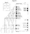
- FIGS. 21-31 are schematic diagrams of a preferred embodiment of the host board of the present invention.
- FIG. 1 an overview of a scalable engine 100 in accordance with a preferred embodiment the present invention will now be described.
- a server 100 housed in a single cabinet 110 will be described first, although it will be recognized that the scalability of the server of the present invention allows for a very large number of cabinets 110 to be configured together as a single engine server 100 .
- the cabinet 110 has a front side 112 , a rear side 114 , a left side 116 and a right side 118 .
- each of the left side 116 and right side 118 has a corresponding side panel or skin 120 rigidly mounted to the cabinet 110 with screws, bolts or similar fastening mechanisms 121 that preferably connect to a bracket 122 in each comer of the frame 110 .
- the side panels 120 could be welded onto the cabinet 110 so as to form an integral assembly.
- one or both of side panels 120 may be absent depending upon the position of the cabinet 110 within an overall side-by-side arrangement.
- At least the front side 112 is provided with a door panel 124 attached to the front side 112 by hinges 125 .
- the rear side 114 may be provided with a similar door panel 124 .
- the door panel 124 is latched and preferably lockable to the cabinet 110 by a latch bar 126 .
- other forms of attaching and securing door panel 124 to the front side 112 or rear side 114 could be utilized, such as sliding attachment, hanging attachment, or removable attachment.
- a panel 127 may be installed on either or both of the top and bottom of the cabinet 110 , depending upon structural, cooling and electrical isolation requirements.
- the cabinet 110 is a 19′′ NEBS compliant metal rack that is 19′′ wide, 1000 mm deep and up to 84′′ tall.
- the cabinet 110 is preferably constructed of metal.
- the side panels 120 and door panels 124 may be metal, fiberglass or plastic depending upon weight, cost and electrical isolation considerations.
- the NEBS compliant cabinet of the present invention meets applicable NEBS standards for airflow, dust, shock and vibration limits for cabinetry housing electrical equipment.
- a through plane 130 separates the front side 112 from the rear side 114 in that portion of the cabinet 110 that houses a plurality of engine blades 132 and a plurality of interface cards 134 .
- Each engine blade 132 contains at least one processor and each interface card 134 manages at least one input/output (I/O) communication channel for the associated processor with either disk storage (e.g., an array of SCSI disks, a Storage Array Network (SAN) unit or a Fibre Channel (FC) disk array) or communication switches (e.g., FC switches, ATM switches, Ethernet switches or modems).
- disk storage e.g., an array of SCSI disks, a Storage Array Network (SAN) unit or a Fibre Channel (FC) disk array
- communication switches e.g., FC switches, ATM switches, Ethernet switches or modems.
- the front door panel 124 allows access to the engine blades 132 from the front side 112 and the rear door panel 124 (if present) allows access to the interface cards 134 from the rear side 114 .
- Cabling (not shown) for interconnecting the interface cards 134 with the associated disk storage or communication switching equipment is conveniently accessible from the rear side 114 without the need for disturbing the engine blades 132 on the front side 112 .
- engine blades 132 can be replaced without any need for disconnecting or otherwise disturbing the interface cards 134 or the cabling connected to those cards.
- each chassis assembly 128 can be arranged in a stacked fashion within a single cabinet 110 , with each chassis assembly 128 providing space for up to sixteen (16) engine blades 132 .
- each chassis assembly 128 includes two sub-chassis 129 arranged one on top of the other and each providing space for up to eight (8) engine blades per sub-chassis 129 .
- a power frame 144 as will be described is mounted below the pair of sub-chassis 129 to form the completed chassis assembly 128 .
- a total of thirty-two engine blades 132 may be housed in a single cabinet 110 .
- the preferred embodiment is described with respect to a pair of sub-chassis 129 and a pair of chassis assemblies 128 per cabinet, it will be understood that other arrangements of the numbers of engine blades 132 , sub-chassis 129 and chassis 128 is contemplated by the present invention. It will also be understood that while the preferred embodiment of the invention is described in terms of an outer cabinet 110 having multiple chassis assemblies 128 positioned therein, any type of chassis arrangement involving a frame, cabinet or housing for configuring the engine blades 132 in accordance with the present invention is intended to be within the scope of the present invention.
- the engine blades 132 of the present invention are positioned vertically within each sub-chassis 129 .
- additional components can also be housed in the chassis 110 .
- each fan tray 140 has a plurality of individual fan units 142 such that a single fan unit 142 can fail and the fan tray can still create sufficient air movement to adequately cool the engine blades 132 .
- a plug-in power connection 143 is provided at a rear of each fan tray 140 .
- the fan trays 140 are secured in the sub-chassis 128 by hand-operated oversized screws 141 or other forms of latching means.
- a plurality of power supplies 144 are removably housed in a frame 146 that is mounted in the chassis assembly 128 separately from the sub-chassis 129 .
- the power frame 146 includes an AC/DC board 148 that coordinates power supplied from the power supplies 144 and routes this power to the through plane 130 .
- at least three (3) removable power supplies 144 are installed in the power frame 146 , even though only two (2) would be required to power a fully populated cabinet 110 . This feature provides for redundancy in the event of a failure of any one of the power supplies 144 .
- Up to four (4) power supplies 144 are slidably mounted on the power frame 146 via tracks 170 .
- the power supplies 144 in a preferred embodiment are high efficiency 400 watt multiple power output power supplies, such as the HP3 available from Magnetec.
- Connectors 172 on the front side of the AC/DC board 148 attach to connectors 174 on the rear of the power supplies to allow the power supplies to be hot swappable.
- Standard peripheral connectors 176 for plug-in CD drives or hard drives are provided on the front side of portion 178 of the AC/DC board 148 .
- a set of shared peripheral connections 179 are mounted on the rear of the AC/DC board 148 .
- the shared peripheral connections 179 preferably provide similar functionality as the direct peripheral connections 304 shown in FIG. 15 . It is preferred that electronic quick switches be used to isolate the peripherals from each blade 132 and connect them to one blade 132 at a time when a select button is pressed for that blade 132 .
- the AC/DC board 148 also includes connections for common peripheral devices, such as a CD drive 150 and a boot disk drive 152 . External connections for other common peripheral devices, such as a common control console having a keyboard, mouse and display (not shown) are also provided, either on the AC/DC board 148 or on the through plane 130 .
- common peripheral devices such as a CD drive 150 and a boot disk drive 152 .
- external connections for other common peripheral devices such as a common control console having a keyboard, mouse and display (not shown) are also provided, either on the AC/DC board 148 or on the through plane 130 .
- each chassis assembly 128 including two sub-chassis 129 , a power frame 146 and a row of fan trays 140 , is approximately 37′′ high. In an alternate embodiment adapted to accommodate quad processor servers, the chassis assembly 128 is approximately 40′′ high. In another embodiment as shown in FIG. 1, each chassis assembly 128 holds up to eight (8) engine blades 132 in a single sub-chassis 129 , with space at the bottom of each sub-chassis 129 for the fan trays 140 and the power frame 146 .
- Rack mounted switching equipment 154 such as a Fibre Channel switch or a cross point circuit switch, also can be housed in the cabinet 110 .
- the depth of cabinet 110 and the ability to access cabinet 110 from both the front and rear allows for two standard 1 U switches to be mounted front and rear in a single slot within the cabinet.
- one or more of the chassis assemblies 128 can be replaced by rack mounted disk storage units 156 . Again, the depth and the ability to access cabinet 110 from both the front and rear allows for a potential doubling up of individual disk storage units 156 in the same slot, depending upon the depth of such units.
- chassis 110 may be housed within chassis 110 as long as such components support rack mounting, either directly or with the use of a sub-frame.
- peripheral components such as alternative kinds of storage devices, different kinds of switching equipment, modems or the like, and different common peripherals like floppy disks or tape drives, may be housed within chassis 110 as long as such components support rack mounting, either directly or with the use of a sub-frame.
- a scalable engine 102 comprising multiple cabinets 110 will be described.
- two or more cabinets 110 are combined together to form one scalable engine 102 .
- at least one of the side panels 120 of each cabinet 110 is removed to allow secure bolting of frames together and provide convenient access of cabling between adjacent cabinets 110 when the cabinets 110 are positioned in a side-by-side arrangement.
- a side-by-side arrangement is the more efficient in terms of floor space usage, it should be understood that multiple cabinets 110 may be cabled together with each cabinet arranged in a freestanding manner.
- two or more rows of cabinets 110 may be considered as part of a single engine 102 .
- one or more circles or partial circles of cabinets 110 may be created as a configuration for a single engine 102 where, for example, the cabinets with engine blades 132 are arranged in an outer circle with the front door panels 124 facing outward and the DASD, SAN and Network cabinets are arranged in the center of the outer circle
- up to 1024 engine blades 132 can be organized as part of a single scalable engine 102 comprised of four rows of sixteen cabinets 110 which also includes up to 16 terrabytes of rack mounted disk storage.
- up to 1,000 cabinets 110 could be configured as a single scalable engine 100 providing as many as 100,000 servers.
- the size of a single scalable engine 102 will be a function of available floor space and is not necessarily limited by the technology utilized to implement the scalable engine 102 . Practically, it is anticipated that the size of a single scalable engine 102 will be limited to a manageable number of cabinets 110 that can be arranged in a given computer room environment.
- the side-by-side arrangement of the cabinets 110 is supplemented with a separation structure 160 between adjacent cabinets 110 that affords easier access for cabling and an air passage for cooling.
- the separation structure 160 preferably is also designed to enhance the aesthetic appearance of the server 102 .
- the structure 160 includes a top plate 161 , removable rear plates 162 , a pair of mounting brackets 163 , structure 164 defining a light box and a light bar lens 165 .
- the light box structure 164 is wired to accommodate a pair of fluorescent bulbs (not shown) to illuminate the light bar lens 165 .
- FIG. 10 shows a preferred embodiment of the front door panel 124 .
- An extruded hinge piece 180 is attached to one side of a panel 181 .
- the panel 181 is slightly curved and is perforated to allow for air flow and to enable viewing of indicators on the engine blades 132 as shown in FIG. 2 . The perforations also add to the distinctive appearance of the door panel 124 .
- a top plate 182 and bottom plate 183 are attached to the panel 181 and provide further support structure.
- An extruded latch piece 184 is attached to the other side of the panel 181 .
- a plate latch 185 is secured to the cabinet 110 and preferably includes springs 186 to provide a tolerance and give to a latching arrangement that includes a bracket 187 and knob 188 .
- a logo or unit identifier can be attached as shown at 189 .
- Each engine blade 132 includes a motherboard 200 mounted in a common blade carrier structure 202 that provides a uniform mechanical interface to the cabinet 110 .
- the blade carrier structure 202 is removably positioned in the front side 112 of the cabinet 110 .
- a group of connectors 204 are positioned along a rear edge of the engine blade 132 . At least a first portion of these connectors 206 , 207 will operably mate with an interface card connector 136 (FIG. 16) on an interface card 134 .
- a second portion of these connectors 208 , 209 will mate with through plane connectors 300 , 302 (FIG. 15 ).
- the common blade carrier structure 202 is arranged to accommodate a planar surface of a motherboard 200 in a generally vertical orientation and is sufficiently oversized to accommodate the largest motherboard 200 with additional space reserved toward the front of the blade carrier structure 202 to accommodate an internal hard drive or other local peripheral device if desired.
- the blade carrier structure 202 has dimensions of 16.5′′ long by 12′′ high.
- the blade carrier structure has dimensions of 16.5′′ long by 13.75′′ high.
- each motherboard 200 is a commercially available motherboard that includes at least one PCI connector 205 .
- Each engine blade 132 includes a host board 210 connected to the PCI connector 205 and oriented with a planar surface of the host board 210 generally parallel to the planar surface of the motherboard 200 .
- the host board 210 provides the group of connectors 204 on a rear edge of the host board 210 .
- the use of a specially designed host board 210 with a standard PCI connection allows the engine blade 132 to accommodate a number of different commercially available motherboards 200 in the blade carrier structure 202 without requiring any modification to the motherboard so long as all of the different motherboards 200 have dimensions of their planar surface that are capable of being mounted in the blade carrier structure 202 .
- Examples of commercially available motherboards 200 that can be used with the engine blade 132 of the present invention include Pentium® motherboards, Sparc® motherboards and Alpha® motherboards. This feature allows a single engine 100 to accommodate a first engine blade 132 that has a first type of motherboard 200 with a first type of processor and a second engine blade 132 that has a second type of motherboard 200 with a second type of processor that is different than the first type of motherboard 200 and first type of processor in the same cabinet 110 , or even in the same chassis assembly 128 .
- the first type of engine blade 132 is optimized as a front-end server that hosts Web applications interfacing with consumers to respond to inquiries.
- the second type of engine blade 132 is a database blade optimized to search and mine the information warehouse of a customer.
- a third type of engine blade 132 is optimized to serve video streaming and graphic imaging. Any of these three types of engine blades 132 could utilize any type of motherboard, but the flexibility of the present invention allows for best-of-breed technology to be used for a given application without requiring that all of the technology be provided by a single manufacturer or run a single operating system, for example.
- the present invention is intended to accommodate changes in the design of the busses, the host board and the I/O backplane as newer standards and technology evolve for these components as well.
- the blade carrier structure 202 includes a base plate 220 having a front edge 222 , a rear edge 224 and a pair of side edges 226 , 228 .
- a pair of supports 230 are operably attached to each side of the base plate proximate the rear edge 224 of the base plate 220 , preferably by screws or the like.
- the supports 230 define a width of the blade carrier structure 202 that is larger than a distance between the planar surfaces of the motherboard 200 and the host board 210 and extends to a distance that is higher than a highest one of the components mounted on the host board 210 .
- a front plate 232 is operably attached at one side along the front edge 222 of the base plate 220 , preferably by screws or the like.
- the front plate 232 has a width substantially equal to the width of the blade carrier structure 202 as defined by the supports 230 .
- a pair of rails 234 , 236 are operably attached at a front end to the front plate 232 and at a rear end to one of the pair of supports 230 , preferably by screws or the like.
- a projection defined along the pair of side edges 234 , 236 is adapted to mate with a pair of tracks 235 (FIG. 3) in the sub-chassis 129 to provide the uniform mechanical interface to the cabinet 110 .
- the base plate 220 is preferably metal that is grounded to the cabinet 110 to serve as an isolation for electrical interference.
- An insulation sheet 242 is positioned between the base plate 220 and the motherboard 200 and oriented parallel to the planar surfaces of the motherboard 200 and the host board 210 .
- the host board 210 is supported by standoffs 244 and a pair of projections 246 .
- a cross member 248 provides additional dimensional stability to the rear of the blade carrier structure 202 .
- the face plate 232 is provided with a series of indicator lights and actuator buttons in a control/status panel 250 that extend through a decorative cover plate 252 .
- a latch assembly 254 uses a latch 256 to cooperate with a projection below the bottom track in the sub-chassis 128 to urge the connectors 204 into mechanical and electrical connection with their corresponding mating connectors and removably secure the engine blade 132 in the sub-chassis 129 .
- Wires (not shown) connect the control/status panel 250 to connectors on the host board 210 .
- the through plane 130 is mounted in the sub-chassis 129 between the front side 112 and the rear side 116 .
- a separate through plane 130 is provided for each sub-chassis 129 with wire connections between provided as required between adjoining through planes 130 in the same chassis assembly 128 or cabinet 110 .
- a single through plane 130 could be provided for the entire cabinet 110 as an alternative, or that separate through planes 130 could be provided for each chassis assembly 128 .
- At least two through plane connectors 300 , 302 are provided for each engine blade 132 that is housed in the sub-chassis 129 that mate with the second portion 208 , 209 of the group of connectors 204 on the rear edge of the host board 210 .
- the connector 300 includes connections for power that is delivered to the through plane 130 from the AC/DC board 148 and mates with connector 208 .
- the connector 302 includes connections for the control peripheral signals common to each of the plurality of engine blades and mates with the connector 209 .
- the connector 302 includes a set of switched connections that enable the engine blades 132 to share common peripherals such as console or boot drives and a second set of unswitched connections that allow an operator to directly connect a dedicated peripheral to a particular engine blade 132 .
- FIG. 15 shows a set of dedicated peripheral connections 304 that are mounted on the rear of the through plane 130 and allow for direct access to the peripheral connections of a particular engine blade 132 from the rear side 114 of the cabinet 110 .
- connectors 300 , 302 and 304 can be unmounted and new connectors attached by having the connectors screwed onto the through plane 130 , for example.
- At least one aperture 306 is defined in the through plane 130 corresponding to each of the through plane connectors 300 , 302 .
- the apertures 306 permit the first portion 206 , 207 of the group of connectors 204 on the rear edge of the host board 210 to be accessed from the rear side of the sub-chassis 128 .
- This first portion 206 of the group of connectors 204 include connections for I/O signals to operably connect to the corresponding interface card 134 for that engine blade 132 . It is preferably one or more high density signal connectors such as available from AMP.
- this is accomplished via a separate I/O backplane 310 that allows the interface card 134 to remain plugged into the rear side of the I/O backplane 310 when the engine blade 134 is removed and a portion 207 of the group of connectors 204 provides power to the I/O backplane 310 .
- the interface cards 134 could be housed in a mechanical housing which secures the interface cards 134 in place within the cabinet 110 such that engine blades 132 could be directly plugged into the interface cards 134 . This embodiment, however, does not as easily allow for the advantages of doubling up interface cards 134 per engine blade 132 . There are also issues with respect to the routing of the I/O signals through the I/O backplane 310 that have other advantages.
- the through plane 130 is mechanically attached by screws, welds or similar mechanisms to a metal midplane sub-frame 320 which also contains apertures 312 corresponding to apertures 310 .
- the midplane sub-frame 320 is mechanically attached to the sub-chassis 129 within the chassis assembly 128 .
- the through plane 132 and midplane sub-frame 320 preferably allow for the support and connection of the fan trays 140 via electrical power connections 330 and control and sensor connections 332 .
- the I/O backplane 310 provides one connector 312 that connects with the first portion 206 of the group of connectors 204 on the host board 210 .
- Some number of standard PCI connectors 314 , 316 on the rear side of the I/O backplane 310 provide plug-in connections for a similar number of separate standard interface cards 134 .
- a separate power connector 318 is provided on the front side of the I/O backplane 310 that extends through an upper portion of the aperture 306 in the through plane 130 to connect to a power connector 207 on the host board. In this way, either the engine blade 132 or interface card 134 can be disconnected from power by the power management circuitry on the host board without the need to interrupt power supplied to the other.
- the generic PCI signals minus all side band signals (signals which make each PCI slot unique) are routed up the PCI riser from the mother board 200 and across the host board 210 .
- Each PCI slot's side-band signals are also routed using low profile plug boards straight across the host board 210 as well. These lines are basically equal length and routing them is fairly straightforward until the signals reach the high density connector 206 at the rear edge of the host board 210 .
- the placement of the pins on the host board 210 that connect to the high density connector 206 must be chosen to insure equal lengths of the PCI signals with respect to their destination on the PCI connectors 314 and 316 .
- the routing of the side band signals is done such that the PCI slot furthest from the host board 210 will be routed closest to the high density connector 206 and so on until the PCI slot closest to the host board 210 is routed to the furthest pins on the high density connector 206 .
- ISA bus signals are routed next to the PCI signals and over the through plane 130 to the I/O backplane 310 .
- I/O backplanes that are designed for only a single aperture 306
- the host board and I/O backplane may use a PCI bridge such that a single PCI slot on the motherboard can be used to generate as many PCI signals on the I/O backplane as a necessary, regardless of the number of PCI slots on the motherboard.
- each engine blade 132 is comprised of multiple processors, or even multiple motherboards per engine blade, while still maintaining the advantages of the common blade carrier structure and the through plane as described.
- FIGS. 21-31 the schematic details of a preferred embodiment of the connectors 204 , host board 210 and I/O backplane 310 will be presented.
- FIG. 21 shows an overview of the signal routing among the management processor 260 on the host board 210 , the motherboard PCI connector 205 and the backplane signal connector 209 .
- FIGS. 22 and 23 show the detailed signal routing of the PCI bus signal and other signals to the I/O backplane 310 via connector 306 consistent with the principals previously described for how the PCI signals need to be routed.
- FIG. 24 shows the detailed routing of how the PCI signals are picked up from the mother board 200 via connector 205 .
- FIG. 21 shows an overview of the signal routing among the management processor 260 on the host board 210 , the motherboard PCI connector 205 and the backplane signal connector 209 .
- FIGS. 22 and 23 show the detailed signal routing of the PCI bus signal and other signals to the I/O backplane 310 via connector 306 consistent with the principals previously described
- FIG. 25 shows an overview of the routing of the peripheral signals from the motherboard 200 to the host board 210 and onto the connector 209 .
- FIG. 26 shows the details of how these peripheral signals are switched to implement the shared peripheral I/O arrangement as previously described.
- FIGS. 27 and 28 show the details of how the peripheral signals are routed from the motherboard 200 to the host board 210 and onto the connector 209 .
- FIG. 31 shows the preferred embodiment of the management bus interface.
- FIG. 29 shows the schematic details of the management processor 260 .
- Flash memory 262 stores the power up sequences and configuration information to be utilized by the management processor 260 in the manner as described more fully in the previously identified co-pending application entitled “Method and System For Providing Dynamic Hosted Service Management Across Disparate Accounts/Sites.”
- the power up sequences, configuration information and other control channel information are communicated to the host management processor over a an out-of-band communication channel referred to as a management bus that is managed by a management bus interface 264 on the host board 210 .
- Voltage sense information is collected by circuitry 266 and routed to the front panel connector 267 for display along with other status information.
- a switch 268 allows for manual selection of the motherboard 200 and host board 210 for control of the shared peripheral signals.
- Slot identifier 269 produces a unique signal for each engine blade 132 in a sub-chassis 128 .
- FIG. 30 shows the schematic details of how the power levels are sensed for circuitry 266 and also the details for the ATX power connections 270 .
- the ATX power connections 270 emulate the ATX power up sequence that is normally present for an ATX motherboard 200 .
- this power up sequence is stored in the flash memory 262 to allow the power up sequence to be altered in the event of changes in the protocol or standard for the ATX form factor motherboards 200 .
- the design takes advantage of the protocol handshake between each motherboard and its associated ATX power supply, such that the microprocessor on the host board can use the standard ATX power-up sequence of communications to communicate with its associated motherboard, while still allowing industry standard management software, such as LANsite, to communicate with the motherboard as well.
- the time period is preferably established by delaying a fixed time value multiplied by a slot identifier value has generated by the slot identifier 269 .
- the fixed time value is selected to allow the spikes and transients associated with powering on the motherboard 200 to settle out sufficiently before the next motherboard 200 is brought online.
- each host board 210 can be programmed to wait until it receives a power-up request from the management network 264 or from a manual invocation of the front panel power switch 268 for that engine blades 132 before applying power to the motherboard 200 .
Abstract
Description
Claims (15)
Priority Applications (10)
| Application Number | Priority Date | Filing Date | Title |
|---|---|---|---|
| US09/709,820 US6452809B1 (en) | 2000-11-10 | 2000-11-10 | Scalable internet engine |
| CA002415769A CA2415769C (en) | 2000-07-17 | 2001-06-28 | Scalable internet engine |
| CNB018127932A CN1264078C (en) | 2000-07-17 | 2001-06-28 | High expandable internet super server |
| AT01950589T ATE520292T1 (en) | 2000-07-17 | 2001-06-28 | SCALABLE INTERNET ENGINE |
| JP2002513247A JP2004519750A (en) | 2000-07-17 | 2001-06-28 | Scalable internet engine |
| KR1020037000791A KR100859760B1 (en) | 2000-07-17 | 2001-06-28 | Scalable internet engine |
| PCT/US2001/020570 WO2002007488A1 (en) | 2000-07-17 | 2001-06-28 | Scalable internet engine |
| EP01950589A EP1317876B1 (en) | 2000-07-17 | 2001-06-28 | Scalable internet engine |
| AU2001271563A AU2001271563A1 (en) | 2000-07-17 | 2001-06-28 | Scalable internet engine |
| US10/244,450 US6606253B2 (en) | 2000-11-10 | 2002-09-16 | Scalable internet engine |
Applications Claiming Priority (1)
| Application Number | Priority Date | Filing Date | Title |
|---|---|---|---|
| US09/709,820 US6452809B1 (en) | 2000-11-10 | 2000-11-10 | Scalable internet engine |
Related Child Applications (1)
| Application Number | Title | Priority Date | Filing Date |
|---|---|---|---|
| US10/244,450 Continuation US6606253B2 (en) | 2000-11-10 | 2002-09-16 | Scalable internet engine |
Publications (1)
| Publication Number | Publication Date |
|---|---|
| US6452809B1 true US6452809B1 (en) | 2002-09-17 |
Family
ID=24851425
Family Applications (2)
| Application Number | Title | Priority Date | Filing Date |
|---|---|---|---|
| US09/709,820 Expired - Lifetime US6452809B1 (en) | 2000-07-17 | 2000-11-10 | Scalable internet engine |
| US10/244,450 Expired - Lifetime US6606253B2 (en) | 2000-11-10 | 2002-09-16 | Scalable internet engine |
Family Applications After (1)
| Application Number | Title | Priority Date | Filing Date |
|---|---|---|---|
| US10/244,450 Expired - Lifetime US6606253B2 (en) | 2000-11-10 | 2002-09-16 | Scalable internet engine |
Country Status (1)
| Country | Link |
|---|---|
| US (2) | US6452809B1 (en) |
Cited By (89)
| Publication number | Priority date | Publication date | Assignee | Title |
|---|---|---|---|---|
| US20020091854A1 (en) * | 2000-07-17 | 2002-07-11 | Smith Philip S. | Method and system for operating a commissioned e-commerce service prover |
| US20020124114A1 (en) * | 2001-03-05 | 2002-09-05 | Bottom David A. | Modular server architecture with ethernet routed across a backplane utilizing an integrated ethernet switch module |
| US20020194412A1 (en) * | 2001-06-13 | 2002-12-19 | Bottom David A. | Modular server architecture |
| US20030031187A1 (en) * | 2001-08-10 | 2003-02-13 | Peter Heffernan | External storage for modular computer systems |
| US20030069953A1 (en) * | 2001-09-28 | 2003-04-10 | Bottom David A. | Modular server architecture with high-availability management capability |
| US20030158934A1 (en) * | 2002-02-05 | 2003-08-21 | Ben Chang | Condition monitor and controller for a server system |
| US6614652B2 (en) * | 2000-02-01 | 2003-09-02 | Sun Microsystems, Inc. | Apparatus and method for selectably including a mass storage device in a selectable space of a computer system |
| US6618241B2 (en) * | 2000-11-17 | 2003-09-09 | Samsung Electronics Co., Ltd. | Computer system |
| US20030220964A1 (en) * | 2002-05-24 | 2003-11-27 | Geofroy Paul Joseph | Data server |
| US20030221817A1 (en) * | 2002-05-31 | 2003-12-04 | Racksaver, Inc. | Rack mountable computer component cooling method and device |
| US20030237008A1 (en) * | 2002-06-24 | 2003-12-25 | Compaq Information Technologies Group, L.P. | Multiple server in-rush current reduction |
| US20040003082A1 (en) * | 2002-06-28 | 2004-01-01 | International Business Machines Corporation | System and method for prevention of boot storms in a computer network |
| US20040008484A1 (en) * | 2002-07-11 | 2004-01-15 | Storage Technology Corporation | Forced air system for cooling a high density array of disk drives |
| US6709276B2 (en) * | 2001-08-29 | 2004-03-23 | International Business Machines Corporation | Pluggable planar board |
| US20040059903A1 (en) * | 2002-09-25 | 2004-03-25 | Smith John V. | Control system and method for rack mounted computer units |
| US20040170004A1 (en) * | 2003-02-28 | 2004-09-02 | Zimmerman Craig A. | Industrial ethernet switch |
| US20040179470A1 (en) * | 2003-02-28 | 2004-09-16 | Nguyen Yen Teresa | Industrial ethernet switch |
| US20040184401A1 (en) * | 2003-02-28 | 2004-09-23 | Nguyen Yen Teresa | Ethernet switch with configurable alarms |
| US20040210800A1 (en) * | 2003-04-17 | 2004-10-21 | Ghislain Gabriel Vecoven Frederic Louis | Error management |
| WO2004102324A2 (en) * | 2003-05-08 | 2004-11-25 | Verari Systems, Inc. | Compact electronic component system and method |
| US20040255187A1 (en) * | 2003-05-30 | 2004-12-16 | Gabriel Vecoven Frederic Louis Ghislain | Data synchronization for system controllers |
| US20040264145A1 (en) * | 2003-05-08 | 2004-12-30 | Miller Greg F. | Compact electronic component system and method |
| US20050047098A1 (en) * | 2003-08-29 | 2005-03-03 | Sun Microsystems, Inc. | Aggregation switch |
| US20050071689A1 (en) * | 2003-09-26 | 2005-03-31 | Continuous Computing Corporation | Independently powered slots architecture and method |
| US20050138346A1 (en) * | 2003-08-28 | 2005-06-23 | Cauthron David M. | iSCSI boot drive system and method for a scalable internet engine |
| US6914784B1 (en) * | 2002-06-26 | 2005-07-05 | Emc Corporation | Data storage system cabinet |
| US20050157461A1 (en) * | 2003-08-28 | 2005-07-21 | Cauthron David M. | Computing housing for blade server with network switch |
| US20050162830A1 (en) * | 2004-01-27 | 2005-07-28 | Hewlett-Packard Development Company, L.P. | Electronic system with a simplified enclosure |
| US20050182838A1 (en) * | 2000-11-10 | 2005-08-18 | Galactic Computing Corporation Bvi/Ibc | Method and system for providing dynamic hosted service management across disparate accounts/sites |
| US6934158B1 (en) * | 2002-06-26 | 2005-08-23 | Emc Corp | Disk drive system for a data storage system |
| US6944702B1 (en) | 2002-06-26 | 2005-09-13 | Emc Corporation | Data storage system |
| US20050237723A1 (en) * | 2004-04-21 | 2005-10-27 | Yin-Hung Chen | Computer casing |
| US20050262393A1 (en) * | 2004-05-04 | 2005-11-24 | Sun Microsystems, Inc. | Service redundancy |
| US20060117085A1 (en) * | 2004-11-30 | 2006-06-01 | Fujitsu Component Limited | Console device and rack-mount system |
| US20060203460A1 (en) * | 2005-03-08 | 2006-09-14 | Soffer Aviv | Apparatus, method and system of thin client blade modularity |
| US20070027948A1 (en) * | 2005-06-23 | 2007-02-01 | International Business Machines Corporation | Server blades connected via a wireless network |
| US20070067540A1 (en) * | 2003-08-08 | 2007-03-22 | Hewlett-Packard Development Company, L.P. | Method and apparatus for sending data |
| US7213026B2 (en) | 2002-08-23 | 2007-05-01 | Sun Microsystems, Inc. | Apparatus and method for associating classes |
| US20070150757A1 (en) * | 2005-12-22 | 2007-06-28 | International Business Machines Corporation | Programmable throttling in blade/chassis power management |
| US20070156434A1 (en) * | 2006-01-04 | 2007-07-05 | Martin Joseph J | Synchronizing image data among applications and devices |
| US7321312B1 (en) | 2004-06-08 | 2008-01-22 | Sun Microsystems, Inc. | Non-volatile fault indication |
| US20080068783A1 (en) * | 2006-09-19 | 2008-03-20 | Surveillance Specialties, Ltd. | Rack mounted access/security control panel |
| US20080068161A1 (en) * | 2006-09-19 | 2008-03-20 | Surveillance Specialties Ltd. | Rack mounted access/security control panel |
| US20080205018A1 (en) * | 2006-09-19 | 2008-08-28 | Surveillance Specialties Ltd. | Rack mounted access/security expansion control panel |
| US20080222310A1 (en) * | 2007-03-06 | 2008-09-11 | Christopher Kent Karstens | Apparatus and method for determining orientation of blade server inserted into a blade chassis |
| US20080244052A1 (en) * | 2007-03-29 | 2008-10-02 | Thomas Michael Bradicich | Adapter blade with interposer for expanded capability of a blade server chassis system |
| US20080239649A1 (en) * | 2007-03-29 | 2008-10-02 | Bradicich Thomas M | Design structure for an interposer for expanded capability of a blade server chassis system |
| US20090086426A1 (en) * | 2007-09-27 | 2009-04-02 | International Business Machines Corporation | Automatic air blockage assembly and method for computing environments |
| US20090231091A1 (en) * | 2008-03-12 | 2009-09-17 | Surveillance Specialties Ltd. | Wall-mounted access/security control panel |
| US7623515B2 (en) | 2005-07-14 | 2009-11-24 | Yahoo! Inc. | Content router notification |
| US7631045B2 (en) | 2005-07-14 | 2009-12-08 | Yahoo! Inc. | Content router asynchronous exchange |
| US7665071B1 (en) | 2003-12-11 | 2010-02-16 | Sun Microsystems, Inc. | Management object model for performing management of a computer system |
| US7747778B1 (en) | 2004-02-09 | 2010-06-29 | Sun Microsystems, Inc. | Naming components in a modular computer system |
| US7818387B1 (en) | 2004-02-09 | 2010-10-19 | Oracle America, Inc. | Switch |
| US7849199B2 (en) | 2005-07-14 | 2010-12-07 | Yahoo ! Inc. | Content router |
| US20110130027A1 (en) * | 2008-06-03 | 2011-06-02 | Fujitsu Technology Solutions Intellectual Property Gmbh | Server system and server suitable for use in the server system and suitable connection module |
| US7962721B1 (en) | 2004-05-04 | 2011-06-14 | Oracle America, Inc. | Method and apparatus for management of bus transactions relating to shared resources |
| US8024290B2 (en) | 2005-11-14 | 2011-09-20 | Yahoo! Inc. | Data synchronization and device handling |
| US8065680B2 (en) | 2005-11-15 | 2011-11-22 | Yahoo! Inc. | Data gateway for jobs management based on a persistent job table and a server table |
| US20120137004A1 (en) * | 2000-07-17 | 2012-05-31 | Smith Philip S | Method and System for Operating a Commissioned E-Commerce Service Prover |
| US8302100B2 (en) | 2000-01-18 | 2012-10-30 | Galactic Computing Corporation Bvi/Bc | System for balance distribution of requests across multiple servers using dynamic metrics |
| US20130111229A1 (en) * | 2011-10-31 | 2013-05-02 | Calxeda, Inc. | Node cards for a system and method for modular compute provisioning in large scalable processor installations |
| US9008079B2 (en) | 2009-10-30 | 2015-04-14 | Iii Holdings 2, Llc | System and method for high-performance, low-power data center interconnect fabric |
| US9054990B2 (en) | 2009-10-30 | 2015-06-09 | Iii Holdings 2, Llc | System and method for data center security enhancements leveraging server SOCs or server fabrics |
| CN104754894A (en) * | 2015-04-09 | 2015-07-01 | 北京百度网讯科技有限公司 | Server cabinet |
| US9077654B2 (en) | 2009-10-30 | 2015-07-07 | Iii Holdings 2, Llc | System and method for data center security enhancements leveraging managed server SOCs |
| CN105050352A (en) * | 2015-06-25 | 2015-11-11 | 苏州市龙源电力科技股份有限公司 | Hanging electrical control cabinet |
| US9311269B2 (en) | 2009-10-30 | 2016-04-12 | Iii Holdings 2, Llc | Network proxy for high-performance, low-power data center interconnect fabric |
| US9377808B1 (en) * | 2014-02-10 | 2016-06-28 | American Megatrends, Inc. | Modular computer enclosure with bracket system and rotatable plates |
| US9456506B2 (en) | 2013-12-20 | 2016-09-27 | International Business Machines Corporation | Packaging for eight-socket one-hop SMP topology |
| US9465771B2 (en) | 2009-09-24 | 2016-10-11 | Iii Holdings 2, Llc | Server on a chip and node cards comprising one or more of same |
| US9538687B2 (en) | 2013-06-12 | 2017-01-03 | Menara Network, Inc. | High-density rack unit systems and methods |
| US9585282B1 (en) | 2014-05-01 | 2017-02-28 | Amazon Technologies, Inc. | Transverse console switch bridge |
| US9585281B2 (en) | 2011-10-28 | 2017-02-28 | Iii Holdings 2, Llc | System and method for flexible storage and networking provisioning in large scalable processor installations |
| US9648102B1 (en) | 2012-12-27 | 2017-05-09 | Iii Holdings 2, Llc | Memcached server functionality in a cluster of data processing nodes |
| US9680770B2 (en) | 2009-10-30 | 2017-06-13 | Iii Holdings 2, Llc | System and method for using a multi-protocol fabric module across a distributed server interconnect fabric |
| US9876735B2 (en) | 2009-10-30 | 2018-01-23 | Iii Holdings 2, Llc | Performance and power optimized computer system architectures and methods leveraging power optimized tree fabric interconnect |
| US9940235B2 (en) | 2016-06-29 | 2018-04-10 | Oracle International Corporation | Method and system for valid memory module configuration and verification |
| US10140245B2 (en) | 2009-10-30 | 2018-11-27 | Iii Holdings 2, Llc | Memcached server functionality in a cluster of data processing nodes |
| US10877695B2 (en) | 2009-10-30 | 2020-12-29 | Iii Holdings 2, Llc | Memcached server functionality in a cluster of data processing nodes |
| US11467883B2 (en) | 2004-03-13 | 2022-10-11 | Iii Holdings 12, Llc | Co-allocating a reservation spanning different compute resources types |
| US11496415B2 (en) | 2005-04-07 | 2022-11-08 | Iii Holdings 12, Llc | On-demand access to compute resources |
| US11494235B2 (en) | 2004-11-08 | 2022-11-08 | Iii Holdings 12, Llc | System and method of providing system jobs within a compute environment |
| US11522952B2 (en) | 2007-09-24 | 2022-12-06 | The Research Foundation For The State University Of New York | Automatic clustering for self-organizing grids |
| US11630704B2 (en) | 2004-08-20 | 2023-04-18 | Iii Holdings 12, Llc | System and method for a workload management and scheduling module to manage access to a compute environment according to local and non-local user identity information |
| US11652706B2 (en) | 2004-06-18 | 2023-05-16 | Iii Holdings 12, Llc | System and method for providing dynamic provisioning within a compute environment |
| US11650857B2 (en) | 2006-03-16 | 2023-05-16 | Iii Holdings 12, Llc | System and method for managing a hybrid computer environment |
| US11658916B2 (en) | 2005-03-16 | 2023-05-23 | Iii Holdings 12, Llc | Simple integration of an on-demand compute environment |
| US11720290B2 (en) | 2009-10-30 | 2023-08-08 | Iii Holdings 2, Llc | Memcached server functionality in a cluster of data processing nodes |
Families Citing this family (36)
| Publication number | Priority date | Publication date | Assignee | Title |
|---|---|---|---|---|
| US6715100B1 (en) * | 1996-11-01 | 2004-03-30 | Ivan Chung-Shung Hwang | Method and apparatus for implementing a workgroup server array |
| US6321335B1 (en) | 1998-10-30 | 2001-11-20 | Acqis Technology, Inc. | Password protected modular computer method and device |
| US6643777B1 (en) | 1999-05-14 | 2003-11-04 | Acquis Technology, Inc. | Data security method and device for computer modules |
| US6718415B1 (en) | 1999-05-14 | 2004-04-06 | Acqis Technology, Inc. | Computer system and method including console housing multiple computer modules having independent processing units, mass storage devices, and graphics controllers |
| EP1271840A1 (en) * | 2001-06-21 | 2003-01-02 | Alcatel | Method for remotely powering at least one board or card interconnected with an other board or card |
| JP4312424B2 (en) * | 2002-06-14 | 2009-08-12 | 株式会社日立製作所 | Disk array device |
| KR100487122B1 (en) * | 2002-10-22 | 2005-05-03 | 삼성전자주식회사 | optical communication board having power control function and system having the board |
| DE10307944B4 (en) * | 2003-02-25 | 2005-08-18 | Berthold Sichert Gmbh | Retractable distribution cabinet |
| US6958906B2 (en) * | 2003-04-11 | 2005-10-25 | Shan Ping Wu | Method and apparatus for cooling a modular computer system with dual path airflow |
| JP4322139B2 (en) * | 2004-01-29 | 2009-08-26 | 株式会社日立製作所 | Disk array device and cable support method for disk array device |
| US6946600B1 (en) * | 2004-03-01 | 2005-09-20 | Commscope Solutions Properties, Llc. | Cabinet with cross-connect that provides access to rear side of electronic equipment |
| US7460375B2 (en) * | 2004-05-07 | 2008-12-02 | Rackable Systems, Inc. | Interface assembly |
| US7512830B2 (en) * | 2004-05-14 | 2009-03-31 | International Business Machines Corporation | Management module failover across multiple blade center chassis |
| US7462779B2 (en) * | 2005-09-08 | 2008-12-09 | Panduit Corp. | Wall mounted enclosure with rotating patch panel frame |
| US7643307B2 (en) * | 2005-09-29 | 2010-01-05 | International Business Machines Corporation | Fail safe redundant power supply in a multi-node computer system |
| TWM289212U (en) * | 2005-10-14 | 2006-04-01 | Inventec Corp | Removable power supply device |
| US7307835B1 (en) | 2006-08-18 | 2007-12-11 | International Business Machines Corporation | Computer module connection |
| US7711234B2 (en) * | 2006-10-02 | 2010-05-04 | Adc Telecommunications, Inc. | Reskinnable fiber distribution hub |
| US20080114879A1 (en) * | 2006-11-14 | 2008-05-15 | Microsoft Corporation | Deployment of configuration data within a server farm |
| US7990724B2 (en) | 2006-12-19 | 2011-08-02 | Juhasz Paul R | Mobile motherboard |
| TWI352479B (en) * | 2007-04-27 | 2011-11-11 | Delta Electronics Thailand Public Co Ltd | Power supply apparatus and redundant power supply |
| TWM341385U (en) * | 2007-12-10 | 2008-09-21 | Wistron Corp | Fixation device and host computer |
| US8083302B2 (en) * | 2008-06-11 | 2011-12-27 | Adc Telecommunications, Inc. | L-shaped doors with trapezoidal seal |
| US7812254B2 (en) * | 2008-06-11 | 2010-10-12 | Adc Telecommunications, Inc. | Solar shields |
| US8141965B2 (en) * | 2008-06-11 | 2012-03-27 | Adc Telecommunications, Inc. | L-shaped door with three-surface seal for endplates |
| US8031470B2 (en) * | 2008-06-11 | 2011-10-04 | Adc Telecommunications, Inc. | Systems and methods for thermal management |
| US20130141243A1 (en) * | 2011-12-02 | 2013-06-06 | Anthony Watts | Server |
| US9991703B1 (en) | 2012-03-31 | 2018-06-05 | Western Digital Technologies, Inc. | Dual wall input for network attached storage device |
| US9535472B1 (en) | 2012-03-31 | 2017-01-03 | Western Digital Technologies, Inc. | Redundant power backplane for NAS storage device |
| US20140036442A1 (en) * | 2012-07-31 | 2014-02-06 | Alcatel-Lucent Deutschland Ag | Outdoor stackable telecommunications equipment cabinet family with flexible thermal and interface management and method of deploying the same |
| US9345166B2 (en) | 2013-12-30 | 2016-05-17 | Microsoft Technology Licensing, Llc | Rackless computing equipment construction |
| USD748627S1 (en) | 2014-07-10 | 2016-02-02 | Bae Systems Information And Electronic Systems Integration Inc. | Front panel with openings for air cooling a data storage transfer archive repository |
| USD748093S1 (en) | 2014-07-10 | 2016-01-26 | Bae Systems Information And Electronic Systems Integration Inc. | Data storage transfer archive repository |
| USD748638S1 (en) | 2014-07-10 | 2016-02-02 | Bae Systems Information And Electronic Systems Integration Inc. | Front panel with openings for air cooling a data storage transfer archive repository |
| CN105246279A (en) * | 2015-10-30 | 2016-01-13 | 苏州淼升轨道交通设备有限公司 | Server cabinet |
| CN105867558B (en) * | 2016-04-29 | 2019-07-26 | 中国人民解放军国防科学技术大学 | Interconnection structure and multiple cases server between plate based on flexible PCB |
Citations (9)
| Publication number | Priority date | Publication date | Assignee | Title |
|---|---|---|---|---|
| US5251097A (en) | 1990-06-11 | 1993-10-05 | Supercomputer Systems Limited Partnership | Packaging architecture for a highly parallel multiprocessor system |
| US5460441A (en) | 1994-11-01 | 1995-10-24 | Compaq Computer Corporation | Rack-mounted computer apparatus |
| US5488541A (en) | 1994-05-31 | 1996-01-30 | Northern Telecom Limited | VME bus compatible backplane and shelf arrangement |
| US5877938A (en) | 1995-08-22 | 1999-03-02 | Sequent Computer Systems, Inc. | Packaging architecture for a data server |
| US5912802A (en) | 1994-06-30 | 1999-06-15 | Intel Corporation | Ducted opposing bonded fin heat sink blower multi-microprocessor cooling system |
| US6025989A (en) | 1998-04-21 | 2000-02-15 | International Business Machines Corporation | Modular node assembly for rack mounted multiprocessor computer |
| US6035356A (en) | 1996-12-16 | 2000-03-07 | Atec Group, Inc. | Cross-platform computer architecture and components thereof |
| US6094351A (en) | 1998-08-19 | 2000-07-25 | Hon Hai Precision Ind. Co., Ltd. | Universal enclosure for different type mother boards |
| WO2002008891A2 (en) | 2000-07-20 | 2002-01-31 | Rlx Technologies, Inc. | Single board web server system and method |
Family Cites Families (1)
| Publication number | Priority date | Publication date | Assignee | Title |
|---|---|---|---|---|
| US5247427A (en) * | 1992-08-26 | 1993-09-21 | Data General Corporation | Disk array subsystem having elongated T-shaped guides for use in a data processing system |
-
2000
- 2000-11-10 US US09/709,820 patent/US6452809B1/en not_active Expired - Lifetime
-
2002
- 2002-09-16 US US10/244,450 patent/US6606253B2/en not_active Expired - Lifetime
Patent Citations (9)
| Publication number | Priority date | Publication date | Assignee | Title |
|---|---|---|---|---|
| US5251097A (en) | 1990-06-11 | 1993-10-05 | Supercomputer Systems Limited Partnership | Packaging architecture for a highly parallel multiprocessor system |
| US5488541A (en) | 1994-05-31 | 1996-01-30 | Northern Telecom Limited | VME bus compatible backplane and shelf arrangement |
| US5912802A (en) | 1994-06-30 | 1999-06-15 | Intel Corporation | Ducted opposing bonded fin heat sink blower multi-microprocessor cooling system |
| US5460441A (en) | 1994-11-01 | 1995-10-24 | Compaq Computer Corporation | Rack-mounted computer apparatus |
| US5877938A (en) | 1995-08-22 | 1999-03-02 | Sequent Computer Systems, Inc. | Packaging architecture for a data server |
| US6035356A (en) | 1996-12-16 | 2000-03-07 | Atec Group, Inc. | Cross-platform computer architecture and components thereof |
| US6025989A (en) | 1998-04-21 | 2000-02-15 | International Business Machines Corporation | Modular node assembly for rack mounted multiprocessor computer |
| US6094351A (en) | 1998-08-19 | 2000-07-25 | Hon Hai Precision Ind. Co., Ltd. | Universal enclosure for different type mother boards |
| WO2002008891A2 (en) | 2000-07-20 | 2002-01-31 | Rlx Technologies, Inc. | Single board web server system and method |
Non-Patent Citations (7)
| Title |
|---|
| Brochure: ChatCom's ChatterBox Products, ChatCom, Inc.; 2 pgs.; not dated. |
| Web site print-out: Cobalt RaQ, Cobalt Network Systems, 2 pgs.; Copyrignt 2001. |
| Web site print-out: HP's Answer for Portal Performance-A-class Servers, Hewlett-Packard Company, 2 pgs.; Copyright 2000. |
| Web site print-out: HP's Answer for Portal Performance—A-class Servers, Hewlett-Packard Company, 2 pgs.; Copyright 2000. |
| Web site print-out: table of contents and chapter abstracts for-ISP Survival Guide: Strategies for Running a Competitive ISP, Geoff Huston, Wiley Computer Publishing, 16 pgs.; Oct. 1998. |
| Web site print-out: table of contents and chapter abstracts for—ISP Survival Guide: Strategies for Running a Competitive ISP, Geoff Huston, Wiley Computer Publishing, 16 pgs.; Oct. 1998. |
| White paper: IBM Netfinity X-architecture, IBM Corporation; 22 pgs.; Copyright 1998. |
Cited By (185)
| Publication number | Priority date | Publication date | Assignee | Title |
|---|---|---|---|---|
| US8302100B2 (en) | 2000-01-18 | 2012-10-30 | Galactic Computing Corporation Bvi/Bc | System for balance distribution of requests across multiple servers using dynamic metrics |
| US6614652B2 (en) * | 2000-02-01 | 2003-09-02 | Sun Microsystems, Inc. | Apparatus and method for selectably including a mass storage device in a selectable space of a computer system |
| US8538843B2 (en) | 2000-07-17 | 2013-09-17 | Galactic Computing Corporation Bvi/Bc | Method and system for operating an E-commerce service provider |
| US20020091854A1 (en) * | 2000-07-17 | 2002-07-11 | Smith Philip S. | Method and system for operating a commissioned e-commerce service prover |
| US7844513B2 (en) | 2000-07-17 | 2010-11-30 | Galactic Computing Corporation Bvi/Bc | Method and system for operating a commissioned e-commerce service prover |
| US20120137004A1 (en) * | 2000-07-17 | 2012-05-31 | Smith Philip S | Method and System for Operating a Commissioned E-Commerce Service Prover |
| US8429049B2 (en) * | 2000-07-17 | 2013-04-23 | Galactic Computing Corporation Bvi/Ibc | Method and system for allocating computing resources |
| US7693993B2 (en) | 2000-11-10 | 2010-04-06 | Galactic Computing Corporation Bvi/Ibc | Method and system for providing dynamic hosted service management across disparate accounts/sites |
| US20050182838A1 (en) * | 2000-11-10 | 2005-08-18 | Galactic Computing Corporation Bvi/Ibc | Method and system for providing dynamic hosted service management across disparate accounts/sites |
| US8316131B2 (en) | 2000-11-10 | 2012-11-20 | Galactic Computing Corporation Bvi/Bc | Method and system for providing dynamic hosted service management across disparate accounts/sites |
| US6618241B2 (en) * | 2000-11-17 | 2003-09-09 | Samsung Electronics Co., Ltd. | Computer system |
| US8717749B2 (en) * | 2001-03-05 | 2014-05-06 | Intel Corporation | Modular server architecture with ethernet routed across an ethernet switch module |
| US7339786B2 (en) * | 2001-03-05 | 2008-03-04 | Intel Corporation | Modular server architecture with Ethernet routed across a backplane utilizing an integrated Ethernet switch module |
| US20080212276A1 (en) * | 2001-03-05 | 2008-09-04 | Bottom David A | Modular server architecture with ethernet routed across a backplane utilizing an integrated ethernet switch module |
| US7755881B2 (en) * | 2001-03-05 | 2010-07-13 | Intel Corporation | Modular server architecture with Ethernet routed across a backplane utilizing an integrated Ethernet switch module |
| US20020124114A1 (en) * | 2001-03-05 | 2002-09-05 | Bottom David A. | Modular server architecture with ethernet routed across a backplane utilizing an integrated ethernet switch module |
| US20110007467A1 (en) * | 2001-03-05 | 2011-01-13 | Bottom David A | Modular server architecture with ethernet routed across a backplane utilizing an integrated ethernet switch module |
| US20020194412A1 (en) * | 2001-06-13 | 2002-12-19 | Bottom David A. | Modular server architecture |
| US6950895B2 (en) * | 2001-06-13 | 2005-09-27 | Intel Corporation | Modular server architecture |
| US7013352B2 (en) | 2001-08-10 | 2006-03-14 | Sun Microsystems, Inc. | Interface standard support in modular computer systems |
| US7987223B2 (en) * | 2001-08-10 | 2011-07-26 | Oracle America, Inc. | Interfacing computer modules |
| US7225235B2 (en) | 2001-08-10 | 2007-05-29 | Sun Microsystems, Inc. | Computer system console access |
| US7224581B2 (en) * | 2001-08-10 | 2007-05-29 | Sun Microsystems, Inc. | Extended computer systems |
| US20030031187A1 (en) * | 2001-08-10 | 2003-02-13 | Peter Heffernan | External storage for modular computer systems |
| US7295442B2 (en) | 2001-08-10 | 2007-11-13 | Sun Microsystems, Inc. | System management |
| US7193844B2 (en) * | 2001-08-10 | 2007-03-20 | Sun Microsystems, Inc. | Computer system storage |
| US7174375B2 (en) | 2001-08-10 | 2007-02-06 | Sun Microsystems, Inc. | Modular computer system management |
| US20030033361A1 (en) * | 2001-08-10 | 2003-02-13 | Garnett Paul J. | Computer system console access |
| US7062575B2 (en) | 2001-08-10 | 2006-06-13 | Sun Microsystems, Inc. | System and method for interfacing computer system information protocol interface modules |
| US20030033360A1 (en) * | 2001-08-10 | 2003-02-13 | Garnett Paul J. | Computer support module |
| US20030033365A1 (en) * | 2001-08-10 | 2003-02-13 | Garnett Paul J. | Low cost computer system module interface |
| US7245632B2 (en) | 2001-08-10 | 2007-07-17 | Sun Microsystems, Inc. | External storage for modular computer systems |
| US20030033463A1 (en) * | 2001-08-10 | 2003-02-13 | Garnett Paul J. | Computer system storage |
| US7765347B2 (en) | 2001-08-10 | 2010-07-27 | Oracle America, Inc. | Console connection |
| US20030033399A1 (en) * | 2001-08-10 | 2003-02-13 | Garnett Paul J. | Interfacing computer system modules |
| US20030033362A1 (en) * | 2001-08-10 | 2003-02-13 | King James E. | Console connection |
| US20030105859A1 (en) * | 2001-08-10 | 2003-06-05 | Garnett Paul J. | Intrusion detection |
| US20030033364A1 (en) * | 2001-08-10 | 2003-02-13 | Garnett Paul J. | Interfacing computer modules |
| US20030033366A1 (en) * | 2001-08-10 | 2003-02-13 | Garnett Paul J. | System management |
| US20030033459A1 (en) * | 2001-08-10 | 2003-02-13 | Garnett Paul J. | Interface standard support in modular computer systems |
| US20030051185A1 (en) * | 2001-08-10 | 2003-03-13 | Garnett Paul J. | Extended computer systems |
| US20030051167A1 (en) * | 2001-08-10 | 2003-03-13 | King James E. | Combined computer system |
| US20030048613A1 (en) * | 2001-08-10 | 2003-03-13 | Garnett Paul J. | Computer system storage |
| US6709276B2 (en) * | 2001-08-29 | 2004-03-23 | International Business Machines Corporation | Pluggable planar board |
| US20030069953A1 (en) * | 2001-09-28 | 2003-04-10 | Bottom David A. | Modular server architecture with high-availability management capability |
| US20030158934A1 (en) * | 2002-02-05 | 2003-08-21 | Ben Chang | Condition monitor and controller for a server system |
| US7124163B2 (en) * | 2002-05-24 | 2006-10-17 | Convedia Corporation | Data server |
| US20030220964A1 (en) * | 2002-05-24 | 2003-11-27 | Geofroy Paul Joseph | Data server |
| US20030221817A1 (en) * | 2002-05-31 | 2003-12-04 | Racksaver, Inc. | Rack mountable computer component cooling method and device |
| US20030237008A1 (en) * | 2002-06-24 | 2003-12-25 | Compaq Information Technologies Group, L.P. | Multiple server in-rush current reduction |
| US6944702B1 (en) | 2002-06-26 | 2005-09-13 | Emc Corporation | Data storage system |
| US6934158B1 (en) * | 2002-06-26 | 2005-08-23 | Emc Corp | Disk drive system for a data storage system |
| US6914784B1 (en) * | 2002-06-26 | 2005-07-05 | Emc Corporation | Data storage system cabinet |
| US20040003082A1 (en) * | 2002-06-28 | 2004-01-01 | International Business Machines Corporation | System and method for prevention of boot storms in a computer network |
| US7415519B2 (en) * | 2002-06-28 | 2008-08-19 | Lenovo (Singapore) Pte. Ltd. | System and method for prevention of boot storms in a computer network |
| US20040008484A1 (en) * | 2002-07-11 | 2004-01-15 | Storage Technology Corporation | Forced air system for cooling a high density array of disk drives |
| US6819560B2 (en) * | 2002-07-11 | 2004-11-16 | Storage Technology Corporation | Forced air system for cooling a high density array of disk drives |
| US7213026B2 (en) | 2002-08-23 | 2007-05-01 | Sun Microsystems, Inc. | Apparatus and method for associating classes |
| US20040059903A1 (en) * | 2002-09-25 | 2004-03-25 | Smith John V. | Control system and method for rack mounted computer units |
| US7880622B2 (en) | 2003-02-28 | 2011-02-01 | Cisco Technology, Inc. | Industrial ethernet switch |
| US7447147B2 (en) | 2003-02-28 | 2008-11-04 | Cisco Technology, Inc. | Ethernet switch with configurable alarms |
| US20040170004A1 (en) * | 2003-02-28 | 2004-09-02 | Zimmerman Craig A. | Industrial ethernet switch |
| US20040179470A1 (en) * | 2003-02-28 | 2004-09-16 | Nguyen Yen Teresa | Industrial ethernet switch |
| US20040184401A1 (en) * | 2003-02-28 | 2004-09-23 | Nguyen Yen Teresa | Ethernet switch with configurable alarms |
| US7277295B2 (en) * | 2003-02-28 | 2007-10-02 | Cisco Technology, Inc. | Industrial ethernet switch |
| US7903541B2 (en) | 2003-02-28 | 2011-03-08 | Cisco Technology, Inc. | Ethernet switch with configurable alarms |
| US7268690B2 (en) | 2003-02-28 | 2007-09-11 | Cisco Technology, Inc. | Industrial ethernet switch |
| US7313717B2 (en) | 2003-04-17 | 2007-12-25 | Sun Microsystems, Inc. | Error management |
| US20040210800A1 (en) * | 2003-04-17 | 2004-10-21 | Ghislain Gabriel Vecoven Frederic Louis | Error management |
| US20040264145A1 (en) * | 2003-05-08 | 2004-12-30 | Miller Greg F. | Compact electronic component system and method |
| WO2004102324A2 (en) * | 2003-05-08 | 2004-11-25 | Verari Systems, Inc. | Compact electronic component system and method |
| WO2004102324A3 (en) * | 2003-05-08 | 2005-05-12 | Verari Systems Inc | Compact electronic component system and method |
| US7363531B2 (en) | 2003-05-30 | 2008-04-22 | Sun Microsystems, Inc. | Data synchronization for system controllers |
| US20040255187A1 (en) * | 2003-05-30 | 2004-12-16 | Gabriel Vecoven Frederic Louis Ghislain | Data synchronization for system controllers |
| US7506085B2 (en) * | 2003-08-08 | 2009-03-17 | Hewlett-Packard Development Company, L.P. | System and method for sending data across a bus cable having in-band and side-band signal conductors |
| US20070067540A1 (en) * | 2003-08-08 | 2007-03-22 | Hewlett-Packard Development Company, L.P. | Method and apparatus for sending data |
| US7327563B2 (en) * | 2003-08-28 | 2008-02-05 | Galactic Computing Corporation Bvi/Bc | Computing housing for blade server with network switch |
| US20050138346A1 (en) * | 2003-08-28 | 2005-06-23 | Cauthron David M. | iSCSI boot drive system and method for a scalable internet engine |
| US6985357B2 (en) * | 2003-08-28 | 2006-01-10 | Galactic Computing Corporation Bvi/Bc | Computing housing for blade server with network switch |
| US20050157461A1 (en) * | 2003-08-28 | 2005-07-21 | Cauthron David M. | Computing housing for blade server with network switch |
| US20060193112A1 (en) * | 2003-08-28 | 2006-08-31 | Galactic Computing Corporation Bvi/Bc | Computing housing for blade server with network switch |
| US20050063354A1 (en) * | 2003-08-29 | 2005-03-24 | Sun Microsystems, Inc. | Distributed switch |
| US7209358B2 (en) | 2003-08-29 | 2007-04-24 | Sun Microsystems, Inc. | Aggregation switch |
| US7415011B2 (en) | 2003-08-29 | 2008-08-19 | Sun Microsystems, Inc. | Distributed switch |
| US20050047098A1 (en) * | 2003-08-29 | 2005-03-03 | Sun Microsystems, Inc. | Aggregation switch |
| US20050071689A1 (en) * | 2003-09-26 | 2005-03-31 | Continuous Computing Corporation | Independently powered slots architecture and method |
| US7665071B1 (en) | 2003-12-11 | 2010-02-16 | Sun Microsystems, Inc. | Management object model for performing management of a computer system |
| GB2410839A (en) * | 2004-01-27 | 2005-08-10 | Hewlett Packard Development Co | Electronic system with a simplified enclosure |
| US20050162830A1 (en) * | 2004-01-27 | 2005-07-28 | Hewlett-Packard Development Company, L.P. | Electronic system with a simplified enclosure |
| US7818387B1 (en) | 2004-02-09 | 2010-10-19 | Oracle America, Inc. | Switch |
| US7747778B1 (en) | 2004-02-09 | 2010-06-29 | Sun Microsystems, Inc. | Naming components in a modular computer system |
| US11467883B2 (en) | 2004-03-13 | 2022-10-11 | Iii Holdings 12, Llc | Co-allocating a reservation spanning different compute resources types |
| US20050237723A1 (en) * | 2004-04-21 | 2005-10-27 | Yin-Hung Chen | Computer casing |
| US7962721B1 (en) | 2004-05-04 | 2011-06-14 | Oracle America, Inc. | Method and apparatus for management of bus transactions relating to shared resources |
| US20050262393A1 (en) * | 2004-05-04 | 2005-11-24 | Sun Microsystems, Inc. | Service redundancy |
| US7325154B2 (en) | 2004-05-04 | 2008-01-29 | Sun Microsystems, Inc. | Service redundancy |
| US7321312B1 (en) | 2004-06-08 | 2008-01-22 | Sun Microsystems, Inc. | Non-volatile fault indication |
| US11652706B2 (en) | 2004-06-18 | 2023-05-16 | Iii Holdings 12, Llc | System and method for providing dynamic provisioning within a compute environment |
| US11630704B2 (en) | 2004-08-20 | 2023-04-18 | Iii Holdings 12, Llc | System and method for a workload management and scheduling module to manage access to a compute environment according to local and non-local user identity information |
| WO2006025838A2 (en) * | 2004-08-30 | 2006-03-09 | Galactic Computing Corporation Bvi/Ibc | Computing housing for blade server with network switch |
| WO2006025838A3 (en) * | 2004-08-30 | 2007-02-15 | Galactic Computing Corp Bvi Ib | Computing housing for blade server with network switch |
| US11762694B2 (en) | 2004-11-08 | 2023-09-19 | Iii Holdings 12, Llc | System and method of providing system jobs within a compute environment |
| US11494235B2 (en) | 2004-11-08 | 2022-11-08 | Iii Holdings 12, Llc | System and method of providing system jobs within a compute environment |
| US11537435B2 (en) | 2004-11-08 | 2022-12-27 | Iii Holdings 12, Llc | System and method of providing system jobs within a compute environment |
| US11537434B2 (en) | 2004-11-08 | 2022-12-27 | Iii Holdings 12, Llc | System and method of providing system jobs within a compute environment |
| US11861404B2 (en) | 2004-11-08 | 2024-01-02 | Iii Holdings 12, Llc | System and method of providing system jobs within a compute environment |
| US11886915B2 (en) | 2004-11-08 | 2024-01-30 | Iii Holdings 12, Llc | System and method of providing system jobs within a compute environment |
| US11656907B2 (en) | 2004-11-08 | 2023-05-23 | Iii Holdings 12, Llc | System and method of providing system jobs within a compute environment |
| US11709709B2 (en) | 2004-11-08 | 2023-07-25 | Iii Holdings 12, Llc | System and method of providing system jobs within a compute environment |
| US20060117085A1 (en) * | 2004-11-30 | 2006-06-01 | Fujitsu Component Limited | Console device and rack-mount system |
| US7808793B2 (en) * | 2004-11-30 | 2010-10-05 | Fujitsu Component Limited | Console device and rack-mount system |
| US20060203460A1 (en) * | 2005-03-08 | 2006-09-14 | Soffer Aviv | Apparatus, method and system of thin client blade modularity |
| US11658916B2 (en) | 2005-03-16 | 2023-05-23 | Iii Holdings 12, Llc | Simple integration of an on-demand compute environment |
| US11533274B2 (en) | 2005-04-07 | 2022-12-20 | Iii Holdings 12, Llc | On-demand access to compute resources |
| US11831564B2 (en) | 2005-04-07 | 2023-11-28 | Iii Holdings 12, Llc | On-demand access to compute resources |
| US11496415B2 (en) | 2005-04-07 | 2022-11-08 | Iii Holdings 12, Llc | On-demand access to compute resources |
| US11765101B2 (en) | 2005-04-07 | 2023-09-19 | Iii Holdings 12, Llc | On-demand access to compute resources |
| US11522811B2 (en) | 2005-04-07 | 2022-12-06 | Iii Holdings 12, Llc | On-demand access to compute resources |
| US20070027948A1 (en) * | 2005-06-23 | 2007-02-01 | International Business Machines Corporation | Server blades connected via a wireless network |
| US7623515B2 (en) | 2005-07-14 | 2009-11-24 | Yahoo! Inc. | Content router notification |
| US7631045B2 (en) | 2005-07-14 | 2009-12-08 | Yahoo! Inc. | Content router asynchronous exchange |
| US7849199B2 (en) | 2005-07-14 | 2010-12-07 | Yahoo ! Inc. | Content router |
| US8024290B2 (en) | 2005-11-14 | 2011-09-20 | Yahoo! Inc. | Data synchronization and device handling |
| US8065680B2 (en) | 2005-11-15 | 2011-11-22 | Yahoo! Inc. | Data gateway for jobs management based on a persistent job table and a server table |
| US20070150757A1 (en) * | 2005-12-22 | 2007-06-28 | International Business Machines Corporation | Programmable throttling in blade/chassis power management |
| US7493503B2 (en) | 2005-12-22 | 2009-02-17 | International Business Machines Corporation | Programmable throttling in blade/chassis power management |
| US9367832B2 (en) | 2006-01-04 | 2016-06-14 | Yahoo! Inc. | Synchronizing image data among applications and devices |
| US20070156434A1 (en) * | 2006-01-04 | 2007-07-05 | Martin Joseph J | Synchronizing image data among applications and devices |
| US11650857B2 (en) | 2006-03-16 | 2023-05-16 | Iii Holdings 12, Llc | System and method for managing a hybrid computer environment |
| US20080068783A1 (en) * | 2006-09-19 | 2008-03-20 | Surveillance Specialties, Ltd. | Rack mounted access/security control panel |
| US20080068161A1 (en) * | 2006-09-19 | 2008-03-20 | Surveillance Specialties Ltd. | Rack mounted access/security control panel |
| US7696872B2 (en) * | 2006-09-19 | 2010-04-13 | Surveillance Specialties, Ltd. | Rack mounted access/security control panel |
| US20080205018A1 (en) * | 2006-09-19 | 2008-08-28 | Surveillance Specialties Ltd. | Rack mounted access/security expansion control panel |
| US8238117B2 (en) | 2006-09-19 | 2012-08-07 | Surveillance Specialties, Ltd. | Rack mounted access/security expansion control panel |
| US20080222310A1 (en) * | 2007-03-06 | 2008-09-11 | Christopher Kent Karstens | Apparatus and method for determining orientation of blade server inserted into a blade chassis |
| US8131902B2 (en) | 2007-03-06 | 2012-03-06 | International Business Machines Corporation | Determining orientation of blade server inserted into a blade chassis |
| US20080239649A1 (en) * | 2007-03-29 | 2008-10-02 | Bradicich Thomas M | Design structure for an interposer for expanded capability of a blade server chassis system |
| US20080244052A1 (en) * | 2007-03-29 | 2008-10-02 | Thomas Michael Bradicich | Adapter blade with interposer for expanded capability of a blade server chassis system |
| US11522952B2 (en) | 2007-09-24 | 2022-12-06 | The Research Foundation For The State University Of New York | Automatic clustering for self-organizing grids |
| US20090086426A1 (en) * | 2007-09-27 | 2009-04-02 | International Business Machines Corporation | Automatic air blockage assembly and method for computing environments |
| US7539013B2 (en) * | 2007-09-27 | 2009-05-26 | International Business Machines Corporation | Automatic air blockage assembly and method for computing environments |
| US20090231091A1 (en) * | 2008-03-12 | 2009-09-17 | Surveillance Specialties Ltd. | Wall-mounted access/security control panel |
| US20110130027A1 (en) * | 2008-06-03 | 2011-06-02 | Fujitsu Technology Solutions Intellectual Property Gmbh | Server system and server suitable for use in the server system and suitable connection module |
| US9465771B2 (en) | 2009-09-24 | 2016-10-11 | Iii Holdings 2, Llc | Server on a chip and node cards comprising one or more of same |
| US9075655B2 (en) | 2009-10-30 | 2015-07-07 | Iii Holdings 2, Llc | System and method for high-performance, low-power data center interconnect fabric with broadcast or multicast addressing |
| US10135731B2 (en) | 2009-10-30 | 2018-11-20 | Iii Holdings 2, Llc | Remote memory access functionality in a cluster of data processing nodes |
| US11720290B2 (en) | 2009-10-30 | 2023-08-08 | Iii Holdings 2, Llc | Memcached server functionality in a cluster of data processing nodes |
| US9008079B2 (en) | 2009-10-30 | 2015-04-14 | Iii Holdings 2, Llc | System and method for high-performance, low-power data center interconnect fabric |
| US9054990B2 (en) | 2009-10-30 | 2015-06-09 | Iii Holdings 2, Llc | System and method for data center security enhancements leveraging server SOCs or server fabrics |
| US9405584B2 (en) | 2009-10-30 | 2016-08-02 | Iii Holdings 2, Llc | System and method for high-performance, low-power data center interconnect fabric with addressing and unicast routing |
| US9749326B2 (en) | 2009-10-30 | 2017-08-29 | Iii Holdings 2, Llc | System and method for data center security enhancements leveraging server SOCs or server fabrics |
| US9454403B2 (en) | 2009-10-30 | 2016-09-27 | Iii Holdings 2, Llc | System and method for high-performance, low-power data center interconnect fabric |
| US9866477B2 (en) | 2009-10-30 | 2018-01-09 | Iii Holdings 2, Llc | System and method for high-performance, low-power data center interconnect fabric |
| US9876735B2 (en) | 2009-10-30 | 2018-01-23 | Iii Holdings 2, Llc | Performance and power optimized computer system architectures and methods leveraging power optimized tree fabric interconnect |
| US9929976B2 (en) | 2009-10-30 | 2018-03-27 | Iii Holdings 2, Llc | System and method for data center security enhancements leveraging managed server SOCs |
| US9479463B2 (en) | 2009-10-30 | 2016-10-25 | Iii Holdings 2, Llc | System and method for data center security enhancements leveraging managed server SOCs |
| US9077654B2 (en) | 2009-10-30 | 2015-07-07 | Iii Holdings 2, Llc | System and method for data center security enhancements leveraging managed server SOCs |
| US9977763B2 (en) | 2009-10-30 | 2018-05-22 | Iii Holdings 2, Llc | Network proxy for high-performance, low-power data center interconnect fabric |
| US9262225B2 (en) | 2009-10-30 | 2016-02-16 | Iii Holdings 2, Llc | Remote memory access functionality in a cluster of data processing nodes |
| US10050970B2 (en) | 2009-10-30 | 2018-08-14 | Iii Holdings 2, Llc | System and method for data center security enhancements leveraging server SOCs or server fabrics |
| US9509552B2 (en) | 2009-10-30 | 2016-11-29 | Iii Holdings 2, Llc | System and method for data center security enhancements leveraging server SOCs or server fabrics |
| US11526304B2 (en) | 2009-10-30 | 2022-12-13 | Iii Holdings 2, Llc | Memcached server functionality in a cluster of data processing nodes |
| US10140245B2 (en) | 2009-10-30 | 2018-11-27 | Iii Holdings 2, Llc | Memcached server functionality in a cluster of data processing nodes |
| US10877695B2 (en) | 2009-10-30 | 2020-12-29 | Iii Holdings 2, Llc | Memcached server functionality in a cluster of data processing nodes |
| US9311269B2 (en) | 2009-10-30 | 2016-04-12 | Iii Holdings 2, Llc | Network proxy for high-performance, low-power data center interconnect fabric |
| US9680770B2 (en) | 2009-10-30 | 2017-06-13 | Iii Holdings 2, Llc | System and method for using a multi-protocol fabric module across a distributed server interconnect fabric |
| US10021806B2 (en) | 2011-10-28 | 2018-07-10 | Iii Holdings 2, Llc | System and method for flexible storage and networking provisioning in large scalable processor installations |
| US9585281B2 (en) | 2011-10-28 | 2017-02-28 | Iii Holdings 2, Llc | System and method for flexible storage and networking provisioning in large scalable processor installations |
| US9092594B2 (en) * | 2011-10-31 | 2015-07-28 | Iii Holdings 2, Llc | Node card management in a modular and large scalable server system |
| US20130111230A1 (en) * | 2011-10-31 | 2013-05-02 | Calxeda, Inc. | System board for system and method for modular compute provisioning in large scalable processor installations |
| US20130111229A1 (en) * | 2011-10-31 | 2013-05-02 | Calxeda, Inc. | Node cards for a system and method for modular compute provisioning in large scalable processor installations |
| US9792249B2 (en) | 2011-10-31 | 2017-10-17 | Iii Holdings 2, Llc | Node card utilizing a same connector to communicate pluralities of signals |
| US9965442B2 (en) | 2011-10-31 | 2018-05-08 | Iii Holdings 2, Llc | Node card management in a modular and large scalable server system |
| US9069929B2 (en) * | 2011-10-31 | 2015-06-30 | Iii Holdings 2, Llc | Arbitrating usage of serial port in node card of scalable and modular servers |
| US9648102B1 (en) | 2012-12-27 | 2017-05-09 | Iii Holdings 2, Llc | Memcached server functionality in a cluster of data processing nodes |
| US9538687B2 (en) | 2013-06-12 | 2017-01-03 | Menara Network, Inc. | High-density rack unit systems and methods |
| US9456506B2 (en) | 2013-12-20 | 2016-09-27 | International Business Machines Corporation | Packaging for eight-socket one-hop SMP topology |
| US9377808B1 (en) * | 2014-02-10 | 2016-06-28 | American Megatrends, Inc. | Modular computer enclosure with bracket system and rotatable plates |
| US9606316B1 (en) * | 2014-05-01 | 2017-03-28 | Amazon Technologies, Inc. | Data center infrastructure |
| US9585282B1 (en) | 2014-05-01 | 2017-02-28 | Amazon Technologies, Inc. | Transverse console switch bridge |
| CN104754894A (en) * | 2015-04-09 | 2015-07-01 | 北京百度网讯科技有限公司 | Server cabinet |
| US10117359B2 (en) * | 2015-04-09 | 2018-10-30 | Beijing Baidu Netcom Science And Technology Co., Ltd. | Server cabinet |
| US20160302329A1 (en) * | 2015-04-09 | 2016-10-13 | Beijing Baidu Netcom Science And Technology Co., Ltd. | Server cabinet |
| CN105050352A (en) * | 2015-06-25 | 2015-11-11 | 苏州市龙源电力科技股份有限公司 | Hanging electrical control cabinet |
| US9940235B2 (en) | 2016-06-29 | 2018-04-10 | Oracle International Corporation | Method and system for valid memory module configuration and verification |
Also Published As
| Publication number | Publication date |
|---|---|
| US6606253B2 (en) | 2003-08-12 |
| US20030016515A1 (en) | 2003-01-23 |
Similar Documents
| Publication | Publication Date | Title |
|---|---|---|
| US6452809B1 (en) | Scalable internet engine | |
| EP1317876B1 (en) | Scalable internet engine | |
| US6985357B2 (en) | Computing housing for blade server with network switch | |
| US6510050B1 (en) | High density packaging for multi-disk systems | |
| US5948087A (en) | Computer architecture having platform-dependent and platform-independent boards forming the motherboard | |
| US6583989B1 (en) | Computer system | |
| US6948021B2 (en) | Cluster component network appliance system and method for enhancing fault tolerance and hot-swapping | |
| US6208522B1 (en) | Computer chassis assembly with a single center pluggable midplane board | |
| US6594150B2 (en) | Computer system having front and rear cable access | |
| US20020124128A1 (en) | Server array hardware architecture and system | |
| US20100008038A1 (en) | Apparatus and Method for Reliable and Efficient Computing Based on Separating Computing Modules From Components With Moving Parts | |
| US20080037209A1 (en) | Computer chassis for two motherboards oriented one above the other | |
| CN100442198C (en) | Mounting design for blade type computer server and network exchanger and connecting method | |
| US20030172191A1 (en) | Coupling of CPU and disk drive to form a server and aggregating a plurality of servers into server farms | |
| US20080037214A1 (en) | Computer chassis for two horizontally oriented motherboards | |
| US20100027214A1 (en) | Motherboard module array | |
| US6748473B1 (en) | Split computer system including transmission of video data between plural enclosures | |
| CN112394790A (en) | Server | |
| US6938181B1 (en) | Field replaceable storage array | |
| CN113641225A (en) | Server system | |
| CN114077290A (en) | A frame and calculation type server for calculating type server | |
| EP1125210B1 (en) | Split computer | |
| CN218768046U (en) | Computer cluster equipment | |
| Plug | What's New |
Legal Events
| Date | Code | Title | Description |
|---|---|---|---|
| AS | Assignment |
Owner name: NEUTILITY CORPORATION, CALIFORNIA Free format text: ASSIGNMENT OF ASSIGNORS INTEREST;ASSIGNORS:JACKSON, RUSSELL A.;CHEN, STEVE S.;SMITH, PHILIP S.;REEL/FRAME:012096/0709;SIGNING DATES FROM 20010706 TO 20010707 |
|
| AS | Assignment |
Owner name: GALACTIC COMPUTING CORPORATION (FORMERLY KNOWN AS Free format text: ASSIGNMENT OF ASSIGNORS INTEREST;ASSIGNOR:NEUTILITY CORPORATION, FORMERLY KNOWN AS ASPENGINES.COM, INC.;REEL/FRAME:012848/0274 Effective date: 20020323 |
|
| STCF | Information on status: patent grant |
Free format text: PATENTED CASE |
|
| CC | Certificate of correction | ||
| AS | Assignment |
Owner name: GALACTIC COMPUTING CORPORATION BVI/IBC, HONG KONG Free format text: CORPORATE NAME CHANGE;ASSIGNOR:GALACTIC COMPUTING CORPORATION;REEL/FRAME:014669/0974 Effective date: 20020320 |
|
| CC | Certificate of correction | ||
| REMI | Maintenance fee reminder mailed | ||
| FPAY | Fee payment |
Year of fee payment: 4 |
|
| SULP | Surcharge for late payment | ||
| FEPP | Fee payment procedure |
Free format text: PAT HOLDER CLAIMS SMALL ENTITY STATUS, ENTITY STATUS SET TO SMALL (ORIGINAL EVENT CODE: LTOS); ENTITY STATUS OF PATENT OWNER: LARGE ENTITY |
|
| FPAY | Fee payment |
Year of fee payment: 8 |
|
| FPAY | Fee payment |
Year of fee payment: 12 |
|
| FEPP | Fee payment procedure |
Free format text: PAT HOLDER NO LONGER CLAIMS SMALL ENTITY STATUS, ENTITY STATUS SET TO UNDISCOUNTED (ORIGINAL EVENT CODE: STOL); ENTITY STATUS OF PATENT OWNER: LARGE ENTITY Free format text: PAYOR NUMBER ASSIGNED (ORIGINAL EVENT CODE: ASPN); ENTITY STATUS OF PATENT OWNER: LARGE ENTITY |
|
| AS | Assignment |
Owner name: RPX CORPORATION, CALIFORNIA Free format text: ASSIGNMENT OF ASSIGNORS INTEREST;ASSIGNOR:GALACTIC COMPUTING CORPORATION BVI/IBC;REEL/FRAME:035693/0471 Effective date: 20150520 |
|
| AS | Assignment |
Owner name: JPMORGAN CHASE BANK, N.A., AS COLLATERAL AGENT, IL Free format text: SECURITY AGREEMENT;ASSIGNORS:RPX CORPORATION;RPX CLEARINGHOUSE LLC;REEL/FRAME:038041/0001 Effective date: 20160226 |
|
| AS | Assignment |
Owner name: RPX CLEARINGHOUSE LLC, CALIFORNIA Free format text: RELEASE (REEL 038041 / FRAME 0001);ASSIGNOR:JPMORGAN CHASE BANK, N.A.;REEL/FRAME:044970/0030 Effective date: 20171222 Owner name: RPX CORPORATION, CALIFORNIA Free format text: RELEASE (REEL 038041 / FRAME 0001);ASSIGNOR:JPMORGAN CHASE BANK, N.A.;REEL/FRAME:044970/0030 Effective date: 20171222 |
|
| AS | Assignment |
Owner name: JEFFERIES FINANCE LLC, NEW YORK Free format text: SECURITY INTEREST;ASSIGNOR:RPX CORPORATION;REEL/FRAME:046486/0433 Effective date: 20180619 |
|
| AS | Assignment |
Owner name: BARINGS FINANCE LLC, AS COLLATERAL AGENT, NORTH CAROLINA Free format text: PATENT SECURITY AGREEMENT;ASSIGNORS:RPX CLEARINGHOUSE LLC;RPX CORPORATION;REEL/FRAME:054198/0029 Effective date: 20201023 Owner name: BARINGS FINANCE LLC, AS COLLATERAL AGENT, NORTH CAROLINA Free format text: PATENT SECURITY AGREEMENT;ASSIGNORS:RPX CLEARINGHOUSE LLC;RPX CORPORATION;REEL/FRAME:054244/0566 Effective date: 20200823 |
|
| AS | Assignment |
Owner name: RPX CORPORATION, CALIFORNIA Free format text: RELEASE BY SECURED PARTY;ASSIGNOR:JEFFERIES FINANCE LLC;REEL/FRAME:054486/0422 Effective date: 20201023 |