US6456956B1 - Algorithm for selectively suppressing NLOS signals in location estimation - Google Patents

Algorithm for selectively suppressing NLOS signals in location estimation Download PDF

Info

Publication number
US6456956B1
US6456956B1 US09/393,050 US39305099A US6456956B1 US 6456956 B1 US6456956 B1 US 6456956B1 US 39305099 A US39305099 A US 39305099A US 6456956 B1 US6456956 B1 US 6456956B1
Authority
US
United States
Prior art keywords
base stations
error
estimation
transmitter
angle
Prior art date
Legal status (The legal status is an assumption and is not a legal conclusion. Google has not performed a legal analysis and makes no representation as to the accuracy of the status listed.)
Expired - Lifetime
Application number
US09/393,050
Inventor
Li Xiong
Current Assignee (The listed assignees may be inaccurate. Google has not performed a legal analysis and makes no representation or warranty as to the accuracy of the list.)
Verizon Laboratories Inc
Original Assignee
Verizon Laboratories Inc
Priority date (The priority date is an assumption and is not a legal conclusion. Google has not performed a legal analysis and makes no representation as to the accuracy of the date listed.)
Filing date
Publication date
Application filed by Verizon Laboratories Inc filed Critical Verizon Laboratories Inc
Priority to US09/393,050 priority Critical patent/US6456956B1/en
Assigned to GTE LABORATORIES INCORPORATED reassignment GTE LABORATORIES INCORPORATED ASSIGNMENT OF ASSIGNORS INTEREST (SEE DOCUMENT FOR DETAILS). Assignors: XIONG, LI
Assigned to VERIZON LABORATORIES INC. reassignment VERIZON LABORATORIES INC. CHANGE OF NAME (SEE DOCUMENT FOR DETAILS). Assignors: GTE LABORATORIES INCORPORATED
Application granted granted Critical
Publication of US6456956B1 publication Critical patent/US6456956B1/en
Anticipated expiration legal-status Critical
Expired - Lifetime legal-status Critical Current

Links

Images

Classifications

    • GPHYSICS
    • G01MEASURING; TESTING
    • G01SRADIO DIRECTION-FINDING; RADIO NAVIGATION; DETERMINING DISTANCE OR VELOCITY BY USE OF RADIO WAVES; LOCATING OR PRESENCE-DETECTING BY USE OF THE REFLECTION OR RERADIATION OF RADIO WAVES; ANALOGOUS ARRANGEMENTS USING OTHER WAVES
    • G01S3/00Direction-finders for determining the direction from which infrasonic, sonic, ultrasonic, or electromagnetic waves, or particle emission, not having a directional significance, are being received
    • G01S3/02Direction-finders for determining the direction from which infrasonic, sonic, ultrasonic, or electromagnetic waves, or particle emission, not having a directional significance, are being received using radio waves
    • G01S3/04Details
    • G01S3/06Means for increasing effective directivity, e.g. by combining signals having differently oriented directivity characteristics or by sharpening the envelope waveform of the signal derived from a rotating or oscillating beam antenna
    • GPHYSICS
    • G01MEASURING; TESTING
    • G01SRADIO DIRECTION-FINDING; RADIO NAVIGATION; DETERMINING DISTANCE OR VELOCITY BY USE OF RADIO WAVES; LOCATING OR PRESENCE-DETECTING BY USE OF THE REFLECTION OR RERADIATION OF RADIO WAVES; ANALOGOUS ARRANGEMENTS USING OTHER WAVES
    • G01S5/00Position-fixing by co-ordinating two or more direction or position line determinations; Position-fixing by co-ordinating two or more distance determinations
    • G01S5/02Position-fixing by co-ordinating two or more direction or position line determinations; Position-fixing by co-ordinating two or more distance determinations using radio waves
    • G01S5/0205Details
    • G01S5/0218Multipath in signal reception
    • GPHYSICS
    • G01MEASURING; TESTING
    • G01SRADIO DIRECTION-FINDING; RADIO NAVIGATION; DETERMINING DISTANCE OR VELOCITY BY USE OF RADIO WAVES; LOCATING OR PRESENCE-DETECTING BY USE OF THE REFLECTION OR RERADIATION OF RADIO WAVES; ANALOGOUS ARRANGEMENTS USING OTHER WAVES
    • G01S5/00Position-fixing by co-ordinating two or more direction or position line determinations; Position-fixing by co-ordinating two or more distance determinations
    • G01S5/02Position-fixing by co-ordinating two or more direction or position line determinations; Position-fixing by co-ordinating two or more distance determinations using radio waves
    • G01S5/04Position of source determined by a plurality of spaced direction-finders

Definitions

  • the present invention relates to determining the location of a moving radio transmitter using fixed passive radio receivers.
  • Angle of Arrival also known as directional finding.
  • the position of a transmitter is estimated based on the angles of incoming signals detected at fixed base stations. In order to determine the latitude and longitude of a transmitter via triangulation, it is necessary to use at least two base stations. In order to determine a position in three dimensions (latitude, longitude and height), at least a third base station is required.
  • FIG. 1 shows graphically how AOA is performed using two base stations.
  • Base stations 100 and 110 each receive a signal from radio transmitter 120 .
  • Base station 100 determines the angle ⁇ 1 to transmitter 120 and base station 110 determines the angle ⁇ 2 to transmitter 120 .
  • Each angle is used to create a line of bearing (LOB) in the direction of the user.
  • LOB line of bearing
  • Non-line-of-sight signals may include errors from reflection and diffraction, such that the measured direction is different from the location of the signal source.
  • Antenna placement bias can be mitigated with the periodical calibration and maintenance of the antenna system.
  • a number of high-resolution algorithms have been proposed to counter the effects of background noise in the angular measurement.
  • the inventor of this application has suggested viable method has been proposed to counter the effects of NLOS in AOA measurements.
  • the objects of the invention are to mitigate the effects of NLOS on angle of arrival measurements for location estimation.
  • the invention includes a method of estimating the position of a transmitter using a direction estimation from each of a plurality of receivers including steps of calculating a first position estimation using each of the direction estimations, calculating an error in the direction estimation for each receiver, selecting those receivers whose measurement error is below a threshold, and calculating a second position estimation using the direction estimations of the selected receivers.
  • FIG. 1 is a graphical representation of position estimation using angle-of-arrival.
  • FIG. 2 is graphical representation of the relationship between the position of an emitter and an estimation of the position of the emitter.
  • FIG. 3 is a flow chart of exemplary steps in a method of estimation the position of an transmitter.
  • FIG. 4 is a graph of the relationship between the root mean square of the position estimation and the number of base stations for three values angular spread of the AOA measurement.
  • FIG. 5 is a graph of the relationship between the root mean square of the position estimation and angular spread of the AOA measurement for five number of base stations.
  • FIG. 6 is a graph showing the performance of the selective method of the present invention.
  • a line of bearing 210 is drawn from each of the receiving base stations 200 in the direction ⁇ i .
  • Each angle ⁇ i will include a certain error in the angular measurement expressed as ⁇ i .
  • FIG. 3 shows exemplary steps in a process for determining an estimated position of a transmitter.
  • the first step in the process is performing a calculation of the position of maximum likelihood of the transmitter using data from all of the available base stations (step 310 ).
  • certain assumptions can be used.
  • a first assumption is that the bias in the angular measurement is negligible.
  • a second assumption is that the angular measurement error can be adequately described by a Gaussian distribution.
  • the value ⁇ i in the above equation is the standard deviation of the angular error in the measurement at the i-th base station.
  • the standard deviation is usually considered quite small for the purpose of such measurements.
  • D i is the range from the i-th base station to the RF Source.
  • the position having the maximum likelihood of corresponding to the position of the mobile phone can be calculated by maximizing the above joint distribution of Equation 2, or by minimizing the sum of the squares of the exponential exponent.
  • the calculated maximum likelihood position is expressed as (X M , Y M ). Since, in the small angle limit, all of the angular error values ⁇ i are linear with (X, Y), as shown in Equation 2, there exists an analytical solution to this problem.
  • a good position approximation is determined for normal situations defined as those where LOS signals are measured at all the base stations and where error in angular measurement follows a normal distribution.
  • the received signals may not all be LOS signals. This is particularly true in urban areas where many large buildings block the line of sight from a transmitter to a base station. If an NLOS measurement is included as an input to the maximum likelihood location estimation, a substantial error may arise in the position determination.
  • the next step in the process is to calculate the error in the angular measurement at each base station (step 320 ).
  • the following equation is exemplary of equations useful for calculating the error of angular measurement at the i-th base station.
  • ⁇ i ⁇ ( X M - X i ) ⁇ sin ⁇ ⁇ ⁇ i - ( Y M - Y i ) ⁇ cos ⁇ ⁇ ⁇ i ⁇ ( X M - X i ) 2 + ( Y M - Y i ) 2 (Equation 5)
  • a list including the error of angle measurement for each bases station is then created.
  • the list of values ⁇ i are then sorted in accordance with their absolute value
  • the root means square of the list of ⁇ i values, RMS ( ⁇ ) is then calculated.
  • step 330 those error of angular measurements whose absolute value exceeds a threshold valued are selected (step 330 ).
  • the selected value should be chosen to be much greater than RMS ( ⁇ ).
  • An example of a threshold value is 1.5 times RMS ( ⁇ ).
  • a new maximum likelihood position is calculated using equations 3 and 4 and the values of those base stations whose error of angular measurement values were not selected in the previous step (step 340 ). An improved position estimation is thereby calculated.
  • the above procedure of culling out those base stations whose error values exceed a certain threshold value may be repeated by lowering the threshold to select more base stations.
  • the removal of base stations will automatically stop when there are no more base stations whose angular measurement error is much larger than normal, i.e., the process has a value beyond which it will not lower the threshold value, for example 1.2 times RMS ( ⁇ ). Once the threshold reaches that value, no more iterations are performed.
  • N base station involvement In the case of N base station involvement, they are assumed to be located along a circle of a radius of 5 km.
  • the angular separation of the close-by base stations is 2 ⁇ /N for N>2.
  • the angular separation of the two base stations is chosen to be ⁇ /2, the configuration that works most efficiently for a two-station system.
  • the transmitter is assumed to be located at the center of the circle.
  • the LOS signals are assumed to follow a Gaussian distribution in the angular response, with its mean corresponding to the exact angle from the location of the base station to the mobile.
  • the AOA is assumed to be a value uni-randomly distributed between ( ⁇ , ⁇ ).
  • Each experiment of the position estimation is considered to be with one configuration of the AOA so generated. From many such experiments, or runs, statistical data may be collected for the accuracy of the position estimation.
  • R the root mean square of R is our performance criterion of position estimation. It characterizes the typical size of a circle that the mobile phone may lie in.
  • FIG. 4 we show the performance of AOA location technique with the number of base stations running from 2 to 8. Three curves are presented for the angular spread 1°, 5°, 10° degrees.
  • the accuracy of the position estimation improves consistently, especially when large angular errors are present at the base stations.
  • the accuracy in the positioning would eventually saturate with enough base stations, the practice of involving more than 2, the minimum number required, improves the accuracy greatly.
  • FIG. 5 we show the accuracy of the location estimation as a function of angular spread of the base station measurement.
  • the dependence of the two quantities is almost linear. This should be the case in the small angle limit, wherein the chord subtended by an angle is proportional to the angle.
  • Another interesting observation of the figure is that the performance of a large-N system is less susceptible to the angular measuring error at the base stations.
  • FIG. 6 we show the effect of NLOS in position accuracy and the efficiency of the selective model.
  • the curves with squares or large circles as reference marks include all of the base stations in the calculation.
  • the curves with triangles or small circles as reference marks are results obtained with the proposed selective model.
  • For the curves called NLOS curves only one out of the N base stations is assumed to have the NLOS signal.
  • the other N ⁇ 1 ase stations have received normal signals whose angular error has 1° in s.t.d.
  • the selective model one can very efficiently diagnose and reduce the errors raised by the NLOS signal. It works particularly well when base stations are in surplus.
  • FIG. 6 we have superimposed for comparison a results set where all N signals are LOS signals.

Abstract

A method of estimating the position of a transmitter using angle-of-arrival values determined at each of a plurality of base stations. The method includes calculating a position estimation using the angle-of-arrival values from all of the base stations, calculating an error at each of the base station, and removing those base stations whose error exceeds a threshold from the calculation.

Description

BACKGROUND OF THE INVENTION
A. Field of the Invention
The present invention relates to determining the location of a moving radio transmitter using fixed passive radio receivers.
B. Description of the Prior Art
Accurate methods for determining the position of a wireless transmitter have long been sought. Wireless positioning systems in the past were primarily used for military, public safety and marine science research. Recently, commercial services have proposed useful applications for positioning technologies in such areas as accident reporting, mobile yellow pages, carrier zone billing and fleet management.
An exemplary use of wireless position is the FCC's mandate that by Oct. 1, 2001, all wireless carriers provide the longitudinal and latitude coordinates of any wireless E911 caller. The goal of this mandate is to provide the location of the caller to within a root means square (RMS) distance of 125 meters.
As discussed in “A Selective Model to Suppress NLOS Signals in Angle-of-Arrival (AOA) Location Estimation”, by Xiong (IEEE, Sep. 9, 1998), which is hereby expressly incorporated herein by reference, one proposed method for location estimation is called Angle of Arrival, also known as directional finding. The position of a transmitter is estimated based on the angles of incoming signals detected at fixed base stations. In order to determine the latitude and longitude of a transmitter via triangulation, it is necessary to use at least two base stations. In order to determine a position in three dimensions (latitude, longitude and height), at least a third base station is required.
In “Two Decades of Array Signal Processing Research” by Krim et al. (IEEE Signal Processing, July 1996, Vol. 13, No. 4), which is hereby expressly incorporated herein by reference, the authors discuss various methods for determining the propagation direction from a transmitter to an array receiver. A first method disclosed involved “steering” the array in one direction at a time and measuring the received power. The locations of maximum power reception provide the angle of arrival estimate.
FIG. 1 shows graphically how AOA is performed using two base stations. Base stations 100 and 110 each receive a signal from radio transmitter 120. Base station 100 determines the angle θ1 to transmitter 120 and base station 110 determines the angle θ2 to transmitter 120. Each angle is used to create a line of bearing (LOB) in the direction of the user. The position at which the LOBs intersect is an estimation of the position of transmitter 120.
A number of error sources control the accuracy of AOA location estimation. These error sources include: a bias in antenna placement; background noise in the angular measurement due to multipath signals; and lack of a direct path between the transmitter and the receiver, called non line-of-sight (NLOS) measurements. Non-line-of-sight signals may include errors from reflection and diffraction, such that the measured direction is different from the location of the signal source.
Antenna placement bias can be mitigated with the periodical calibration and maintenance of the antenna system. A number of high-resolution algorithms have been proposed to counter the effects of background noise in the angular measurement. The inventor of this application has suggested viable method has been proposed to counter the effects of NLOS in AOA measurements.
SUMMARY OF THE INVENTION
The objects of the invention are to mitigate the effects of NLOS on angle of arrival measurements for location estimation.
Additional objects and advantages of the invention will be set forth in part in the description which follows, and in part will be obvious from the description, or may be learned by practice of the invention. The objects and advantages of the invention will be realized and attained by means of the elements and combinations particularly pointed out in the appended claims.
To achieve the objects and in accordance with the purpose of the invention, as embodied and broadly described herein, the invention includes a method of estimating the position of a transmitter using a direction estimation from each of a plurality of receivers including steps of calculating a first position estimation using each of the direction estimations, calculating an error in the direction estimation for each receiver, selecting those receivers whose measurement error is below a threshold, and calculating a second position estimation using the direction estimations of the selected receivers.
It is to be understood that both the foregoing general description and the following detailed description are exemplary and explanatory only and are not restrictive of the invention, as claimed.
The accompanying drawings, which are incorporated in and constitute a part of this specification, illustrate one embodiment of the invention and together with the description, serve to explain the principles of the invention.
BRIEF DESCRIPTION OF THE DRAWINGS
FIG. 1 is a graphical representation of position estimation using angle-of-arrival.
FIG. 2 is graphical representation of the relationship between the position of an emitter and an estimation of the position of the emitter.
FIG. 3 is a flow chart of exemplary steps in a method of estimation the position of an transmitter.
FIG. 4 is a graph of the relationship between the root mean square of the position estimation and the number of base stations for three values angular spread of the AOA measurement.
FIG. 5 is a graph of the relationship between the root mean square of the position estimation and angular spread of the AOA measurement for five number of base stations.
FIG. 6 is a graph showing the performance of the selective method of the present invention.
DESCRIPTION OF THE PREFERRED EMBODIMENT
Reference will now be made in detail to the present preferred embodiment of the invention, an example of which is illustrated in the accompanying drawings. Wherever possible, the same reference numbers will be used throughout the drawings to refer to the same or like parts.
As a first step in explaining the AOA location estimation method of the present invention, it is necessary to present a definition of variables. There are N base stations (receiving stations) at known positions (Xi, Yi) in the X,Y plane, where i identifies one of the N base stations (i=1 . . . N). When the i-th base station receives a signal, an estimation of the angle from the i-th base station to the transmitter, θ1, is made.
As shown in FIG. 2, a line of bearing 210 is drawn from each of the receiving base stations 200 in the direction θi. Each angle θi, however, will include a certain error in the angular measurement expressed as ψi.
FIG. 3 shows exemplary steps in a process for determining an estimated position of a transmitter. The first step in the process is performing a calculation of the position of maximum likelihood of the transmitter using data from all of the available base stations (step 310). In order to decrease the complexity of the calculation, certain assumptions can be used. A first assumption is that the bias in the angular measurement is negligible. A second assumption is that the angular measurement error can be adequately described by a Gaussian distribution. Using these two assumptions, the probability of finding the true line of bearing inside θii+dψi can be expressed as: P ( ψ l ψ N ) d ψ l d ψ N = 1 ( 2 π ) N / 2 σ l σ N exp ( - 1 2 i = 1 N ψ l 2 σ i 2 ) d ψ l d ψ N (Equation  1)
Figure US06456956-20020924-M00001
The value σi in the above equation is the standard deviation of the angular error in the measurement at the i-th base station. The standard deviation is usually considered quite small for the purpose of such measurements. Using a third assumption, that the standard deviation is small enough that the region uncertainty of the mobile position is small compared to the range from the mobile to the base station, the angular error may be calculated using the following equation: ψ i = ( X - X i ) sin θ i - ( Y - Y i ) cos θ i D i (Equation  2)
Figure US06456956-20020924-M00002
In the above Di is the range from the i-th base station to the RF Source.
The position having the maximum likelihood of corresponding to the position of the mobile phone can be calculated by maximizing the above joint distribution of Equation 2, or by minimizing the sum of the squares of the exponential exponent. The calculated maximum likelihood position is expressed as (XM, YM). Since, in the small angle limit, all of the angular error values ψi are linear with (X, Y), as shown in Equation 2, there exists an analytical solution to this problem. The maximum likelihood coordinates of the mobile phone can be expressed as: X M = { i = 1 N cos 2 θ i D i 2 σ i 2 ( i = 1 N sin 2 θ i X i D i 2 σ i 2 - i = 1 N sin θ i cos θ i Y i D i 2 σ i 2 ) + ( i = 1 N sin θ i cos θ i D i 2 σ i 2 ( i = 1 N cos 2 θ i Y i D i 2 σ i 2 - i = 1 N sin θ i cos θ i X i D i 2 σ i 2 ) } / [ i = 1 N sin 2 θ i D i 2 σ i 2 i = 1 N cos 2 θ i D i 2 σ i 2 - ( i = 1 N sin θ i cos θ i D i 2 σ i 2 ) 2 ] . (Equation  3) Y M = { i = 1 N sin 2 θ i D i 2 σ i 2 ( i = 1 N cos 2 θ i Y i D i 2 σ i 2 - i = 1 N sin θ i cos θ i X i D i 2 σ i 2 ) + ( i = 1 N sin θ i cos θ i D i 2 σ i 2 ( i = 1 N sin 2 θ i X i D i 2 σ i 2 - i = 1 N sin θ i cos θ i Y i D i 2 σ i 2 ) } / [ i = 1 N sin 2 θ i D i 2 σ i 2 i = 1 N cos 2 θ i D i 2 σ i 2 - ( i = 1 N sin θ i cos θ i D i 2 σ i 2 ) 2 ] . (Equation  4)
Figure US06456956-20020924-M00003
The spread of standard deviation of the angular error, σi is the critical parameter in the model. These values actually characterize the inclusion of all the uncertainties in the environment and in the system. It is worth while to notice that when all σi are equal, they will completely drop out of the above equations automatically. All the Di will also disappear from the equations when they are equal.
Using the maximum likelihood calculation described above, a good position approximation is determined for normal situations defined as those where LOS signals are measured at all the base stations and where error in angular measurement follows a normal distribution. In practice, however, the received signals may not all be LOS signals. This is particularly true in urban areas where many large buildings block the line of sight from a transmitter to a base station. If an NLOS measurement is included as an input to the maximum likelihood location estimation, a substantial error may arise in the position determination.
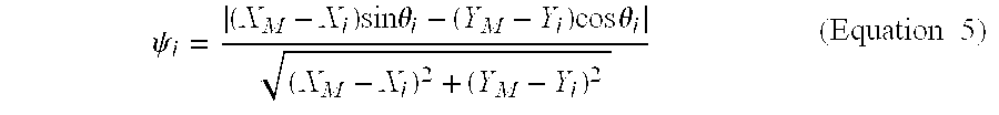
In order to improve the maximum likelihood calculation discussed above, the next step in the process is to calculate the error in the angular measurement at each base station (step 320). The following equation is exemplary of equations useful for calculating the error of angular measurement at the i-th base station. ψ i = ( X M - X i ) sin θ i - ( Y M - Y i ) cos θ i ( X M - X i ) 2 + ( Y M - Y i ) 2 (Equation  5)
Figure US06456956-20020924-M00004
A list including the error of angle measurement for each bases station is then created. The list of values ψi are then sorted in accordance with their absolute value |ψi|. The root means square of the list of ψi values, RMS (ψ) is then calculated.
In the next step, those error of angular measurements whose absolute value exceeds a threshold valued are selected (step 330). The selected value should be chosen to be much greater than RMS (ψ). An example of a threshold value is 1.5 times RMS (ψ).
Next, a new maximum likelihood position is calculated using equations 3 and 4 and the values of those base stations whose error of angular measurement values were not selected in the previous step (step 340). An improved position estimation is thereby calculated.
In an alternate embodiment, the above procedure of culling out those base stations whose error values exceed a certain threshold value (steps 330 and 340) may be repeated by lowering the threshold to select more base stations. The removal of base stations will automatically stop when there are no more base stations whose angular measurement error is much larger than normal, i.e., the process has a value beyond which it will not lower the threshold value, for example 1.2 times RMS (ψ). Once the threshold reaches that value, no more iterations are performed.
An example of the operation of the above described process will now be presented. We will look at situations that involve a varying number of N base stations. In the case of N base station involvement, they are assumed to be located along a circle of a radius of 5 km. The angular separation of the close-by base stations is 2π/N for N>2. In the case of N=2, the angular separation of the two base stations is chosen to be π/2, the configuration that works most efficiently for a two-station system. The transmitter is assumed to be located at the center of the circle.
The LOS signals are assumed to follow a Gaussian distribution in the angular response, with its mean corresponding to the exact angle from the location of the base station to the mobile. The standard deviation of the Gaussian distribution is chosen to be σ=1°, 5°, 10° respectively. For the NLOS signals, the AOA is assumed to be a value uni-randomly distributed between (−π, π).
Each experiment of the position estimation is considered to be with one configuration of the AOA so generated. From many such experiments, or runs, statistical data may be collected for the accuracy of the position estimation. Consider the distance from the true position to the estimated position to be R, the root mean square of R is our performance criterion of position estimation. It characterizes the typical size of a circle that the mobile phone may lie in.
In FIG. 4 we show the performance of AOA location technique with the number of base stations running from 2 to 8. Three curves are presented for the angular spread 1°, 5°, 10° degrees. With an increasing number of base stations, the accuracy of the position estimation improves consistently, especially when large angular errors are present at the base stations. Although the accuracy in the positioning would eventually saturate with enough base stations, the practice of involving more than 2, the minimum number required, improves the accuracy greatly.
In FIG. 5 we show the accuracy of the location estimation as a function of angular spread of the base station measurement. The dependence of the two quantities is almost linear. This should be the case in the small angle limit, wherein the chord subtended by an angle is proportional to the angle. Another interesting observation of the figure is that the performance of a large-N system is less susceptible to the angular measuring error at the base stations.
In FIG. 6 we show the effect of NLOS in position accuracy and the efficiency of the selective model. The curves with squares or large circles as reference marks include all of the base stations in the calculation. The curves with triangles or small circles as reference marks are results obtained with the proposed selective model. For the curves called NLOS curves, only one out of the N base stations is assumed to have the NLOS signal. The other N−1 ase stations have received normal signals whose angular error has 1° in s.t.d. One can see that even only one NLOS is damaging enough to the accuracy. But with the selective model, one can very efficiently diagnose and reduce the errors raised by the NLOS signal. It works particularly well when base stations are in surplus. Also in FIG. 6 we have superimposed for comparison a results set where all N signals are LOS signals.
One can see that using the selective model designed for mitigating the NLOS signals will not introduce extra error when NLOS is not present. Also in the large N limit, the error due to NLOS can be eliminated almost completely.
It will be apparent to those skilled in the art that various modifications and variations can be made in the calculations of the present invention and in the selection of signals to discard without departing from the scope or spirit of the invention.
Other embodiments of the invention will be apparent to those skilled in the art from consideration of the specification and practice of the invention disclosed herein. It is intended that the specification and examples be considered as exemplary only, with a true scope and spirit of the invention being indicated by the following claims.

Claims (2)

What is claimed is:
1. A method of estimating the position of a transmitter using a direction estimation from each of a plurality of receivers comprising:
a) calculating a first position estimation using each of the direction estimations;
b) calculating an error in the direction estimation for each receiver;
c) selecting those receivers whose measurement error is below a first threshold;
d) calculating a second position estimation using the direction estimations of the selected receivers; and
e) recursively performing steps c) and d) with lower first threshold values until all of the selected receivers have measurement errors below a second threshold.
2. The method of claim 1, wherein the direction estimations are angle-of-arrival direction estimations.
US09/393,050 1999-09-09 1999-09-09 Algorithm for selectively suppressing NLOS signals in location estimation Expired - Lifetime US6456956B1 (en)

Priority Applications (1)

Application Number Priority Date Filing Date Title
US09/393,050 US6456956B1 (en) 1999-09-09 1999-09-09 Algorithm for selectively suppressing NLOS signals in location estimation

Applications Claiming Priority (1)

Application Number Priority Date Filing Date Title
US09/393,050 US6456956B1 (en) 1999-09-09 1999-09-09 Algorithm for selectively suppressing NLOS signals in location estimation

Publications (1)

Publication Number Publication Date
US6456956B1 true US6456956B1 (en) 2002-09-24

Family

ID=23553078

Family Applications (1)

Application Number Title Priority Date Filing Date
US09/393,050 Expired - Lifetime US6456956B1 (en) 1999-09-09 1999-09-09 Algorithm for selectively suppressing NLOS signals in location estimation

Country Status (1)

Country Link
US (1) US6456956B1 (en)

Cited By (32)

* Cited by examiner, † Cited by third party
Publication number Priority date Publication date Assignee Title
US20040127228A1 (en) * 2002-12-30 2004-07-01 You Heung Ryeol Method for correcting NLOS error in wireless positioning system
US8031050B2 (en) 2000-06-07 2011-10-04 Apple Inc. System and method for situational location relevant invocable speed reference
US8060389B2 (en) 2000-06-07 2011-11-15 Apple Inc. System and method for anonymous location based services
US8073565B2 (en) 2000-06-07 2011-12-06 Apple Inc. System and method for alerting a first mobile data processing system nearby a second mobile data processing system
US8108144B2 (en) 2007-06-28 2012-01-31 Apple Inc. Location based tracking
US8175802B2 (en) 2007-06-28 2012-05-08 Apple Inc. Adaptive route guidance based on preferences
US8180379B2 (en) 2007-06-28 2012-05-15 Apple Inc. Synchronizing mobile and vehicle devices
US8204684B2 (en) 2007-06-28 2012-06-19 Apple Inc. Adaptive mobile device navigation
US8260320B2 (en) 2008-11-13 2012-09-04 Apple Inc. Location specific content
US8275352B2 (en) 2007-06-28 2012-09-25 Apple Inc. Location-based emergency information
US8290513B2 (en) 2007-06-28 2012-10-16 Apple Inc. Location-based services
US8311526B2 (en) 2007-06-28 2012-11-13 Apple Inc. Location-based categorical information services
US8332402B2 (en) 2007-06-28 2012-12-11 Apple Inc. Location based media items
US8355862B2 (en) 2008-01-06 2013-01-15 Apple Inc. Graphical user interface for presenting location information
US8359643B2 (en) 2008-09-18 2013-01-22 Apple Inc. Group formation using anonymous broadcast information
US8369867B2 (en) 2008-06-30 2013-02-05 Apple Inc. Location sharing
US8385964B2 (en) 2005-04-04 2013-02-26 Xone, Inc. Methods and apparatuses for geospatial-based sharing of information by multiple devices
US8644843B2 (en) 2008-05-16 2014-02-04 Apple Inc. Location determination
US8660530B2 (en) 2009-05-01 2014-02-25 Apple Inc. Remotely receiving and communicating commands to a mobile device for execution by the mobile device
US8666367B2 (en) 2009-05-01 2014-03-04 Apple Inc. Remotely locating and commanding a mobile device
US8670748B2 (en) 2009-05-01 2014-03-11 Apple Inc. Remotely locating and commanding a mobile device
US8762056B2 (en) 2007-06-28 2014-06-24 Apple Inc. Route reference
US8774825B2 (en) 2007-06-28 2014-07-08 Apple Inc. Integration of map services with user applications in a mobile device
US20140219569A1 (en) * 2013-02-07 2014-08-07 Raytheon Company Image recognition system and method for identifying similarities in different images
WO2014179399A1 (en) * 2013-05-01 2014-11-06 Qualcomm Incorporated Methods and apparatuses for characterizing and affecting mobile device location accuracy and/or uncertainty
US9066199B2 (en) 2007-06-28 2015-06-23 Apple Inc. Location-aware mobile device
US9109904B2 (en) 2007-06-28 2015-08-18 Apple Inc. Integration of map services and user applications in a mobile device
US9250092B2 (en) 2008-05-12 2016-02-02 Apple Inc. Map service with network-based query for search
US20160277899A1 (en) * 2015-03-18 2016-09-22 Sony Corporation Fingerprint matching in massive mimo systems
US9702709B2 (en) 2007-06-28 2017-07-11 Apple Inc. Disfavored route progressions or locations
WO2020074070A1 (en) * 2018-10-09 2020-04-16 Nokia Technologies Oy Positioning system and method
US20210389409A1 (en) * 2018-10-09 2021-12-16 Nokia Solutions And Networks Oy Location estimation

Citations (3)

* Cited by examiner, † Cited by third party
Publication number Priority date Publication date Assignee Title
US6064942A (en) * 1997-05-30 2000-05-16 Rockwell Collins, Inc. Enhanced precision forward observation system and method
US6266014B1 (en) * 1998-10-09 2001-07-24 Cell-Loc Inc. Methods and apparatus to position a mobile receiver using downlink signals part IV
US6278404B1 (en) * 1998-07-08 2001-08-21 The United States Of America As Represented By The United States National Aeronautics And Space Administration Global positioning system satellite selection method

Patent Citations (3)

* Cited by examiner, † Cited by third party
Publication number Priority date Publication date Assignee Title
US6064942A (en) * 1997-05-30 2000-05-16 Rockwell Collins, Inc. Enhanced precision forward observation system and method
US6278404B1 (en) * 1998-07-08 2001-08-21 The United States Of America As Represented By The United States National Aeronautics And Space Administration Global positioning system satellite selection method
US6266014B1 (en) * 1998-10-09 2001-07-24 Cell-Loc Inc. Methods and apparatus to position a mobile receiver using downlink signals part IV

Non-Patent Citations (7)

* Cited by examiner, † Cited by third party
Title
Hamid Krim et al., Two Decades of Array Signal Processing Research, 13 IEEE Signal Processing, 67(1996).
Kevin J. Krizman et al., Wireless Position Location: Fundamentals, Implementation Strategies, and Sources of Error, IEEE 47th Vehicular Technology Conference Proceedings, 919 (1997).
Marilynn P. Wylie et al., The Non-Line of Sight Problem in Mobile Location Estimation, IEEE 5th International Conference on Universal Personal Communication, 827 (1996).
Marko Silventoinen et al., Mobile Station Locating in GSM, IEEE Wireless Communication System Symposium, 53 (1995).
Merriam-Webster, Merriam-Webster's Collegiate Dictionary (10th ed.), pp. 622 and 975 (1993).* *
R. G. Stansfield, Statistical Theory of D.F. Fixing, 94 The Journal of the Institution of Electrical Engineers, 762 (1947).
Ralph O. Schmidt, Multiple Emitter Location and Signal Parameter Estimation, 34 IEEE Transactions on Antennas and Propagation, 276 (1986).

Cited By (100)

* Cited by examiner, † Cited by third party
Publication number Priority date Publication date Assignee Title
US8489669B2 (en) 2000-06-07 2013-07-16 Apple Inc. Mobile data processing system moving interest radius
US8031050B2 (en) 2000-06-07 2011-10-04 Apple Inc. System and method for situational location relevant invocable speed reference
US8060389B2 (en) 2000-06-07 2011-11-15 Apple Inc. System and method for anonymous location based services
US8073565B2 (en) 2000-06-07 2011-12-06 Apple Inc. System and method for alerting a first mobile data processing system nearby a second mobile data processing system
US9317867B2 (en) 2000-06-07 2016-04-19 Apple Inc. System and method for situational location relevant invocable speed reference
US9100793B2 (en) 2000-06-07 2015-08-04 Apple Inc. System and method for alerting a first mobile data processing system nearby a second mobile data processing system
US8984059B2 (en) 2000-06-07 2015-03-17 Apple Inc. Mobile data processing system moving interest radius
US8963686B2 (en) 2000-06-07 2015-02-24 Apple Inc. System and method for situational location relevant invocable speed reference
US8930233B2 (en) 2000-06-07 2015-01-06 Apple Inc. System and method for anonymous location based services
US8538685B2 (en) 2000-06-07 2013-09-17 Apple Inc. System and method for internet connected service providing heterogeneous mobile systems with situational location relevant content
US7065368B2 (en) * 2002-12-30 2006-06-20 Kt Corporation Method for correcting NLOS error in wireless positioning system
US20040127228A1 (en) * 2002-12-30 2004-07-01 You Heung Ryeol Method for correcting NLOS error in wireless positioning system
US9967704B1 (en) 2005-04-04 2018-05-08 X One, Inc. Location sharing group map management
US9854394B1 (en) 2005-04-04 2017-12-26 X One, Inc. Ad hoc location sharing group between first and second cellular wireless devices
US10313826B2 (en) 2005-04-04 2019-06-04 X One, Inc. Location sharing and map support in connection with services request
US10299071B2 (en) 2005-04-04 2019-05-21 X One, Inc. Server-implemented methods and systems for sharing location amongst web-enabled cell phones
US10200811B1 (en) 2005-04-04 2019-02-05 X One, Inc. Map presentation on cellular device showing positions of multiple other wireless device users
US8385964B2 (en) 2005-04-04 2013-02-26 Xone, Inc. Methods and apparatuses for geospatial-based sharing of information by multiple devices
US10341809B2 (en) 2005-04-04 2019-07-02 X One, Inc. Location sharing with facilitated meeting point definition
US10750311B2 (en) 2005-04-04 2020-08-18 X One, Inc. Application-based tracking and mapping function in connection with vehicle-based services provision
US8538458B2 (en) 2005-04-04 2013-09-17 X One, Inc. Location sharing and tracking using mobile phones or other wireless devices
US10165059B2 (en) 2005-04-04 2018-12-25 X One, Inc. Methods, systems and apparatuses for the formation and tracking of location sharing groups
US10149092B1 (en) 2005-04-04 2018-12-04 X One, Inc. Location sharing service between GPS-enabled wireless devices, with shared target location exchange
US10750309B2 (en) 2005-04-04 2020-08-18 X One, Inc. Ad hoc location sharing group establishment for wireless devices with designated meeting point
US9185522B1 (en) 2005-04-04 2015-11-10 X One, Inc. Apparatus and method to transmit content to a cellular wireless device based on proximity to other wireless devices
US9955298B1 (en) 2005-04-04 2018-04-24 X One, Inc. Methods, systems and apparatuses for the formation and tracking of location sharing groups
US9942705B1 (en) 2005-04-04 2018-04-10 X One, Inc. Location sharing group for services provision
US8712441B2 (en) 2005-04-04 2014-04-29 Xone, Inc. Methods and systems for temporarily sharing position data between mobile-device users
US9883360B1 (en) 2005-04-04 2018-01-30 X One, Inc. Rendez vous management using mobile phones or other mobile devices
US8750898B2 (en) 2005-04-04 2014-06-10 X One, Inc. Methods and systems for annotating target locations
US9854402B1 (en) 2005-04-04 2017-12-26 X One, Inc. Formation of wireless device location sharing group
US10341808B2 (en) 2005-04-04 2019-07-02 X One, Inc. Location sharing for commercial and proprietary content applications
US8798647B1 (en) 2005-04-04 2014-08-05 X One, Inc. Tracking proximity of services provider to services consumer
US8798645B2 (en) 2005-04-04 2014-08-05 X One, Inc. Methods and systems for sharing position data and tracing paths between mobile-device users
US8798593B2 (en) 2005-04-04 2014-08-05 X One, Inc. Location sharing and tracking using mobile phones or other wireless devices
US9749790B1 (en) 2005-04-04 2017-08-29 X One, Inc. Rendez vous management using mobile phones or other mobile devices
US8831635B2 (en) 2005-04-04 2014-09-09 X One, Inc. Methods and apparatuses for transmission of an alert to multiple devices
US9736618B1 (en) 2005-04-04 2017-08-15 X One, Inc. Techniques for sharing relative position between mobile devices
US9654921B1 (en) 2005-04-04 2017-05-16 X One, Inc. Techniques for sharing position data between first and second devices
US10750310B2 (en) 2005-04-04 2020-08-18 X One, Inc. Temporary location sharing group with event based termination
US10791414B2 (en) 2005-04-04 2020-09-29 X One, Inc. Location sharing for commercial and proprietary content applications
US10856099B2 (en) 2005-04-04 2020-12-01 X One, Inc. Application-based two-way tracking and mapping function with selected individuals
US9031581B1 (en) 2005-04-04 2015-05-12 X One, Inc. Apparatus and method for obtaining content on a cellular wireless device based on proximity to other wireless devices
US9615204B1 (en) 2005-04-04 2017-04-04 X One, Inc. Techniques for communication within closed groups of mobile devices
US9584960B1 (en) 2005-04-04 2017-02-28 X One, Inc. Rendez vous management using mobile phones or other mobile devices
US9467832B2 (en) 2005-04-04 2016-10-11 X One, Inc. Methods and systems for temporarily sharing position data between mobile-device users
US11356799B2 (en) 2005-04-04 2022-06-07 X One, Inc. Fleet location sharing application in association with services provision
US11778415B2 (en) 2005-04-04 2023-10-03 Xone, Inc. Location sharing application in association with services provision
US9253616B1 (en) 2005-04-04 2016-02-02 X One, Inc. Apparatus and method for obtaining content on a cellular wireless device based on proximity
US9167558B2 (en) 2005-04-04 2015-10-20 X One, Inc. Methods and systems for sharing position data between subscribers involving multiple wireless providers
US10064158B2 (en) 2007-06-28 2018-08-28 Apple Inc. Location aware mobile device
US10952180B2 (en) 2007-06-28 2021-03-16 Apple Inc. Location-aware mobile device
US9131342B2 (en) 2007-06-28 2015-09-08 Apple Inc. Location-based categorical information services
US9310206B2 (en) 2007-06-28 2016-04-12 Apple Inc. Location based tracking
US9109904B2 (en) 2007-06-28 2015-08-18 Apple Inc. Integration of map services and user applications in a mobile device
US9414198B2 (en) 2007-06-28 2016-08-09 Apple Inc. Location-aware mobile device
US8108144B2 (en) 2007-06-28 2012-01-31 Apple Inc. Location based tracking
US11665665B2 (en) 2007-06-28 2023-05-30 Apple Inc. Location-aware mobile device
US9578621B2 (en) 2007-06-28 2017-02-21 Apple Inc. Location aware mobile device
US11419092B2 (en) 2007-06-28 2022-08-16 Apple Inc. Location-aware mobile device
US9066199B2 (en) 2007-06-28 2015-06-23 Apple Inc. Location-aware mobile device
US8924144B2 (en) 2007-06-28 2014-12-30 Apple Inc. Location based tracking
US9702709B2 (en) 2007-06-28 2017-07-11 Apple Inc. Disfavored route progressions or locations
US8175802B2 (en) 2007-06-28 2012-05-08 Apple Inc. Adaptive route guidance based on preferences
US11221221B2 (en) 2007-06-28 2022-01-11 Apple Inc. Location based tracking
US8332402B2 (en) 2007-06-28 2012-12-11 Apple Inc. Location based media items
US8774825B2 (en) 2007-06-28 2014-07-08 Apple Inc. Integration of map services with user applications in a mobile device
US8762056B2 (en) 2007-06-28 2014-06-24 Apple Inc. Route reference
US8180379B2 (en) 2007-06-28 2012-05-15 Apple Inc. Synchronizing mobile and vehicle devices
US8738039B2 (en) 2007-06-28 2014-05-27 Apple Inc. Location-based categorical information services
US9891055B2 (en) 2007-06-28 2018-02-13 Apple Inc. Location based tracking
US8694026B2 (en) 2007-06-28 2014-04-08 Apple Inc. Location based services
US8204684B2 (en) 2007-06-28 2012-06-19 Apple Inc. Adaptive mobile device navigation
US8275352B2 (en) 2007-06-28 2012-09-25 Apple Inc. Location-based emergency information
US8290513B2 (en) 2007-06-28 2012-10-16 Apple Inc. Location-based services
US10508921B2 (en) 2007-06-28 2019-12-17 Apple Inc. Location based tracking
US10412703B2 (en) 2007-06-28 2019-09-10 Apple Inc. Location-aware mobile device
US8548735B2 (en) 2007-06-28 2013-10-01 Apple Inc. Location based tracking
US8311526B2 (en) 2007-06-28 2012-11-13 Apple Inc. Location-based categorical information services
US8355862B2 (en) 2008-01-06 2013-01-15 Apple Inc. Graphical user interface for presenting location information
US9702721B2 (en) 2008-05-12 2017-07-11 Apple Inc. Map service with network-based query for search
US9250092B2 (en) 2008-05-12 2016-02-02 Apple Inc. Map service with network-based query for search
US8644843B2 (en) 2008-05-16 2014-02-04 Apple Inc. Location determination
US8369867B2 (en) 2008-06-30 2013-02-05 Apple Inc. Location sharing
US10368199B2 (en) 2008-06-30 2019-07-30 Apple Inc. Location sharing
US10841739B2 (en) 2008-06-30 2020-11-17 Apple Inc. Location sharing
US8359643B2 (en) 2008-09-18 2013-01-22 Apple Inc. Group formation using anonymous broadcast information
US8260320B2 (en) 2008-11-13 2012-09-04 Apple Inc. Location specific content
US8660530B2 (en) 2009-05-01 2014-02-25 Apple Inc. Remotely receiving and communicating commands to a mobile device for execution by the mobile device
US8666367B2 (en) 2009-05-01 2014-03-04 Apple Inc. Remotely locating and commanding a mobile device
US8670748B2 (en) 2009-05-01 2014-03-11 Apple Inc. Remotely locating and commanding a mobile device
US9979776B2 (en) 2009-05-01 2018-05-22 Apple Inc. Remotely locating and commanding a mobile device
US20140219569A1 (en) * 2013-02-07 2014-08-07 Raytheon Company Image recognition system and method for identifying similarities in different images
US9092697B2 (en) * 2013-02-07 2015-07-28 Raytheon Company Image recognition system and method for identifying similarities in different images
WO2014179399A1 (en) * 2013-05-01 2014-11-06 Qualcomm Incorporated Methods and apparatuses for characterizing and affecting mobile device location accuracy and/or uncertainty
US9078232B2 (en) 2013-05-01 2015-07-07 Qualcomm, Incorporated Methods and apparatuses for characterizing and affecting mobile device location accuracy and/or uncertainty
US9860705B2 (en) * 2015-03-18 2018-01-02 Sony Corporation Fingerprint matching in massive MIMO systems
US20160277899A1 (en) * 2015-03-18 2016-09-22 Sony Corporation Fingerprint matching in massive mimo systems
US20210389409A1 (en) * 2018-10-09 2021-12-16 Nokia Solutions And Networks Oy Location estimation
WO2020074070A1 (en) * 2018-10-09 2020-04-16 Nokia Technologies Oy Positioning system and method

Similar Documents

Publication Publication Date Title
US6456956B1 (en) Algorithm for selectively suppressing NLOS signals in location estimation
Xiong A selective model to suppress NLOS signals in angle-of-arrival (AOA) location estimation
Liu et al. Improving positioning accuracy using GPS pseudorange measurements for cooperative vehicular localization
US7956808B2 (en) Method for position estimation using generalized error distributions
US7057557B2 (en) Apparatus and method for estimating position of mobile communication terminal
EP1312234B1 (en) Systems and methods for determining signal coverage
Cong et al. Non-line-of-sight error mitigation in TDOA mobile location
US6799047B1 (en) Locating and tracking a user in a wireless network through environmentally profiled data
EP1445970B1 (en) A method and system for locating a mobile radio receiver in a radio system with multiple tranmitters
US9599696B2 (en) Procedure to increase position location availability
EP1197114B1 (en) Selection of location measurement units for determining the position of a mobile communication station
CN100420958C (en) Method and apparatus for providing accurate position estimates in instances of severe dilution of precision
EP0982964B1 (en) Pattern recognition-based geolocation
USRE45260E1 (en) Using a derived table of signal strength data to locate and track a user in a wireless network
US20100295734A1 (en) Method and apparatus of using soft information for enhancing accuracy of position estimation for a wireless communication system
US8712428B2 (en) Location estimation of wireless terminals through pattern matching of deduced signal strengths
CN103501538B (en) Based on the indoor orientation method of multipath energy fingerprint
US20100323723A1 (en) Base Station Mapping with Angle-of-Arrival and Timing Advance Measurements
US20030176196A1 (en) Method and apparatus for geolocating a wireless communications device
EP2551696A2 (en) System and method for direction finding and geolocation of emitters based on line-of-bearing intersections
US20110316748A1 (en) Device and Method for Estimating an Orientation of a Mobile Terminal Device
US20040132464A1 (en) Location system
US20100137005A1 (en) Method for positioning portable communication device
CN103618997A (en) Indoor positioning method and device based on signal intensity probability
KR100863917B1 (en) Estimating a position of a wireless mobile device with respect to one or more base station

Legal Events

Date Code Title Description
AS Assignment

Owner name: GTE LABORATORIES INCORPORATED, MASSACHUSETTS

Free format text: ASSIGNMENT OF ASSIGNORS INTEREST;ASSIGNOR:XIONG, LI;REEL/FRAME:010241/0815

Effective date: 19990908

AS Assignment

Owner name: VERIZON LABORATORIES INC., MASSACHUSETTS

Free format text: CHANGE OF NAME;ASSIGNOR:GTE LABORATORIES INCORPORATED;REEL/FRAME:012257/0147

Effective date: 20000630

STCF Information on status: patent grant

Free format text: PATENTED CASE

FPAY Fee payment

Year of fee payment: 4

FPAY Fee payment

Year of fee payment: 8

FPAY Fee payment

Year of fee payment: 12